EP3110532B1 - Systeme zur verwendung des wassergehalts in einer flüssigkeit aus einem nierenersatztherapieverfahren - Google Patents
Systeme zur verwendung des wassergehalts in einer flüssigkeit aus einem nierenersatztherapieverfahren Download PDFInfo
- Publication number
- EP3110532B1 EP3110532B1 EP15708755.2A EP15708755A EP3110532B1 EP 3110532 B1 EP3110532 B1 EP 3110532B1 EP 15708755 A EP15708755 A EP 15708755A EP 3110532 B1 EP3110532 B1 EP 3110532B1
- Authority
- EP
- European Patent Office
- Prior art keywords
- water
- membrane
- concentrate
- hemofiltration
- fluid
- Prior art date
- Legal status (The legal status is an assumption and is not a legal conclusion. Google has not performed a legal analysis and makes no representation as to the accuracy of the status listed.)
- Active
Links
Images



Classifications
-
- A—HUMAN NECESSITIES
- A61—MEDICAL OR VETERINARY SCIENCE; HYGIENE
- A61M—DEVICES FOR INTRODUCING MEDIA INTO, OR ONTO, THE BODY; DEVICES FOR TRANSDUCING BODY MEDIA OR FOR TAKING MEDIA FROM THE BODY; DEVICES FOR PRODUCING OR ENDING SLEEP OR STUPOR
- A61M1/00—Suction or pumping devices for medical purposes; Devices for carrying-off, for treatment of, or for carrying-over, body-liquids; Drainage systems
- A61M1/14—Dialysis systems; Artificial kidneys; Blood oxygenators ; Reciprocating systems for treatment of body fluids, e.g. single needle systems for hemofiltration or pheresis
- A61M1/16—Dialysis systems; Artificial kidneys; Blood oxygenators ; Reciprocating systems for treatment of body fluids, e.g. single needle systems for hemofiltration or pheresis with membranes
- A61M1/1694—Dialysis systems; Artificial kidneys; Blood oxygenators ; Reciprocating systems for treatment of body fluids, e.g. single needle systems for hemofiltration or pheresis with membranes with recirculating dialysing liquid
- A61M1/1696—Dialysis systems; Artificial kidneys; Blood oxygenators ; Reciprocating systems for treatment of body fluids, e.g. single needle systems for hemofiltration or pheresis with membranes with recirculating dialysing liquid with dialysate regeneration
-
- A—HUMAN NECESSITIES
- A61—MEDICAL OR VETERINARY SCIENCE; HYGIENE
- A61M—DEVICES FOR INTRODUCING MEDIA INTO, OR ONTO, THE BODY; DEVICES FOR TRANSDUCING BODY MEDIA OR FOR TAKING MEDIA FROM THE BODY; DEVICES FOR PRODUCING OR ENDING SLEEP OR STUPOR
- A61M1/00—Suction or pumping devices for medical purposes; Devices for carrying-off, for treatment of, or for carrying-over, body-liquids; Drainage systems
- A61M1/34—Filtering material out of the blood by passing it through a membrane, i.e. hemofiltration or diafiltration
- A61M1/3472—Filtering material out of the blood by passing it through a membrane, i.e. hemofiltration or diafiltration with treatment of the filtrate
- A61M1/3479—Filtering material out of the blood by passing it through a membrane, i.e. hemofiltration or diafiltration with treatment of the filtrate by dialysing the filtrate
-
- A—HUMAN NECESSITIES
- A61—MEDICAL OR VETERINARY SCIENCE; HYGIENE
- A61M—DEVICES FOR INTRODUCING MEDIA INTO, OR ONTO, THE BODY; DEVICES FOR TRANSDUCING BODY MEDIA OR FOR TAKING MEDIA FROM THE BODY; DEVICES FOR PRODUCING OR ENDING SLEEP OR STUPOR
- A61M1/00—Suction or pumping devices for medical purposes; Devices for carrying-off, for treatment of, or for carrying-over, body-liquids; Drainage systems
- A61M1/34—Filtering material out of the blood by passing it through a membrane, i.e. hemofiltration or diafiltration
- A61M1/342—Adding solutions to the blood, e.g. substitution solutions
- A61M1/3424—Substitution fluid path
- A61M1/3431—Substitution fluid path upstream of the filter
-
- A—HUMAN NECESSITIES
- A61—MEDICAL OR VETERINARY SCIENCE; HYGIENE
- A61M—DEVICES FOR INTRODUCING MEDIA INTO, OR ONTO, THE BODY; DEVICES FOR TRANSDUCING BODY MEDIA OR FOR TAKING MEDIA FROM THE BODY; DEVICES FOR PRODUCING OR ENDING SLEEP OR STUPOR
- A61M1/00—Suction or pumping devices for medical purposes; Devices for carrying-off, for treatment of, or for carrying-over, body-liquids; Drainage systems
- A61M1/34—Filtering material out of the blood by passing it through a membrane, i.e. hemofiltration or diafiltration
- A61M1/342—Adding solutions to the blood, e.g. substitution solutions
- A61M1/3424—Substitution fluid path
- A61M1/3431—Substitution fluid path upstream of the filter
- A61M1/3434—Substitution fluid path upstream of the filter with pre-dilution and post-dilution
-
- A—HUMAN NECESSITIES
- A61—MEDICAL OR VETERINARY SCIENCE; HYGIENE
- A61M—DEVICES FOR INTRODUCING MEDIA INTO, OR ONTO, THE BODY; DEVICES FOR TRANSDUCING BODY MEDIA OR FOR TAKING MEDIA FROM THE BODY; DEVICES FOR PRODUCING OR ENDING SLEEP OR STUPOR
- A61M1/00—Suction or pumping devices for medical purposes; Devices for carrying-off, for treatment of, or for carrying-over, body-liquids; Drainage systems
- A61M1/34—Filtering material out of the blood by passing it through a membrane, i.e. hemofiltration or diafiltration
- A61M1/342—Adding solutions to the blood, e.g. substitution solutions
- A61M1/3424—Substitution fluid path
- A61M1/3437—Substitution fluid path downstream of the filter, e.g. post-dilution with filtrate
-
- A—HUMAN NECESSITIES
- A61—MEDICAL OR VETERINARY SCIENCE; HYGIENE
- A61M—DEVICES FOR INTRODUCING MEDIA INTO, OR ONTO, THE BODY; DEVICES FOR TRANSDUCING BODY MEDIA OR FOR TAKING MEDIA FROM THE BODY; DEVICES FOR PRODUCING OR ENDING SLEEP OR STUPOR
- A61M1/00—Suction or pumping devices for medical purposes; Devices for carrying-off, for treatment of, or for carrying-over, body-liquids; Drainage systems
- A61M1/34—Filtering material out of the blood by passing it through a membrane, i.e. hemofiltration or diafiltration
- A61M1/342—Adding solutions to the blood, e.g. substitution solutions
- A61M1/3455—Substitution fluids
- A61M1/3458—Substitution fluids having electrolytes not present in the dialysate
-
- A—HUMAN NECESSITIES
- A61—MEDICAL OR VETERINARY SCIENCE; HYGIENE
- A61M—DEVICES FOR INTRODUCING MEDIA INTO, OR ONTO, THE BODY; DEVICES FOR TRANSDUCING BODY MEDIA OR FOR TAKING MEDIA FROM THE BODY; DEVICES FOR PRODUCING OR ENDING SLEEP OR STUPOR
- A61M1/00—Suction or pumping devices for medical purposes; Devices for carrying-off, for treatment of, or for carrying-over, body-liquids; Drainage systems
- A61M1/34—Filtering material out of the blood by passing it through a membrane, i.e. hemofiltration or diafiltration
- A61M1/342—Adding solutions to the blood, e.g. substitution solutions
- A61M1/3455—Substitution fluids
- A61M1/3468—Substitution fluids using treated filtrate as substitution fluid
-
- A—HUMAN NECESSITIES
- A61—MEDICAL OR VETERINARY SCIENCE; HYGIENE
- A61M—DEVICES FOR INTRODUCING MEDIA INTO, OR ONTO, THE BODY; DEVICES FOR TRANSDUCING BODY MEDIA OR FOR TAKING MEDIA FROM THE BODY; DEVICES FOR PRODUCING OR ENDING SLEEP OR STUPOR
- A61M1/00—Suction or pumping devices for medical purposes; Devices for carrying-off, for treatment of, or for carrying-over, body-liquids; Drainage systems
- A61M1/34—Filtering material out of the blood by passing it through a membrane, i.e. hemofiltration or diafiltration
- A61M1/3472—Filtering material out of the blood by passing it through a membrane, i.e. hemofiltration or diafiltration with treatment of the filtrate
-
- A—HUMAN NECESSITIES
- A61—MEDICAL OR VETERINARY SCIENCE; HYGIENE
- A61M—DEVICES FOR INTRODUCING MEDIA INTO, OR ONTO, THE BODY; DEVICES FOR TRANSDUCING BODY MEDIA OR FOR TAKING MEDIA FROM THE BODY; DEVICES FOR PRODUCING OR ENDING SLEEP OR STUPOR
- A61M1/00—Suction or pumping devices for medical purposes; Devices for carrying-off, for treatment of, or for carrying-over, body-liquids; Drainage systems
- A61M1/34—Filtering material out of the blood by passing it through a membrane, i.e. hemofiltration or diafiltration
- A61M1/3472—Filtering material out of the blood by passing it through a membrane, i.e. hemofiltration or diafiltration with treatment of the filtrate
- A61M1/3482—Filtering material out of the blood by passing it through a membrane, i.e. hemofiltration or diafiltration with treatment of the filtrate by filtrating the filtrate using another cross-flow filter, e.g. a membrane filter
-
- B—PERFORMING OPERATIONS; TRANSPORTING
- B01—PHYSICAL OR CHEMICAL PROCESSES OR APPARATUS IN GENERAL
- B01D—SEPARATION
- B01D61/00—Processes of separation using semi-permeable membranes, e.g. dialysis, osmosis or ultrafiltration; Apparatus, accessories or auxiliary operations specially adapted therefor
- B01D61/002—Forward osmosis or direct osmosis
- B01D61/0022—Apparatus therefor
-
- B—PERFORMING OPERATIONS; TRANSPORTING
- B01—PHYSICAL OR CHEMICAL PROCESSES OR APPARATUS IN GENERAL
- B01D—SEPARATION
- B01D61/00—Processes of separation using semi-permeable membranes, e.g. dialysis, osmosis or ultrafiltration; Apparatus, accessories or auxiliary operations specially adapted therefor
- B01D61/14—Ultrafiltration; Microfiltration
- B01D61/145—Ultrafiltration
-
- B—PERFORMING OPERATIONS; TRANSPORTING
- B01—PHYSICAL OR CHEMICAL PROCESSES OR APPARATUS IN GENERAL
- B01D—SEPARATION
- B01D69/00—Semi-permeable membranes for separation processes or apparatus characterised by their form, structure or properties; Manufacturing processes specially adapted therefor
- B01D69/12—Composite membranes; Ultra-thin membranes
- B01D69/1214—Chemically bonded layers, e.g. cross-linking
-
- B—PERFORMING OPERATIONS; TRANSPORTING
- B01—PHYSICAL OR CHEMICAL PROCESSES OR APPARATUS IN GENERAL
- B01D—SEPARATION
- B01D69/00—Semi-permeable membranes for separation processes or apparatus characterised by their form, structure or properties; Manufacturing processes specially adapted therefor
- B01D69/14—Dynamic membranes
- B01D69/141—Heterogeneous membranes, e.g. containing dispersed material; Mixed matrix membranes
- B01D69/142—Heterogeneous membranes, e.g. containing dispersed material; Mixed matrix membranes with "carriers"
- B01D69/144—Heterogeneous membranes, e.g. containing dispersed material; Mixed matrix membranes with "carriers" containing embedded or bound biomolecules
Definitions
- the present invention relates to a system for recycling at least a part of water lost during various renal replacement therapy processes, e.g. in the preparation of a fresh dialysate solution or fresh replacement or reconstitution fluid for hemofiltration and kidney disease dialysis by utilizing water from the spent or waste fluids.
- the system of the invention is useful in a continuous renal replacement therapy, such as hemofiltration, as well as in hemodialysis and in peritoneal dialysis for reuse of water from filtrates and spent fluids.
- the system of the invention is useful in the development of a renal assist device or artificial kidney. Methods and uses of the systems and membranes of the present invention are also disclosed.
- Hemofiltration and dialysis are different types of treatment for patients that suffer from kidney failure.
- the patient's blood is utilized to remove waste, toxins and excess water from the patient.
- the patient is connected to a hemodialysis machine and the patient's blood is pumped through the machine.
- Catheters are inserted into the patient's veins and arteries to connect the blood flow to and from the hemodialysis machine.
- the dialyzer removes the waste, toxins and excess water from the patient's blood and returns the blood to infuse back into the patient.
- toxins and excess water are also removed from the patient's blood.
- the patient is connected to the hemofiltration system - intermittently or continuously - and blood from the patient passes through a system with a hemofilter.
- no dialysate is used in hemofiltration and the movement of solvent and solutes across the membrane is governed by convection rather than diffusion, mimicking the microfiltration process of a normal kidney.
- continuous hemofiltration between 0 and 2000 mL of water may be lost per hour. This means that a considerable volume of water may have to be replaced depending on the individual patient's need.
- the demand for replacement fluid can be as much as 3 to 4 liters per hour.
- dialysate for example about 120 liters
- the spent dialysate in then discarded.
- a healthy individual would intake around 2 liters per day or 14 liters per week.
- large amounts of purified water are used for peritoneal dialysis, such as 12 liters per day during continuous ambulatory peritoneal dialysis, CAPD, and up to 25 liters per night during automatical fluid replacement while the patient is sleeping (automated peritoneal dialysis, APD).
- Dialysis is a life saving treatment for end stage kidney disease patients. However, it requires large scale comsumption of highly purified water for the preparation of replacement fluids as well as dialysate solutions.
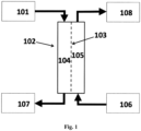
- the present invention provides a system or apparatus for utilizing the water content in spent fluid (101), such as filtrate derived from a patient's blood or plasma during a renal replacement therapy process, said system or apparatus providing a flux of water from said spent fluid by forward osmosis and defined in the claims.
- spent fluid such as filtrate derived from a patient's blood or plasma during a renal replacement therapy process
- the present invention achieves this with a system for recycling at least a part of the water content in waste fluid (507) from a hemofiltration process resulting in a flux of water from said waste fluid into a supply of electrolyte replacement concentrate (509) or into a stream of concentrated blood resulting from said hemofiltration (505), said system comprising a forward osmosis (FO) unit (102, 506) comprising a forward osmosis membrane (103) comprising nanoporous water channels, said membrane having a feed side (104) and a draw side (105) wherein the feed side is in fluid communication with said waste fluid (507) being the filtrate from a patient undergoing said hemofiltration, and wherein the draw side is in fluid communication with a supply of said electrolyte concentrate (509) or wherein the draw side is in fluid communication with a stream of concentrated blood resulting from said hemofiltration (505).
- a forward osmosis (FO) unit comprising a forward osmosis membrane (103) comprising nanoporous water channels, said membrane having
- said system comprises a forward osmosis (FO) unit (102) comprising a forward osmosis membrane (103) having a feed side (104) and a draw side (105), wherein the feed side is in fluid communication with filtrate waste fluid or spent fluid from a patient undergoing a renal replacement therapy; and wherein the draw side is in fluid communication with a supply of electrolyte replacement concentrate, or a flow of concentrated blood having undergone hemofiltration (106), and where said forward osmosis membrane has an active layer which comprises nanoporous water channels which are aquaporin water channels.
- the FO unit may conveniently be in the form of a filter cartridge comprising a hollow fiber module.
- Such a module has the advantage of being compact and has a well-known form factor for use in hemofiltration apparatus.
- the module can be easy to replace after use in single use applications in continuos renal replacement therapies.
- the use of the system of the present invention is provided for recycling at least a part of the water content in waste fluid from a hemofiltration process resulting in a flux of water from said waste fluid into a supply of electrolyte replacement concentrate or into a stream of concentrated blood resulting from said hemofiltration.
- a forward osmosis membrane comprising nanoporous water channels for use in a method of treating a patient undergoing a hemofiltration in the course of renal replacement therapy, wherein the membrane is part of a forward osmosis (FO) unit and has a feed side and a draw side, the feed side being in fluid communication with a waste fluid which is a filtrate from the patient and the draw side being in fluid communication with a supply of said electrolyte concentrate or a stream of concentrated blood resulting from the hemofiltration, so that a part of the water content in the waste fluid from the hemofiltration is recycled, resulting in a flux of water from the waste fluid into a supply of electrolyte replacement concentrate or into a stream of concentrated blood resulting from said hemofiltration.
- the membranes with nanoporous water channels are the component of the system that is consumed and changed between the treatment of different patients or temporally separated treatments of the same patient.
- a method of using the systems and apparatus described herein for recycling at least a part of the water content in waste fluid from a hemofiltration process in provided.
- the system of the invention for utilizing the pure water content in spent fluids, such as filtrates from hemofiltration therapy, may further provide means for water extraction from filtrates and spent dialysate fluids using a draw solution, such as a stream of concentrated blood and/or fresh replacement fluid or dialysate concentrate for forward osmosis water transport across a semipermeable membrane ideally only allowing H 2 O transportation through nanopores, e.g. such as the water channels of aquaporin proteins.
- the semipermeable forward osmosis membrane useful in the system of the invention would preferably have high salt rejection and high water flux, preferably combined with a low molecular weight cut-off, MWCO.
- TFC thin film composite
- PSf polysulfone
- electrospun support TFC membranes on hydrophilic support and hollow fiber membranes
- Advantages of the system of the present invention may include: reduced energy consumption for reverse osmosis (RO) and ultrafiltration (UF) water purification and reduced water consumption in renal replacement therapy through reuse of water from hemofiltration filtrate and/or spent dialysate fluids; as well as reduction of risk of body exposure to external toxins such as organic water pollutants and endotoxins.
- RO reverse osmosis
- UF ultrafiltration
- the use of the highly selective aquaporin membranes described herein may significantly reduce or eliminate reverse flux of low molecular weight metabolites and the like from the waste fluids during (osmotic) filtration processes, thus enabling the use of said aquaporin membranes in renal assist devices and artificial kidney as well as for the re-use of pure water from said spent or waste fluids.
- the amount and rate of transfer of water may be enhanced and/or controlled.
- a plurality of membranes and/or FO units may be used and may operate in a parallel or serial flow configuration.
- the system may comprise recirculation of the draw and feed solutions within an FO unit in order to optimise water extraction.
- the system of the present invention relates to a system or apparatus useful where said renal replacement therapy process is hemofiltration, the spent fluid is the filtrate (filtered plasma from a patient) from the hemofiltration (507), and the draw side of the FO unit is in fluid communication with a supply of electrolyte replacement concentrate (509), cf. Fig. 5A ; or where the draw side of the FO unit is in fluid communication with a flow of blood having undergone hemofiltration (505) and has lost some of its water content through the hemofiltration, cf. Fig. 5B .
- the FO unit enables reabsorption of water lost from the blood during hemofiltration to either electrolyte replacement concentrate ( Fig. 5A ) or to the concentrated blood ( Fig. 5B ).
- the forward osmosis membrane comprises nanoporous water channels and thereby reducing or eliminating reabsorption of all or most other solutes from the spent fluid.
- the FO unit of the system comprises a membrane comprising aquaporin water channels, which, due to their higly selective nature, only pass pure water molecules.
- the FO unit comprising the FO membrane having nanopores which are aquaporin water channels may be provided in the form of a filter cartridge which can be used as an add on in an apparatus as disclosed in the published patent application US 2010/0121246 A1 relating to a modular hemofiltration apparatus with interactive operator instructions and control system.
- Figs. 5 and 6 therein schematically show components of the apparatus when configured for various therapies. In Fig. 5 the apparatus is set up for carrying out CVVHDF; In Fig. 6 the apparatus may be set up for carrying out CVVHDF
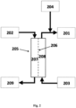
- the renal replacement therapy process is dialysis; the spent fluid is the spent dialysate: and the draw side of the FO unit is in fluid communication with a supply of dialysis concentrate; and a system for preparing a fresh dialysate (201) by utilizing water of the spent dialysate (202), said system comprising i) a supply of dialysis concentrate (203); ii) a supply of purified water (204); and iii) a forward osmosis (FO) unit (205) comprising a forward osmosis membrane (206) having a feed side (207) and a draw side (208), wherein the feed side is in fluid communication with spent dialysate from a patient undergoing dialysis; and wherein the draw side is in fluid communication with the supply of dialysis concentrate.
- system of the invention may be useful in at least partly recycling the purified water used in preparing dialysates for peritoneal dialysis.
- Said membrane comprises
- the amphiphilic matrix forming compounds are selected from an amphiphilic lipid, a hydrophobin, a diblock copolymer, a triblock copolymer or mixtures thereof, and said aquaporin water channel is selected from aquaporins of procaryotic origin, e.g. AqpZ; mammalian aquaporins, e.g. Aqp1 and Aqp2; plant aquaporins including Plasma intrinsic proteins (PIP), Tonoplast intrinsic proteins (TIP), Nodulin intrinsic proteins (NIP), and Small intrinsic proteins (SIP) e.g.
- PIP Plasma intrinsic proteins
- TIP Tonoplast intrinsic proteins
- NIP Nodulin intrinsic proteins
- SIP Small intrinsic proteins
- the system comprises more than one, such as two or three forward osmosis units. This configuration is useful where more than one dialysate concentrate is needed to prepare the final fresh dialysate solution.
- the present invention provides a method for preparing a fresh dialysate solution for dialysis by reusing part of a spent dialysate comprising extracting pure water by use of forward osmosis from the spent dialysate from a patient undergoing hemodialysis.
- this may involve use of the spent dialysate as the feed solution in the forward osmosis process; and a dialysate concentrate constitutes the draw solution in the forward osmosis process.
- highly purified water such as through one or more ultrafiltration steps, as well as sterilization filtration steps, for the preparation of the fresh dialysate would be greatly reduced using this method, thus saving energy, devices, and space among other advantages.
- this method in which the forward osmosis process is used for extracting pure water, may involve the use of a pressure assisted forward osmosis process, e.g. to increase water flux or filtration speed.
- a pressure assisted forward osmosis process e.g. to increase water flux or filtration speed.
- This could be achieved by further including means for pressurizing said feed streams in the system of the invention, e.g. to enable the application of a slight pressure, such as by pumping or using gravity and the like, on the feed side of the aquaporin containing membrane (using the concept of assisted forward osmosis).
- the present invention also relates to a dialysis machine comprising the system for preparing a fresh dialysate solution as described above, and a renal assist device (506) as shown in Fig. 5C and 5D .
- Hemofiltration machines, Hemodialysis machines, dialyzers and replacement fluids, concentrates and solutions for hemofiltration, hemodiafiltration and dialysis are manufactured and sold by a number of companies including Omniflo (subsidiary of Transvivo Inc. Napa, CA, USA), Fresenius Medical Care (fmc-ag.com), Gambro (gambro.com) (now part of Baxter), Nipro (nipro.com), nxStage (nxstage.com) and Bellco (bellco.net).
- Omniflo subsidiary of Transvivo Inc. Napa, CA, USA
- Fresenius Medical Care fmc-ag.com
- Gambro Gambro.com
- Nipro nipro.com
- nxStage nxstage.com
- Bellco bellco.net
- the dialyzer functions partly as an artificial kidney.
- the dialyzer is typical in the form of a hollow fibre module with a bundle of hollow fibres (such as up to 20,000 fibres).
- the lumen of the hollow fibres form the "blood compartment" of the dialyzer and the space surrounding the fibres form the "dialysate compartment”.
- peritoneal dialysis In peritoneal dialysis, the peritoneum in connection with the infused dialysate functions partly as an artificial kidney and the patient's peritoneal membrane functions as a semipermeable membrane across which fluids and dissolved substances are exchanged from the blood.
- Fresh hyperosmotic dialysate solution is introduced through a permanent tube into the abdominal cavity and spent dialysate is flushed out either every night while the patient sleeps (automatic peritoneal dialysis) or via regular exchanges throughout the day (continuous ambulatory peritoneal dialysis).
- composition of a hemofiltration filtrate or ultrafiltrate or a spent dialysate solution varies from patient to patient and from time to time. Metabolic changes appear in patients suffering from kidney failure resulting in elevated urea levels in the patient's blood plasma along with elevated levels of toxic metabolites such as indoles, phenoles, hormones, oxalate and protein degradation products, cf. Table 1 below.
- hemofiltration is a renal replacement therapy used in intensive care, such as for acute renal failure. It is a slow continuous therapy in which sessions usually last between 12 to 24 hours and are usually performed daily.
- a patient's blood is passed via a machine to a semipermeable membrane, typically an ultrafiltration membrane, for removal of waste products and excess water.
- a semipermeable membrane typically an ultrafiltration membrane
- examples of hemofiltration therapies as used herein include CVVH (continuous veno-venous hemofiltration) and CAVH (continuous arteriovenous hemofiltration), SCUF (slow continuous ultrafiltration), CVVHFD (continuous high flux dialysis), HVHF (high volume hemofiltration), cf. also Ronco, C. (2006) Critical Care 10:123 (doi:10.1186/cc4843).
- Hemofiltration is sometimes used in combination with hemodialysis, when it is termed "hemodiafiltration", as used in the CVVHDF therapy of continuous veno-venous hemodiafiltration.
- Blood is pumped through the blood compartment of a high flux dialyzer, and a high rate of ultrafiltration is used, so there is a high rate of movement of water and solutes from blood to dialysate that must be replaced by substitution fluid that is infused directly into the blood line.
- dialysis solution also runs through the dialysate compartment of the dialyzer. The combination is theoretically useful because it results in good removal of both large and small molecular weight solutes.
- Spent fluid or "waste fluid” as used herein include filtrate fluid from hemofiltration and spent dialysate from hemodialysis, and spent fluid (dwell) from peritoneal dialysis.
- the spent fluid is typically diluted during the various renal replacement therapies with water stemming from the blood, plasma, tissue and cells of the patient undergoing said therapy.
- Spent fluid represents an aqueous drainage fluid containing metabolic waste which is discarded continuously during hemofiltration, hemodiafiltration, and hemodialysis, or which is discarded as a batch following a peritoneal dialysis session.
- FO unit refers to a closed housing comprising a semipermeable membrane separating two compartments or regions for i) a preferably aqueous feed solution having relatively low osmolarity or osmotic pressure, and ii) a preferably aqueous draw solution having an osmolarity or osmotic pressure which is higher than that of the feed solution.
- the FO unit has separate inlets and outlets for said feed and draw solutions.
- the FO unit may be of the flat sheet type or hollow fiber type. When the FO unit is of the hollow fiber type the two compartments or regions are variously designated as lumen and shellside space (or extracapillary space), or as lumen side (or tubeside) and shell side.
- AFO assisted forward osmosis
- PAFO pressure assisted forward osmosis
- amphiphilic matrix forming compounds as used herein comprises lipids such as phospholipids; block copolymers having both hydrophilic (A, C) and hydrophobic (B) blocks such as A-B, A-B-A and A-B-C types, and hydrophobins (both class I and class II) that are useful in the preparation of membranes, such as bilayer membranes, and the like.
- the amphiphilic matric forming compounds preferably form bilayer-like planar or vesicular membranes of the lipid membrane type or the block copolymer A-B: :B-A, A-B-A and A-B-C types for incorporation of transmembrane proteins.
- Some amphiphilic matrix forming compounds may be included in smaller amounts the membranes, e.g. detergents such as poloxamers and hydrophobins.
- Purified water Water purity for dialysis is of critical importance for patient health.
- the water used according to the present invention for supplementing the utilized water of the uses dialysate must be of the high purity normally used in preparation of dialysate solutions.
- concentrate formulations for preparing dialysate solutions for hemodialysis or peritoneal dialysis are well known in the art. These formulations vary not only with respect to specific constituents but also with respect to the concentration of these constituents. Generally, concentrate formulations include sodium chloride as the major constituent and potassium chloride, calcium chloride and magnesium chloride as minor substituents. Also dextrose (glucose) may be included.
- Sodium acetate and/or sodium bicarbonate are also included as a buffer source to correct for metabolic acidosis.
- acetate buffer all of the constituents can be combined into a single concentrate.
- bicarbonate buffer two concentrates are necessary to prevent the precipitation of calcium and magnesium as carbonate salts.
- dialysate concentrate systems are (in brackets are mentioned the dilution ratios as volume of acid concentrate to volume of base concentrate to volume of water) the Renasol ® bicarbonate hemodialysis concentrate series (1:1.83:34) and the Centrisol ® hemodialysis concentrate series (1:1.72:42.28) from Medivators (www-medivators.com) (formerly Minntech), the NaturaLyte ® Liquid Acid Concentrates series (1:1.72:42.28) and the Citrasate ® Citric Acid Concentrate series (1:1.72:42.28) from Fresenius Medical Care, the RenalPure ® Liquid Acid Concentrate/ SteriLyte ® series (1:1.83:34, 1:1.72:42.28 and 1:1.225:32.775) from Rockwell Medical (www-rockwellmed.com) and the BiCart Select ® Citrate series (1:ca 2:197) from Gambro (www.gambro.com).
- substitution solutions for hemofiltration and concentrate formulations for preparing substitution solution for hemofiltration are well known in the art. Besides the contribution to the removal of uraemic toxins and the correction of the patient's fluid status, hemofiltration solutions also correct the acid-base-balance of the patient. As renal failure leads to an exhaustion of the buffer systems and, consequently, to the development of metabolic acidosis, the net administration of buffer base is required. Specific examples are the Normocarb HF TM 25 and 35 electrolyte concentrates from Dialysis Solutions Inc. (www.normocarb.com).
- Membrane material comprising aquaporin water channels.
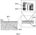
- the membrane material (605) comprises an active layer (601) comprising aquaporin water channels, such as protein tetramers in immobilized form.
- the membrane material (605) further comprises a support layer (602).
- the active layer comprising immobilized aquaporin water channels is a cross linked aromatic amide thin film, wherein aquaporin containing vesicles are incorporated.
- aquaporin containing vesicles are incorporated.
- a section of a vesicle having an aquaporin tetramer incorporated in a lipid bilayer is shown.
- the aquaporin containing vesicles are formed by self assembly of amphiphilic lipids or block copolymers or a mixture thereof in the presence of an aquaporin protein suspension.
- the active layer comprising immobilized aquaporin water channels comprises a thin film composite (TFC) layer that serves to immobilise the aquaporin water channels.
- TFC thin film composite
- the active layer comprising immobilized aquaporin water channels is a cross linked aromatic amide thin film, wherein aquaporin containing vesicles are incorporated.
- the support layer is a polysulfone or polyether sulfone support membrane.
- Aquaporin water channel refers to selective water channel proteins, including AqpZ and SoPIP2;1 prepared according to the methods described by Maria Karlsson et al. (FEBS Letters 537 (2003) 68-72 ) or as described in Jensen et al. US 2012/0080377 A1 .
- the "active layer comprising immobilized aquaporin water channels” is a layer wherein the aquaporin water channels are immobilized, such as or more or less embedded or partly embedded in or even supported in or on said active layer.
- Said active layer is preferably created in close contact with a support layer, such as a typical polysulfone or polyether sulfone support membrane.
- a separation layer in the form of a thin film layer as known in the art onto the surface of a support membrane results in changes to the water transport mechanism.
- another type of water transport takes place through the thin film layer as is known from this type of reverse osmosis membranes, where membrane permeability is limited.
- the nonporous nature of the thin film separating layer results in transport of water requiring "jump diffusion” as described in Kotelyanskii et al. 1998.
- thin film modification of water membranes have mainly found use in reverse osmosis, where a hydrostatic pressure is required to force the water through the membrane, and the obtained advantage lies in the improved separation of unwanted solutes in the water to be filtered.
- Thin-film-composite refers to a thin film membrane active layer, said layer being prepared using an amine reactant, preferably an aromatic amine, such as a diamine or triamine, e.g. 1,3-diaminobenzene (m-Phenylenediamine > 99%, e.g. as purchased from Sigma-Aldrich) in an aqueous solution, and an acyl halide reactant, such as a di- or triacid chloride, preferably an aromatic acyl halide, e.g. benzene-1,3,5-tricarbonyl chloride ( CAS No.
- trimesoyl chloride (TMC), 98%, e.g. as purchased from Sigma-Aldrich) dissolved in an organic solvent where said reactants combine in an interfacial polymerization reaction, cf. US 4,277,344 which describes in detail the formation of a polyamide thin film formed at the surface of a porous membrane support, e.g. a polyethersulfone membrane.
- benzene-1,3,5-tricarbonyl chloride can be dissolved in a solvent, such as a C6 - C12 hydrocarbon including hexane (>99.9%, Fisher Chemicals), heptane, octane, nonane, decane etc.
- Isopar TM G Fluid which is produced from petroleum-based raw materials treated with hydrogen in the presence of a catalyst to produce a low odor fluid the major components of which include isoalkanes.
- Isopar TM G Fluid Chemical Name: Hydrocarbons, C10-C12, isoalkanes, ⁇ 2% aromatics; CAS No: 64742-48-9 , chemical name: Naphtha (petroleum), hydrotreated heavy (from ExxonMobil Chemical).
- reactant 1,3-diaminobenzene examples include diamines such as hexamethylenediamine etc.
- reactant benzene-1,3,5-tricarbonyl chloride examples include a diacid chloride, adipoyl chloride etc. as known in the art.
- an additional component herein aquaporin water channels, that facilitates water transport are added to the reactant solutions before interfacial polymerization takes place.
- Said component may or may not participate in the reaction, but preferably is inert to the reaction and becomes immobilised in the thin film formed.
- the aquaporin water channels are incorporated in vesicles before incorporation into the active layer, such as the TFC layer.
- the vesicles into which the aquaporin water channels are incorporated are liposomes or polymersomes.
- TFC layer is formed through interfacial polymerization of an aqueous solution of a di- or triamine with a solution of di- or triacyl halide in an organic solvent, and wherein the aquaporin water channel vesicles are incorporated in said aqueous solution.
- the membrane may be manufactured at described by Zhao, Y. et al (2012).
- the liposomes are prepared from lipids such as DPhPC, DOPC, mixed soybean lipids, or E. coli mixed lipids.
- lipids such as DPhPC, DOPC, mixed soybean lipids, or E. coli mixed lipids.
- soybean lipid mixture is asolectin.
- Asolectin refers to a soybean lecithin fraction [IV-S], which is a highly purified phospholipid product containing lecithin, cephalin, inositol phosphatides and soybean oil (synonym: azolectin).
- Proteoliposomes as used herein are vesicles that typically have a lipid to protein ratio (LPR calculated on a mole basis) of between 25 to 500, such as about 100 to about 200.
- the polymersomes may comprise triblock copolymers of the hydrophile-hydrophobe-hydrophile (A-B-A or A-B-C) type or diblock copolymers of the hydrophile-hydrophobe type (A-B).
- said polymersomes may comprise a combination of triblock copolymers of the hydrophile-hydrophobe-hydrophile type and diblock copolymers of the hydrophile-hydrophobe type.
- Proteopolymersomes as used herein are vesicles that typically have a polymer to protein ratio (POPR calculated on a molar basis) of between 25 to 500, such as about 50 to about 100 when using a triblock copolymer and a polymer to protein ratio of between 25 to 500, such as about 100 to about 200 when using a diblock copolymer.
- POPR polymer to protein ratio
- block copolymers for membrane protein incorporation may be triblock copolymers, such as Polymethyloxazoline-Polydimethylsiloxane-Polymethyloxazoline (PMOXA n -PDMS m -PMOXA n ), where n and m represent the number of the monomer blocks.
- PMOXA n -PDMS m -PMOXA n Polymethyloxazoline-Polydimethylsiloxane-Polymethyloxazoline
- TM proteins transmembrane proteins
- M w the molecular weight
- f phil(vol) the hydrophilic volume ratio
- the M w of PMOXA-PDMS-PMOXA triblock copolymers that has been shown to successfully incorporate membrane proteins including aquaporins is in the range between 4000 and 11000g/mol.
- f phil(vol) has been found so far to be between 0.15 and 0.45 (above and below these values, no vesicles can form).
- successful working polymers include: Diblock copolymers, made of Polybutadiene-Polyethylene oxide (PB m -PEO n ) where PB is hydrophobic and PEO is hydrophilic, and where two molecules form a bilayer.
- PB m -PEO n Polybutadiene-Polyethylene oxide
- the Mw of successfully TM protein incorporating PB m -PEO n polymer was around 1200g/ml and f phil(vol) around 0.3.
- EO-block-DMS-block represents poly(dimethylsiloxane-block-ethylene oxide-block)
- EO-block-BO-block represents poly(butylene oxide-block-ethylene oxide-block)
- MOXA-block-DMS-block-MOXA-block represents poly(2-methyl-oxazoline-block-dimethylsiloxane-block-2-methyloxazoline).
- Di- and triblock copolymers (all from the supplier Polymer Source) Species Formula n (hydrophobic) n (hydrophilic) P7258 EO 48 DMS 70 70 48 P5809 EO 15 BO 16 15 16 P8365 EO 25 DMS 8 8 25 P7259 EO 48 DMS 14 14 48 P7261 EO 114 DMS 14 14 114 P3691B MOXA 6 DMS 35 MOXA 6 35 12 P8061 MOXA 15 DMS 67 MOXA 15 67 30 P9548 MOXA 15 DMS 119 MOXA 15 119 30
- the "support layer" or support substrate functioning as membrane support may be e.g. a polyethersulfone membrane, such as the porous PES support membrane, e.g. a MICROPES 1FPH or 2FPH membrane from Membrana GmbH.
- support layers include, but are not limited to, a cellulose acetate substrate, a nitrocellulose substrate, a cellulose esters substrate, a polycarbonate substrate, a polyamine substrate, a polyimide substrate, a polysulfone substrate, a polyether sulfone substrate, a polyacrilonitrile substrate, a polyethylene substrate, a polypropylene substrate, a polytetrafluoroethylene substrate, a polyvinylidene fluoride substrate, a polyvinylchloride substrate, a polyterepthalate substrate, an aluminium oxide substrate, a titanium oxide substrate, a zirconium dioxide substrate, a perovskite-type oxides substrate and mixtures thereof.
- hollow fibre membranes suitable as support layer may be the MicroPES ® capillary membranes (such as type TF10 etc) from Membrana GmbH.
- the membrane orientation may be of importance.
- the active layer faces the feed solution. This orientation is also called the FO mode.
- the active layer faces the draw solution. This orientation is also called the PRO mode.
- “Osmotic pressure” is the pressure that must be applied to prevent the net flow of solvent through a semipermeable membrane from a solution of lower solute concentration to a solution of higher solute concentration.
- the osmotic pressure of a solution depends on the amount of particles in the solution. For an ideal solution the osmotic pressure is directly proportional to the molality.
- Olemolality is a measure of the moles (or osmoles) of osmotic active solutes per kilogram of solvent, expressed as osmole/kg.
- the osmolality of an ideal solution of a non-dissociated compound equals the molality.
- Osmolality is typically measured by freezing point depression.
- a one osmol/kg aqueous solution has a freezing point of -1.858°C.
- a 1 mol solution of eg sugar in 1 kg of water lowers the freezing point with 1.858°C whereas the freezing point depression will be obtained by 0.5 mol in 1 kg of water.
- the osmotic pressure of one example of an acid and a basic (bicarbonate) concentrate and the resulting ready-to-use dialysate was calculated using OLI Analyzer Studio 9.0 (OLI Systems Inc., NJ, US).
- 1 L of the liquid acid concentrate is to be mixed with 1.575 L of bicarbonate concentrate and 42.425 L of purified water to give 45 L of ready-to-use dialysate.
- Table 4 gives the compositions of the three liquids and Table 5 shows the calculated osmotic pressures.
- Table 4 Compositions of the liquids Composition Liquid Na+ (mmol/L) K+ (mmol/L) Ca2+ (mmol/L) Mg2+ (mmol/L) Cl-(mmol/L) HCO3-(mmol/L) Acetate (mmol/L) Glucose (g/L) Acid concentrate 4770 135 67.5 22.5 4950 135 45 Bicarbonate concentrate 1000 1000 Ready-to-use dialysate 138 3.0 1.5 0.5 110 32 3.0 1.0
- Table 5 Estimated osmotic pressures Liquid Osmotic Pressure (bar) (at 37°C) Acid concentrate 412 Basic concentrate 40 Ready-to-use dialysate 8
- the spent dialysate will typically have a slightly lower osmotic pressure than the ready-to use dialysate due to excess body water extracted from the patient's blood.
- the acid and the basic concentrates both provide useful positive osmotic potential differences relative to the spent dialysate in a forward osmotic process extracting water from spent dialysate.
- Example 1b Osmotic potentials of replacement fluid concentrates vs ready replacement fluids
- 0.240 L of the concentrate is to be mixed with 3 L of purified water to give 3.24 L of infusate solution.
- Table 4b gives the compositions of the three liquids and Table 5b shows the calculated osmotic pressures.
- Table 4b Compositions of the liquids Composition Liquid NaCl (g/L) MgCl 2 •6H 2 O (g/L) NaHCO 3 (g/L) Low bicarbonate concentrate 90.73 2.06 28.35 High bicarbonate concentrate 82.84 2.06 39.70 Liquid Na+ (mmol/L) Mg2+ (mmol/L) Cl-(mmol/L) HCO3-(mmol/L) Diluted Low bicarbonate concentrate 140 0.75 116.5 25 Diluted High bicarbonate concentrate 140 0.75 106.5 35
- Table 5b Estimated osmotic pressures Composition Liquid Osmotic Pressure (bar) (at 37°C) Low bicarbonate concentrate 107.7 High bicarbonate concentrate 108.4 Diluted Low bicarbonate concentrate 7.5 Diluted High bicarbonate concentrate 7.7
- the hemofiltrate drainage fluid will typically have an osmotic pressure on the same level as the diluted concentrate.
- both concentrates provide useful positive osmotic potential differences relative to the hemofiltrate drainage in a forward osmotic process extracting water from a hemofiltrate drainage fluid.
- Example 2 Preparation of vesicles containing aquaporin water channels.
- Polyoxazoline Based Triblock Copolymers Poly(2-methyl oxazoline-b-dimethyl siloxane-b-2-methyl oxazoline, Moxa 12: DMS 35, Mw 3510) (P3691 purchased from Polymer Source TM , Quebec, Canada), AqpZ Mw 27233
- Example 3 Preparation of a hollow fiber module wherein the inside surface of the fibres has been functionalised with immobilised AqpZ vesicles
- a hollow fiber module having polyethersulfone membranes such as a custommade module, such as having 9 fibers corresponding to about 10 cm 2 outside area and 5 cm 2 inside area, or such as having a membrane area of up to 0.5 m 2 which may correspond to several hundred fibers depending on module length (Membrana GmbH, Wuppertal, Germany), the module being prepared essentially as described by Sukitpaneenit et al. 2011, a thin film composite layer is prepared on the inside fiber surface through interfacial polymerization involving the following steps:
- the module After filling it with water the module is sealed with the white sealing caps (5), cf.
- Fig. 1 to prevent it from drying out (the sealing caps are part of the module and it is delivered with them).
- the forward osmosis module prepared according to the above protocol may be used in the method of the invention for reuse of pure water from spent dialysate solution.
- WO 2014/108827 "A Hollow Fiber Module Having TFC-Aquaporin Modified Membranes” published on July 17, 2014 , the contents of which are incorporated herein by reference.
- Example 4 A system for utilizing water from the spent dialysate from hemodialysis
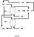
- This example shows the use of the system and method according to the invention for preparing a fresh dialysate for hemodialysis, cf. Figs. 3A and 3B .
- the reservior for the fresh and ready-to-use dialysate (301) holds a start volume of dialysate prepared beforehand.
- the fresh and ready-to-use dialysate (301) enters the dialyzer.
- the now spent dialysate (302) comprises ions (Na+, K+, lactate, acetate, bicarbonate, etc.), low molecular weight metabolites (e.g. urea) other metabolites (indoxyl, beta-2-microglobulin, etc.) and water.
- the spent dialysate enters the first forward osmosis (FO) unit (307) on the feed side of the membrane.
- FO forward osmosis
- the bicarbonate concentrate On the draw side of the membrane of this first FO unit runs the bicarbonate concentrate (305).
- the bicarbonate concentrate becomes diluted with water absorbed through the FO membrane from the spent dialysate.
- the spent dialysate enters the second forward osmosis unit (308) on the feed side of the membrane.
- the acid concentrate (citrate, lactate, acetate) (306).
- the acid concentrate becomes diluted with water from the spent dialysate.
- the spent and dewatered dialysate (309) is discarded.
- the spent dialysate (302) enters the second forward osmosis unit (308) on the feed side of the membrane.
- the acid concentrate (citrate, lactate, acetate) (306).
- the acid concentrate becomes diluted with water from the spent dialysate.
- the spent and dewatered dialysate (309) is discarded.
- the diluted bicarbonate concentrate and the diluted acid concentrate are mixed and adjusted as needed with purified water to obtain a fresh dialysate of the desired concentration of acidic and basic components.
- Example 5 A water extraction system for recycling of hemodialysis water from spent dialysis solution
- This example shows the use of a highly water permeable FO membrane being essentially impermeable to salts and low molecular weight solutes in a water extraction process for post treatment of spent dialysate solutions, cf. Fig. 1 .
- the dialysate solution is typically a diluted aqueous solution of mineral ions and glucose, which typically runs in a counter-current flow with blood from a patient through a hollow fiber ultrafiltration module during hemodialysis.
- Sam et al. (2006) discloses composition and clinical use of hemodialysates.
- the dialysate solution will maintain a sufficient concentration gradient across an ultrafiltration membrane with respect to the solutes that have to be removed from the blood, such as urea, degradation products such as indoxyl sulphate and p-cresol, and excess potassium and phosphorous, and thus maintain efficiency of the dialysis.
- large quantities of ultrapure water are needed, i.a. about 400 L of water per week.
- the water extraction systems described herein are useful in systems for recycling of this ultrapure water, such as in a closed loop, where the (diluted) used or spent dialysate solution, after being used in hemodialysis, e.g.
- a hemodialysis filter after absorbing waste materials such as urea and other metabolites from blood by passing through a hemodialysis filter may function as the source or feed solution (101) when passing through an FO membrane module, or flow cell (102) containing an aquaporin membrane prepared a disclosed herein, and where a concentrated fresh dialysate solution (dialysis concentrate) may function as the draw solution (106).
- a concentrated fresh dialysate solution dialysis concentrate
- the concentrated dialysate can be sufficiently diluted so as to be directly used for continued hemodialysis (108).
- a supply of purified water may be used as a supplementary water source.
- Example 6 A water extraction system for re-use of water lost through peritoneal dialysis
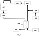
- Fig. 4 shows a system for continuous preparation of peritoneal dialysis fluid where a forward osmosis unit is used to extract pure water from spent peritoneal dialysis fluid.
- a forward osmosis unit is used to extract pure water from spent peritoneal dialysis fluid.
- This is an alternative to the use of multiple and high fill volume dialysate bags as used today and to using a supply of purified water from reverse osmosis and subsequent ultrafiltration, cf. Brunkhorst et al. (1998) who studied the feasibility of production of a dialysis fluid for peritoneal dialysis using a Gambro AK 100 Ultra machine which was developed for on-line production of intravenous substitution fluids for hemofiltration.
- the fresh dialysate for peritoneal dialysis is prepared from an acid concentrate (401) which flows through the draw side of the FO unit (402). On the feed side of the FO unit runs the spent dialysate from the patient (408).
- the diluted concentrate may optionally be further diluted from a supply of purified water (403), which water has undergone ultrafiltration in an ultrafiltration unit (404).
- the diluted concentrate then runs through a bicarbonate column (405) and then an ultrafiltration unit (406) before entering a reservior for fresh dialysate (407).
- the reservior (407) holds a start volume of fresh dialysate prepared beforehand.
- Re-using pure water obtained through FO extraction according to the invention herein adds additional benefits to the production of fresh dialysis fluids, because of elimination of the energy use necessary for the usual reverse osmosis and ultrafiltration processes in addition to other benefits, such as reduced dangers of toxic substance contamination etc.
- Example 7 A water extraction system for recycling of water lost through hemofiltration
- Hemofiltration is a renal replacement therapy used in intensive care, such as for acute renal failure. It is a slow continuous therapy in which sessions usually last between 12 to 24 hours and are usually performed daily.
- a patient's blood is passed via a machine to a semipermeable membrane (the hemofilter), typically an ultrafiltration membrane, for removal of waste products and excess water.
- the hemofilter typically an ultrafiltration membrane
- Hemofiltration rates such as 1 L/hr mean that one liter of fluid is removed from the patient's blood and eliminated in the drainage fluid and 1 L of replacement fluid is returned to the circuit before it reaches the patient.
- the solute movement from the blood is governed by convection rather than by diffusion thus avoiding the use of the hypertonic dialysate. Instead, a positive hydrostatic pressure drives water and solutes across the hemofilter membrane from the blood compartment to the filtrate compartment, from which it is drained. Solutes pass through the membrane at a similar rate by the flow of water forced by the hydrostatic pressure. Thus convection overcomes the reduced removal rate of larger solutes due to their slow speed of diffusion, which is seen in hemodialysis.
- the isotonic replacement fluid is added to the blood to replace lost fluid volume and electrolytes in the drainage.
- the replacement fluid must be of high purity, because it is infused directly into the blood line of the extracorporeal circuit. Replacement fluids can be returned either pre or post hemofilter.
- Predilution means that the replacement solution is returned to the blood before it reaches the filter, diluting the blood in the hollow fibers.
- Postdilution means that the replacement fluid is returned to the blood after the filter (but before the return side of the access catheter). Predilution dilutes the blood in the filter, reducing clotting. Postdilution concentrates the blood in the filter, enhancing clearance.
- the system of the invention (referring to Fig. 5A ) is useful in preparation of the replacement fluid by applying a relatively more concentrated solution (509) as the draw solution and applying the hemofiltrate drainage fluid (507) from the patient as the feed in a forward osmosis unit to obtain the proper isotonic replacement fluid using concentration adjustment measures as needed and passing through sterilization steps as needed.
- a supply of isotonic replacement fluid (511) may be used as a supplementary water source.
- the replacement fluids is returned post hemofilter.
- a commercial replacement fluid from Gambro, Hemosol B0 consists of a two compartment PVC bag containing an electrolyte solution in the small compartment (compartment A) and the buffer solution in the large compartment (compartment B).
- Either of the electrolyte and the buffer concentrate will be useful in the form of a concentrate as a draw solution in combination with the drainage fluid as the feed.
- a concentrate as a draw solution in combination with the drainage fluid as the feed.
- an electrolyte concentrate is the Normocarb HF TM series from Dialysis Solutions Inc: Undiluted Normocarb HF TM 25 contains 90.73 g/L sodium chloride, 2.06 g/L magnesium chloride hexahydrate and 28.35 g/L sodium bicarbonate in water for injection. Undiluted Normocarb HF TM 35 contains 82.84 g/L sodium chloride, 2.06 g/L magnesium chloride hexahydrate and 39.70 g/L sodium bicarbonate in water for injection. Both concentrates are to be diluted 13.5 times before use.
- the filtrate, such as a microfiltrate or an ultrafiltrate, from hemofiltration can be shunted through a renal assist device (RAD) for re-extraction of water, cf. Issa et al. (2007), where said device is in the form of a hollow fiber unit having an active layer comprising aquaporin water channels, such as hollow fibres modified with a thin film composite layer comprising aquaporin water channels prepared as described above. Said device is shown as (506) in Fig. 5B , 5C, and 5D . All of Figs. 5A to 5D are adapted from Issa et al.
- RAD renal assist device
- Fig. 5B shows a schematic hemofiltration setting for re-extraction of water from the filtrate (507) emanating from the hemofilter (502), which in this case is a HF module with the blood stream under hydrostatic pressure running inside the hollow microporous fibres. Subsequent to passage through the hemofilter the now concentrated blood runs through the extracapillary space or shellside of an HF module (506) co- or counter-current with the filtrate that runs in the lumen side of the hollow fibres under forward osmosis conditions or under pressure (by pumping) assisted forward osmosis.
- the hemofilter which in this case is a HF module with the blood stream under hydrostatic pressure running inside the hollow microporous fibres.
- Fig. 5C shows a schematic hemofiltration setting comparable to Fig. 5A , but where a predilutional replacement fluid stream (512) enters the hemofilter.
- Fig. 5D shows a schematic hemofiltration setting where a postdilutional replacement fluid stream (513) enters the filtered blood steam directly following re-extraction of water from the hemofiltrate.
- An example of a commercial hemofiltration unit is Prismaflex M150 Set from Gambro having an active filter area of 1.5 m 2 .
- the hollow fiber internal diameter (wet) is 240 ⁇ m, and fiber wall thickness is 50 ⁇ m.
- Nipro's hollow fiber hemofilter UF-205 wherein the inner fibre membrane is made from triacetate, with a diameter of 200 ⁇ m and a thickness of 15 ⁇ m.
- the outer casing is made from polycarbonate and polyurethane, sterilized with gamma radiation.
- the unit is designed to withstand pressures up to 500 mmHg,
- high molecular composite membrane polysulfone fibers may be used having a pore diameter of 0.005 ⁇ m - 0.05 ⁇ m. These and similar hollow fibers may be used in FO modules for reabsorption of water from filtrates or spent fluids from renal replacement therapy processes, and said fibers may be modified with a thin film composite membrane having incorporated aquaporin water channels for enhanced water flux and selectivity.
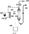
- Fig. 5E shows how a system similar to the system from Fig. 5A works with pumps (514, 515, 516) for pumping the blod to the hemofilter (pump 514), the filtrate through the forward osmosis (FO) module (pump 515) and the electrolyte containing replacement concentrate through the FO module (pump 516).
- the system of Fig. 5E works with predilution of the blood.
- the pump (516) may also yield a hydraulic pressure to provide an assisted forward osmosis in the module (506).
- Cycle 1 feed (302), chamber (307), up concentrated feed (309), draw (305), the FO chamber (307) and the diluted draw (301).
- the feed solution is an artificially prepared spent dialysate solution (302) containing: urea, creatinine, o-cresol, p-cresol, indoxyl acetate/sulfate and beta-microglobulin. It is made up to a concentration resulting in a typical concentration found in blood to result in 0.3 Osmol/L. The osmolality of the feed solution is measured by Osmomat 030, Gonotec GmbH.
- the concentrated basic draw solution (305) is a 1 mol/L bicarbonate solution. It is made up to an osmolality of 1.7 Osmol /L corresponding to an osmotic pressure of 40 bars.
- the FO experiments are performed with a bench-scale membrane system consisting of a CF042 Cell (Sterlitech, Kent, WA) as the cross flow membrane filtration unit.
- a bench-scale membrane system consisting of a CF042 Cell (Sterlitech, Kent, WA) as the cross flow membrane filtration unit.
- the FO membrane for example an Aquaporin Inside TM FO membrane (42cm 2 ) is placed with the active side facing the feed.
- a 500mL feed solution reservoir and a 500mL stirred draw solution reservoir are connected to the membrane cell.
- the solutions are pumped in counter-current flow at 50 mL/min with one peristaltic pump (BT100-1L, Longer Pump, China).
- the feed reservoir is placed on a digital scale (Kern 572, Kern & Sohn GmbH, Germany) and a conductivity probe is installed in the feed circuit (Orion 3 star meter - 013016MD probe, Thermo Scientific, Waltham, MA).
- a computer monitors the measurements to calculate an online water flux and reverse salt flux.
- Manual samples are taken from the draw solution to measure the rejection of the organic compounds from the feed solution, which are being determined by common analytical tools/methods like HPLC after solid phase extraction.
- Previous unpublished test results have shown a >95-99 % rejection of creatinine in a similar FO setup, but with the use of a hollow fiber Aquaporin Inside TM FO module.
- Cycle 2 feed (302), chamber (308), up concentrated feed (309), draw (306), the FO chamber (308) and the diluted draw (301).
- the feed solution is an artificially prepared spent dialysate solution described above.
- the draw solution (306) is an acid concentrate, e.g. made up according to the compounds and concentrations given in table 4.
- connection of the feed, draw and the monitoring of the experiment is performed similar to the set-up in chamber (307).
- the acid and the base dialysate solutions having been diluted with pure water extracted from the feed during the FO processes are combined and a purified water source is used to adjust the osmolality to the needed hypertonicity for use in a hemodialysis setting.
- Analysis of samples from each of the two diluted draw solutions are expected to prove very high rejections of the analytes, e.g. : urea, creatinine, o-cresol, p-cresol, indoxyl acetate/sulfate and beta-microglobulin.
- feed hemofiltrate drainage fluid
- draw concentrated replacement fluid
- FO chamber FO chamber
- diluted draw 510
- the feed solution is an hemofiltrate drainage fluid (507) obtained from an intensive care unit.
- the osmolality of the feed solution is measured by Osmomat 030, Gonotec GmbH.
- the concentrated replacement fluid (509) is a solution containing 90.73 g/L sodium chloride, 2.06 g/L magnesium chloride hexahydrate and 28.35 g/L sodium bicarbonate. It corresponds to an osmotic pressure of about 108 bar, cf. Example 1b.
- the FO experiments are performed with a bench-scale membrane system consisting of a CF042 Cell (Sterlitech, Kent, WA) as the cross flow membrane filtration unit.
- a bench-scale membrane system consisting of a CF042 Cell (Sterlitech, Kent, WA) as the cross flow membrane filtration unit.
- the FO membrane for example an Aquaporin Inside TM FO membrane (42cm 2 ) is placed with the active side facing the feed.
- a 500mL feed solution reservoir and a 500mL stirred draw solution reservoir are connected to the membrane cell.
- the solutions are pumped in counter-current flow at 50 mL/min with one peristaltic pump (BT100-1L, Longer Pump, China).
- the feed reservoir is placed on a digital scale (Kern 572, Kern & Sohn GmbH, Germany) and a conductivity probe is installed in the feed circuit (Orion 3 star meter - 013016MD probe, Thermo Scientific, Waltham, MA).
- a computer monitors the measurements to calculate an online water flux and reverse salt flux. Manual samples are taken from the draw solution to measure the rejection of the organic compounds from the feed solution, which are being determined by common analytical tools/methods like HPLC after solid phase extraction.
- a set-up with an Aquaporin Inside TM hollow fiber FO module can be used.
Landscapes
- Health & Medical Sciences (AREA)
- Heart & Thoracic Surgery (AREA)
- Engineering & Computer Science (AREA)
- Life Sciences & Earth Sciences (AREA)
- Public Health (AREA)
- General Health & Medical Sciences (AREA)
- Veterinary Medicine (AREA)
- Vascular Medicine (AREA)
- Anesthesiology (AREA)
- Biomedical Technology (AREA)
- Hematology (AREA)
- Animal Behavior & Ethology (AREA)
- Chemical & Material Sciences (AREA)
- Chemical Kinetics & Catalysis (AREA)
- Water Supply & Treatment (AREA)
- Urology & Nephrology (AREA)
- Biochemistry (AREA)
- Molecular Biology (AREA)
- Dispersion Chemistry (AREA)
- Emergency Medicine (AREA)
- External Artificial Organs (AREA)
- Separation Using Semi-Permeable Membranes (AREA)
Claims (6)
- Hämofiltrationsmaschine, die ein System zur Nutzung der Abfallflüssigkeit aus einem Hämofilter (502)zur Wiederverwendung mindestens eines Teils des Wassergehalts in der Abfallflüssigkeit aus einem Hämofiltrationsverfahren umfasst, wobei das System einen Hämofilter (502) mit einem Filtratauslass für eine Abfallflüssigkeit (507), die das Filtrat aus dem Hämofilter ist, und einen Konzentratauslass für das Konzentrat aus dem Hämofilter (505) umfasst, eine Quelle für Elektrolytersatzkonzentrat (509) und eine Vorwärtsosmose(FO)-Einheit (102, 506), die eine Vorwärtsosmosemembran (103) mit nanoporösen Wasserkanälen umfasst, wobei die Membran eine Zufuhrseite (104) und eine Abzugsseite (105) aufweist, wobei der Filtratauslass des Hämofilters in Fluidverbindung mit der Zufuhrseite der FO-Einheit steht, und wobei die Quelle des Elektrolytersatzkonzentrats (509) oder der Konzentratauslass des Hämofilters in Fluidverbindung mit der Abzugsseite der FO-Einheit steht, wobei die nanoporösen Wasserkanäle Aquaporinwasserkanäle sind, wobei die Membran eine aktive Schicht umfasst, die immobilisierte Aquaporinwasserkanäle und eine Trägerschicht enthält, und wobei die aktive Schicht eine Dünnfilmverbund-(TFC)-Membran umfasst.
- Hämofiltrationsmaschine nach Anspruch 1, wobei das System ferner Mittel zum Pumpen der Abfallflüssigkeit (515, 507) und das Elektrolytersatzkonzentrat (516, 509) umfasst.
- Hämofiltrationsmaschine nach Anspruch 1, wobei die aktive Schicht eine vernetzte aromatische Amidschicht ist, die vorzugsweise durch Grenzflächenpolymerisation gebildet wird, wobei Aquaporin-Vesikel inkorporiert werden, wobei die Vesikel durch Selbstorganisation von amphiphilen matrixbildenden Verbindungen in Gegenwart einer Aquaporinproteinpräparation gebildet werden.
- Hämofiltrationsmaschine nach Anspruch 1, wobei amphiphile matrixbildende Verbindungen aus amphiphilem Lipid, Hydrophobin, Deblock-Copolymer, Triblock-Copolymer oder Mischungen davon ausgewählt werden.
- Hämofiltrationsmaschine nach einem der Ansprüche 1 bis 4, wobei der Aquaporin-Wasserkanal aus Aquaporinen prokaryotischen Ursprungs, z. B. AqpZ; Säugetier-Aquaporinen, z. B. Aqp1 und Aqp2; pflanzlichen Aquaporinen, einschließlich Plasma-intrinsischer Proteine (PIP), Tonoplastintrinsischer Proteine (TIP), Nodulin-intrinsischer Proteine (NIP) und kleiner intrinsischer Proteine (SIP), z. B. SoPIP2;1, PttPIP2;5 und PtPIP2;2; Hefe-Aquaporine, z. B. AQY1 und AQY2; sowie Aquaglyceroporinen wie GlpF und Yfl054 ausgewählt wird.
- Hämofiltrationsmaschine nach einem der Ansprüche 1 bis 5, ferner umfassend Mittel zur Druckbeaufschlagung der Abfallflüssigkeit, die zu einem druckunterstützten Vorwärtsosmoseprozess führt.
Applications Claiming Priority (3)
| Application Number | Priority Date | Filing Date | Title |
|---|---|---|---|
| PCT/EP2014/053519 WO2014128293A1 (en) | 2013-02-25 | 2014-02-24 | Systems for water extraction |
| DKPA201400398A DK179128B1 (en) | 2014-02-24 | 2014-07-17 | Systems for utilizing the water content in fluid from a renal replacement therapy process |
| PCT/EP2015/053598 WO2015124716A1 (en) | 2014-02-24 | 2015-02-20 | Systems for utilizing the water content in fluid from a renal replacement therapy process |
Publications (3)
| Publication Number | Publication Date |
|---|---|
| EP3110532A1 EP3110532A1 (de) | 2017-01-04 |
| EP3110532C0 EP3110532C0 (de) | 2024-01-10 |
| EP3110532B1 true EP3110532B1 (de) | 2024-01-10 |
Family
ID=53877650
Family Applications (1)
| Application Number | Title | Priority Date | Filing Date |
|---|---|---|---|
| EP15708755.2A Active EP3110532B1 (de) | 2014-02-24 | 2015-02-20 | Systeme zur verwendung des wassergehalts in einer flüssigkeit aus einem nierenersatztherapieverfahren |
Country Status (7)
| Country | Link |
|---|---|
| US (1) | US10293094B2 (de) |
| EP (1) | EP3110532B1 (de) |
| CN (1) | CN106573094B (de) |
| DK (1) | DK179128B1 (de) |
| ES (1) | ES2974276T3 (de) |
| PL (1) | PL3110532T3 (de) |
| WO (1) | WO2015124716A1 (de) |
Families Citing this family (40)
| Publication number | Priority date | Publication date | Assignee | Title |
|---|---|---|---|---|
| WO2014063097A1 (en) | 2012-10-19 | 2014-04-24 | Danisco Us Inc. | Stabilization of biomimetic membranes |
| DK177696B1 (en) | 2013-02-25 | 2014-03-17 | Aquaporin As | Systems for water extraction |
| DK179128B1 (en) | 2014-02-24 | 2017-11-20 | Aquaporin As | Systems for utilizing the water content in fluid from a renal replacement therapy process |
| JP6575249B2 (ja) * | 2014-09-19 | 2019-09-18 | 東洋紡株式会社 | 人工透析液の製造方法および人工透析液製造システム |
| AU2016363021A1 (en) * | 2015-12-04 | 2018-05-31 | Qidni Labs, Inc. | An implantable renal replacement therapy |
| US10406270B2 (en) * | 2015-12-31 | 2019-09-10 | Baxter International Inc. | Devices for urea electrolysis with combination electrodialysis and urea oxidation cell and methods of using same |
| US10391222B2 (en) | 2015-12-31 | 2019-08-27 | Baxter International Inc. | Devices for urea electrolysis and methods of using same |
| US10463776B2 (en) | 2015-12-31 | 2019-11-05 | Baxter International Inc. | Methods and apparatuses using urea permselective diffusion through charged membranes |
| US12059654B2 (en) | 2016-02-08 | 2024-08-13 | Aquaporin A/S | Self-assembled nanostructures and separation membranes comprising aquaporin water channels and methods of making and using them |
| MA38915B2 (fr) * | 2016-03-21 | 2018-10-31 | Univ Hassan Ii | Dispositif portable pour hémodialyse |
| US10150094B2 (en) | 2016-06-09 | 2018-12-11 | King Fahd University Of Petroleum And Minerals | Metal adsorbent and a method of making thereof |
| DE102016010434B4 (de) * | 2016-08-27 | 2024-07-04 | Fresenius Medical Care Deutschland Gmbh | Blutbehandlungsvorrichtung |
| JP6980992B2 (ja) * | 2016-10-05 | 2021-12-15 | Jfeエンジニアリング株式会社 | 水処理方法および水処理装置 |
| EP3538252A1 (de) | 2016-11-11 | 2019-09-18 | Aquaporin A/S | Selbstangeordnete polymere vesikelstrukturen mit funktionellen molekülen |
| US10561778B2 (en) * | 2017-03-02 | 2020-02-18 | Fresenius Medical Care Holdings, Inc. | Split reservoir bags and method of using split reservoir bags to improve the heating and generation of dialysate |
| ES2629163B1 (es) * | 2017-03-30 | 2017-12-01 | Grifols Worldwide Operations Limited | Dispositivo de recambio plasmático terapéutico |
| CN106932561B (zh) * | 2017-05-09 | 2019-07-19 | 青岛市城阳区人民医院 | 一种血液透析仪中自动检测水分装置 |
| US10881347B2 (en) | 2017-12-29 | 2021-01-05 | Fresenius Medical Care Holdings, Inc. | Closed loop dialysis treatment using adaptive ultrafiltration rates |
| DE102018105120A1 (de) * | 2018-03-06 | 2019-09-12 | Fresenius Medical Care Deutschland Gmbh | Vorrichtung und Verfahren zur Regeneration einer Dialyselösung |
| DE102018118564A1 (de) * | 2018-07-31 | 2020-02-06 | Fresenius Medical Care Deutschland Gmbh | Vorrichtung und Verfahren zur Herstellung einer Dialyselösung |
| CN109646743A (zh) * | 2019-01-07 | 2019-04-19 | 哈尔滨工业大学(威海) | 一种血液透析废水回用的方法 |
| PL3930877T3 (pl) * | 2019-02-28 | 2024-01-03 | Aquaporin A/S | Wytwarzanie stężonego zużytego dializatu |
| EP3946700A4 (de) * | 2019-03-29 | 2023-05-24 | Khalifa University of Science and Technology | Kontrollierte nanoskalig-perforierte zweidimensionale materialien und membranen |
| EP3960218B1 (de) * | 2019-04-26 | 2025-05-07 | Toray Industries, Inc. | Verfahren zur regeneration einer dialyselösung |
| US12350039B2 (en) * | 2019-05-10 | 2025-07-08 | Bal CHANDER | Blood analysis system |
| CN112245691B (zh) * | 2019-07-22 | 2024-07-05 | 巴克斯特医疗保健股份有限公司 | 从原水制备透析液的方法和系统 |
| CN110606589A (zh) * | 2019-09-24 | 2019-12-24 | 杭州师范大学附属医院(杭州市第二人民医院) | 一种节水型血液透析用水制备系统 |
| DE102020106749A1 (de) | 2020-01-28 | 2021-07-29 | Fresenius Medical Care Deutschland Gmbh | Vorrichtung und Verfahren zur Herstellung von Dialysat |
| CN115038473A (zh) | 2020-01-28 | 2022-09-09 | 费森尤斯医疗护理德国有限责任公司 | 用于制备透析液的设备和方法 |
| CN115087472B (zh) | 2020-02-06 | 2025-10-17 | 甘布罗伦迪亚股份公司 | 用于产生用于腹膜透析的流体的系统和方法 |
| EP4100077A1 (de) * | 2020-02-06 | 2022-12-14 | Gambro Lundia AB | System und verfahren zur herstellung von flüssigkeit für die peritonealdialyse |
| EP3900755A1 (de) | 2020-04-22 | 2021-10-27 | Ceinge Biotecnologie Avanzate SCarl | Integrierte plattform für plasmapherese, hämofiltration, rezirkulation und plasmakonzentration für die pathogendiagnose und andere biomedizinische anwendungen |
| EP4291323A1 (de) * | 2021-02-11 | 2023-12-20 | Sani Membranes A/S | Filtervorrichtung |
| WO2022216604A1 (en) * | 2021-04-06 | 2022-10-13 | University Of Washington | Dialysis system incorporating a toxin-removal loop |
| CN117120117A (zh) * | 2021-04-09 | 2023-11-24 | 甘布罗伦迪亚股份公司 | 正向渗透单元的灌注 |
| JP7840984B2 (ja) * | 2021-04-09 | 2026-04-06 | ガンブロ・ルンディア・エービー | 正浸透を使用する透析液の効率的な生成のための装置及び方法 |
| WO2022214447A1 (en) * | 2021-04-09 | 2022-10-13 | Gambro Lundia Ab | Priming of a forward osmosis unit |
| US20240382659A1 (en) * | 2021-04-09 | 2024-11-21 | Gambro Lundia Ab | Evaluating integrity of a forward osmosis membrane during continuous flow |
| US20250025836A1 (en) * | 2021-11-30 | 2025-01-23 | Toray Industries, Inc. | Solution treatment method and solution treatment unit |
| CN121466829A (zh) * | 2026-01-06 | 2026-02-06 | 四川大学 | 一种高通量薄膜复合膜、其制备方法及其应用 |
Citations (2)
| Publication number | Priority date | Publication date | Assignee | Title |
|---|---|---|---|---|
| WO2010091078A2 (en) * | 2009-02-03 | 2010-08-12 | Danfoss Aquaz A/S | Nanofabricated membrane using polymerized proteoliposomes |
| WO2013043118A1 (en) * | 2011-09-21 | 2013-03-28 | Nanyang Technological University | Aquaporin based thin film composite membranes |
Family Cites Families (18)
| Publication number | Priority date | Publication date | Assignee | Title |
|---|---|---|---|---|
| US4277344A (en) | 1979-02-22 | 1981-07-07 | Filmtec Corporation | Interfacially synthesized reverse osmosis membrane |
| US4734198A (en) * | 1984-02-06 | 1988-03-29 | Minntech Corporation | Dialysis solution mixing system |
| DE19540079C2 (de) * | 1995-10-27 | 2000-06-21 | Joachim Boehler | Dialysegerät |
| CN2416090Y (zh) * | 2000-02-28 | 2001-01-24 | 杨跃平 | 便携式正渗透净水器 |
| US20030073945A1 (en) * | 2001-10-17 | 2003-04-17 | Liang-Kuang Diang | Ozone hemodiafiltration device |
| JP4123230B2 (ja) * | 2002-07-12 | 2008-07-23 | セイコーエプソン株式会社 | 血液中水分量検出装置及び血液透析時期判定装置 |
| WO2009083011A2 (en) * | 2007-12-30 | 2009-07-09 | Mohamed Fahim Khaled Mohamed T | A method for dialysis fluid regeneration |
| US8298167B2 (en) | 2008-11-03 | 2012-10-30 | B. Braun Avitum Ag | Modular hemofiltration apparatus with interactive operator instructions and control system |
| DK177144B1 (en) * | 2009-06-19 | 2012-02-06 | Aquaporin As | A liquid membrane suitable for water extraction |
| CN103140278B (zh) | 2010-09-30 | 2015-06-10 | 海绵股份有限公司 | 用于正向渗透的薄膜复合膜及其制备方法 |
| DK177307B1 (en) * | 2010-12-17 | 2012-11-12 | Aquaporin As | A liquid membrane |
| WO2012102678A1 (en) * | 2011-01-24 | 2012-08-02 | Nano-Mem Pte. Ltd. | A forward osmosis membrane |
| US20150136690A1 (en) * | 2012-06-01 | 2015-05-21 | National Unibersity of Singapore | Method of making a membrane and a membrane for water filtration |
| WO2014075086A1 (en) | 2012-11-12 | 2014-05-15 | Nagare Membranes, Llc | Methods for reducing ion exchange and reverse salt flux phenomena in membranes for osmotically driven membrane processes |
| GB201300465D0 (en) | 2013-01-11 | 2013-02-27 | Aquaporin As | A hollow fiber module having tfc-aquaporin modified membranes |
| DK177696B1 (en) * | 2013-02-25 | 2014-03-17 | Aquaporin As | Systems for water extraction |
| US20140255636A1 (en) * | 2013-03-06 | 2014-09-11 | Saudi Basic Industries Corporation | Polymeric Membranes |
| DK179128B1 (en) | 2014-02-24 | 2017-11-20 | Aquaporin As | Systems for utilizing the water content in fluid from a renal replacement therapy process |
-
2014
- 2014-07-17 DK DKPA201400398A patent/DK179128B1/en not_active IP Right Cessation
-
2015
- 2015-02-20 US US15/121,179 patent/US10293094B2/en active Active
- 2015-02-20 CN CN201580010310.4A patent/CN106573094B/zh active Active
- 2015-02-20 WO PCT/EP2015/053598 patent/WO2015124716A1/en not_active Ceased
- 2015-02-20 EP EP15708755.2A patent/EP3110532B1/de active Active
- 2015-02-20 PL PL15708755.2T patent/PL3110532T3/pl unknown
- 2015-02-20 ES ES15708755T patent/ES2974276T3/es active Active
Patent Citations (2)
| Publication number | Priority date | Publication date | Assignee | Title |
|---|---|---|---|---|
| WO2010091078A2 (en) * | 2009-02-03 | 2010-08-12 | Danfoss Aquaz A/S | Nanofabricated membrane using polymerized proteoliposomes |
| WO2013043118A1 (en) * | 2011-09-21 | 2013-03-28 | Nanyang Technological University | Aquaporin based thin film composite membranes |
Non-Patent Citations (1)
| Title |
|---|
| YANG ZHAO ET AL: "Synthesis of robust and high-performance aquaporin-based biomimetic membranes by interfacial polymerization-membrane preparation and RO performance characterization", JOURNAL OF MEMBRANE SCIENCE, vol. 423-424, 1 December 2012 (2012-12-01), pages 422 - 428, XP055107663, ISSN: 0376-7388, DOI: 10.1016/j.memsci.2012.08.039 * |
Also Published As
| Publication number | Publication date |
|---|---|
| PL3110532T3 (pl) | 2024-04-29 |
| CN106573094B (zh) | 2020-06-05 |
| EP3110532C0 (de) | 2024-01-10 |
| EP3110532A1 (de) | 2017-01-04 |
| US10293094B2 (en) | 2019-05-21 |
| US20170065762A1 (en) | 2017-03-09 |
| CN106573094A (zh) | 2017-04-19 |
| ES2974276T3 (es) | 2024-06-26 |
| DK201400398A1 (en) | 2015-11-30 |
| DK179128B1 (en) | 2017-11-20 |
| WO2015124716A1 (en) | 2015-08-27 |
Similar Documents
| Publication | Publication Date | Title |
|---|---|---|
| EP3110532B1 (de) | Systeme zur verwendung des wassergehalts in einer flüssigkeit aus einem nierenersatztherapieverfahren | |
| JP5946591B2 (ja) | 薄層複合アクアポリン修飾膜を有する中空繊維モジュール | |
| EP3930877B1 (de) | Herstellung von konzentriertem verbrauchtem dialysat | |
| US10322221B2 (en) | Removal of carbon dioxide via dialysis | |
| WO2009083011A2 (en) | A method for dialysis fluid regeneration | |
| WO2021016188A2 (en) | Method and system for preparing dialysis fluid from raw water | |
| KR102400189B1 (ko) | 정삼투 기반 투석액 재생 장치 및 착용 형 인공 신장 장치 | |
| CN203694922U (zh) | 具有薄膜复合物-水通道蛋白改性膜的中空纤维组件 | |
| Hamilton | Principles of dialysis: diffusion, convection, and dialysis machines | |
| KR200477157Y1 (ko) | Tfc-아쿠아포린 개질된 막을 갖는 중공섬유 모듈 | |
| JP6337175B2 (ja) | 急性又は慢性腎不全患者の血液からタンパク質結合毒素を除去するための透析法に使用される医薬組成物。 | |
| HK1217007B (en) | A hollow fiber module having thin film composite- aquaporin modified membranes |
Legal Events
| Date | Code | Title | Description |
|---|---|---|---|
| STAA | Information on the status of an ep patent application or granted ep patent |
Free format text: STATUS: THE INTERNATIONAL PUBLICATION HAS BEEN MADE |
|
| PUAI | Public reference made under article 153(3) epc to a published international application that has entered the european phase |
Free format text: ORIGINAL CODE: 0009012 |
|
| STAA | Information on the status of an ep patent application or granted ep patent |
Free format text: STATUS: REQUEST FOR EXAMINATION WAS MADE |
|
| 17P | Request for examination filed |
Effective date: 20160712 |
|
| AK | Designated contracting states |
Kind code of ref document: A1 Designated state(s): AL AT BE BG CH CY CZ DE DK EE ES FI FR GB GR HR HU IE IS IT LI LT LU LV MC MK MT NL NO PL PT RO RS SE SI SK SM TR |
|
| AX | Request for extension of the european patent |
Extension state: BA ME |
|
| DAX | Request for extension of the european patent (deleted) | ||
| STAA | Information on the status of an ep patent application or granted ep patent |
Free format text: STATUS: EXAMINATION IS IN PROGRESS |
|
| 17Q | First examination report despatched |
Effective date: 20190923 |
|
| GRAP | Despatch of communication of intention to grant a patent |
Free format text: ORIGINAL CODE: EPIDOSNIGR1 |
|
| STAA | Information on the status of an ep patent application or granted ep patent |
Free format text: STATUS: GRANT OF PATENT IS INTENDED |
|
| INTG | Intention to grant announced |
Effective date: 20230814 |
|
| GRAS | Grant fee paid |
Free format text: ORIGINAL CODE: EPIDOSNIGR3 |
|
| GRAA | (expected) grant |
Free format text: ORIGINAL CODE: 0009210 |
|
| STAA | Information on the status of an ep patent application or granted ep patent |
Free format text: STATUS: THE PATENT HAS BEEN GRANTED |
|
| AK | Designated contracting states |
Kind code of ref document: B1 Designated state(s): AL AT BE BG CH CY CZ DE DK EE ES FI FR GB GR HR HU IE IS IT LI LT LU LV MC MK MT NL NO PL PT RO RS SE SI SK SM TR |
|
| REG | Reference to a national code |
Ref country code: GB Ref legal event code: FG4D |
|
| REG | Reference to a national code |
Ref country code: CH Ref legal event code: EP |
|
| REG | Reference to a national code |
Ref country code: DE Ref legal event code: R096 Ref document number: 602015087222 Country of ref document: DE |
|
| REG | Reference to a national code |
Ref country code: IE Ref legal event code: FG4D |
|
| U01 | Request for unitary effect filed |
Effective date: 20240207 |
|
| U07 | Unitary effect registered |
Designated state(s): AT BE BG DE DK EE FI FR IT LT LU LV MT NL PT SE SI Effective date: 20240215 |
|
| U20 | Renewal fee for the european patent with unitary effect paid |
Year of fee payment: 10 Effective date: 20240515 |
|
| REG | Reference to a national code |
Ref country code: ES Ref legal event code: FG2A Ref document number: 2974276 Country of ref document: ES Kind code of ref document: T3 Effective date: 20240626 |
|
| PG25 | Lapsed in a contracting state [announced via postgrant information from national office to epo] |
Ref country code: IS Free format text: LAPSE BECAUSE OF FAILURE TO SUBMIT A TRANSLATION OF THE DESCRIPTION OR TO PAY THE FEE WITHIN THE PRESCRIBED TIME-LIMIT Effective date: 20240510 |
|
| PG25 | Lapsed in a contracting state [announced via postgrant information from national office to epo] |
Ref country code: GR Free format text: LAPSE BECAUSE OF FAILURE TO SUBMIT A TRANSLATION OF THE DESCRIPTION OR TO PAY THE FEE WITHIN THE PRESCRIBED TIME-LIMIT Effective date: 20240411 |
|
| PG25 | Lapsed in a contracting state [announced via postgrant information from national office to epo] |
Ref country code: HR Free format text: LAPSE BECAUSE OF FAILURE TO SUBMIT A TRANSLATION OF THE DESCRIPTION OR TO PAY THE FEE WITHIN THE PRESCRIBED TIME-LIMIT Effective date: 20240110 Ref country code: RS Free format text: LAPSE BECAUSE OF FAILURE TO SUBMIT A TRANSLATION OF THE DESCRIPTION OR TO PAY THE FEE WITHIN THE PRESCRIBED TIME-LIMIT Effective date: 20240410 |
|
| PG25 | Lapsed in a contracting state [announced via postgrant information from national office to epo] |
Ref country code: RS Free format text: LAPSE BECAUSE OF FAILURE TO SUBMIT A TRANSLATION OF THE DESCRIPTION OR TO PAY THE FEE WITHIN THE PRESCRIBED TIME-LIMIT Effective date: 20240410 Ref country code: NO Free format text: LAPSE BECAUSE OF FAILURE TO SUBMIT A TRANSLATION OF THE DESCRIPTION OR TO PAY THE FEE WITHIN THE PRESCRIBED TIME-LIMIT Effective date: 20240410 Ref country code: IS Free format text: LAPSE BECAUSE OF FAILURE TO SUBMIT A TRANSLATION OF THE DESCRIPTION OR TO PAY THE FEE WITHIN THE PRESCRIBED TIME-LIMIT Effective date: 20240510 Ref country code: HR Free format text: LAPSE BECAUSE OF FAILURE TO SUBMIT A TRANSLATION OF THE DESCRIPTION OR TO PAY THE FEE WITHIN THE PRESCRIBED TIME-LIMIT Effective date: 20240110 Ref country code: GR Free format text: LAPSE BECAUSE OF FAILURE TO SUBMIT A TRANSLATION OF THE DESCRIPTION OR TO PAY THE FEE WITHIN THE PRESCRIBED TIME-LIMIT Effective date: 20240411 |
|
| REG | Reference to a national code |
Ref country code: CH Ref legal event code: PL |
|
| REG | Reference to a national code |
Ref country code: DE Ref legal event code: R097 Ref document number: 602015087222 Country of ref document: DE |
|
| PG25 | Lapsed in a contracting state [announced via postgrant information from national office to epo] |
Ref country code: SM Free format text: LAPSE BECAUSE OF FAILURE TO SUBMIT A TRANSLATION OF THE DESCRIPTION OR TO PAY THE FEE WITHIN THE PRESCRIBED TIME-LIMIT Effective date: 20240110 |
|
| PG25 | Lapsed in a contracting state [announced via postgrant information from national office to epo] |
Ref country code: CH Free format text: LAPSE BECAUSE OF NON-PAYMENT OF DUE FEES Effective date: 20240229 |
|
| PG25 | Lapsed in a contracting state [announced via postgrant information from national office to epo] |
Ref country code: CZ Free format text: LAPSE BECAUSE OF FAILURE TO SUBMIT A TRANSLATION OF THE DESCRIPTION OR TO PAY THE FEE WITHIN THE PRESCRIBED TIME-LIMIT Effective date: 20240110 |
|
| PG25 | Lapsed in a contracting state [announced via postgrant information from national office to epo] |
Ref country code: SK Free format text: LAPSE BECAUSE OF FAILURE TO SUBMIT A TRANSLATION OF THE DESCRIPTION OR TO PAY THE FEE WITHIN THE PRESCRIBED TIME-LIMIT Effective date: 20240110 |
|
| PG25 | Lapsed in a contracting state [announced via postgrant information from national office to epo] |
Ref country code: SM Free format text: LAPSE BECAUSE OF FAILURE TO SUBMIT A TRANSLATION OF THE DESCRIPTION OR TO PAY THE FEE WITHIN THE PRESCRIBED TIME-LIMIT Effective date: 20240110 Ref country code: SK Free format text: LAPSE BECAUSE OF FAILURE TO SUBMIT A TRANSLATION OF THE DESCRIPTION OR TO PAY THE FEE WITHIN THE PRESCRIBED TIME-LIMIT Effective date: 20240110 Ref country code: RO Free format text: LAPSE BECAUSE OF FAILURE TO SUBMIT A TRANSLATION OF THE DESCRIPTION OR TO PAY THE FEE WITHIN THE PRESCRIBED TIME-LIMIT Effective date: 20240110 Ref country code: CZ Free format text: LAPSE BECAUSE OF FAILURE TO SUBMIT A TRANSLATION OF THE DESCRIPTION OR TO PAY THE FEE WITHIN THE PRESCRIBED TIME-LIMIT Effective date: 20240110 Ref country code: CH Free format text: LAPSE BECAUSE OF NON-PAYMENT OF DUE FEES Effective date: 20240229 |
|
| PG25 | Lapsed in a contracting state [announced via postgrant information from national office to epo] |
Ref country code: MC Free format text: LAPSE BECAUSE OF FAILURE TO SUBMIT A TRANSLATION OF THE DESCRIPTION OR TO PAY THE FEE WITHIN THE PRESCRIBED TIME-LIMIT Effective date: 20240110 |
|
| PLBE | No opposition filed within time limit |
Free format text: ORIGINAL CODE: 0009261 |
|
| STAA | Information on the status of an ep patent application or granted ep patent |
Free format text: STATUS: NO OPPOSITION FILED WITHIN TIME LIMIT |
|
| PG25 | Lapsed in a contracting state [announced via postgrant information from national office to epo] |
Ref country code: MC Free format text: LAPSE BECAUSE OF FAILURE TO SUBMIT A TRANSLATION OF THE DESCRIPTION OR TO PAY THE FEE WITHIN THE PRESCRIBED TIME-LIMIT Effective date: 20240110 |
|
| 26N | No opposition filed |
Effective date: 20241011 |
|
| GBPC | Gb: european patent ceased through non-payment of renewal fee |
Effective date: 20240410 |
|
| PG25 | Lapsed in a contracting state [announced via postgrant information from national office to epo] |
Ref country code: GB Free format text: LAPSE BECAUSE OF NON-PAYMENT OF DUE FEES Effective date: 20240410 |
|
| PG25 | Lapsed in a contracting state [announced via postgrant information from national office to epo] |
Ref country code: IE Free format text: LAPSE BECAUSE OF NON-PAYMENT OF DUE FEES Effective date: 20240220 |
|
| PG25 | Lapsed in a contracting state [announced via postgrant information from national office to epo] |
Ref country code: IE Free format text: LAPSE BECAUSE OF NON-PAYMENT OF DUE FEES Effective date: 20240220 Ref country code: GB Free format text: LAPSE BECAUSE OF NON-PAYMENT OF DUE FEES Effective date: 20240410 |
|
| U20 | Renewal fee for the european patent with unitary effect paid |
Year of fee payment: 11 Effective date: 20250228 |
|
| PGFP | Annual fee paid to national office [announced via postgrant information from national office to epo] |
Ref country code: ES Payment date: 20250303 Year of fee payment: 11 |
|
| PG25 | Lapsed in a contracting state [announced via postgrant information from national office to epo] |
Ref country code: CY Free format text: LAPSE BECAUSE OF FAILURE TO SUBMIT A TRANSLATION OF THE DESCRIPTION OR TO PAY THE FEE WITHIN THE PRESCRIBED TIME-LIMIT; INVALID AB INITIO Effective date: 20150220 |
|
| PG25 | Lapsed in a contracting state [announced via postgrant information from national office to epo] |
Ref country code: HU Free format text: LAPSE BECAUSE OF FAILURE TO SUBMIT A TRANSLATION OF THE DESCRIPTION OR TO PAY THE FEE WITHIN THE PRESCRIBED TIME-LIMIT; INVALID AB INITIO Effective date: 20150220 |
|
| PG25 | Lapsed in a contracting state [announced via postgrant information from national office to epo] |
Ref country code: TR Free format text: LAPSE BECAUSE OF FAILURE TO SUBMIT A TRANSLATION OF THE DESCRIPTION OR TO PAY THE FEE WITHIN THE PRESCRIBED TIME-LIMIT Effective date: 20240110 |
|
| PGFP | Annual fee paid to national office [announced via postgrant information from national office to epo] |
Ref country code: PL Payment date: 20260120 Year of fee payment: 12 |