EP3110665B1 - Kraftfahrzeug mit einklappbarem stossdämpfer - Google Patents
Kraftfahrzeug mit einklappbarem stossdämpfer Download PDFInfo
- Publication number
- EP3110665B1 EP3110665B1 EP15714856.0A EP15714856A EP3110665B1 EP 3110665 B1 EP3110665 B1 EP 3110665B1 EP 15714856 A EP15714856 A EP 15714856A EP 3110665 B1 EP3110665 B1 EP 3110665B1
- Authority
- EP
- European Patent Office
- Prior art keywords
- vehicle
- shock absorber
- bumper
- active
- same
- Prior art date
- Legal status (The legal status is an assumption and is not a legal conclusion. Google has not performed a legal analysis and makes no representation as to the accuracy of the status listed.)
- Active
Links
Images


Classifications
-
- B—PERFORMING OPERATIONS; TRANSPORTING
- B60—VEHICLES IN GENERAL
- B60R—VEHICLES, VEHICLE FITTINGS, OR VEHICLE PARTS, NOT OTHERWISE PROVIDED FOR
- B60R19/00—Wheel guards; Radiator guards, e.g. grilles; Obstruction removers; Fittings damping bouncing force in collisions
- B60R19/02—Bumpers, i.e. impact receiving or absorbing members for protecting vehicles or fending off blows from other vehicles or objects
- B60R19/24—Arrangements for mounting bumpers on vehicles
- B60R19/38—Arrangements for mounting bumpers on vehicles adjustably or movably mounted, e.g. horizontally displaceable for securing a space between parked vehicles
-
- B—PERFORMING OPERATIONS; TRANSPORTING
- B62—LAND VEHICLES FOR TRAVELLING OTHERWISE THAN ON RAILS
- B62D—MOTOR VEHICLES; TRAILERS
- B62D47/00—Motor vehicles or trailers predominantly for carrying passengers
- B62D47/006—Vehicles which can be divided in sub-vehicles; nestable vehicles
-
- F—MECHANICAL ENGINEERING; LIGHTING; HEATING; WEAPONS; BLASTING
- F16—ENGINEERING ELEMENTS AND UNITS; GENERAL MEASURES FOR PRODUCING AND MAINTAINING EFFECTIVE FUNCTIONING OF MACHINES OR INSTALLATIONS; THERMAL INSULATION IN GENERAL
- F16H—GEARING
- F16H19/00—Gearings comprising essentially only toothed gears or friction members and not capable of conveying indefinitely-continuing rotary motion
- F16H19/02—Gearings comprising essentially only toothed gears or friction members and not capable of conveying indefinitely-continuing rotary motion for interconverting rotary or oscillating motion and reciprocating motion
- F16H19/04—Gearings comprising essentially only toothed gears or friction members and not capable of conveying indefinitely-continuing rotary motion for interconverting rotary or oscillating motion and reciprocating motion comprising a rack
-
- B—PERFORMING OPERATIONS; TRANSPORTING
- B60—VEHICLES IN GENERAL
- B60Y—INDEXING SCHEME RELATING TO ASPECTS CROSS-CUTTING VEHICLE TECHNOLOGY
- B60Y2200/00—Type of vehicle
- B60Y2200/10—Road Vehicles
Definitions
- the invention relates to a road motor vehicle comprising a retractable shock absorber.
- a road vehicle is a vehicle equipped with wheels and able to move freely, by rolling wheels, on a road or a flat surface.
- a rail vehicle is not a road vehicle.
- retractable shock absorber typically requires a controllable actuator to move it between its positions. This movement is usually controlled by an electronic control system, complicated and expensive to implement and maintain.
- the invention thus relates to such a vehicle in which the displacement device is in accordance with claim 1.
- the vehicle above exploits the force that appears when the bumper of the vehicle pushes the bearing surface of the other vehicle, to move the shock absorber from its active position to its retracted position.
- the shock absorber can be retracted simply and automatically when the vehicle approaches of the other vehicle, without the need to use an electrically controlled actuator and an electronic control circuit of this actuator.
- the realization of the vehicle is then simplified, as well as its use.
- Embodiments of the invention may have one or more of the features of dependent claims 2 to 10.
- the frame 4 here extends longitudinally between front and rear ends.
- the frame 4 is for example formed of distinct front and rear parts and hinged together.
- the vehicle 2 is identical to the motor vehicle described in the French patent application filed March 8, 2013 under the number FR 1352128 , except that it comprises the retractable shock absorber which will be described in what follows.
- the vehicle 2 further comprises front and rear couplings 18, respectively fixed on the front and rear ends of the chassis 4. These couplers 16 and 18 make it possible to attach the vehicle 2 to other road vehicles towable for form a road convoy.
- the bumper 12 is here configured to protect the hitch 16 against mechanical shocks when in an active position.
- the hitch 16 is fixed on a part 15 of the chassis 4.
- the couplers 16 and 18 are both fixed without any degree of freedom on the chassis 4.
- the couplings 16 and 18 are configured to attach the vehicles to each other without a degree of freedom in yaw rotation.
- yaw rotation is meant here a rotational movement only about an axis perpendicular to the running surface of the vehicle.
- the running surface of a vehicle is defined as the plane passing through the contact surfaces between the wheels of the vehicle and the road on which the vehicle is traveling.
- hitches 16, 18 are identical to the couplers described in the application FR 1352128 supra.
- the vehicle 2 also comprises a steering device for turning wheels 6 or 8 to steer the vehicle on the road.
- a steering device for turning wheels 6 or 8 to steer the vehicle on the road.
- this is the device described with reference to Figures 4 and 10 demand FR 1352128 supra.
- the bumper 12 is adapted to protect the vehicle 2 against a frontal mechanical shock. To do this, the bumper 12 is able to absorb part of the energy of a mechanical shock against an obstacle received on the face 14, deforming, inelastically, between distinct active and uneven positions. one of the other.
- the bumper 12 In the active position, the bumper 12, or at least its face 14, is directly exposed to the outside of the vehicle 2 to protect the frame 4 against a mechanical shock.
- the bumper 12 is able to resist without deforming inelastically to a force of 100N or 1kN exerted on its face 14.
- the bumper 14 is for example in accordance with the recommendations of "Regulation 42 of the Agreement of 20 March 1980 concerning the Adoption of Uniform Conditions of Approval and Reciprocal Recognition of Approval for Motor Vehicle Equipment and Parts ", as defined by the United Nations Economic Commission for Europe (" United Nations Economic Commission for Europe ").
- the bumper 12 is configured to protect the front portion 15 of the frame 4 when in its active position. On the figure 1 , the bumper 12 is illustrated in its active position.
- each arm 20 is mechanically connected on the one hand to one end of the central bar without degree of freedom and, on the other hand, to the frame 4.
- Each arm 20 extends in a direction substantially perpendicular to the face 14
- essentially perpendicular is meant here that each arm 20 extends perpendicular to the face 14, within ⁇ 20 ° or within ⁇ 10 ° or ⁇ 5 °.
- the central bar extends in a lateral direction Y perpendicular to a longitudinal direction X of the vehicle 2.
- the length of the arms 20, in the direction X is less than L, where L is the length of the vehicle 2 when the bumper 12 is in the active position.
- the length of the arms 20 is furthermore chosen in the present case long enough for the bumper 12 to be able to move between its active and retracted positions without abutting against the bodywork of the vehicle 2.
- the length of the arms 20 is here greater than one third of the diameter of the wheels 6, 8 and, preferably, greater than L / 3 or L / 2.
- Length L is defined as the length of the space occupied by the vehicle 2 when the bumper 12 is in the active position, as being the distance measured along the X direction between a rear end of the vehicle 2, by example a rear bumper of the vehicle 2, and the face 14.
- each arm 20 has a lateral face directly facing the outside of the vehicle 2 to absorb a mechanical shock that can occur on a sidewall of the vehicle 2.
- Sidewall side here designates a side face of the vehicle 2 which is turned towards the outside of the vehicle 2 and which extends essentially in a vertical plane perpendicular to the direction Y.
- Each arm 20 is here able to resist, without deforming inelastically, a force exerted in a direction parallel to the Y direction and of intensity greater than or equal to 100N or 1kN.
- FIGS. 2A and 2B represent the bumper 12 in its positions, respectively, active and rugged. To simplify these Figures 2A and 2B , the connection of the bumper 12 to the vehicle 2 is not illustrated in detail.
- the vehicle 2 further comprises a spacing zone 30 shaped to be able to receive the bumper 12 in its broken position without it damaging the chassis 4.
- the zone 30 is here located, when the bumper 12 is in the active position ( Figure 2A )
- This zone 30 is here formed by the volume situated between the part 15 of the chassis 4 and the volume occupied by the bumper 12 when it is in its active position.
- this zone 30 is here an empty zone, that is to say that it contains no element of the vehicle 2.
- the hitch 16 is not included in the zone 30.
- the zone 30 is therefore separate from the volume occupied by the chassis 4 or the passenger compartment 10, because the bumper 12 is not directly connected to the part 15 and is held at a non-zero distance from this part 15.
- the zone 30 has a form of beam, or rectangular parallelepiped, whose faces are delimited by the bumper 12, the part 15 of the frame and the arms 20.
- the length of the zone 30, measured in the direction X is for example greater than or equal to 1 cm or 5 cm or 10 cm or 15 cm.
- the width of the zone 30, measured in the Y direction is greater than 40% of the width of the vehicle and less than or equal to the width of the vehicle 2.
- the bumper 12 In the hilly position ( Figure 2B ), the bumper 12 has a deformed shape with respect to the active position, so that the face 14 is here contained in the zone 30.
- the movement of the bumper 12 from the active position to the hilly position is generally irreversible. Once the bumper 12 is in the hilly position, it must be replaced to again be able to fulfill its protective function.
- the bumper 12 is further movable selectively, alternately and reversibly, between the active position and a retracted position.
- the retracted position is distinct from the active and hilly positions.
- front and rear are here defined in the X direction and are oriented relative to the front and rear ends of the vehicle 2.
- the front end of the vehicle is here on the side of the part 15.
- the plan of rolling is here horizontal and extends in the directions X and Y.
- the orthogonal projection of the bumper 12 on the running surface is preferably between the orthogonal projections, on the same plane, of the front end of the frame 4 and the end. of the vehicle 2 which is located on the opposite side to the bumper 12. These projections respectively correspond to those of the portion 15 and the rear end of the frame 4.
- the figure 3 represents an example of the bumper 12 in its retracted position.
- the zone 30 is directly exposed to the outside of the vehicle so as to reduce the length of the vehicle 2.
- the bumper 12 can not be moved between the positions retracted and hilly.
- L ' is the length of the location occupied by the vehicle as measured by the direction X between front and rear ends of the vehicle 2, for example between the portion 15 and the same rear end of the vehicle 2 as that used to measure the length L.
- This length L ' is smaller than the length L of at least 1cm or 5cm or 10cm or 20cm, when the bumper 12 is in the retracted position.
- the compactness of the vehicle can be increased when the bumper 12 does not need to be used, for example when the vehicle 2 is parked.
- the bumper 12 in its retracted position, is located substantially above the passenger compartment 10, that is to say that it extends over more than 50% of its length, measured according to the Y direction, above the cabin 10. More precisely, here, the central bar and the face 14 are located above the cabin 10.
- the notion of "above” is expressed in the Z direction orthogonal to the X and Y directions.
- the top of the passenger compartment is here placed in the opposite direction in the Z direction of a lower face of the vehicle 2.
- the lower face of the vehicle 2 is the one facing the road on which rolls the vehicle 2 when the vehicle 2 rolls normally.
- the Z direction is vertical here.
- the bumper 12 In the retracted position, the bumper 12 thus forms a roll bar to protect the passenger compartment 10, in particular to limit crushing of the passenger compartment 10 in the event of overturning the vehicle 2 on its roof or on one side.
- the bumper 12 is able to resist without deforming inelastically to a mechanical force in the Z direction and greater than 100N or 200N or 1kN or 10kN or 15 kN.
- the bumper 12 when it is in the retracted position, the bumper 12 is able to resist without deformation to the weight exerted by the vehicle 2, when the vehicle 2 is in the inverted position and the bumper 12 is located then in direct contact with the road 9 on which the vehicle 2 circulates. The safety of the occupants of the cabin 10 is actually improved.
- the bumper 12 is movable between its active and retracted positions by a rotational movement about an axis of rotation parallel to the direction Y.
- the angle formed by the projection of the directions of the arms 20 in a vertical longitudinal plane of the vehicle 2, between respectively retracted and active positions is equal to 90 ° to 45 ° or near 30 ° or 10 ° or close to 5 °.
- the arms 20 in the retracted position, extend essentially in the direction Z.
- the arms 20 are mechanically connected to the frame 4 with a degree of freedom in rotation by pivot links 34 which have an axis of rotation parallel to the direction Y.
- the links 34 are arranged so that the geometric projections, in the vertical longitudinal plane of the vehicle 2, the geometric center of the face 14 and the axis of rotation of each link 34 are aligned along a direction parallel to the X direction, within 5 ° or within 10 ° or 20 °.
- the links 34 are configured so that, when the bumper 12 is in the active position, the arms 20 are oriented not parallel to the road but are extending towards the road 9.
- the bumper 12 is preferably made of a material that has mechanical properties capable of absorbing a mechanical shock inelastically but while avoiding excessive deformation due to this mechanical shock, as this could adversely affect its function as a roll bar. 10.
- the bumper 12 comprises a frame of metal material.
- the vehicle 2 further comprises a displacement device 40, able to move automatically and alternately the bumper 12 in its active and retracted positions.
- a displacement device 40 able to move automatically and alternately the bumper 12 in its active and retracted positions.
- the Figures 4A and 4B show in more detail an example of the device 40.
- the device 40 comprises a bumper 42 movable and a mechanical connection 45 between the bumper and the bumper 12.
- the stopper 42 is able to come into contact on a bearing face located on another vehicle, when the vehicle 2 approaches this other vehicle. Typically, the contact with this other vehicle is established before the bumper 12 comes to touch this other vehicle.
- the stopper 42 is also movable, alternately and reversibly, between deployed and retracted positions, under the effect of the reaction force exerted by the bearing face when the vehicle 2 comes into contact with this face of support. In its retracted position, the stopper 42 is pushed deeper towards the inside of the vehicle 2 than when it is in its deployed position.
- the bumper 42 is placed at the front end of the vehicle, below the bumper 12. This bumper 42 is thus able to come into contact with the bearing face of another vehicle, for example disposed protruding at the rear end of the other vehicle, when the vehicle 2 is moving towards the rear of the other vehicle for the purpose of coupling.
- the other vehicle is a vehicle identical to the vehicle 2.
- the link 45 is configured to transform the displacement of the stopper 42 between its retracted and deployed positions in a corresponding displacement of the bumper 12 between its positions, respectively, retracted and active.
- the pinion 46 is integral with no degree of freedom of an arm 20 of the bumper 12 and is rotatable about the pivot connection 34.
- the pinion 47 is meshing with the pinion 46 and the rack 44, of in order to rotate the pinion 46, and therefore the bumper 12, when the rack 44 moves in translation along the direction 43.
- the pinion 47 is rotatably mounted about an axis parallel to the axis of rotation of the link 34.
- the device 40 also comprises a return element 48, configured to exert, on the stopper 42, a mechanical return force which automatically returns the stopper 42 from its retracted position to its deployed position.
- This force is exerted here in the direction X.
- This element 48 is here a gas cylinder, which allows, in addition to exerting the restoring force, to mechanically dampen the shock that occurs when the bumper 42 enters into force. contact with the other vehicle.
- the element 48 is anchored without degree of freedom to the chassis 4 at one of its ends and to the rack 44 at the other of its ends.
- the stopper 42 comes into mechanical contact with the bearing face of this other vehicle. Under the effect of this contact, the stopper 42 is moved from its deployed position to its retracted position, which causes the rotational displacement of the bumper 12 from its active position to its retracted position.
- the stopper 42 When detaching the vehicles, the stopper 42 is no longer in contact with the bearing surface of the other vehicle and resumes its retracted position, under the effect of the restoring force exerted by the element 48. This causes the bumper 12 to move from its retracted position to its active position.
- This provides a simple and robust way to automatically move the bumper 12 when docking the vehicle 2 to another vehicle to attach these vehicles together.
- the mechanical links between the parts forming the device 40 are dimensioned so as to break in the event that a force greater than 10kN or 100kN or 1000kN is exerted on the stopper 42 and the bumper 12 is in its active position.
- the mechanical strength of these links to a mechanical shock is less than that of the arms 20.
- the bumper 12 is not moved to its retracted position if a large accidental shock is received on the stopper 42.
- the figure 5 represents a convoy 50 formed of the vehicle 2 and a vehicle 60 which is identical to it, except that the bumper of this vehicle bears the reference 62.
- the vehicles 2 and 60 are attached to each other by means of their front and rear couplers respectively.
- the vehicle 60 is in tow of the vehicle 2.
- the bumper 12 is in the active position, while the bumper 62 is in the retracted position.
- the congestion of the convoy 50 is reduced without this reducing the safety of the vehicle 60.
- the vehicle 60 is in the convoy, its front part does not need to be protected since it is not directly exposed outside the convoy.
- the occupant safety of the cabin of the vehicle 60 is even increased, because of the roll bar function offered by the bumper 62 when in the retracted position.
- the lever 84 is integral with no degree of freedom of the arm 20 and extends in a substantially perpendicular direction and parallel to the longitudinal vertical plane of the vehicle 2.
- the connecting rod 86 is connected at its ends respectively to the bar 82 and the lever 84 by means of pivot links 88, 89 which have an axis of rotation parallel to the axis of rotation of the link 34.
- the chassis 4 is not necessarily formed of two distinct parts. In a variant, the chassis 4 is not articulated.
- the bumper 12 does not necessarily have a form of arch. It may for example have a beam shape that extends horizontally and substantially in the direction Y in front of the portion 15.
- the retracted position of the bumper 12 can be defined differently.
- the bumper in the retracted position, the bumper is not placed above the passenger compartment 10.
- the bumper 12 may have a different shape.
- the bumper 12 does not necessarily occupy, when in its active position, a volume distinct from the zone 30.
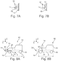
- the Figures 7A and 7B illustrate, respectively, in the active and broken positions, a bumper 74 adapted to replace the bumper 12. This is for example the bumper of the document EP1350680B1 .
- the bumper 74 is placed in front of the part 15 without leaving any space with this part 15. It is therefore contained in the zone 30 when it is in its active position.
- the Figures 8A and 8B represent a vehicle 90 identical to the vehicle 2 except that it comprises a bumper 92 in place of the bumper 12.
- the bumper 92 differs from the shock absorber 12 only in the way it is fixed to the vehicle 90.
- the bumper 92 in its retracted position, the bumper 92 is positioned not above the passenger compartment 10 but above the front end of the vehicle 2.
- the links 34 are placed on the chassis so that the orthogonal projection of the axis of rotation of the links 34 on the rolling plane lies between the respective orthogonal projections, on the same rolling plane, of the cockpit 10 and a transverse axis of the vehicle located just in front of the bumper 12 when in its active position.
- the face 14 is not flat but may instead have a convex or concave shape.
- the direction of the arms 20 is defined with respect to a frontal plane of the bumper 12.
- This frontal plane is defined as a vertical plane delimiting a base of the convex or concave shape of the face 14.
- the couplings 16 and 18 may be omitted. They can also be fixed on the chassis 4 with only one degree of freedom.
- the bumper 12 can be placed at the rear of the vehicle 2 so as to protect, when the bumper 12 is in the active position, a rear portion of the chassis, opposite to the part 15. In this case the bumper is configured to protect the rear hitch 18.
- the device 40 is modified accordingly.
- the vehicle 2 comprises two copies of the bumper 12 respectively configured to protect, in their respective active position, the front and rear portions of the frame 4.
- one of the arms 20 is omitted.
- the pivot connection 34 may have an axis of rotation different from the direction Y.
- Mechanism 45 may be different.
- the mechanism 45 comprises a curved shape of slide and along which the stopper 42 is able to move.
- the direction 43 is then not rectilinear.
- the links 34 may also be placed on the chassis so that the orthogonal projection of the axis of rotation of the links 34 on the rolling plane is between the respective orthogonal projections, on the same running plane, of the passenger compartment. 10 and a transverse axis of the vehicle located just behind the bumper 12 when in its active position.
- the pinions 46, 47 may be replaced by wheels connected together by a belt.
- the element 48 may be something other than a gas cylinder.
- the element 48 is a hydraulic cylinder associated with an oleopneumatic damper or a mechanical spring. Element 48 can also be omitted. In this case, the restoring force is exerted on the stopper 42, for example by the weight of the bumper 12.
- the vehicle 60 is not necessarily motorized.
- the bumper 62 is placed behind a rear end of the vehicle 60, so that its orthogonal projection in the rolling plane of the vehicle 60 is placed behind the orthogonal projection, in the same plane of the vehicle.
- the total length of the vehicle 60 is not reduced but additional protection is provided to the vehicle 60.
- the shock absorber can be made differently.
- the shock absorber is not necessarily a bumper.
- the shock absorber has a more limited protection function, such as the protection, in the active position, of a specific area of the vehicle 2.
- a more limited protection function such as the protection, in the active position, of a specific area of the vehicle 2.
- the vehicle 60 may have an opening in the front end of the chassis 4 in which the rear end of the chassis of the vehicle 2 is reversibly nested when these vehicles 2 and 60 are attached to form the convoy 50.
- the shock absorber is shaped so as to protect and cover this opening when in the active position.
- the shock absorber is for example a cover that covers this opening when it is in the active position.
- the definition of nested gear trains is for example that described in the application FR 1352128 supra.
- the vehicle 2 may comprise, in addition to the shock absorber, an additional bumper which is not able to move to a position retracted.
- This additional bumper is for example a bumper known in itself having the main function of protecting the vehicle 2 against mechanical shocks.
- the vehicle 2 may also not include this additional shock absorber and in this case it is the bumper 42 which has the function of absorbing mechanical shocks that can occur on the front end of the vehicle 2.
- the wheels 6, 8 can be placed differently on the frame 4.
- the wheels can extend, in the X direction, beyond the front and rear ends of the frame 4.
Landscapes
- Engineering & Computer Science (AREA)
- Mechanical Engineering (AREA)
- General Engineering & Computer Science (AREA)
- Chemical & Material Sciences (AREA)
- Combustion & Propulsion (AREA)
- Transportation (AREA)
- Body Structure For Vehicles (AREA)
Claims (10)
- Straßenkraftfahrzeug (2), umfassend:- ein Chassis (4), das sich entlang einer Längsachse zwischen einem vorderen Ende und einem hinteren Ende erstreckt;- einen Stoßdämpfer (12), der eine Vorderseite (14) umfasst und dazu geeignet ist, mindestens einen Teil der Energie eines mechanischen Stoßes gegen ein Hindernis, der auf seiner Vorderseite erhalten wird, zu absorbieren, indem er sich verformt:• ausgehend von einer aktiven Position, in der er direkt auf der Außenseite des Kraftfahrzeugs vor entweder dem vorderen oder dem hinteren Ende freiliegt, um dieses Ende vor einem mechanischen Stoß zu schützen,• zu einer Unfallsposition, die sich von der aktiven Position unterscheidet;- eine Verlagerungsvorrichtung (40), die dazu geeignet ist, automatisch abwechselnd und umkehrbar den Stoßdämpfer zu verlagern zwischen:• der aktiven Position und• einer eingefahrenen Position, die sich von der aktiven und der Unfallsposition unterscheidet,
dadurch gekennzeichnet, dass diese Verlagerungsvorrichtung (40) Folgendes umfasst:• einen beweglichen Anschlag (42), der dazu geeignet ist, auf einer Anlagefläche, die an einem anderen Fahrzeug befindet, zum Anliegen zu kommen, bevor der Stoßdämpfer dieses andere Fahrzeug berührt, wobei dieser Anschlag umkehrbar durch die Reaktionskraft der Anlagefläche, wenn sich das Fahrzeug (2) dem anderen Fahrzeug nähert, verlagerbar ist:∘ von einer ausgefahrenen Position,∘ zu einer eingefahrenen Position, in der der Anschlag weiter in das Innere des Fahrzeugs (2) eingesunken ist als in der ausgefahrenen Position;• eine mechanische Verbindung (45) zwischen dem Anschlag und dem Stoßdämpfer, wobei diese Verbindung dazu geeignet ist, die Verlagerung des Anschlags von seiner ausgefahrenen Position zu seiner eingefahrenen Position in eine entsprechende Verlagerung des Stoßdämpfers von seiner aktiven Position zu seiner eingefahrenen Position in dem Maße, in dem der Anschlag zu seiner eingefahrenen Position einsinkt, umzuwandeln. - Fahrzeug nach Anspruch 1, wobei die Verlagerungsvorrichtung (40) eine Zapfenverbindung (34) umfasst, um die der Stoßdämpfer dahingehend schwenken kann, sich zwischen seiner aktiven Position und seiner eingefahrenen Position zu verlagern, wenn er durch die Verlagerung des Anschlags (42) verlagert wird.
- Fahrzeug nach Anspruch 2, wobei sich der Anschlag nur in Verschiebung zwischen seiner ausgefahrenen und seiner eingefahrenen Position verlagert, und die mechanische Verbindung (45) Folgendes umfasst:- eine Zahnstange (44), die ohne Freiheitsgrad an dem Anschlag (42) befestigt ist, und- mindestens ein Ritzel (47), das dahingehend mit der Zahnstange (44) kämmt, die Verschiebung des Anschlags in eine Drehung dieses Zahnrads (46) umzuwandeln, wenn sich die Zahnstange (44) in Verschiebung und fest verbunden mit dem Stoßdämpfer verlagert, um diesen Stoßdämpfer zwischen seiner aktiven Position und seiner eingefahrenen Position in dem Maße, in dem sich Zapfen dreht, zu schwenken.
- Fahrzeug nach einem der vorhergehenden Ansprüche, wobei die Verlagerungsvorrichtung (40) ein Rückstellelement (48) umfasst, das den Anschlag durchweg zu seiner ausgefahrenen Position dahingehend belastet, den Stoßdämpfer (12) in seine aktive Position zurückzubringen wird, wenn sich dieses Fahrzeug von dem anderen Fahrzeug entfernt.
- Fahrzeug nach einem der vorhergehenden Ansprüche, wobei der Stoßdämpfer (12) ein Stoßfänger ist.
- Fahrzeug nach Anspruch 5, wobei:- das Fahrzeug einen Fahrgastraum (10) umfasst, der dazu geeignet ist, Insassen des Fahrzeugs unterzubringen, und- der Stoßfänger (12) in seiner eingefahrenen Position über dem Fahrgastraum liegt, so dass er einen Überrollbügel bildet, der dazu geeignet ist, das Zusammendrücken des Fahrgastraums im Fall eines Überschlags des Fahrzeugs einzuschränken.
- Fahrzeug nach Anspruch 6, wobei der Stoßfänger eine Bogenform aufweist und dazu Arme (20) umfasst, die an jedem Ende der Vorderseite liegen und sich senkrecht ± 30 % zu dieser Vorderseite auf auf jeder Seite des Fahrzeugs erstrecken, wobei diese Arme jeweils Seitenflächen aufweisen, die direkt auf der Außenseite des Fahrzeugs freiliegen, um einen mechanischen Stoß zu absorbieren, der auf einer Seitenflanke des Fahrzeugs auftreten kann, wenn der Stoßfänger in seiner aktiven Position ist.
- Fahrzeug nach den Ansprüchen 2 und 7, wobei sich die Verbindungszapfen (34) auf jeder Seite des Fahrzeugs befinden und freie Enden der Arme (20) mechanisch mit dem Chassis verbinden, wobei diese Zapfenverbindungen es erlauben, den Stoßfänger durch Drehung um Drehachsen (Y) der Zapfenverbindungen zwischen seiner eingefahrenen und seiner aktiven Position zu verlagern.
- Fahrzeug nach einem der vorhergehenden Ansprüche, wobei das Fahrzeug eine vordere (16) und eine hintere (18) Koppelvorrichtung umfasst, die sich an dem vorderen bzw. dem hinteren Ende des Chassis befinden, um dieses Fahrzeug mit anderen koppelbaren Straßenkraftfahrzeugen zu koppeln, um einen Straßenlastzug (50) zu bilden,» wobei die vordere Kopplung abwechselnd verlagerbar ist zwischen:∘ einer gekoppelten Position, in der diese vordere Kopplung mit einer hinteren Kopplung, die mit der hinteren Kopplung dieses Fahrzeugs identisch ist und sich auf einem anderen Fahrzeug befindet, dahingehend zusammenwirkt, diese Fahrzeuge mechanisch aneinander zu befestigen, und∘ eine abgekoppelte Position, in der diese Fahrzeuge voneinander getrennt sind;» wobei die hintere Kopplung abwechselnd verlagerbar ist zwischen:∘ einer gekoppelten Position, in der diese hintere Kopplung mit einer vorderen Kopplung, die mit der vorderen Kopplung dieses Fahrzeugs identisch ist und sich auf einem anderen Fahrzeug befindet, dahingehend zusammenwirkt, diese Fahrzeuge mechanisch aneinander zu befestigen, und∘ einer abgekoppelten Position, in der diese Fahrzeuge voneinander getrennt sind.
- Fahrzeug nach Anspruch 9, wobei der Stoßdämpfer (12) in der aktiven Position vor entweder der vorderen oder hinteren Kopplung des Fahrzeugs platziert ist, um diese Kopplung vor einem mechanischen Stoß zu schützen.
Applications Claiming Priority (2)
| Application Number | Priority Date | Filing Date | Title |
|---|---|---|---|
| FR1451571A FR3002898B1 (fr) | 2013-03-08 | 2014-02-27 | Vehicule automobile routier comportant un amortisseur de chocs escamotable |
| PCT/FR2015/050454 WO2015128583A1 (fr) | 2014-02-27 | 2015-02-26 | Vehicule automobile routier comportant un amortisseur de chocs escamotable |
Publications (2)
| Publication Number | Publication Date |
|---|---|
| EP3110665A1 EP3110665A1 (de) | 2017-01-04 |
| EP3110665B1 true EP3110665B1 (de) | 2018-03-14 |
Family
ID=52815010
Family Applications (1)
| Application Number | Title | Priority Date | Filing Date |
|---|---|---|---|
| EP15714856.0A Active EP3110665B1 (de) | 2014-02-27 | 2015-02-26 | Kraftfahrzeug mit einklappbarem stossdämpfer |
Country Status (3)
| Country | Link |
|---|---|
| EP (1) | EP3110665B1 (de) |
| KR (1) | KR20160125423A (de) |
| WO (1) | WO2015128583A1 (de) |
Family Cites Families (4)
| Publication number | Priority date | Publication date | Assignee | Title |
|---|---|---|---|---|
| FR1352128A (fr) | 1962-09-03 | 1964-02-14 | Foreuse universelle à vibro-rotation et percussion à carottage intégral | |
| US5417300A (en) | 1991-06-27 | 1995-05-23 | Shultz; Richard E. | Compact stackable vehicle |
| FR2696391B1 (fr) | 1992-10-02 | 1994-12-09 | France Design | Véhicule de longueur modifiable. |
| FR2836878B1 (fr) | 2002-03-08 | 2004-07-09 | Plastic Omnium Cie | Absorbeur d'energie destine a s'intercaler entre une poutre rigide et une peau de pare-chocs et ensemble d'absorption d'energie |
-
2015
- 2015-02-26 WO PCT/FR2015/050454 patent/WO2015128583A1/fr not_active Ceased
- 2015-02-26 KR KR1020167025564A patent/KR20160125423A/ko not_active Ceased
- 2015-02-26 EP EP15714856.0A patent/EP3110665B1/de active Active
Also Published As
| Publication number | Publication date |
|---|---|
| KR20160125423A (ko) | 2016-10-31 |
| WO2015128583A1 (fr) | 2015-09-03 |
| EP3110665A1 (de) | 2017-01-04 |
Similar Documents
| Publication | Publication Date | Title |
|---|---|---|
| FR3002898A1 (fr) | Vehicule automobile routier comportant un amortisseur de chocs escamotable | |
| EP2485935B1 (de) | Stossdämpfende vorrichtung für ein unter dem fahrzeugrahmen montiertes kraftfahrzeugelement | |
| EP2186686B1 (de) | Verschiebungsvorrichtung eines starren Elements und mit einer solchen Vorrichtung ausgestattetes Fahrzeug | |
| FR2899530A1 (fr) | Appui-tete pour sieges de vehicule automobile | |
| EP3691959A1 (de) | Koppelbares automotives strassenfahrzeug mit kompakter lenkung und aufhängung | |
| EP2022682B1 (de) | Karosseriestruktur eines Kraftfahrzeugs und eine solche Karosseriestruktur umfassendes Kraftfahrzeug | |
| EP3615385B1 (de) | Gelenkige detektions- oder kommunikationsvorrichtung und zugehöriges fahrzeug | |
| EP1827943B1 (de) | Stossdämpfungsvorrichtung für eisenbahnfahrzeug | |
| FR2943597A1 (fr) | Ensemble de pare-chocs pour un vehicule automobile | |
| EP3110665B1 (de) | Kraftfahrzeug mit einklappbarem stossdämpfer | |
| EP2969705B1 (de) | Kraftfahrzeug mit mittel zur positionierung einer zusammenschiebbaren lenksäule | |
| FR3048954A1 (fr) | Systeme de desengagement verrouillable d’actionneur de roue sur un atterisseur d’aeronef. | |
| FR2948914A1 (fr) | Traverse de planche de bord et vehicule equipe d'une telle traverse | |
| FR2944240A1 (fr) | Partie arriere d'un vehicule equipe d'un volet inferieur apte a absorber un choc | |
| WO2010081949A1 (fr) | Support de charnon mobile amortisseur de choc pieton | |
| EP1780102B1 (de) | Vorderbau für ein Kraftfahrzeug mit einer Einrichtung zum Schutz gegen das Eindringen eines Rades in die Fahrgastzelle bei einem Frontalaufprall | |
| FR3045535A1 (fr) | Agencement d’une cloison de separation modulable a l’interieur d’un vehicule automobile | |
| EP1594731A1 (de) | Fahrzeug, insbesondere schienenfahrzeug, mit rückziehbarer kupplung | |
| EP2857260B1 (de) | Sitz für Militärfahrzeug | |
| EP1916134A1 (de) | Kraftfahrzeug-Heckklappe | |
| EP2130717A1 (de) | System zur Begrenzung von Schäden im Fall von Aufprall, die von einem Sichtelement oder zumindest einem Organ eines Kraftfahrzeugs erzeugt werden könnten | |
| FR2997673A1 (fr) | Cadre support pour groupe electro-propulseur pourvu d'organes de repartition d'effort de choc | |
| EP3215377B1 (de) | Nabenträger für eine verbundlenkerachse | |
| EP2727762B1 (de) | Formveränderbare Gondel für Fahrzeug | |
| EP1361119A1 (de) | Passive Schutzvorrichtung und Fahrzeug mit einer solchen Vorrichtung |
Legal Events
| Date | Code | Title | Description |
|---|---|---|---|
| PUAI | Public reference made under article 153(3) epc to a published international application that has entered the european phase |
Free format text: ORIGINAL CODE: 0009012 |
|
| STAA | Information on the status of an ep patent application or granted ep patent |
Free format text: STATUS: REQUEST FOR EXAMINATION WAS MADE |
|
| 17P | Request for examination filed |
Effective date: 20160811 |
|
| AK | Designated contracting states |
Kind code of ref document: A1 Designated state(s): AL AT BE BG CH CY CZ DE DK EE ES FI FR GB GR HR HU IE IS IT LI LT LU LV MC MK MT NL NO PL PT RO RS SE SI SK SM TR |
|
| AX | Request for extension of the european patent |
Extension state: BA ME |
|
| DAX | Request for extension of the european patent (deleted) | ||
| GRAP | Despatch of communication of intention to grant a patent |
Free format text: ORIGINAL CODE: EPIDOSNIGR1 |
|
| STAA | Information on the status of an ep patent application or granted ep patent |
Free format text: STATUS: GRANT OF PATENT IS INTENDED |
|
| INTG | Intention to grant announced |
Effective date: 20171005 |
|
| GRAS | Grant fee paid |
Free format text: ORIGINAL CODE: EPIDOSNIGR3 |
|
| GRAA | (expected) grant |
Free format text: ORIGINAL CODE: 0009210 |
|
| STAA | Information on the status of an ep patent application or granted ep patent |
Free format text: STATUS: THE PATENT HAS BEEN GRANTED |
|
| AK | Designated contracting states |
Kind code of ref document: B1 Designated state(s): AL AT BE BG CH CY CZ DE DK EE ES FI FR GB GR HR HU IE IS IT LI LT LU LV MC MK MT NL NO PL PT RO RS SE SI SK SM TR |
|
| REG | Reference to a national code |
Ref country code: GB Ref legal event code: FG4D Free format text: NOT ENGLISH |
|
| REG | Reference to a national code |
Ref country code: CH Ref legal event code: EP Ref country code: AT Ref legal event code: REF Ref document number: 978543 Country of ref document: AT Kind code of ref document: T Effective date: 20180315 |
|
| REG | Reference to a national code |
Ref country code: IE Ref legal event code: FG4D Free format text: LANGUAGE OF EP DOCUMENT: FRENCH |
|
| REG | Reference to a national code |
Ref country code: DE Ref legal event code: R096 Ref document number: 602015008834 Country of ref document: DE |
|
| REG | Reference to a national code |
Ref country code: ES Ref legal event code: FG2A Ref document number: 2670432 Country of ref document: ES Kind code of ref document: T3 Effective date: 20180530 |
|
| REG | Reference to a national code |
Ref country code: NL Ref legal event code: MP Effective date: 20180314 |
|
| REG | Reference to a national code |
Ref country code: LT Ref legal event code: MG4D |
|
| PG25 | Lapsed in a contracting state [announced via postgrant information from national office to epo] |
Ref country code: CY Free format text: LAPSE BECAUSE OF FAILURE TO SUBMIT A TRANSLATION OF THE DESCRIPTION OR TO PAY THE FEE WITHIN THE PRESCRIBED TIME-LIMIT Effective date: 20180314 Ref country code: FI Free format text: LAPSE BECAUSE OF FAILURE TO SUBMIT A TRANSLATION OF THE DESCRIPTION OR TO PAY THE FEE WITHIN THE PRESCRIBED TIME-LIMIT Effective date: 20180314 Ref country code: NO Free format text: LAPSE BECAUSE OF FAILURE TO SUBMIT A TRANSLATION OF THE DESCRIPTION OR TO PAY THE FEE WITHIN THE PRESCRIBED TIME-LIMIT Effective date: 20180614 Ref country code: LT Free format text: LAPSE BECAUSE OF FAILURE TO SUBMIT A TRANSLATION OF THE DESCRIPTION OR TO PAY THE FEE WITHIN THE PRESCRIBED TIME-LIMIT Effective date: 20180314 Ref country code: HR Free format text: LAPSE BECAUSE OF FAILURE TO SUBMIT A TRANSLATION OF THE DESCRIPTION OR TO PAY THE FEE WITHIN THE PRESCRIBED TIME-LIMIT Effective date: 20180314 |
|
| REG | Reference to a national code |
Ref country code: AT Ref legal event code: MK05 Ref document number: 978543 Country of ref document: AT Kind code of ref document: T Effective date: 20180314 |
|
| PG25 | Lapsed in a contracting state [announced via postgrant information from national office to epo] |
Ref country code: SE Free format text: LAPSE BECAUSE OF FAILURE TO SUBMIT A TRANSLATION OF THE DESCRIPTION OR TO PAY THE FEE WITHIN THE PRESCRIBED TIME-LIMIT Effective date: 20180314 Ref country code: LV Free format text: LAPSE BECAUSE OF FAILURE TO SUBMIT A TRANSLATION OF THE DESCRIPTION OR TO PAY THE FEE WITHIN THE PRESCRIBED TIME-LIMIT Effective date: 20180314 Ref country code: RS Free format text: LAPSE BECAUSE OF FAILURE TO SUBMIT A TRANSLATION OF THE DESCRIPTION OR TO PAY THE FEE WITHIN THE PRESCRIBED TIME-LIMIT Effective date: 20180314 Ref country code: BG Free format text: LAPSE BECAUSE OF FAILURE TO SUBMIT A TRANSLATION OF THE DESCRIPTION OR TO PAY THE FEE WITHIN THE PRESCRIBED TIME-LIMIT Effective date: 20180614 Ref country code: GR Free format text: LAPSE BECAUSE OF FAILURE TO SUBMIT A TRANSLATION OF THE DESCRIPTION OR TO PAY THE FEE WITHIN THE PRESCRIBED TIME-LIMIT Effective date: 20180615 |
|
| PG25 | Lapsed in a contracting state [announced via postgrant information from national office to epo] |
Ref country code: MT Free format text: LAPSE BECAUSE OF FAILURE TO SUBMIT A TRANSLATION OF THE DESCRIPTION OR TO PAY THE FEE WITHIN THE PRESCRIBED TIME-LIMIT Effective date: 20180314 |
|
| PG25 | Lapsed in a contracting state [announced via postgrant information from national office to epo] |
Ref country code: RO Free format text: LAPSE BECAUSE OF FAILURE TO SUBMIT A TRANSLATION OF THE DESCRIPTION OR TO PAY THE FEE WITHIN THE PRESCRIBED TIME-LIMIT Effective date: 20180314 Ref country code: NL Free format text: LAPSE BECAUSE OF FAILURE TO SUBMIT A TRANSLATION OF THE DESCRIPTION OR TO PAY THE FEE WITHIN THE PRESCRIBED TIME-LIMIT Effective date: 20180314 Ref country code: EE Free format text: LAPSE BECAUSE OF FAILURE TO SUBMIT A TRANSLATION OF THE DESCRIPTION OR TO PAY THE FEE WITHIN THE PRESCRIBED TIME-LIMIT Effective date: 20180314 Ref country code: PL Free format text: LAPSE BECAUSE OF FAILURE TO SUBMIT A TRANSLATION OF THE DESCRIPTION OR TO PAY THE FEE WITHIN THE PRESCRIBED TIME-LIMIT Effective date: 20180314 Ref country code: AL Free format text: LAPSE BECAUSE OF FAILURE TO SUBMIT A TRANSLATION OF THE DESCRIPTION OR TO PAY THE FEE WITHIN THE PRESCRIBED TIME-LIMIT Effective date: 20180314 |
|
| PG25 | Lapsed in a contracting state [announced via postgrant information from national office to epo] |
Ref country code: AT Free format text: LAPSE BECAUSE OF FAILURE TO SUBMIT A TRANSLATION OF THE DESCRIPTION OR TO PAY THE FEE WITHIN THE PRESCRIBED TIME-LIMIT Effective date: 20180314 Ref country code: SM Free format text: LAPSE BECAUSE OF FAILURE TO SUBMIT A TRANSLATION OF THE DESCRIPTION OR TO PAY THE FEE WITHIN THE PRESCRIBED TIME-LIMIT Effective date: 20180314 Ref country code: SK Free format text: LAPSE BECAUSE OF FAILURE TO SUBMIT A TRANSLATION OF THE DESCRIPTION OR TO PAY THE FEE WITHIN THE PRESCRIBED TIME-LIMIT Effective date: 20180314 Ref country code: CZ Free format text: LAPSE BECAUSE OF FAILURE TO SUBMIT A TRANSLATION OF THE DESCRIPTION OR TO PAY THE FEE WITHIN THE PRESCRIBED TIME-LIMIT Effective date: 20180314 |
|
| REG | Reference to a national code |
Ref country code: DE Ref legal event code: R097 Ref document number: 602015008834 Country of ref document: DE |
|
| PG25 | Lapsed in a contracting state [announced via postgrant information from national office to epo] |
Ref country code: PT Free format text: LAPSE BECAUSE OF FAILURE TO SUBMIT A TRANSLATION OF THE DESCRIPTION OR TO PAY THE FEE WITHIN THE PRESCRIBED TIME-LIMIT Effective date: 20180716 |
|
| PLBE | No opposition filed within time limit |
Free format text: ORIGINAL CODE: 0009261 |
|
| STAA | Information on the status of an ep patent application or granted ep patent |
Free format text: STATUS: NO OPPOSITION FILED WITHIN TIME LIMIT |
|
| PG25 | Lapsed in a contracting state [announced via postgrant information from national office to epo] |
Ref country code: DK Free format text: LAPSE BECAUSE OF FAILURE TO SUBMIT A TRANSLATION OF THE DESCRIPTION OR TO PAY THE FEE WITHIN THE PRESCRIBED TIME-LIMIT Effective date: 20180314 |
|
| 26N | No opposition filed |
Effective date: 20181217 |
|
| PG25 | Lapsed in a contracting state [announced via postgrant information from national office to epo] |
Ref country code: SI Free format text: LAPSE BECAUSE OF FAILURE TO SUBMIT A TRANSLATION OF THE DESCRIPTION OR TO PAY THE FEE WITHIN THE PRESCRIBED TIME-LIMIT Effective date: 20180314 |
|
| REG | Reference to a national code |
Ref country code: CH Ref legal event code: PL |
|
| PG25 | Lapsed in a contracting state [announced via postgrant information from national office to epo] |
Ref country code: LU Free format text: LAPSE BECAUSE OF NON-PAYMENT OF DUE FEES Effective date: 20190226 Ref country code: MC Free format text: LAPSE BECAUSE OF FAILURE TO SUBMIT A TRANSLATION OF THE DESCRIPTION OR TO PAY THE FEE WITHIN THE PRESCRIBED TIME-LIMIT Effective date: 20180314 |
|
| REG | Reference to a national code |
Ref country code: BE Ref legal event code: MM Effective date: 20190228 |
|
| REG | Reference to a national code |
Ref country code: IE Ref legal event code: MM4A |
|
| PG25 | Lapsed in a contracting state [announced via postgrant information from national office to epo] |
Ref country code: LI Free format text: LAPSE BECAUSE OF NON-PAYMENT OF DUE FEES Effective date: 20190228 Ref country code: CH Free format text: LAPSE BECAUSE OF NON-PAYMENT OF DUE FEES Effective date: 20190228 |
|
| PG25 | Lapsed in a contracting state [announced via postgrant information from national office to epo] |
Ref country code: IE Free format text: LAPSE BECAUSE OF NON-PAYMENT OF DUE FEES Effective date: 20190226 |
|
| PG25 | Lapsed in a contracting state [announced via postgrant information from national office to epo] |
Ref country code: BE Free format text: LAPSE BECAUSE OF NON-PAYMENT OF DUE FEES Effective date: 20190228 |
|
| PG25 | Lapsed in a contracting state [announced via postgrant information from national office to epo] |
Ref country code: TR Free format text: LAPSE BECAUSE OF FAILURE TO SUBMIT A TRANSLATION OF THE DESCRIPTION OR TO PAY THE FEE WITHIN THE PRESCRIBED TIME-LIMIT Effective date: 20180314 |
|
| PG25 | Lapsed in a contracting state [announced via postgrant information from national office to epo] |
Ref country code: IS Free format text: LAPSE BECAUSE OF FAILURE TO SUBMIT A TRANSLATION OF THE DESCRIPTION OR TO PAY THE FEE WITHIN THE PRESCRIBED TIME-LIMIT Effective date: 20180714 |
|
| PG25 | Lapsed in a contracting state [announced via postgrant information from national office to epo] |
Ref country code: HU Free format text: LAPSE BECAUSE OF FAILURE TO SUBMIT A TRANSLATION OF THE DESCRIPTION OR TO PAY THE FEE WITHIN THE PRESCRIBED TIME-LIMIT; INVALID AB INITIO Effective date: 20150226 |
|
| PG25 | Lapsed in a contracting state [announced via postgrant information from national office to epo] |
Ref country code: MK Free format text: LAPSE BECAUSE OF FAILURE TO SUBMIT A TRANSLATION OF THE DESCRIPTION OR TO PAY THE FEE WITHIN THE PRESCRIBED TIME-LIMIT Effective date: 20180314 |
|
| PGFP | Annual fee paid to national office [announced via postgrant information from national office to epo] |
Ref country code: DE Payment date: 20250218 Year of fee payment: 11 |
|
| PGFP | Annual fee paid to national office [announced via postgrant information from national office to epo] |
Ref country code: ES Payment date: 20250318 Year of fee payment: 11 |
|
| PGFP | Annual fee paid to national office [announced via postgrant information from national office to epo] |
Ref country code: FR Payment date: 20250219 Year of fee payment: 11 |
|
| PGFP | Annual fee paid to national office [announced via postgrant information from national office to epo] |
Ref country code: IT Payment date: 20250228 Year of fee payment: 11 Ref country code: GB Payment date: 20250218 Year of fee payment: 11 |