EP3111155B1 - Dispositif de réglage de portée - Google Patents
Dispositif de réglage de portée Download PDFInfo
- Publication number
- EP3111155B1 EP3111155B1 EP15755342.1A EP15755342A EP3111155B1 EP 3111155 B1 EP3111155 B1 EP 3111155B1 EP 15755342 A EP15755342 A EP 15755342A EP 3111155 B1 EP3111155 B1 EP 3111155B1
- Authority
- EP
- European Patent Office
- Prior art keywords
- marker
- riflescope
- processor
- ocular
- image
- Prior art date
- Legal status (The legal status is an assumption and is not a legal conclusion. Google has not performed a legal analysis and makes no representation as to the accuracy of the status listed.)
- Not-in-force
Links
- 239000003550 marker Substances 0.000 claims description 49
- 230000003287 optical effect Effects 0.000 claims description 17
- 238000000034 method Methods 0.000 claims description 15
- 230000008569 process Effects 0.000 claims description 5
- 230000003213 activating effect Effects 0.000 claims description 4
- 239000012190 activator Substances 0.000 claims description 2
- 210000004209 hair Anatomy 0.000 description 10
- 230000006870 function Effects 0.000 description 6
- 230000008901 benefit Effects 0.000 description 4
- 230000007246 mechanism Effects 0.000 description 4
- 238000004891 communication Methods 0.000 description 3
- 238000010276 construction Methods 0.000 description 3
- 238000005286 illumination Methods 0.000 description 3
- 239000000463 material Substances 0.000 description 3
- 230000004297 night vision Effects 0.000 description 3
- 230000008859 change Effects 0.000 description 2
- 230000000295 complement effect Effects 0.000 description 2
- 230000007547 defect Effects 0.000 description 2
- 230000000694 effects Effects 0.000 description 2
- 230000035939 shock Effects 0.000 description 2
- 238000001228 spectrum Methods 0.000 description 2
- 230000001629 suppression Effects 0.000 description 2
- 230000000007 visual effect Effects 0.000 description 2
- 239000005084 Strontium aluminate Substances 0.000 description 1
- YZCKVEUIGOORGS-NJFSPNSNSA-N Tritium Chemical compound [3H] YZCKVEUIGOORGS-NJFSPNSNSA-N 0.000 description 1
- 230000004913 activation Effects 0.000 description 1
- 230000002860 competitive effect Effects 0.000 description 1
- 235000012489 doughnuts Nutrition 0.000 description 1
- 230000005611 electricity Effects 0.000 description 1
- 238000003384 imaging method Methods 0.000 description 1
- 230000000717 retained effect Effects 0.000 description 1
- 230000006641 stabilisation Effects 0.000 description 1
- FNWBQFMGIFLWII-UHFFFAOYSA-N strontium aluminate Chemical compound [O-2].[O-2].[O-2].[O-2].[O-2].[Al+3].[Al+3].[Sr+2].[Sr+2] FNWBQFMGIFLWII-UHFFFAOYSA-N 0.000 description 1
- 239000000126 substance Substances 0.000 description 1
- 230000008685 targeting Effects 0.000 description 1
- 229910052722 tritium Inorganic materials 0.000 description 1
Images






Classifications
-
- F—MECHANICAL ENGINEERING; LIGHTING; HEATING; WEAPONS; BLASTING
- F41—WEAPONS
- F41G—WEAPON SIGHTS; AIMING
- F41G1/00—Sighting devices
- F41G1/38—Telescopic sights specially adapted for smallarms or ordnance; Supports or mountings therefor
Definitions
- the present invention relates to attachments for scopes and in particular, though not exclusively, for firearm scopes.
- Telescopic sights such as riflescopes are used in any light conditions from bright daylight through lowest light conditions including night time uses.
- the user In order to view or aim in lowest light conditions the user typically connects additional analogue or digital Night-Vision instruments either to the objective or to the ocular of the telescopic sight.
- the user has to choose a specific optical power setting (fixed power) or a specific zoom range (variable power scope) thus limiting the application range of the telescopic sight overall.
- the user has to select one specific aiming mark which cannot be adapted to the situation. The aiming mark can only be set to one specific zero-setting with no adaptability for different shooting distances, wind conditions, inclination, canting and other external factors effecting shooting precision in the field.
- US2012000979A1 discloses a riflescope that includes a processor and a brightness sensor in communication with the processor.
- the riflescope includes a display in communication with the processor that displays a corrected aiming point based on a simulated bullet trajectory and a simulated bullet impact location determined by the processor.
- the brightness sensor is used to automatically adjust the illumination supplied to the reticle pattern of the riflescope.
- a riflescope comprising a main housing, an objective group, a first reticle comprising at least one physical reticle mark and a detachable digital ocular group.
- the objective group includes at least one objective lens disposed toward an objective end of the main housing.
- the detachable digital ocular group includes a second housing attachable to and detachable from an ocular end of the main housing, an image(photo) -sensor, at least one processor and a digital display.
- the image(photo) sensor is configured to receive light that has entered the objective end of the main housing and the processor is programmed to process the light received by the image(photo) sensor and to display an image representative of the received light on the digital display.
- the detachable digital ocular group may be replaceable with an unpowered ocular group comprising a third housing attachable to and detachable from an ocular end of the main housing and one or more second ocular optical elements disposed within the third housing.
- the first reticle comprises one or more marker materials that are not visible to an operator of the riflescope during normal use of the riflescope.
- a method for calibrating a riflescope comprising a reticle, an image(photo) at least one processor and a digital display.
- the method comprises receiving light from a marker at an image plane of the reticle into the photosensor.
- the processor processes the received light to detect a location of the marker.
- the processor calibrates the digital display from the detected location of the marker.
- the present innovation shows a way of how to convert a conventional riflescope into a full day- and night riflescope by means of interchangeable eye pieces (optical and digital). Also it is presented how to change a fixed optical power setting and a given optical zoom range by means of a digital zoom function. Also it is presented how to support the user in adapting to different shooting distances, wind conditions inclination, canting and other factors by means of a secondary aiming mark which is superimposed over the optical image. Also the present riflescope concept allows for use without power (optical eye piece) or in case of electronics defect or weak batteries (with optical eye piece only).
- a riflescope 10 includes a housing comprising a main housing 12 having an objective end 13 and an ocular end 14.
- a second housing 16 is attachable to and detachable from the main housing at the ocular end 14.
- the second housing 16 may attach/detach from the main housing 12 through various attachment mechanisms including, with limitation, complementary screw threads 18, 19, bayonet fittings, clips or other suitable connection mechanisms that may or may not require the use of tools etc.
- an objective group comprising one or more objective lens elements that direct light 23 entering the housing through the objective end 13 toward a first image plane 24.
- a reticle 26 may be disposed in or near the first image plane 24.
- the reticle 26 may include one or more reticle marks as will be described in greater detail below.
- the placement of the reticle 26 may be adjustable through one or more adjustment mechanisms 29, as is known in the art.
- the main housing 12 also houses an erector group 28 which may include one or more erector elements such as, without limitation, an erector prism.
- Figure 1 shows the ocular group housing 16 detached from the main housing 12 while Figure 2 shows the ocular group housing 16 attached to the main housing 12 with engagement between the complementary screw threads 18, 19.
- the ocular group housing 16 houses one or more ocular optical elements 17 in a non-powered arrangement, thus providing an ocular group 22.
- the specific elements of the non-powered ocular group 22 may be regarded as conventional and thus no further description of the non-powered ocular group is considered necessary herein.
- the non-powered ocular group 22 may be adapted to the scope for use under primarily daytime or well-lit conditions or for use with other night-time accessories.
- FIG. 3 shows the non-powered ocular group 22 replaced by a powered ocular group 30 in accordance with one embodiment of the present invention.
- the components of the powered ocular group 30 are disposed within a housing 38 that is attachable to and detachable from the main housing 12 in the same manner as for the non-powered ocular housing 16 described above.
- the powered ocular group 30 includes, with respect to the direction of light travel 23 through the riflescope, a photo sensor board 31 comprising one or more photosensors disposed at a second image plane 37, a digital display 33 and one or more optical elements 35 that magnify the image of the display 33 for projection to the user through the ocular end of the housing 38.
- the powered ocular group also includes an electronics group 34 including at least one processor, a memory for storing a program or instructions executable by the at least one processor, and associated circuitry.
- the photo sensor 31 may include a CCD, CMOS-sensor (or similar) and is configured to receive light that has entered the riflescope from the objective end 13 of the main housing 12 and passed through the objective 20 and erector groups 28.
- the electronics group 34 is programmed to process the light received by the photo sensor 31 and to display an image representative of the received light on the digital display 33.
- the representative image displayed on the digital display 33 does not necessarily need to be an exact reproduction of the image received at the photo sensor 31 but instead may include one or more enhancements, such as, without limitation, night vision enhancements, magnification, suppression or enhancement of specific aspects or areas of the image, digital overlays (e.g. of targeting marks), etc..
- the digital display 33 may include a very low threshold (display) to avoid blinding user's eye in lowest light conditions.
- a control panel may be provided on an external surface of the powered ocular housing 38 to enable a user to input control commands to the electronics group 34.
- Example control commands include, without limitation, display commands, calibration commands, preference settings, etc.
- Specific operations may include, without limitation ON/OFF selection, display brightness control, electronic aiming mark selection, remote control for an external device such as handlamps or infra-red illuminators and other functions
- One or more additional optical elements may be placed in front of the photo sensor 31, with respect to the direction of light travel through the riflescope, if required to achieve the imaging functions of the riflescope.
- FIG. 4 An example view through the riflescope from the ocular end is shown in Figure 4 .
- the view of Figure 4 shows the reticle featuring conventional cross hair marks 40 including horizontal 41 and vertical lines 42. Other reticle marks will be apparent to a person skilled in the art.
- the lines 41, 42 are visible to the user during normal use of the riflescope using either the conventional ocular group 20 or the powered ocular group 30.
- the electronics group may be configured to digitally overlay one or more secondary aiming marks at the second image plane 37, i.e. in the plane of the photosensors.
- Figure 5 shows a representation through the ocular in which the cross hair 40 in the first image plane has been overlaid with a circle aiming mark 51 in the second image plane.
- Figure 6 shows a first alternative in which lead marks 53 are digitally laid over the 1 st image plane reticle while Figure 7 shows digitally overlaid ballistic holdover lines.
- Figure 8 depicts an example in which the processing software of the electronics group 34 digitally suppresses the image of the first image plane cross hairs 40 on the digital display 33.
- the digital ocular group delivers more than one aiming mark type such as circles, donuts, small crosses, posts, cones, arrows, dots or similar.
- the digital ocular delivers secondary aiming marks to correct for bullet drop, inclination, altitude, temperature, humidity, geo-position (all: hold-over lines), cross wind (wind marks) or moving game aiming point error (lead marks).
- the digital ocular delivers the above information as data displayed on the micro display.
- a detachable digital ocular that can be replaced by a conventional ocular group ensures that the riflescope remains functional in the event of a power or electronics failure of the digital ocular.
- the detachability of the digital ocular can introduce new sources of error and inaccuracy due to potential misalignment of the digital ocular housing 38 with the main riflescope housing 12.
- Any high quality riflescope should aim to deliver a total opto-mechanical tolerance of 1 MoA (minute of angle) during regular use of the product, which includes zooming, usual temperature changes, zeroing-in and shooting with g-forces around 1,000g within a 1 to 2 ms peak time.
- the mechanical interface between the main housing 12 and the ocular housing 38 can cause substantially more movement of the ocular-eye piece when in use than with a conventional one-piece riflescope housing.
- the additional tolerance deviation may be kept fairly low, but would force the product into additional mass that would make the product too heavy for a competitive riflescope.
- the described detachable ocular tolerance dilemma occurs mainly through shooting (shock), through handling the eye piece (e.g. lifting the rifle-optics set by the ocular and the resulting leverage effect hereof), through changing the eye piece (repetition error), through temperature changes (expansion) but also through other forces that effect the alignment of the ocular against the objective-erector system unit (riflescope 'body').
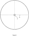
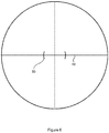
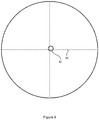
- a marker 45 may be provided in the first image plane reticle 26, as shown in Figure 10 .
- the marker 45 may be visible or detectable by the photosensor board 31 but is not visible to the human eye or within the light spectrum range of night vision devices such as the powered ocular group 30. That is, the marker 45 is not visible to the user during general operation or use of the riflescope.
- the marker 45 is a cross shape in the center of the visible cross hair 40.
- the marker 45 may comprise four disc shaped markers 48 at the edges of the cross hair wires.
- the marker 45 may be provided at various positions and in various forms on the first reticule 26. Alternatively more than one marker may be used. Alternatively the whole reticle surface acts as a marker surface.
- the marker material 45 may be a passive marker, i.e. non-battery activated, such as tritium, strontium-aluminate or other luminescent substance.
- the marker 45 may be an active marker that is activated by electricity, light rays or other activators.
- the crosshair center should be identified by a sensor-software package by an illumination that does not distract the eye in any light condition, and especially not at low light when the iris is wide open. So the illumination (active or passive) is ideally not within the 400 to 700 Nanometer-Spectrum that the human eye is able to see.
- Figure 3 shows the provision of a light infra-red (IR) emitting diode 39 inside the powered ocular housing 38.
- the diode 39 emits IR light (or alternatively UV light) toward the first image plane in order to activate the marker 45 to make the marker 45 detectable by the photosensors 31.
- IR light infra-red
- the riflescope is zeroed in through the mechanical reticle like any conventional riflescope, thus locating the cross hair center (or similar aiming mark) in the correct position towards the desired basic zeroing distance.
- a calibration procedure may commence by activating the marker, such as by switching the IR diode 39 on to cause IR light to be emitted towards the 1st image plane reticle 26, thus activating the marker 45.
- the sensor 31 detects the light reflected by the IR-lighted reticle marker 45, or otherwise detects the passive marker and a detection software defines the location of the marker in a grid corresponding to the first image plane.
- Calibration software then shifts the digital display until the digitally overlaid aiming marks of the second image plane aligns with the detected marker 45.
- the detection-calibration process may be repeated either manually by commands through the control panel, or may be performed automatically, such as periodically after a defined time laps (e.g. every 15 seconds), after every round fired (e.g. accelerometer chip), after mounting the digital eye piece, or when using the click mechanism (e.g. click movement sensor).
- a defined time laps e.g. every 15 seconds
- a round fired e.g. accelerometer chip
- the click mechanism e.g. click movement sensor
- the use of the IR marker overcomes the problem that in daylight it is difficult for software to detect the crosshair (or any physical reference points) in the 1st image plane against the ever changing background (target image). In lowest light conditions this becomes nearly impossible.
- the use of the IR marker and LED allows the first image plane reticle / reference points to be illuminated in a way that is more easily found by the software but that is not visible to the human eye (to avoid distraction by light impulses or blinding).
- an ultra-violet (UV) marker may be used in place of an IR marker.
- the secondary superimposed aiming mark may be manually or automatically adjusted to a visual holdover position according to ballistic functions and or to a visual lead position according to the prevailing wind conditions, canting of the telescope or other alignment relevant external factors.
- the digital ocular may include a digital zoom function in order to increase the optical magnification performance.
- Software for providing digital zoom is well known in the art.
- the digital ocular may incorporate known image stabilization software and known software for image capturing.
- the digital ocular may include digital motion detector that silently alarms the user when movement is detected by a special software. e.g. through a smartphone in VibraCall-mode (Bluetooth).
- VibraCall-mode Bluetooth
- the digital ocular may include one or more ports or sockets for communication with external devices, socket for charging (e.g. USB), Bluetooth connectivity, etc.
- socket for charging e.g. USB
- Bluetooth connectivity e.g.
- the ocular group may be fitted with a universal interface for attachment to the main scope housing 12.
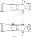
- the universal interface is depicted in Figures 12 and 13 .
- the universal interface is a slide fit and works with a large variety of housing designs within a certain class (e.g. 30mil tubes).
- the 'non-threaded' / 'non-bayonet' - mechanical interface is able to bridge a wide tolerance field (compared to thread- or bayonet standards).
- the universal interface includes one or more locking o-rings 72 within a sleeve 74 of the ocular housing. The o-rings are retained between stops 77, 78.
- a tightening locking ring 76 moves laterally within the sleeve 74. As the locking ring 76 moves within the sleeve, it compresses the o-rings 72 causing the o-rings to expand radially ( Figure 13 ), thereby providing engagement between the internal sleeve wall of the ocular housing and the outer surface of the main housing. Further description of the universal interface is provided in the Applicant's co-pending patent application titled "Scope Attachment" (Attorney Docket No.: 1046.9811), the entire contents of which are incorporated herein by reference.
- An advantage of the universal interface is that it can reduce cost for riflescope manufacturers to develop a riflescope that can adapt to the concepts described herein.
Landscapes
- Physics & Mathematics (AREA)
- Optics & Photonics (AREA)
- Engineering & Computer Science (AREA)
- General Engineering & Computer Science (AREA)
- Telescopes (AREA)
Claims (13)
- Lunette de visée comprenant(A) un premier boîtier principal (12),(B) un groupe d'objectifs (20) comprenant au moins une lentille d'objectif dirigeant la lumière (23) vers un premier plan image (24), le groupe d'objectifs étant disposé vers un bout d'objectif (13) du boîtier principal (12) ;(C) un premier réticule (26) comprenant au moins un repère matériel de réticule (40),
caractérisé en ce que
le premier réticule (26) disposé dans ou près du premier plan image (24) comprend au moins un repère (45, 48) qui n'est pas visible pour un opérateur de la lunette de visée (10) pendant l'usage normal de la lunette de visée (10); et(D) un groupe digital oculaire (30) détachable, comprenant :(a) un second boîtier (38) attachable à et détachable d'un bout oculaire (14) du boîtier principal ;(b) un capteur d'images (31) disposé à un second plan image (37) ;(c) au moins un processeur (34), ledit au moins un repère (45, 48) étant détectable par ledit au moins un processeur (34) au moyen du capteur d'images (31) ;(d) un affichage digital (33) ;(e) une alimentation en énergie pour alimenter en énergie ledit au moins un processeur (34) et/ou l'affichage digital (33) ; et(f) le capteur d'images (31) étant configuré pour recevoir une image représentative de la lumière (23) ayant entrée dans le bout d'objectif (13) du boîtier principal (12), le processeur (34) étant configuré pour traiter l'image reçue par le capteur d'images (31) et pour afficher une image représentative de la lumière reçue sur l'affichage digital (33), le processeur (34) étant programmé pour recouvrir ledit au moins un repère matériel de réticule (40) digitalement avec un ou plusieurs repères de cible secondaires (51, 53, 55) dans le second plan image (37). - Lunette de visée (10) selon la revendication 1, le groupe digital oculaire détachable (30) étant remplaçable avec un groupe oculaire sans énergie (20) comprenant un troisième boîtier (16) attachable à et détachable d'un bout oculaire (14) du premier boîtier principal (12) et un ou plusieurs seconds éléments oculaires optiques (17) disposés dans le troisième boîtier (16).
- Lunette de visée (10) selon la revendication 1, comprenant un groupe d'éléments inversibles (28) comprenant au moins un élément optique inversible.
- Lunette de visée (10) selon la revendication 1, le groupe digital oculaire détachable (30) comprenant un ou plusieurs éléments oculaires optiques (35) pour magnifier l'affichage digital (33) pour projeter celui-ci à un utilisateur au moyen d'un bout oculaire (14) du second boîtier (38).
- Lunette de visée (10) selon la revendication 1, l'affichage digital (33) comprenant un affichage de seuil très bas pour éviter d'aveugler l'oeil d'un utilisateur dans des conditions de très faible luminosité.
- Lunette de visée (10) selon la revendication 1, au moins un processeur (34) étant programmé pour supprimer ledit au moins un repère matériel (40).
- Lunette de visée (10) selon la revendication 1, au moins un repère (45, 48) comprenant un repère actif qui est activé par au moins un activateur (39).
- Lunette de visée (10) selon la revendication 7, le repère actif (45, 48) comprenant au moins un repère infrarouge, le groupe digital oculaire détachable (30) comprenant au moins une source de lumière infrarouge (39) qui peut être activée sélectivement pour illuminer ledit au moins un repère infrarouge (45, 48).
- Lunette de visée (10) selon la revendication 1, ledit au moins un processeur (34) étant programmé pour effectuer une procédure de calibrage comprenant les étapes suivantes :(A) recevoir la lumière du repère (45, 48) dans le capteur d'images (31) ;(B) traiter, par le processeur (34), l'image reçue par le capteur d'images (31) pour détecter une location du repère (45, 48) ; et(C) calibrer, par le processeur (34), l'affichage digital (33) à partir de la location détectée du repère (45, 48).
- Lunette de visée (10) selon la revendication 9, la procédure de calibrage comprenant l'activation (39) du repère (45, 48).
- Lunette de visée (10) selon la revendication 9, le processeur (34) étant programmé pour effectuer le calibrage automatiquement périodiquement.
- Procédé pour calibrer une lunette de visée (10) selon la revendication 1, comprenant un réticule (26), un capteur d'images (31), au moins un processeur (34) et un affichage digital (33), le réticule (26) comprenant au moins un repère (45, 48) qui n'est pas visible pour un opérateur de la lunette de visée (10) pendant l'usage normal de la lunette de visée (10), ledit au moins un repère (45, 48) étant détectable par ledit au moins un processeur (34) au moyen du capteur d'images (31),
le procédé comprenant les étapes suivantes :(A) recevoir la lumière du repère (45, 48) dans le capteur d'images (31) dans un plan image (24) du réticule (26) ;(B) traiter, par ledit au moins un processeur (34), l'image reçue par le capteur d'images (31) pour détecter une location de repère (45, 48),
le processeur (34) étant programmé pour recouvrir ledit au moins un repère matériel de réticule (40) digitalement avec un ou plusieurs repères de cible secondaires (51, 53, 55) dans le second plan image (37) ; et(C) calibrer, par le processeur (34), l'affichage digital (33) à partir de la location détectée du repère (45, 48). - Procédé selon la revendication 12, comprenant l'activation d'une source de lumière (39) pour illuminer le repère.
Applications Claiming Priority (3)
| Application Number | Priority Date | Filing Date | Title |
|---|---|---|---|
| US201461945080P | 2014-02-26 | 2014-02-26 | |
| US201461982253P | 2014-04-21 | 2014-04-21 | |
| PCT/IB2015/000986 WO2015128745A2 (fr) | 2014-02-26 | 2015-02-25 | Dispositif de réglage de portée |
Publications (3)
| Publication Number | Publication Date |
|---|---|
| EP3111155A2 EP3111155A2 (fr) | 2017-01-04 |
| EP3111155A4 EP3111155A4 (fr) | 2017-09-27 |
| EP3111155B1 true EP3111155B1 (fr) | 2018-12-19 |
Family
ID=53881882
Family Applications (1)
| Application Number | Title | Priority Date | Filing Date |
|---|---|---|---|
| EP15755342.1A Not-in-force EP3111155B1 (fr) | 2014-02-26 | 2015-02-25 | Dispositif de réglage de portée |
Country Status (3)
| Country | Link |
|---|---|
| US (1) | US9651338B2 (fr) |
| EP (1) | EP3111155B1 (fr) |
| WO (1) | WO2015128745A2 (fr) |
Families Citing this family (5)
| Publication number | Priority date | Publication date | Assignee | Title |
|---|---|---|---|---|
| DE102018125142A1 (de) | 2017-10-11 | 2019-04-11 | Sig Sauer, Inc. | Ballistisches zielsystem mit digitalem absehen |
| DE102018133064A1 (de) | 2017-12-20 | 2019-07-04 | Sig Sauer Inc. | Ballistisches Zielsystem mit digitalem Verstellrad |
| US11454473B2 (en) | 2020-01-17 | 2022-09-27 | Sig Sauer, Inc. | Telescopic sight having ballistic group storage |
| US11913754B2 (en) * | 2023-05-17 | 2024-02-27 | Peng Wang | Telescopic sight for detachably connecting night vison device and night vision equipment |
| US12222190B2 (en) | 2024-01-30 | 2025-02-11 | Nantong Yilong Machinery Manufacturing Co., Ltd. | Portable scope magnification quick-adjustment device |
Family Cites Families (29)
| Publication number | Priority date | Publication date | Assignee | Title |
|---|---|---|---|---|
| US2392979A (en) * | 1942-10-31 | 1946-01-15 | Rca Corp | Luminous reticle |
| US5497266A (en) * | 1994-07-27 | 1996-03-05 | Litton Systems, Inc. | Telescopic day and night sight |
| US5824942A (en) * | 1996-01-22 | 1998-10-20 | Raytheon Company | Method and device for fire control of a high apogee trajectory weapon |
| US6862832B2 (en) * | 2002-07-17 | 2005-03-08 | Ronnie G. Barrett | Digital elevation knob |
| US7292262B2 (en) * | 2003-07-21 | 2007-11-06 | Raytheon Company | Electronic firearm sight, and method of operating same |
| US20050268521A1 (en) * | 2004-06-07 | 2005-12-08 | Raytheon Company | Electronic sight for firearm, and method of operating same |
| US20060010760A1 (en) | 2004-06-14 | 2006-01-19 | Perkins William C | Telescopic sight and method for automatically compensating for bullet trajectory deviations |
| AT414167B (de) * | 2004-08-18 | 2006-09-15 | Kahles Ges M B H | Betätigungselement für ein zielfernrohr |
| AT413884B (de) * | 2004-08-18 | 2006-07-15 | Kahles Ges M B H | Betätigungselement für ein zielfernrohr |
| US7210262B2 (en) * | 2004-12-23 | 2007-05-01 | Raytheon Company | Method and apparatus for safe operation of an electronic firearm sight depending upon detected ambient illumination |
| US7121036B1 (en) * | 2004-12-23 | 2006-10-17 | Raytheon Company | Method and apparatus for safe operation of an electronic firearm sight depending upon the detection of a selected color |
| US7124531B1 (en) * | 2004-12-23 | 2006-10-24 | Raytheon Company | Method and apparatus for safe operation of an electronic firearm sight |
| EP1748273A1 (fr) | 2005-07-25 | 2007-01-31 | Bushnell Performance Optics | Lunette de visée et méthode de correction de déviation de trajectoire de projectile |
| US8081291B2 (en) * | 2006-01-12 | 2011-12-20 | Teledyne Licensing, Llc | Electro-optic zoom lens system |
| US8091268B2 (en) | 2006-02-09 | 2012-01-10 | Leupold & Stevens, Inc. | Multi-color reticle for ballistic aiming |
| JP4573218B2 (ja) | 2006-06-09 | 2010-11-04 | 株式会社デンソー | 燃料噴射装置 |
| US8064132B1 (en) * | 2008-06-18 | 2011-11-22 | Vectronix, Inc. | Binoculars with adaptive reticle display and associated methods |
| US20110207089A1 (en) * | 2010-02-25 | 2011-08-25 | Lagettie David Alfred A | Firearm training systems and methods of using the same |
| US8336776B2 (en) | 2010-06-30 | 2012-12-25 | Trijicon, Inc. | Aiming system for weapon |
| WO2012068423A2 (fr) * | 2010-11-18 | 2012-05-24 | David Rudich | Visée d'arme à feu ayant une caméra vidéo uhd |
| US9046322B2 (en) * | 2010-11-22 | 2015-06-02 | Pfg Ip Llc | Self-calibrating targeting sight |
| WO2013002856A2 (fr) * | 2011-04-01 | 2013-01-03 | Zrf, Llc | Système et procédé de visée automatique d'une arme |
| US8881981B2 (en) | 2012-03-05 | 2014-11-11 | James A. Millett | Digital targeting scope apparatus |
| US8807430B2 (en) | 2012-03-05 | 2014-08-19 | James Allen Millett | Dscope aiming device |
| US9250036B2 (en) | 2012-03-05 | 2016-02-02 | Burris Company, Inc. | Optical device utilizing ballistic zoom and methods for sighting a target |
| DE202012002286U1 (de) * | 2012-03-08 | 2013-06-10 | Carl Zeiss Sports Optics Gmbh | Betätigungselement für die Verstellung oder Einstellung eines Parameters eines optischen Geräts, insbesondere Absehenschnellverstellung für ein Zielfernrohr |
| US20140041277A1 (en) * | 2012-08-08 | 2014-02-13 | Sheltered Wings, Inc. | Advanced illuminated reticle |
| US9903688B2 (en) * | 2013-11-08 | 2018-02-27 | Supas Ltd | Scope |
| US20150138633A1 (en) * | 2013-11-21 | 2015-05-21 | Supas Ltd | Scope attachment |
-
2015
- 2015-02-25 WO PCT/IB2015/000986 patent/WO2015128745A2/fr not_active Ceased
- 2015-02-25 US US14/630,903 patent/US9651338B2/en active Active
- 2015-02-25 EP EP15755342.1A patent/EP3111155B1/fr not_active Not-in-force
Non-Patent Citations (1)
| Title |
|---|
| None * |
Also Published As
| Publication number | Publication date |
|---|---|
| WO2015128745A3 (fr) | 2016-05-19 |
| EP3111155A4 (fr) | 2017-09-27 |
| US9651338B2 (en) | 2017-05-16 |
| US20150241171A1 (en) | 2015-08-27 |
| EP3111155A2 (fr) | 2017-01-04 |
| WO2015128745A2 (fr) | 2015-09-03 |
Similar Documents
| Publication | Publication Date | Title |
|---|---|---|
| US12031796B2 (en) | Optical system with cant indication | |
| EP3516448B1 (fr) | Système de projection d'informations de ciblage optique pour des endoscopes de visée de système d'arme et systèmes associés | |
| US11287638B2 (en) | Reflex sight with superluminescent micro-display, dynamic reticle, and metadata overlay | |
| KR102839477B1 (ko) | 통합 디스플레이 시스템을 구비하는 관찰 광학 장치 | |
| US10775134B2 (en) | Telescopic sight having fast reticle adjustment | |
| US8074394B2 (en) | Riflescope with image stabilization | |
| EP3111155B1 (fr) | Dispositif de réglage de portée | |
| AU2011285873B2 (en) | Optical Sight | |
| AU2011202780B2 (en) | Aiming system for weapon | |
| US11060816B2 (en) | Digital turret ballistic aiming system | |
| US20140115942A1 (en) | Synchronized elevation trajectory riflescope | |
| KR20210013046A (ko) | 직접 능동 레티클 표적화를 구비하는 시야 광학체 | |
| CN104246420A (zh) | D型望远瞄准装置 | |
| EP3210067B1 (fr) | Système de visée comprenant un indicateur de grossissement variable | |
| KR20240029762A (ko) | 이미저 및 무기 시스템 조준기를 위한 디지털 초점면 정렬 시스템 및 방법 | |
| EP3280969B1 (fr) | Monture d'adaptateur d'écran de ciblage de lunette de visée pour arme d'épaule | |
| US9945637B1 (en) | Scope and method for sighting-in a firearm | |
| US20260118091A1 (en) | Optical sight and information display method | |
| DK2402704T3 (en) | Aiming system for weapons |
Legal Events
| Date | Code | Title | Description |
|---|---|---|---|
| PUAI | Public reference made under article 153(3) epc to a published international application that has entered the european phase |
Free format text: ORIGINAL CODE: 0009012 |
|
| STAA | Information on the status of an ep patent application or granted ep patent |
Free format text: STATUS: REQUEST FOR EXAMINATION WAS MADE |
|
| 17P | Request for examination filed |
Effective date: 20160908 |
|
| AK | Designated contracting states |
Kind code of ref document: A2 Designated state(s): AL AT BE BG CH CY CZ DE DK EE ES FI FR GB GR HR HU IE IS IT LI LT LU LV MC MK MT NL NO PL PT RO RS SE SI SK SM TR |
|
| AX | Request for extension of the european patent |
Extension state: BA ME |
|
| DAX | Request for extension of the european patent (deleted) | ||
| A4 | Supplementary search report drawn up and despatched |
Effective date: 20170828 |
|
| RIC1 | Information provided on ipc code assigned before grant |
Ipc: F41G 1/38 20060101AFI20170822BHEP |
|
| GRAP | Despatch of communication of intention to grant a patent |
Free format text: ORIGINAL CODE: EPIDOSNIGR1 |
|
| STAA | Information on the status of an ep patent application or granted ep patent |
Free format text: STATUS: GRANT OF PATENT IS INTENDED |
|
| INTG | Intention to grant announced |
Effective date: 20180720 |
|
| GRAS | Grant fee paid |
Free format text: ORIGINAL CODE: EPIDOSNIGR3 |
|
| GRAA | (expected) grant |
Free format text: ORIGINAL CODE: 0009210 |
|
| STAA | Information on the status of an ep patent application or granted ep patent |
Free format text: STATUS: THE PATENT HAS BEEN GRANTED |
|
| AK | Designated contracting states |
Kind code of ref document: B1 Designated state(s): AL AT BE BG CH CY CZ DE DK EE ES FI FR GB GR HR HU IE IS IT LI LT LU LV MC MK MT NL NO PL PT RO RS SE SI SK SM TR |
|
| REG | Reference to a national code |
Ref country code: DE Ref legal event code: R082 Ref document number: 602015021920 Country of ref document: DE Representative=s name: ADVOTEC. PATENT- UND RECHTSANWALTSPARTNERSCHAF, DE Ref country code: GB Ref legal event code: FG4D Ref country code: DE Ref legal event code: R082 Ref document number: 602015021920 Country of ref document: DE Representative=s name: ADVOTEC. PATENT- UND RECHTSANWAELTE, DE |
|
| REG | Reference to a national code |
Ref country code: CH Ref legal event code: EP |
|
| REG | Reference to a national code |
Ref country code: IE Ref legal event code: FG4D |
|
| REG | Reference to a national code |
Ref country code: DE Ref legal event code: R096 Ref document number: 602015021920 Country of ref document: DE |
|
| REG | Reference to a national code |
Ref country code: AT Ref legal event code: REF Ref document number: 1079192 Country of ref document: AT Kind code of ref document: T Effective date: 20190115 |
|
| REG | Reference to a national code |
Ref country code: NL Ref legal event code: MP Effective date: 20181219 |
|
| PG25 | Lapsed in a contracting state [announced via postgrant information from national office to epo] |
Ref country code: LV Free format text: LAPSE BECAUSE OF FAILURE TO SUBMIT A TRANSLATION OF THE DESCRIPTION OR TO PAY THE FEE WITHIN THE PRESCRIBED TIME-LIMIT Effective date: 20181219 Ref country code: FI Free format text: LAPSE BECAUSE OF FAILURE TO SUBMIT A TRANSLATION OF THE DESCRIPTION OR TO PAY THE FEE WITHIN THE PRESCRIBED TIME-LIMIT Effective date: 20181219 Ref country code: NO Free format text: LAPSE BECAUSE OF FAILURE TO SUBMIT A TRANSLATION OF THE DESCRIPTION OR TO PAY THE FEE WITHIN THE PRESCRIBED TIME-LIMIT Effective date: 20190319 Ref country code: LT Free format text: LAPSE BECAUSE OF FAILURE TO SUBMIT A TRANSLATION OF THE DESCRIPTION OR TO PAY THE FEE WITHIN THE PRESCRIBED TIME-LIMIT Effective date: 20181219 Ref country code: HR Free format text: LAPSE BECAUSE OF FAILURE TO SUBMIT A TRANSLATION OF THE DESCRIPTION OR TO PAY THE FEE WITHIN THE PRESCRIBED TIME-LIMIT Effective date: 20181219 Ref country code: BG Free format text: LAPSE BECAUSE OF FAILURE TO SUBMIT A TRANSLATION OF THE DESCRIPTION OR TO PAY THE FEE WITHIN THE PRESCRIBED TIME-LIMIT Effective date: 20190319 |
|
| REG | Reference to a national code |
Ref country code: LT Ref legal event code: MG4D |
|
| REG | Reference to a national code |
Ref country code: AT Ref legal event code: MK05 Ref document number: 1079192 Country of ref document: AT Kind code of ref document: T Effective date: 20181219 |
|
| PG25 | Lapsed in a contracting state [announced via postgrant information from national office to epo] |
Ref country code: RS Free format text: LAPSE BECAUSE OF FAILURE TO SUBMIT A TRANSLATION OF THE DESCRIPTION OR TO PAY THE FEE WITHIN THE PRESCRIBED TIME-LIMIT Effective date: 20181219 Ref country code: SE Free format text: LAPSE BECAUSE OF FAILURE TO SUBMIT A TRANSLATION OF THE DESCRIPTION OR TO PAY THE FEE WITHIN THE PRESCRIBED TIME-LIMIT Effective date: 20181219 Ref country code: GR Free format text: LAPSE BECAUSE OF FAILURE TO SUBMIT A TRANSLATION OF THE DESCRIPTION OR TO PAY THE FEE WITHIN THE PRESCRIBED TIME-LIMIT Effective date: 20190320 Ref country code: AL Free format text: LAPSE BECAUSE OF FAILURE TO SUBMIT A TRANSLATION OF THE DESCRIPTION OR TO PAY THE FEE WITHIN THE PRESCRIBED TIME-LIMIT Effective date: 20181219 |
|
| PG25 | Lapsed in a contracting state [announced via postgrant information from national office to epo] |
Ref country code: NL Free format text: LAPSE BECAUSE OF FAILURE TO SUBMIT A TRANSLATION OF THE DESCRIPTION OR TO PAY THE FEE WITHIN THE PRESCRIBED TIME-LIMIT Effective date: 20181219 |
|
| PG25 | Lapsed in a contracting state [announced via postgrant information from national office to epo] |
Ref country code: ES Free format text: LAPSE BECAUSE OF FAILURE TO SUBMIT A TRANSLATION OF THE DESCRIPTION OR TO PAY THE FEE WITHIN THE PRESCRIBED TIME-LIMIT Effective date: 20181219 Ref country code: PT Free format text: LAPSE BECAUSE OF FAILURE TO SUBMIT A TRANSLATION OF THE DESCRIPTION OR TO PAY THE FEE WITHIN THE PRESCRIBED TIME-LIMIT Effective date: 20190419 Ref country code: PL Free format text: LAPSE BECAUSE OF FAILURE TO SUBMIT A TRANSLATION OF THE DESCRIPTION OR TO PAY THE FEE WITHIN THE PRESCRIBED TIME-LIMIT Effective date: 20181219 Ref country code: CZ Free format text: LAPSE BECAUSE OF FAILURE TO SUBMIT A TRANSLATION OF THE DESCRIPTION OR TO PAY THE FEE WITHIN THE PRESCRIBED TIME-LIMIT Effective date: 20181219 Ref country code: IT Free format text: LAPSE BECAUSE OF FAILURE TO SUBMIT A TRANSLATION OF THE DESCRIPTION OR TO PAY THE FEE WITHIN THE PRESCRIBED TIME-LIMIT Effective date: 20181219 |
|
| PG25 | Lapsed in a contracting state [announced via postgrant information from national office to epo] |
Ref country code: IS Free format text: LAPSE BECAUSE OF FAILURE TO SUBMIT A TRANSLATION OF THE DESCRIPTION OR TO PAY THE FEE WITHIN THE PRESCRIBED TIME-LIMIT Effective date: 20190419 Ref country code: SK Free format text: LAPSE BECAUSE OF FAILURE TO SUBMIT A TRANSLATION OF THE DESCRIPTION OR TO PAY THE FEE WITHIN THE PRESCRIBED TIME-LIMIT Effective date: 20181219 Ref country code: RO Free format text: LAPSE BECAUSE OF FAILURE TO SUBMIT A TRANSLATION OF THE DESCRIPTION OR TO PAY THE FEE WITHIN THE PRESCRIBED TIME-LIMIT Effective date: 20181219 Ref country code: EE Free format text: LAPSE BECAUSE OF FAILURE TO SUBMIT A TRANSLATION OF THE DESCRIPTION OR TO PAY THE FEE WITHIN THE PRESCRIBED TIME-LIMIT Effective date: 20181219 Ref country code: SM Free format text: LAPSE BECAUSE OF FAILURE TO SUBMIT A TRANSLATION OF THE DESCRIPTION OR TO PAY THE FEE WITHIN THE PRESCRIBED TIME-LIMIT Effective date: 20181219 |
|
| REG | Reference to a national code |
Ref country code: DE Ref legal event code: R097 Ref document number: 602015021920 Country of ref document: DE |
|
| REG | Reference to a national code |
Ref country code: CH Ref legal event code: PL |
|
| PLBE | No opposition filed within time limit |
Free format text: ORIGINAL CODE: 0009261 |
|
| STAA | Information on the status of an ep patent application or granted ep patent |
Free format text: STATUS: NO OPPOSITION FILED WITHIN TIME LIMIT |
|
| PG25 | Lapsed in a contracting state [announced via postgrant information from national office to epo] |
Ref country code: MC Free format text: LAPSE BECAUSE OF FAILURE TO SUBMIT A TRANSLATION OF THE DESCRIPTION OR TO PAY THE FEE WITHIN THE PRESCRIBED TIME-LIMIT Effective date: 20181219 Ref country code: AT Free format text: LAPSE BECAUSE OF FAILURE TO SUBMIT A TRANSLATION OF THE DESCRIPTION OR TO PAY THE FEE WITHIN THE PRESCRIBED TIME-LIMIT Effective date: 20181219 Ref country code: DK Free format text: LAPSE BECAUSE OF FAILURE TO SUBMIT A TRANSLATION OF THE DESCRIPTION OR TO PAY THE FEE WITHIN THE PRESCRIBED TIME-LIMIT Effective date: 20181219 Ref country code: LU Free format text: LAPSE BECAUSE OF NON-PAYMENT OF DUE FEES Effective date: 20190225 |
|
| REG | Reference to a national code |
Ref country code: BE Ref legal event code: MM Effective date: 20190228 |
|
| 26N | No opposition filed |
Effective date: 20190920 |
|
| REG | Reference to a national code |
Ref country code: IE Ref legal event code: MM4A |
|
| PG25 | Lapsed in a contracting state [announced via postgrant information from national office to epo] |
Ref country code: LI Free format text: LAPSE BECAUSE OF NON-PAYMENT OF DUE FEES Effective date: 20190228 Ref country code: CH Free format text: LAPSE BECAUSE OF NON-PAYMENT OF DUE FEES Effective date: 20190228 |
|
| PG25 | Lapsed in a contracting state [announced via postgrant information from national office to epo] |
Ref country code: IE Free format text: LAPSE BECAUSE OF NON-PAYMENT OF DUE FEES Effective date: 20190225 |
|
| PG25 | Lapsed in a contracting state [announced via postgrant information from national office to epo] |
Ref country code: BE Free format text: LAPSE BECAUSE OF NON-PAYMENT OF DUE FEES Effective date: 20190228 Ref country code: SI Free format text: LAPSE BECAUSE OF FAILURE TO SUBMIT A TRANSLATION OF THE DESCRIPTION OR TO PAY THE FEE WITHIN THE PRESCRIBED TIME-LIMIT Effective date: 20181219 |
|
| PG25 | Lapsed in a contracting state [announced via postgrant information from national office to epo] |
Ref country code: TR Free format text: LAPSE BECAUSE OF FAILURE TO SUBMIT A TRANSLATION OF THE DESCRIPTION OR TO PAY THE FEE WITHIN THE PRESCRIBED TIME-LIMIT Effective date: 20181219 |
|
| PG25 | Lapsed in a contracting state [announced via postgrant information from national office to epo] |
Ref country code: MT Free format text: LAPSE BECAUSE OF NON-PAYMENT OF DUE FEES Effective date: 20190225 |
|
| PG25 | Lapsed in a contracting state [announced via postgrant information from national office to epo] |
Ref country code: CY Free format text: LAPSE BECAUSE OF FAILURE TO SUBMIT A TRANSLATION OF THE DESCRIPTION OR TO PAY THE FEE WITHIN THE PRESCRIBED TIME-LIMIT Effective date: 20181219 |
|
| PG25 | Lapsed in a contracting state [announced via postgrant information from national office to epo] |
Ref country code: HU Free format text: LAPSE BECAUSE OF FAILURE TO SUBMIT A TRANSLATION OF THE DESCRIPTION OR TO PAY THE FEE WITHIN THE PRESCRIBED TIME-LIMIT; INVALID AB INITIO Effective date: 20150225 |
|
| PG25 | Lapsed in a contracting state [announced via postgrant information from national office to epo] |
Ref country code: MK Free format text: LAPSE BECAUSE OF FAILURE TO SUBMIT A TRANSLATION OF THE DESCRIPTION OR TO PAY THE FEE WITHIN THE PRESCRIBED TIME-LIMIT Effective date: 20181219 |
|
| PGFP | Annual fee paid to national office [announced via postgrant information from national office to epo] |
Ref country code: FR Payment date: 20230220 Year of fee payment: 9 |
|
| PGFP | Annual fee paid to national office [announced via postgrant information from national office to epo] |
Ref country code: GB Payment date: 20230221 Year of fee payment: 9 |
|
| PGFP | Annual fee paid to national office [announced via postgrant information from national office to epo] |
Ref country code: DE Payment date: 20230420 Year of fee payment: 9 |
|
| REG | Reference to a national code |
Ref country code: DE Ref legal event code: R119 Ref document number: 602015021920 Country of ref document: DE |
|
| GBPC | Gb: european patent ceased through non-payment of renewal fee |
Effective date: 20240225 |
|
| PG25 | Lapsed in a contracting state [announced via postgrant information from national office to epo] |
Ref country code: DE Free format text: LAPSE BECAUSE OF NON-PAYMENT OF DUE FEES Effective date: 20240903 |
|
| PG25 | Lapsed in a contracting state [announced via postgrant information from national office to epo] |
Ref country code: GB Free format text: LAPSE BECAUSE OF NON-PAYMENT OF DUE FEES Effective date: 20240225 |
|
| PG25 | Lapsed in a contracting state [announced via postgrant information from national office to epo] |
Ref country code: FR Free format text: LAPSE BECAUSE OF NON-PAYMENT OF DUE FEES Effective date: 20240229 |
|
| PG25 | Lapsed in a contracting state [announced via postgrant information from national office to epo] |
Ref country code: GB Free format text: LAPSE BECAUSE OF NON-PAYMENT OF DUE FEES Effective date: 20240225 Ref country code: FR Free format text: LAPSE BECAUSE OF NON-PAYMENT OF DUE FEES Effective date: 20240229 Ref country code: DE Free format text: LAPSE BECAUSE OF NON-PAYMENT OF DUE FEES Effective date: 20240903 |