EP3111187B1 - Glühkerzenadapter - Google Patents
Glühkerzenadapter Download PDFInfo
- Publication number
- EP3111187B1 EP3111187B1 EP15706140.9A EP15706140A EP3111187B1 EP 3111187 B1 EP3111187 B1 EP 3111187B1 EP 15706140 A EP15706140 A EP 15706140A EP 3111187 B1 EP3111187 B1 EP 3111187B1
- Authority
- EP
- European Patent Office
- Prior art keywords
- adaptor
- glow
- plug
- combustion chamber
- head
- Prior art date
- Legal status (The legal status is an assumption and is not a legal conclusion. Google has not performed a legal analysis and makes no representation as to the accuracy of the status listed.)
- Not-in-force
Links
- 238000002485 combustion reaction Methods 0.000 claims description 58
- 238000005259 measurement Methods 0.000 claims description 8
- 238000007789 sealing Methods 0.000 claims description 8
- 239000007789 gas Substances 0.000 description 12
- 239000012528 membrane Substances 0.000 description 10
- 238000009530 blood pressure measurement Methods 0.000 description 5
- 238000010276 construction Methods 0.000 description 3
- 239000000523 sample Substances 0.000 description 2
- 238000011144 upstream manufacturing Methods 0.000 description 2
- 230000002411 adverse Effects 0.000 description 1
- 230000005540 biological transmission Effects 0.000 description 1
- 239000000919 ceramic Substances 0.000 description 1
- 239000000567 combustion gas Substances 0.000 description 1
- 238000010438 heat treatment Methods 0.000 description 1
- 238000002955 isolation Methods 0.000 description 1
- 238000013021 overheating Methods 0.000 description 1
- 230000010076 replication Effects 0.000 description 1
- 238000004904 shortening Methods 0.000 description 1
Images
Classifications
-
- G—PHYSICS
- G01—MEASURING; TESTING
- G01L—MEASURING FORCE, STRESS, TORQUE, WORK, MECHANICAL POWER, MECHANICAL EFFICIENCY, OR FLUID PRESSURE
- G01L19/00—Details of, or accessories for, apparatus for measuring steady or quasi-steady pressure of a fluent medium insofar as such details or accessories are not special to particular types of pressure gauges
- G01L19/06—Means for preventing overload or deleterious influence of the measured medium on the measuring device or vice versa
- G01L19/0681—Protection against excessive heat
-
- F—MECHANICAL ENGINEERING; LIGHTING; HEATING; WEAPONS; BLASTING
- F23—COMBUSTION APPARATUS; COMBUSTION PROCESSES
- F23Q—IGNITION; EXTINGUISHING-DEVICES
- F23Q7/00—Incandescent ignition; Igniters using electrically-produced heat, e.g. lighters for cigarettes; Electrically-heated glowing plugs
- F23Q7/001—Glowing plugs for internal-combustion engines
-
- G—PHYSICS
- G01—MEASURING; TESTING
- G01L—MEASURING FORCE, STRESS, TORQUE, WORK, MECHANICAL POWER, MECHANICAL EFFICIENCY, OR FLUID PRESSURE
- G01L23/00—Devices or apparatus for measuring or indicating or recording rapid changes, such as oscillations, in the pressure of steam, gas, or liquid; Indicators for determining work or energy of steam, internal-combustion, or other fluid-pressure engines from the condition of the working fluid
- G01L23/08—Devices or apparatus for measuring or indicating or recording rapid changes, such as oscillations, in the pressure of steam, gas, or liquid; Indicators for determining work or energy of steam, internal-combustion, or other fluid-pressure engines from the condition of the working fluid operated electrically
- G01L23/10—Devices or apparatus for measuring or indicating or recording rapid changes, such as oscillations, in the pressure of steam, gas, or liquid; Indicators for determining work or energy of steam, internal-combustion, or other fluid-pressure engines from the condition of the working fluid operated electrically by pressure-sensitive members of the piezoelectric type
-
- G—PHYSICS
- G01—MEASURING; TESTING
- G01L—MEASURING FORCE, STRESS, TORQUE, WORK, MECHANICAL POWER, MECHANICAL EFFICIENCY, OR FLUID PRESSURE
- G01L23/00—Devices or apparatus for measuring or indicating or recording rapid changes, such as oscillations, in the pressure of steam, gas, or liquid; Indicators for determining work or energy of steam, internal-combustion, or other fluid-pressure engines from the condition of the working fluid
- G01L23/22—Devices or apparatus for measuring or indicating or recording rapid changes, such as oscillations, in the pressure of steam, gas, or liquid; Indicators for determining work or energy of steam, internal-combustion, or other fluid-pressure engines from the condition of the working fluid for detecting or indicating knocks in internal-combustion engines; Units comprising pressure-sensitive members combined with ignitors for firing internal-combustion engines
-
- G—PHYSICS
- G01—MEASURING; TESTING
- G01L—MEASURING FORCE, STRESS, TORQUE, WORK, MECHANICAL POWER, MECHANICAL EFFICIENCY, OR FLUID PRESSURE
- G01L9/00—Measuring steady of quasi-steady pressure of fluid or fluent solid material by electric or magnetic pressure-sensitive elements; Transmitting or indicating the displacement of mechanical pressure-sensitive elements, used to measure the steady or quasi-steady pressure of a fluid or fluent solid material, by electric or magnetic means
- G01L9/0041—Transmitting or indicating the displacement of flexible diaphragms
- G01L9/008—Transmitting or indicating the displacement of flexible diaphragms using piezoelectric devices
-
- F—MECHANICAL ENGINEERING; LIGHTING; HEATING; WEAPONS; BLASTING
- F23—COMBUSTION APPARATUS; COMBUSTION PROCESSES
- F23Q—IGNITION; EXTINGUISHING-DEVICES
- F23Q7/00—Incandescent ignition; Igniters using electrically-produced heat, e.g. lighters for cigarettes; Electrically-heated glowing plugs
- F23Q7/001—Glowing plugs for internal-combustion engines
- F23Q2007/002—Glowing plugs for internal-combustion engines with sensing means
Definitions
- the invention relates to a glow plug adapter for pressure measurement in a combustion chamber of an internal combustion engine, comprising an adapter head, in which a pressure sensor is mounted with a membrane and an adapter sleeve which is attached to the adapter head, wherein the glow plug adapter having a sealing shoulder having pressure-tight screwed into a glow plug bore in a combustion chamber wall and signal lines are led out of the pressure sensor through the adapter sleeve from the glow plug adapter.
- the invention also relates to a glow plug adapter, which is arranged pressure-tight in a glow plug bore in the combustion chamber wall.
- Adapters for attaching pressure probes to internal combustion engines are manufactured and sold as ignition or glow plug adapters, the geometry of the glow plug adapter usually corresponds to a glow plug.
- the glow plug adapter In order to adapt the glow plug adapter to the required geometry, known from the prior art glow plug adapter adapter tips, as known in glow plugs.
- a glow plug adapter which has a metallic or ceramic adapter tip, which is upstream of a piezoelectric pressure sensor on the combustion chamber side. The pressure acting on the glow plug is transmitted to the pressure sensor and thereby measured.
- the glow plug adapter can also be fastened in a glow plug bore in a combustion chamber wall instead of a glow plug.
- the glow plug adapter has an adapter head, which is designed substantially cylindrical, has a sealing cone and a sealing seat forming in the glow plug bore can be fastened.
- the pressure sensor is designed as an uncooled high-temperature pressure sensor, comprising a movable diaphragm on which the gas pressure of the combustion chamber acts directly. The membrane is brought as close as possible to the combustion chamber, whereby the measurement accuracy is increased.
- the adapter head of the glow plug adapter has an adapter tip attached to it for the most accurate replication of the tip of a glow plug.
- the adapter tip is modeled according to the contour of the tip of the glow plug and attached to the combustion chamber end of the glow plug adapter on the adapter head cohesively insoluble.
- As an adapter tip is a rigid device understood, which is attached to the combustion chamber end of the adapter head and the pressure sensor is upstream of the combustion chamber side.
- the adapter tip protrudes in the assembled state into the combustion chamber, analogous to the arrangement of a Glow plug.
- several gas exchange channels are provided, which lead into a cavity in front of the diaphragm of the pressure sensor. Since only a narrow gap remains between the adapter tip and the combustion chamber wall in the narrow glow plug bores, the heat flow on the combustion chamber side is restricted.
- Object of the present invention solved by claim 1, is to describe a glow plug adapter described above for pressure measurement in the combustion chamber of internal combustion engines, especially diesel engines, which achieves a higher accuracy, with a higher life of a pressure sensor arranged therein.
- a glow plug adapter has to have an adapter tip to allow the gas flow within the combustion chamber in the pressure measurement as equal as possible, as if a glow plug would be used originally. This has surprisingly been found to be unnecessary. By omitting an adapter tip, the pressure sensor can be closer to the combustion chamber be brought, making the pressure measurement is more accurate. As measurements have shown, the thermal load when omitting the adapter tip is surprisingly not increased. Thanks to the shortening of the adapter head, the glow plug adapter can be completely mounted in the bore of the combustion chamber wall, without projecting into the combustion chamber. This also allows measurements with reduced thermal problems.
- the glow plug adapters are thus simpler in construction. They are not thermally stressed, provide improved pressure measurements and are easier and cheaper to produce.
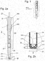
- FIG. 2a An inventive glow plug adapter 2 is in FIG. 2a shown in isolation in a sectional view.
- the entire contour of the glow plug adapter 2, apart from the tip, is modeled on a glow plug.
- the glow plug adapter 2 comprises an adapter sleeve 20 and an adapter head 21, wherein the adapter head 21 is welded to the adapter sleeve 20.
- Adapter head 21 and adapter sleeve 20 may also be screwed, pressed or glued.
- the glow plug adapter 2 extends from a combustion chamber remote end A to a combustion chamber near end B along a longitudinal axis L.
- the combustion chamber distal end A here has the shape of a hexagonal screw head 200.
- an external thread 201 is arranged.
- the glow plug adapter 2 can be fastened by a detachable connection of the external thread 201 in an operatively connected internal thread, as shown in FIG Fig. 3 is shown.
- the adapter head 21st In the region of the combustion chamber near end B of the glow plug adapter 2 is the adapter head 21st
- the pressure sensor 24 is designed to be uncooled and has, in addition to other components, a membrane 240 and a measuring element operatively connected to the membrane 240, the measuring element being connected to the membrane 240 for attaining the best measurement accuracy should be located as close to the membrane 240 as possible. In the optimal case, the measuring element is in direct contact with the membrane 240.
- the pressure sensor 24 is usually designed as a cylinder pressure sensor and extends into an adapter head interior, not shown.
- the pressure sensor 24 projects at least partially into the adapter head interior of the adapter head 21.
- the adapter head 21 is preferably configured in one piece, has a sealing shoulder 214 and is designed to taper towards the combustion chamber near end B and thus in the combustion chamber side region of the adapter head 21.
- the side walls 212 of the adapter head 21 are configured in the combustion chamber side region of the adapter head 21 is preferably frusto-conical, wherein the hollow interior of the adapter head 21 is closed with an end wall 211.
- the end wall 211 is executed in a plane perpendicular to the longitudinal axis L plan.
- a cavity 210 is formed in the interior of the adapter head 21, a cavity 210 is formed.
- the cavity 210 is closed at the combustion chamber near end B of the end wall 211 and direction adapter head interior of the diaphragm 240 of the pressure sensor 24.
- the adapter head 21 has an internal thread, which is operatively connected to an external thread of the sensor 24.
- the adapter head 21 is materially non-detachably connected to the adapter sleeve 20.
- the features of the adapter head 21 are highlighted.
- a plurality of gas exchange channels 213 are embedded, which here at an angle ⁇ between 30 ° and 90 °, preferably from about 60 ° to the longitudinal axis L extend.
- three gas exchange channels 213 are provided which lead into the cavity 210.
- the end wall thickness s is less than or equal to 3 mm.
- the front height l between the closed by the membrane 240 surface to the outer surface of the end wall 211 is smaller than an adapter diameter D of the adapter head 21 in the region of the cavity 210th
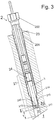
- the glow plug adapter 2 is instead of a glow plug in a glow plug bore 11 in a combustion chamber wall 10 of a combustion chamber 1 of an internal combustion engine, such as a diesel engine, introduced.
- the combustion chamber near end B of the glow plug adapter 2 is inserted into the glow plug bore 11 so far that the adapter head 21 comes to rest completely in the glow plug bore 11.
- the glow plug bore 11 is designed such that a taper of the diameter is formed on the combustion chamber 1 side facing. Adjacent to this taper in the glow plug bore 11, the sealing shoulder 214 of the adapter head 21 is placed, whereby a gas-tight fastening of the glow plug adapter 2 in the glow plug bore 11 is achieved.
- the external thread 201 on the adapter sleeve 20 engages in an internal thread of the glow plug bore 11, which is arranged in a side facing away from the combustion chamber 1 section.
- the adapter sleeve 20 together with the adapter head 21 can be screwed releasably connected by actuation of the hexagonal screw head 200.
- the signal lines 23 emerge from the adapter sleeve 20 outside of the glow plug bore 11 and can be connected to a measuring device.
- the geometry of the glow plug adapter 2 is adapted to the glow plug bore 11 such that the adapter head 21 does not project into the combustion chamber 1.
- the combustion chamber near end B of the glow plug adapter 2, in particular the adapter head 21 with the end wall 211, the cavity 210 and the gas exchange channels 213 are spaced from the combustion chamber 1 completely in the glow plug bore 11.
- the glow plug adapter 2 is thus set back in the glow plug bore 11 so arranged that the adapter head 21 does not protrude into the combustion chamber.
- the distance t between a central point in the amount of the longitudinal axis L on the outer surface of the end wall 211 and the end of the glow plug bore 11 is thus greater than zero selected.
- the distance t greater than zero and less than 10 mm is preferably selected, which leads to the best measurement results.
- the gap 215 between the side walls 212 of the adapter head 21 and the inner wall of the glow plug bore 11 has a small gap.
- the adapter head 21 is formed so that the gap is less than 0.05 mm.
- the end wall 211 is designed to be closed and the adapter head 21 in the glow plug bore 11 is set back from the combustion chamber 1.
- the combustion gases can easily pass through the gas exchange channels 213 to the membrane 240, at which the actual gas pressure can be precisely measured by means of a measuring element.
- the distance t can be varied only in a small range.
- the free volume in the glow plug bore 11 in front of the adapter head 21 is greatly increased compared to the prior art.
- the gas stream passes in the embodiment of the inventive solution faster resp. easier on the gas exchange channels 213, which causes a higher accuracy and lifetime of the pressure sensor 24.
Landscapes
- Engineering & Computer Science (AREA)
- Chemical & Material Sciences (AREA)
- Combustion & Propulsion (AREA)
- Physics & Mathematics (AREA)
- General Physics & Mathematics (AREA)
- Mechanical Engineering (AREA)
- General Engineering & Computer Science (AREA)
- Measuring Fluid Pressure (AREA)
Description
- Die Erfindung betrifft einen Glühkerzenadapter zur Druckmessung in einem Brennraum eines Verbrennungsmotors, umfassend einen Adapterkopf, in welchem ein Drucksensor mit einer Membran gelagert ist und eine Adapterhülse, die am Adapterkopf befestigt ist, wobei der Glühkerzenadapter eine Dichtschulter aufweisend druckdicht in eine Glühkerzenbohrung in einer Brennraumwand einschraubbar ist und Signalleitungen vom Drucksensor durch die Adapterhülse aus dem Glühkerzenadapter herausgeführt sind. Die Erfindung betrifft auch einen Glühkerzenadapter, welcher druckdicht in einer Glühkerzenbohrung in der Brennraumwand angeordnet ist.
- Adapter zum Anbringen von Druckmesssonden an Verbrennungsmotoren werden als Zünd- oder Glühkerzenadapter hergestellt und vertrieben, wobei die Geometrie des Glühkerzenadapters in der Regel einer Glühkerze entspricht. Um den Glühkerzenadapter an die geforderte Geometrie anzupassen, weisen aus dem Stand der Technik bekannte Glühkerzenadapter Adapterspitzen auf, wie bei Glühkerzen bekannt.
- In der
DE 102011088474 wird ein Glühkerzenadapter beschrieben, welcher eine metallische oder keramische Adapterspitze aufweist, die einem piezoelektrischen Drucksensor brennraumseitig vorgelagert ist. Der auf den Glühstift wirkende Druck wird auf den Drucksensor übertragen und dadurch gemessen. - Eine ähnliche Konstruktion ist in der
WO 2009/146565 beschrieben. In Längsrichtung auf eine Adapterspitze des Glühkerzenadapters wirkende Kräfte bzw. Drücke werden auf eine Membran eines piezoelektrischen Sensors übertragen und gemessen. Die Adapterspitze ist entsprechend bewegbar gelagert und wirkt jeweils als druckaufnehmendes Element, sodass Kräfte indirekt über die Adapterspitze auf die Membran des piezoelektrischen Sensors übertragen werden. Die erreichbare Messgenauigkeit dieser Anordnungen ist aufgrund der indirekten Kraftübertragung nicht optimal. - Eine andere Konstruktion ist im Glühkerzenadapter gemäss der
DE 20301021 beschrieben. Auch dieser Glühkerzenadapter ist in einer Glühkerzenbohrung in einer Brennraumwand anstelle einer Glühkerze befestigbar. Der Glühkerzenadapter weist einen Adapterkopf auf, welcher im Wesentlichen zylindrisch ausgestaltet ist, einen Dichtkonus aufweist und einen Dichtsitz bildend in der Glühkerzenbohrung befestigbar ist. Der Drucksensor ist als ungekühlter Hochtemperatur-Drucksensor ausgeführt, umfassend eine bewegbare Membran auf welche der Gasdruck des Brennraumes direkt wirkt. Die Membran ist möglichst nahe an den Brennraum heran gebracht, wodurch die Messgenauigkeit gesteigert ist. - Der Adapterkopf des Glühkerzenadapters weist eine daran befestigte Adapterspitze auf, zur möglichst genauen Nachbildung der Spitze einer Glühkerze. Die Adapterspitze ist entsprechend der Kontur der Spitze der Glühkerze nachempfunden und am brennraumseitigen Ende des Glühkerzenadapters am Adapterkopf stoffschlüssig unlösbar befestigt. Als Adapterspitze wird eine starre Vorrichtung verstanden, die am brennraumseitigen Ende am Adapterkopf befestigt ist und dem Drucksensor brennraumseitig vorgelagert ist. Die Adapterspitze ragt im montierten Zustand in den Brennraum hinein, analog zur Anordnung einer Glühkerze. In der Adapterspitze sind mehrere Gaswechselkanäle vorgesehen, die in eine Kavität vor der Membran des Drucksensors führen. Da in den schmalen Glühkerzenbohrungen nur ein enger Spalt zwischen der Adapterspitze und der Brennraumwand verbleibt, wird der brennraumseitige Wärmezufluss eingeschränkt.
- Je nachdem, wie weit die Adapterspitze in den Brennraum hineinragt, entstehen an der Druckmesssonde des Adapters hohe Temperaturen und grosse Temperaturgefälle, welche sowohl die Messgenauigkeit als auch die Lebensdauer des Drucksensors negativ beeinflussen. Durch die thermische Konvektion um den Körper der Adapterspitze und im grossen Spalt zwischen der Adapterspitze und der Innenwand der Glühkerzenbohrung resultiert ein starkes Aufheizen der Adapterspitze. Um ein zu starkes Aufheizen zu verhindern wurde versucht, den Spalt möglichst klein zu gestalten.
- Weitere relevante Drucksensoren sind aus
EP 1111360 A2 ,US 20040237629 A1 undEP 2023113 A2 bekannt. - Aufgabe der vorliegenden Erfindung, gelöst durch Anspruch 1, ist es, einen eingangs beschriebenen Glühkerzenadapter zur Druckmessung im Brennraum von Verbrennungsmotoren, insbesondere von Dieselmotoren zu beschreiben, der eine höhere Messgenauigkeit erzielt, bei höherer Lebensdauer eines darin angeordneten Drucksensors.
- Wie aus dem Stand der Technik hervorgeht, wurde davon ausgegangen, dass ein Glühkerzenadapter eine Adapterspitze aufzuweisen hat, um die Gasströmung innerhalb des Brennraumes bei der Druckmessung möglichst gleich zu lassen, wie wenn eine Glühkerze original eingesetzt wäre. Dies hat sich überraschenderweise als unnötig herausgestellt. Durch Weglassen einer Adapterspitze kann der Drucksensor näher an den Brennraum gebracht werden, womit die Druckmessung genauer wird. Wie Messungen gezeigt haben, wird die thermische Belastung beim Weglassung der Adapterspitze überraschenderweise nicht erhöht. Dank der Verkürzung des Adapterkopfes kann der Glühkerzenadapter vollständig in der Bohrung der Brennraumwandung montiert werden, ohne in den Brennraum vorzustehen. Dies ermöglicht zudem Messungen mit verringerten thermischen Problenem.
- Bei Verwendung von hochtemperaturstabilen Drucksensoren werden die Glühkerzenadapter somit einfacher in der Konstruktion. Sie werden thermisch nicht höher belastet, liefern verbesserte Druckmessungen und sind einfacher und kostengünstiger herstellbar.
- Im Folgenden wird die Erfindung unter Bezug der Zeichnungen näher erklärt. Es zeigen
- Figur 1
- einen Glühkerzenadapter gemäss Stand der Technik mit Adapterspitze am Adapterkopf;
- Figur 2a
- eine Schnittansicht eines erfindungsgemässen Adapterspitzenfreien Glühkerzenadapters;
- Figur 2b
- eine Detailansicht eines Schnittes durch einen Teil des Adapterkopfes des Glühkerzenadapters gemäss
Figur 2a ; - Figur 3
- einen Teilschnitt eines erfindungsgemässen Adapterspitzenfreien Glühkerzenadapters, eingeführt und befestigt in einer Glühkerzenbohrung einer Brennraumwand.
- Ein erfindungsgemässer Glühkerzenadapter 2 wird in
Figur 2a in Alleinstellung in einer Schnittansicht gezeigt. Die gesamte Kontur des Glühkerzenadapters 2, abgesehen von deren Spitze, ist einer Glühkerze nachgebildet. Der Glühkerzenadapter 2 umfasst eine Adapterhülse 20 und einen Adapterkopf 21, wobei der Adapterkopf 21 mit der Adapterhülse 20 verschweisst ist. Adapterkopf 21 und Adapterhülse 20 können aber auch verschraubt, verpresst oder verklebt sein. Der Glühkerzenadapter 2 verläuft von einem brennraumfernen Ende A bis zu einem brennraumnahen Ende B entlang einer Längsachse L. Das brennraumferne Ende A weist hier die Form eines Sechskantschraubkopfes 200 auf. Im Verlauf der Adapterhülse 20 ist ein Aussengewinde 201 angeordnet. Mittels Werkzeug, welches am Sechskantschraubkopf 200 angreift, kann der Glühkerzenadapter 2 durch eine lösbare Verbindung des Aussengewindes 201 in einem wirkverbindbaren Innengewinde befestigt werden, wie dies inFig. 3 dargestellt ist. Im Bereich des brennraumnahen Endes B des Glühkerzenadapters 2 befindet sich der Adapterkopf 21. - Durch einen Innenraum 202 der Adapterhülse 20 verlaufen Signalleitungen 23 bis zu einem Drucksensor 24. Der Drucksensor 24 ist ungekühlt ausgestaltet und weist neben weiteren Bauteilen eine Membran 240 und ein mit der Membran 240 wirkverbundenes Messelement auf, wobei das Messelement mit der Membran 240 verbunden zur Erreichung der besten Messgenauigkeit möglichst in der Nähe der Membran 240 angeordnet sein sollte. Im optimalen Fall ist das Messelement in direktem Kontakt mit der Membran 240. Der Drucksensor 24 ist üblicherweise als Zylinderdrucksensor ausgestaltet und erstreckt sich bis in einen nicht dargestellten Adapterkopfinnenraum.
- Der Drucksensor 24 ragt mindestens teilweise in den Adapterkopfinnenraum des Adapterkopfes 21 hinein. Der Adapterkopf 21 ist vorzugsweise einstückig ausgestaltet, weist eine Dichtschulter 214 auf und ist in Richtung brennraumnahem Ende B und damit im brennraumseitigen Bereich des Adapterkopfes 21 verjüngt ausgestaltet. Die Seitenwände 212 des Adapterkopfes 21 sind im brennraumseitigen Bereich des Adapterkopfes 21 vorzugsweise kegelstumpfförmig ausgestaltet, wobei der hohle Innenraum des Adapterkopfes 21 mit einer Stirnwand 211 abgeschlossen ist. Die Stirnwand 211 ist in einer Ebene senkrecht zur Längsachse L plan ausgeführt. Im Innenraum des Adapterkopfes 21 ist eine Kavität 210 eingeformt. Die Kavität 210 wird am brennraumnahen Ende B von der Stirnwand 211 und Richtung Adapterkopfinnenraum von der Membran 240 des Drucksensors 24 abgeschlossen.
- Der Adapterkopf 21 weist ein Innengewinde auf, welches mit einem Aussengewinde des Sensors 24 wirkverbindbar ist. Der Adapterkopf 21 wird stoffschlüssig unlösbar mit der Adapterhülse 20 verbunden.
- In der Detailansicht des brennraumnahen Endes B des Glühkerzenadapters 2 bzw. des Adapterkopfes 21 gemäss
Figur 2b sind die Merkmale des Adapterkopfes 21 hervorgehoben. In die Seitenwände 212 bis in die Kavität 210 querend sind mehrere Gaswechselkanäle 213 eingelassen, welche hier in einem Winkel α zwischen 30° und 90°, bevorzugt von etwa 60° zur Längsachse L verlaufen. Hier sind drei Gaswechselkanäle 213 vorgesehen, die bis in die Kavität 210 führen. Die Stirnwanddicke s ist kleiner gleich 3 mm ausgeführt. Damit weist der Adapterkopf 21 an seiner Spitze nur eine geringe Oberfläche auf, welche nur einen geringen Wärmeeintrag liefert. Es ist insbesondere keine Adapterspitze angeformt oder unlösbar am Adapterkopf 21 befestigt, welche erstaunlicherweise gemäss vorliegender Erfindung als unnötig erkannt wurde. - Die Fronthöhe l zwischen der durch die Membran 240 abgeschlossenen Fläche bis zur Aussenfläche der Stirnwand 211 ist kleiner als ein Adapterdurchmesser D des Adapterkopfes 21 im Bereich der Kavität 210.
- Der Glühkerzenadapter 2 wird an Stelle einer Glühkerze in eine Glühkerzenbohrung 11 in einer Brennraumwand 10 eines Brennraumes 1 einer Brennkraftmaschine, beispielsweise eines Dieselmotors, eingebracht. Dazu wird das brennraumnahe Ende B des Glühkerzenadapters 2 in die Glühkerzenbohrung 11 soweit eingeführt, dass der Adapterkopf 21 vollständig in der Glühkerzenbohrung 11 zu liegen kommt. Die Glühkerzenbohrung 11 ist derart gestaltet, dass eine Verjüngung des Durchmessers auf der dem Brennraum 1 zugewandten Seite angeformt ist. An dieser Verjüngung in der Glühkerzenbohrung 11 anliegend wird die Dichtschulter 214 des Adapterkopfes 21 platziert, wodurch eine gasdichte Befestigung des Glühkerzenadapters 2 in der Glühkerzenbohrung 11 erreicht wird. Das Aussengewinde 201 an der Adapterhülse 20 greift in ein Innengewinde der Glühkerzenbohrung 11 ein, das in einem vom Brennraum 1 abgewandten Abschnitt angeordnet ist. Die Adapterhülse 20 samt Adapterkopf 21 kann durch Betätigung des Sechskantschraubkopfes 200 lösbar verbindbar eingeschraubt werden. Die Signalleitungen 23 treten aus der Adapterhülse 20 ausserhalb der Glühkerzenbohrung 11 aus und können an eine Messeinrichtung angeschlossen werden.
- Die Geometrie des Glühkerzenadapters 2 wird derart an die Glühkerzenbohrung 11 angepasst, dass der Adapterkopf 21 nicht in den Brennraum 1 ragt.
- Das brennraumnahe Ende B des Glühkerzenadapters 2, insbesondere der Adapterkopf 21 mit der Stirnwand 211, die Kavität 210 und die Gaswechselkanäle 213, liegen beabstandet vom Brennraum 1 vollständig in der Glühkerzenbohrung 11. Der Glühkerzenadapter 2 ist damit in der Glühkerzenbohrung 11 zurückversetzt so angeordnet, dass der Adapterkopf 21 nicht in den Brennraum ragt. Der Abstand t zwischen einem zentralen Punkt in Höhe der Längsachse L auf der Aussenfläche der Stirnwand 211 und dem Ende der Glühkerzenbohrung 11 ist damit grösser gleich Null gewählt. Bevorzugt wird der Abstand t grösser Null und kleiner 10 mm gewählt, was zu besten Messergebnissen führt.
- Von Vorteil ist, wenn der Spalt 215 zwischen den Seitenwänden 212 des Adapterkopfes 21 und der Innenwand der Glühkerzenbohrung 11 ein geringes Spaltmass aufweist. Bevorzugt wird der Adapterkopf 21 so geformt, dass das Spaltmass kleiner 0.05 mm beträgt.
- Zum einen ist die Stirnwand 211 geschlossen ausgestaltet und der Adapterkopf 21 in der Glühkerzenbohrung 11 vom Brennraum 1 zurückversetzt. Die Verbrennungsgase können aber ohne weiteres durch die Gaswechselkanäle 213 zur Membran 240 gelangen, an welcher der aktuelle Gasdruck präzise mittels eines Messelements messbar ist. Um das Messergebnis nicht zu verfälschen, kann der Abstand t nur in einem kleinen Bereich variiert werden. Das freie Volumen in der Glühkerzenbohrung 11 vor dem Adapterkopf 21 ist gegenüber dem Stand der Technik stark vergrössert. Der Gasstrom gelangt in der Ausführungsform der erfindungsgemässen Lösung schneller resp. einfacher an die Gaswechselkanäle 213, was eine höhere Messgenauigkeit und Lebensdauer des Drucksensors 24 bewirkt.
- Die im Vergleich zum Stand der Technik reduzierte Oberfläche des Adapterkopfes 21 des Glühkerzenadapters 2 führt zu einem geringeren Wärmeeintrag in den Drucksensor 24, woraus die erhöhte Lebensdauer resultiert.
- Es war nicht zu erwarten, dass auf längliche Adapterspitzen verzichtet werden kann. Die Strömungseigenschaften bei Verwendung des erfindungsgemässen Glühkerzenadapters 2 sind kaum gestört und Pfeiffenschwingungen werden stark reduziert. Im Gegensatz zum Stand der Technik ist die Querschnittsfläche der Glühkerzenbohrung 11 nicht durch Zusatzbauteile verengt. Die Glühkerzenbohrung kann somit von einem grösseren Gasstrom passiert werden, was tiefere Resonanzfrequenzen mit höheren Amplituden vermeidet.
-
- 1 Brennraum
- 10 Brennraumwand
- 11 Glühkerzenbohrung
- 2 Glühkerzenadapter
- 20 Adapterhülse
- 200 Sechskantschraubkopf
- 201 Aussengewinde
- 202 Hülseninnenraum
- 21 Adapterkopf
- 210 Kavität
- l Fronthöhe
- D Adapterkopfdurchmesser im Bereich der Kavität
- 211 Stirnwand
s Stirnwanddicke - 212 Seitenwand
- 213 Gaswechselkanal
- 214 Dichtschulter / Dichtkonus
- 215 Spalt
- Adapterkopfinnenraum
- 210 Kavität
- 23 Signalleitung
- 24 Hochtemperatur-Drucksensor (Zylinderdrucksensor, ungekühlt) 240 Membran
- 20 Adapterhülse
- L Längsachse
- A brennraumfernes Ende
- B brennraumnahes Ende
- t Abstand zwischen einem zentralen Punkt in Höhe der Längsachse L auf der Aussenfläche der Stirnwand 211 und dem Ende der Glühkerzenbohrung 11
Claims (8)
- Glühkerzenadapter (2) zur Druckmessung in einem Brennraum (1) eines Verbrennungsmotors, umfassend einen Adapterkopf (21), in welchem ein Drucksensor (24) mit einer Membran (240) gelagert ist, und umfassend eine Adapterhülse (20), die am Adapterkopf (21) befestigt ist, wobei der Glühkerzenadapter (2) eine Dichtschulter (214) aufweisend druckdicht in eine Glühkerzenbohrung (11) in einer Brennraumwand (10) einschraubbar ist und Signalleitungen (23) vom Drucksensor (24) durch die Adapterhülse (20) aus dem Glühkerzenadapter (2) herausgeführt sind,
dadurch gekennzeichnet,
dass der Glühkerzenadapter (2) spitzenfrei ausgestaltet ist ohne ein am Adapterkopf (21) befestigtes Element, welches vom brennraumnahen Ende (B) des Glühkerzenadapters (2) weg ragt,
dass der Adapterkopf (21) am brennraumnahen Ende (B) verjüngt ausgestaltet ist und im Adapterkopf (21) im Bereich des brennraumnahen Endes (B) eine Kavität (210) derart eingeformt ist, dass die Kavität (210) auf der dem brennraumfernen Ende (A) zugewandten Seite mit der Membran (240) des eingelagerten Drucksensors (24) abgeschlossen ist,
dass die Kavität (210) auf der dem brennraumnahen Ende (B) zugewandten Seite mit einer geschlossenen Stirnwand (211) des Adapterkopfes (21) geschlossen ist
und in den Seitenwänden (212) des Adapterkopfes (21) mehrere Gaswechselkanäle (213) eingeformt sind, welche in die Kavität (210) führen
und dass die Fronthöhe (l) der Kavität (210), zwischen der durch die Membran (240) abgeschlossenen Fläche bis zur Aussenfläche der Stirnwand (211) kleiner als ein Adapterdurchmesser (D) des Adapterkopfes (21) im Bereich der Kavität (210) ist. - Glühkerzenadapter (2) nach Anspruch 1, wobei der Adapterkopf (21) einstückig ausgeführt ist.
- Glühkerzenadapter (2) nach einem der vorhergehenden Ansprüche, wobei das brennraumnahe Ende (B) des Adapterkopfes (21) kegelstumpfförmig ausgestaltet ist.
- Glühkerzenadapter (2) nach einem der vorhergehenden Ansprüche, wobei drei Gaswechselkanäle (213) durch die Seitenwände (212) des Adapterkopfes (21) in die Kavität (210) führend angeordnet sind.
- Glühkerzenadapter nach Anspruch 6, wobei die Gaswechselkanäle (213) in Winkeln (α) zwischen 30° und 90°, bevorzugt 60° zur Längsachse (L) verlaufend angeordnet sind.
- Glühkerzenadapter nach einem der vorhergehenden Ansprüche, welcher druckdicht in einer Glühkerzenbohrung (11) in der Brennraumwand (10) angeordnet ist, wobei
der Glühkerzenadapter (2) derart in der Glühkerzenbohrung (11) zurückversetzt angeordnet ist, dass der Adapterkopf (21) vollständig in der Glühkerzenbohrung (11) liegt und ein Abstand (t) zwischen einem zentralen Punkt in Höhe der Längsachse (L) auf der Aussenfläche der Stirnwand (211) und dem Ende der Glühkerzenbohrung (11) grösser gleich Null ist. - Glühkerzenadapter angeordnet gemäss Anspruch 6, wobei der Abstand (t) zwischen der Aussenfläche der Stirnwand (211) des Adapterkopfes (21) und dem Brennraum (1) kleiner gleich 10 mm ist.
- Glühkerzenadapter angeordnet gemäss einem der vorhergehenden Ansprüche 6 bis 7, wobei das Spaltmass zwischen den Seitenwänden (212) des Adapterkopfes (21) und der Innenwand der Glühkerzenbohrung (11) höchstens 0.05 mm beträgt.
Applications Claiming Priority (2)
| Application Number | Priority Date | Filing Date | Title |
|---|---|---|---|
| CH00264/14A CH709304A1 (de) | 2014-02-25 | 2014-02-25 | Glühkerzenadapter. |
| PCT/CH2015/000019 WO2015127568A1 (de) | 2014-02-25 | 2015-02-13 | Glühkerzenadapter |
Publications (2)
| Publication Number | Publication Date |
|---|---|
| EP3111187A1 EP3111187A1 (de) | 2017-01-04 |
| EP3111187B1 true EP3111187B1 (de) | 2018-04-04 |
Family
ID=50230829
Family Applications (1)
| Application Number | Title | Priority Date | Filing Date |
|---|---|---|---|
| EP15706140.9A Not-in-force EP3111187B1 (de) | 2014-02-25 | 2015-02-13 | Glühkerzenadapter |
Country Status (8)
| Country | Link |
|---|---|
| US (1) | US10168242B2 (de) |
| EP (1) | EP3111187B1 (de) |
| JP (1) | JP6408597B2 (de) |
| KR (1) | KR20160124780A (de) |
| CN (1) | CN106030271B (de) |
| CH (1) | CH709304A1 (de) |
| DE (1) | DE202015100710U1 (de) |
| WO (1) | WO2015127568A1 (de) |
Families Citing this family (2)
| Publication number | Priority date | Publication date | Assignee | Title |
|---|---|---|---|---|
| FR3043460B1 (fr) * | 2015-11-05 | 2019-01-25 | Continental Automotive France | Embout anti-resonnance de cavitation et anti-suie pour capteur de pression d'un moteur a combustion interne |
| CN107192556B (zh) * | 2017-05-12 | 2019-07-02 | 重庆交通大学 | 微型定容燃烧空间测试装置 |
Family Cites Families (15)
| Publication number | Priority date | Publication date | Assignee | Title |
|---|---|---|---|---|
| GB2217846A (en) * | 1988-04-22 | 1989-11-01 | Stc Plc | Pressure sensor |
| JPH0719981A (ja) * | 1993-06-01 | 1995-01-20 | Nippondenso Co Ltd | 高温用圧力センサ |
| FR2717262B1 (fr) * | 1994-03-14 | 1997-09-26 | Nippon Denso Co | Détecteur de pression. |
| JP4407044B2 (ja) * | 1999-12-24 | 2010-02-03 | 株式会社デンソー | 燃焼圧センサ構造体 |
| EP1111360B1 (de) * | 1999-12-24 | 2006-07-26 | Denso Corporation | Verbrennungsdrucksensor |
| AT5949U1 (de) | 2002-01-25 | 2003-01-27 | Avl List Gmbh | Druckmesssonde zur messung des druckes im brennraum einer brennkraftmaschine |
| DE10312491B3 (de) * | 2003-03-20 | 2005-02-03 | Robert Bosch Gmbh | Drucksensor mit Hitzeschild zum Einsatz in Verbrennungskraftmaschinen |
| AT500799B1 (de) * | 2005-12-22 | 2007-07-15 | Avl List Gmbh | Vorrichtung zur messung des zylinderinnendrucks von brennkraftmaschinen |
| DE102007035660A1 (de) * | 2007-07-27 | 2009-01-29 | Kmw Kaufbeurer Mikrosysteme Wiedemann Gmbh | Drucksensor |
| EP2283334A1 (de) * | 2008-06-04 | 2011-02-16 | Kistler Holding AG | Drucksensor für messungen in einer kammer einer brennkraftmaschine |
| DE102010038798A1 (de) * | 2010-08-02 | 2012-02-02 | Robert Bosch Gmbh | Vorrichtung zur Erfassung eines Brennraumdrucks |
| EP2679904B1 (de) * | 2011-02-25 | 2018-07-25 | NGK Spark Plug Co., Ltd. | Zündkerze mit verbrennungsdrucksensor |
| DE102011088474A1 (de) | 2011-12-14 | 2013-06-20 | Robert Bosch Gmbh | Druckmesseinrichtung, insbesondere Druckmessglühkerze |
| GB2500215B (en) * | 2012-03-12 | 2018-07-11 | Gm Global Tech Operations Llc | Design optimization for an in-cylinder sensor seat |
| EP2730904A1 (de) * | 2012-11-12 | 2014-05-14 | Sensata Technologies, Inc. | Druckmessungsstecker für einen Verbrennungsmotor |
-
2014
- 2014-02-25 CH CH00264/14A patent/CH709304A1/de not_active Application Discontinuation
-
2015
- 2015-02-13 WO PCT/CH2015/000019 patent/WO2015127568A1/de not_active Ceased
- 2015-02-13 DE DE202015100710.8U patent/DE202015100710U1/de not_active Expired - Lifetime
- 2015-02-13 KR KR1020167023451A patent/KR20160124780A/ko not_active Withdrawn
- 2015-02-13 JP JP2016553793A patent/JP6408597B2/ja not_active Expired - Fee Related
- 2015-02-13 EP EP15706140.9A patent/EP3111187B1/de not_active Not-in-force
- 2015-02-13 US US15/119,785 patent/US10168242B2/en not_active Expired - Fee Related
- 2015-02-13 CN CN201580010352.8A patent/CN106030271B/zh not_active Expired - Fee Related
Also Published As
| Publication number | Publication date |
|---|---|
| JP6408597B2 (ja) | 2018-10-17 |
| EP3111187A1 (de) | 2017-01-04 |
| CN106030271B (zh) | 2019-04-16 |
| KR20160124780A (ko) | 2016-10-28 |
| CH709304A1 (de) | 2015-08-28 |
| DE202015100710U1 (de) | 2015-06-17 |
| JP2017506748A (ja) | 2017-03-09 |
| US20170067793A1 (en) | 2017-03-09 |
| CN106030271A (zh) | 2016-10-12 |
| US10168242B2 (en) | 2019-01-01 |
| WO2015127568A1 (de) | 2015-09-03 |
Similar Documents
| Publication | Publication Date | Title |
|---|---|---|
| EP1847777B1 (de) | Glühkerze mit integriertem Drucksensor | |
| DE102013109278B4 (de) | Zündkerze für eine mit Gas betriebene Brennkraftmaschine | |
| DE2649358C3 (de) | Einrichtung zur Erfassung des Innendruckes bzw. des Druckverlaufes in einer Rohrleitung | |
| EP2504679B1 (de) | Drucksensor für niederviskose medien | |
| EP3111187B1 (de) | Glühkerzenadapter | |
| EP2601497A1 (de) | Vorrichtung zur erfassung eines brennraumdrucks einer brennkraftmaschine | |
| EP0291571B1 (de) | Einschraubthermometer | |
| EP1792155B1 (de) | Drucksensor | |
| DE102008042645A1 (de) | Brennraumdrucksensor | |
| DE102015109063B4 (de) | Temperatursensor und Verfahren zur Herstellung desselben | |
| DE102012207856B4 (de) | Membran für eine Druckmesseinrichtung | |
| DE10332284A1 (de) | Drucksensorelement mit integrierter Dichtfläche | |
| DE102014001640B4 (de) | Druck- und Temperatursensor-Element | |
| DE102019101422B4 (de) | Gasmotorzündkerze | |
| DE20301021U1 (de) | Druckmessonde zur Messung des Druckes im Brennraum einer Brennkraftmaschine | |
| EP1500879B1 (de) | Glühstiftkerze mit integrierter Druckmessung | |
| DE3732922C2 (de) | ||
| AT235046B (de) | Vorrichtung zum Ermitteln des Verlaufes von Drücken | |
| DE102014014730B4 (de) | Verschmutzungsanzeige | |
| EP1630411B1 (de) | Verfahren zum Prüfen von Düsen von Verbrennungsmotoren | |
| AT523929B1 (de) | Vorkammerzündkerze | |
| DE102010038881A1 (de) | Sensor zur Erfassung mindestens einer Eigenschaft eines fluiden Mediums | |
| AT507351B1 (de) | Messeinrichtung | |
| DE19618588A1 (de) | Temperatursonde | |
| DE102013022497B3 (de) | Vorkammerzündkerze mit Drucksensor für eine mit Gas betriebene Brennkraftmaschine |
Legal Events
| Date | Code | Title | Description |
|---|---|---|---|
| STAA | Information on the status of an ep patent application or granted ep patent |
Free format text: STATUS: THE INTERNATIONAL PUBLICATION HAS BEEN MADE |
|
| PUAI | Public reference made under article 153(3) epc to a published international application that has entered the european phase |
Free format text: ORIGINAL CODE: 0009012 |
|
| STAA | Information on the status of an ep patent application or granted ep patent |
Free format text: STATUS: REQUEST FOR EXAMINATION WAS MADE |
|
| 17P | Request for examination filed |
Effective date: 20160718 |
|
| AK | Designated contracting states |
Kind code of ref document: A1 Designated state(s): AL AT BE BG CH CY CZ DE DK EE ES FI FR GB GR HR HU IE IS IT LI LT LU LV MC MK MT NL NO PL PT RO RS SE SI SK SM TR |
|
| AX | Request for extension of the european patent |
Extension state: BA ME |
|
| DAX | Request for extension of the european patent (deleted) | ||
| REG | Reference to a national code |
Ref country code: DE Ref legal event code: R079 Ref document number: 502015003739 Country of ref document: DE Free format text: PREVIOUS MAIN CLASS: G01L0019060000 Ipc: F23Q0007000000 |
|
| GRAP | Despatch of communication of intention to grant a patent |
Free format text: ORIGINAL CODE: EPIDOSNIGR1 |
|
| STAA | Information on the status of an ep patent application or granted ep patent |
Free format text: STATUS: GRANT OF PATENT IS INTENDED |
|
| RIC1 | Information provided on ipc code assigned before grant |
Ipc: G01L 23/22 20060101ALI20170929BHEP Ipc: F23Q 7/00 20060101AFI20170929BHEP Ipc: G01L 19/06 20060101ALI20170929BHEP Ipc: G01L 9/00 20060101ALI20170929BHEP |
|
| INTG | Intention to grant announced |
Effective date: 20171025 |
|
| GRAS | Grant fee paid |
Free format text: ORIGINAL CODE: EPIDOSNIGR3 |
|
| GRAA | (expected) grant |
Free format text: ORIGINAL CODE: 0009210 |
|
| STAA | Information on the status of an ep patent application or granted ep patent |
Free format text: STATUS: THE PATENT HAS BEEN GRANTED |
|
| AK | Designated contracting states |
Kind code of ref document: B1 Designated state(s): AL AT BE BG CH CY CZ DE DK EE ES FI FR GB GR HR HU IE IS IT LI LT LU LV MC MK MT NL NO PL PT RO RS SE SI SK SM TR |
|
| REG | Reference to a national code |
Ref country code: GB Ref legal event code: FG4D Free format text: NOT ENGLISH |
|
| REG | Reference to a national code |
Ref country code: CH Ref legal event code: EP |
|
| REG | Reference to a national code |
Ref country code: AT Ref legal event code: REF Ref document number: 985986 Country of ref document: AT Kind code of ref document: T Effective date: 20180415 |
|
| REG | Reference to a national code |
Ref country code: IE Ref legal event code: FG4D Free format text: LANGUAGE OF EP DOCUMENT: GERMAN |
|
| REG | Reference to a national code |
Ref country code: DE Ref legal event code: R096 Ref document number: 502015003739 Country of ref document: DE |
|
| REG | Reference to a national code |
Ref country code: NL Ref legal event code: MP Effective date: 20180404 |
|
| REG | Reference to a national code |
Ref country code: LT Ref legal event code: MG4D |
|
| PG25 | Lapsed in a contracting state [announced via postgrant information from national office to epo] |
Ref country code: NL Free format text: LAPSE BECAUSE OF FAILURE TO SUBMIT A TRANSLATION OF THE DESCRIPTION OR TO PAY THE FEE WITHIN THE PRESCRIBED TIME-LIMIT Effective date: 20180404 |
|
| PG25 | Lapsed in a contracting state [announced via postgrant information from national office to epo] |
Ref country code: BG Free format text: LAPSE BECAUSE OF FAILURE TO SUBMIT A TRANSLATION OF THE DESCRIPTION OR TO PAY THE FEE WITHIN THE PRESCRIBED TIME-LIMIT Effective date: 20180704 Ref country code: FI Free format text: LAPSE BECAUSE OF FAILURE TO SUBMIT A TRANSLATION OF THE DESCRIPTION OR TO PAY THE FEE WITHIN THE PRESCRIBED TIME-LIMIT Effective date: 20180404 Ref country code: NO Free format text: LAPSE BECAUSE OF FAILURE TO SUBMIT A TRANSLATION OF THE DESCRIPTION OR TO PAY THE FEE WITHIN THE PRESCRIBED TIME-LIMIT Effective date: 20180704 Ref country code: ES Free format text: LAPSE BECAUSE OF FAILURE TO SUBMIT A TRANSLATION OF THE DESCRIPTION OR TO PAY THE FEE WITHIN THE PRESCRIBED TIME-LIMIT Effective date: 20180404 Ref country code: AL Free format text: LAPSE BECAUSE OF FAILURE TO SUBMIT A TRANSLATION OF THE DESCRIPTION OR TO PAY THE FEE WITHIN THE PRESCRIBED TIME-LIMIT Effective date: 20180404 Ref country code: SE Free format text: LAPSE BECAUSE OF FAILURE TO SUBMIT A TRANSLATION OF THE DESCRIPTION OR TO PAY THE FEE WITHIN THE PRESCRIBED TIME-LIMIT Effective date: 20180404 Ref country code: LT Free format text: LAPSE BECAUSE OF FAILURE TO SUBMIT A TRANSLATION OF THE DESCRIPTION OR TO PAY THE FEE WITHIN THE PRESCRIBED TIME-LIMIT Effective date: 20180404 Ref country code: PL Free format text: LAPSE BECAUSE OF FAILURE TO SUBMIT A TRANSLATION OF THE DESCRIPTION OR TO PAY THE FEE WITHIN THE PRESCRIBED TIME-LIMIT Effective date: 20180404 |
|
| PG25 | Lapsed in a contracting state [announced via postgrant information from national office to epo] |
Ref country code: LV Free format text: LAPSE BECAUSE OF FAILURE TO SUBMIT A TRANSLATION OF THE DESCRIPTION OR TO PAY THE FEE WITHIN THE PRESCRIBED TIME-LIMIT Effective date: 20180404 Ref country code: GR Free format text: LAPSE BECAUSE OF FAILURE TO SUBMIT A TRANSLATION OF THE DESCRIPTION OR TO PAY THE FEE WITHIN THE PRESCRIBED TIME-LIMIT Effective date: 20180705 Ref country code: HR Free format text: LAPSE BECAUSE OF FAILURE TO SUBMIT A TRANSLATION OF THE DESCRIPTION OR TO PAY THE FEE WITHIN THE PRESCRIBED TIME-LIMIT Effective date: 20180404 Ref country code: RS Free format text: LAPSE BECAUSE OF FAILURE TO SUBMIT A TRANSLATION OF THE DESCRIPTION OR TO PAY THE FEE WITHIN THE PRESCRIBED TIME-LIMIT Effective date: 20180404 |
|
| PG25 | Lapsed in a contracting state [announced via postgrant information from national office to epo] |
Ref country code: PT Free format text: LAPSE BECAUSE OF FAILURE TO SUBMIT A TRANSLATION OF THE DESCRIPTION OR TO PAY THE FEE WITHIN THE PRESCRIBED TIME-LIMIT Effective date: 20180806 |
|
| REG | Reference to a national code |
Ref country code: DE Ref legal event code: R097 Ref document number: 502015003739 Country of ref document: DE |
|
| PG25 | Lapsed in a contracting state [announced via postgrant information from national office to epo] |
Ref country code: EE Free format text: LAPSE BECAUSE OF FAILURE TO SUBMIT A TRANSLATION OF THE DESCRIPTION OR TO PAY THE FEE WITHIN THE PRESCRIBED TIME-LIMIT Effective date: 20180404 Ref country code: DK Free format text: LAPSE BECAUSE OF FAILURE TO SUBMIT A TRANSLATION OF THE DESCRIPTION OR TO PAY THE FEE WITHIN THE PRESCRIBED TIME-LIMIT Effective date: 20180404 Ref country code: RO Free format text: LAPSE BECAUSE OF FAILURE TO SUBMIT A TRANSLATION OF THE DESCRIPTION OR TO PAY THE FEE WITHIN THE PRESCRIBED TIME-LIMIT Effective date: 20180404 Ref country code: CZ Free format text: LAPSE BECAUSE OF FAILURE TO SUBMIT A TRANSLATION OF THE DESCRIPTION OR TO PAY THE FEE WITHIN THE PRESCRIBED TIME-LIMIT Effective date: 20180404 Ref country code: SK Free format text: LAPSE BECAUSE OF FAILURE TO SUBMIT A TRANSLATION OF THE DESCRIPTION OR TO PAY THE FEE WITHIN THE PRESCRIBED TIME-LIMIT Effective date: 20180404 |
|
| PLBE | No opposition filed within time limit |
Free format text: ORIGINAL CODE: 0009261 |
|
| STAA | Information on the status of an ep patent application or granted ep patent |
Free format text: STATUS: NO OPPOSITION FILED WITHIN TIME LIMIT |
|
| PG25 | Lapsed in a contracting state [announced via postgrant information from national office to epo] |
Ref country code: IT Free format text: LAPSE BECAUSE OF FAILURE TO SUBMIT A TRANSLATION OF THE DESCRIPTION OR TO PAY THE FEE WITHIN THE PRESCRIBED TIME-LIMIT Effective date: 20180404 Ref country code: SM Free format text: LAPSE BECAUSE OF FAILURE TO SUBMIT A TRANSLATION OF THE DESCRIPTION OR TO PAY THE FEE WITHIN THE PRESCRIBED TIME-LIMIT Effective date: 20180404 |
|
| 26N | No opposition filed |
Effective date: 20190107 |
|
| PGFP | Annual fee paid to national office [announced via postgrant information from national office to epo] |
Ref country code: DE Payment date: 20190219 Year of fee payment: 5 Ref country code: CH Payment date: 20190111 Year of fee payment: 5 Ref country code: GB Payment date: 20190218 Year of fee payment: 5 |
|
| PG25 | Lapsed in a contracting state [announced via postgrant information from national office to epo] |
Ref country code: SI Free format text: LAPSE BECAUSE OF FAILURE TO SUBMIT A TRANSLATION OF THE DESCRIPTION OR TO PAY THE FEE WITHIN THE PRESCRIBED TIME-LIMIT Effective date: 20180404 |
|
| PGFP | Annual fee paid to national office [announced via postgrant information from national office to epo] |
Ref country code: FR Payment date: 20190220 Year of fee payment: 5 |
|
| PG25 | Lapsed in a contracting state [announced via postgrant information from national office to epo] |
Ref country code: LU Free format text: LAPSE BECAUSE OF NON-PAYMENT OF DUE FEES Effective date: 20190213 Ref country code: MC Free format text: LAPSE BECAUSE OF FAILURE TO SUBMIT A TRANSLATION OF THE DESCRIPTION OR TO PAY THE FEE WITHIN THE PRESCRIBED TIME-LIMIT Effective date: 20180404 |
|
| REG | Reference to a national code |
Ref country code: BE Ref legal event code: MM Effective date: 20190228 |
|
| REG | Reference to a national code |
Ref country code: IE Ref legal event code: MM4A |
|
| PG25 | Lapsed in a contracting state [announced via postgrant information from national office to epo] |
Ref country code: IE Free format text: LAPSE BECAUSE OF NON-PAYMENT OF DUE FEES Effective date: 20190213 |
|
| PG25 | Lapsed in a contracting state [announced via postgrant information from national office to epo] |
Ref country code: BE Free format text: LAPSE BECAUSE OF NON-PAYMENT OF DUE FEES Effective date: 20190228 |
|
| PG25 | Lapsed in a contracting state [announced via postgrant information from national office to epo] |
Ref country code: TR Free format text: LAPSE BECAUSE OF FAILURE TO SUBMIT A TRANSLATION OF THE DESCRIPTION OR TO PAY THE FEE WITHIN THE PRESCRIBED TIME-LIMIT Effective date: 20180404 |
|
| PG25 | Lapsed in a contracting state [announced via postgrant information from national office to epo] |
Ref country code: MT Free format text: LAPSE BECAUSE OF FAILURE TO SUBMIT A TRANSLATION OF THE DESCRIPTION OR TO PAY THE FEE WITHIN THE PRESCRIBED TIME-LIMIT Effective date: 20180404 |
|
| REG | Reference to a national code |
Ref country code: DE Ref legal event code: R119 Ref document number: 502015003739 Country of ref document: DE |
|
| REG | Reference to a national code |
Ref country code: CH Ref legal event code: PL |
|
| GBPC | Gb: european patent ceased through non-payment of renewal fee |
Effective date: 20200213 |
|
| PG25 | Lapsed in a contracting state [announced via postgrant information from national office to epo] |
Ref country code: LI Free format text: LAPSE BECAUSE OF NON-PAYMENT OF DUE FEES Effective date: 20200229 Ref country code: CH Free format text: LAPSE BECAUSE OF NON-PAYMENT OF DUE FEES Effective date: 20200229 |
|
| PG25 | Lapsed in a contracting state [announced via postgrant information from national office to epo] |
Ref country code: GB Free format text: LAPSE BECAUSE OF NON-PAYMENT OF DUE FEES Effective date: 20200213 Ref country code: FR Free format text: LAPSE BECAUSE OF NON-PAYMENT OF DUE FEES Effective date: 20200229 Ref country code: DE Free format text: LAPSE BECAUSE OF NON-PAYMENT OF DUE FEES Effective date: 20200901 |
|
| REG | Reference to a national code |
Ref country code: AT Ref legal event code: MM01 Ref document number: 985986 Country of ref document: AT Kind code of ref document: T Effective date: 20200213 |
|
| PG25 | Lapsed in a contracting state [announced via postgrant information from national office to epo] |
Ref country code: CY Free format text: LAPSE BECAUSE OF FAILURE TO SUBMIT A TRANSLATION OF THE DESCRIPTION OR TO PAY THE FEE WITHIN THE PRESCRIBED TIME-LIMIT Effective date: 20180404 Ref country code: AT Free format text: LAPSE BECAUSE OF NON-PAYMENT OF DUE FEES Effective date: 20200213 |
|
| PG25 | Lapsed in a contracting state [announced via postgrant information from national office to epo] |
Ref country code: IS Free format text: LAPSE BECAUSE OF FAILURE TO SUBMIT A TRANSLATION OF THE DESCRIPTION OR TO PAY THE FEE WITHIN THE PRESCRIBED TIME-LIMIT Effective date: 20180804 |
|
| PG25 | Lapsed in a contracting state [announced via postgrant information from national office to epo] |
Ref country code: HU Free format text: LAPSE BECAUSE OF FAILURE TO SUBMIT A TRANSLATION OF THE DESCRIPTION OR TO PAY THE FEE WITHIN THE PRESCRIBED TIME-LIMIT; INVALID AB INITIO Effective date: 20150213 |
|
| PG25 | Lapsed in a contracting state [announced via postgrant information from national office to epo] |
Ref country code: MK Free format text: LAPSE BECAUSE OF FAILURE TO SUBMIT A TRANSLATION OF THE DESCRIPTION OR TO PAY THE FEE WITHIN THE PRESCRIBED TIME-LIMIT Effective date: 20180404 |