EP3112091A1 - Systeme d'assemblage de manche pour un outil a main - Google Patents
Systeme d'assemblage de manche pour un outil a main Download PDFInfo
- Publication number
- EP3112091A1 EP3112091A1 EP16176737.1A EP16176737A EP3112091A1 EP 3112091 A1 EP3112091 A1 EP 3112091A1 EP 16176737 A EP16176737 A EP 16176737A EP 3112091 A1 EP3112091 A1 EP 3112091A1
- Authority
- EP
- European Patent Office
- Prior art keywords
- sections
- assembly system
- sleeve
- handle
- assembly
- Prior art date
- Legal status (The legal status is an assumption and is not a legal conclusion. Google has not performed a legal analysis and makes no representation as to the accuracy of the status listed.)
- Granted
Links
Images
Classifications
-
- B—PERFORMING OPERATIONS; TRANSPORTING
- B25—HAND TOOLS; PORTABLE POWER-DRIVEN TOOLS; MANIPULATORS
- B25G—HANDLES FOR HAND IMPLEMENTS
- B25G3/00—Attaching handles to the implements
- B25G3/02—Socket, tang, or like fixings
- B25G3/12—Locking and securing devices
- B25G3/30—Locking and securing devices comprising screwed sockets or tangs
-
- B—PERFORMING OPERATIONS; TRANSPORTING
- B25—HAND TOOLS; PORTABLE POWER-DRIVEN TOOLS; MANIPULATORS
- B25G—HANDLES FOR HAND IMPLEMENTS
- B25G1/00—Handle constructions
- B25G1/04—Handle constructions telescopic; extensible; sectional
-
- A—HUMAN NECESSITIES
- A01—AGRICULTURE; FORESTRY; ANIMAL HUSBANDRY; HUNTING; TRAPPING; FISHING
- A01G—HORTICULTURE; CULTIVATION OF VEGETABLES, FLOWERS, RICE, FRUIT, VINES, HOPS OR SEAWEED; FORESTRY; WATERING
- A01G3/00—Cutting implements specially adapted for horticultural purposes; Delimbing standing trees
- A01G3/02—Secateurs; Flower or fruit shears
- A01G3/025—Secateurs; Flower or fruit shears having elongated or extended handles
- A01G3/0251—Loppers, i.e. branch cutters with two handles
-
- A—HUMAN NECESSITIES
- A01—AGRICULTURE; FORESTRY; ANIMAL HUSBANDRY; HUNTING; TRAPPING; FISHING
- A01G—HORTICULTURE; CULTIVATION OF VEGETABLES, FLOWERS, RICE, FRUIT, VINES, HOPS OR SEAWEED; FORESTRY; WATERING
- A01G3/00—Cutting implements specially adapted for horticultural purposes; Delimbing standing trees
- A01G3/02—Secateurs; Flower or fruit shears
- A01G3/025—Secateurs; Flower or fruit shears having elongated or extended handles
- A01G3/0255—Tree pruners, i.e. pruning shears carried at the end of a pole
-
- B—PERFORMING OPERATIONS; TRANSPORTING
- B25—HAND TOOLS; PORTABLE POWER-DRIVEN TOOLS; MANIPULATORS
- B25G—HANDLES FOR HAND IMPLEMENTS
- B25G3/00—Attaching handles to the implements
- B25G3/38—Hinged, pivoted, swivelling, or folding joints
Definitions
- the invention relates to a handle assembly system for a hand tool, in particular for a large hand tool such as a pruner for example.
- Hand tools of great length as a pruner include either a long pole or one or two long sleeves.
- the handle or the pole is in several sections that are assembled one after the other.
- these tools with long hands must be able to be disassembled relatively easily.
- this dismantling must only be possible voluntarily. It should not be possible when using the large hand tool.
- means for securing an assembly of two of the sleeve sections to one another are provided.
- these securing means are abutment or arcboutement, as described in the documents US 2014/0000065 and US 2009/0235512 .
- These are disengageable devices to allow disassembly. Because of this, they are complex because they have many pieces, and fragile.
- An object of the invention is to provide a handle section assembly system that is simple and robust.
- a handle assembly system comprising first and second sleeve sections intended to be assembled one with the other, retaining means of one of the first and second sleeve sections in the other of the first and second sleeve sections and means for securing an assembly of the first and second sleeve sections, the means for securing an assembly being means for securing by friction.
- the handle assembly system 1 here comprises two handle sections 3.5.
- the threads 33 and 53 are complementary to one another. It is the same for the first 32 and second 52 portions which has complementary shapes to each other.
- the first portion 32 is a female portion and the second portion 52 is a male portion.
- the end 56 of the second sleeve section 5 is introduced, along the longitudinal axis X, into the recess 35 of the first sleeve section 3, then the second sleeve section 5 is screwed together by making one cooperate with the other. other the threads 33 and 53, until the bearing surface 54 of the second sleeve section 5 comes into abutment with the bearing surface 34 during a tightening.
- the two bearing surfaces 34, 54 then form a bearing abutment of the assembly system 1 according to the invention.
- the threads 33 and 53 then form retaining means of the assembly system 1 according to the invention.
- the first 32 and second 52 portions are in contact with each other because of their complementary shape and a sliding fit thus formed between the two portions 32,52. They extend opposite and in contact with each other.
- the first 32 and second 52 portions then form force recovery means of the assembly system 1 according to the invention. This makes it possible to transmit the bending forces, in particular, of one of the first 3 and second 5 sleeve segments to the other of the first 3 and second 5 sleeve sections.
- the friction seal 51 is crushed in the annular groove 55 by pressing the bearing surface 31 of the first sleeve section. 3 which then extends opposite the annular groove 55.
- the crushing of the friction seal 51 allows securing of the clamping thus formed between the first 3 and second 5 sleeve sections.
- the annular groove 55, the friction seal 51 and the bearing surface 31 form means for securing a frictional assembly of the assembly system 1 according to the invention.
Landscapes
- Life Sciences & Earth Sciences (AREA)
- Engineering & Computer Science (AREA)
- Mechanical Engineering (AREA)
- Biodiversity & Conservation Biology (AREA)
- Ecology (AREA)
- Forests & Forestry (AREA)
- Environmental Sciences (AREA)
- Mutual Connection Of Rods And Tubes (AREA)
- Sealing Devices (AREA)
- Prostheses (AREA)
Abstract
Description
- L'invention concerne un système d'assemblage de manche pour un outil à main, en particulier pour un outil à main de grande longueur comme un élagueur par exemple.
- Les outils à main de grande longueur comme un élagueur comportent soit une perche de grande longueur soit un ou deux manches de grande longueur. De ce fait, le manche ou la perche est en plusieurs tronçons qui sont assemblés les uns à la suite des autres. Pour des raisons de transport et de stockage, ces outils à mains de grande longueur doivent pouvoir être démontés relativement facilement. Toutefois, ce démontage ne doit être possible que de manière volontaire. Il ne doit pas pouvoir survenir lors d'une utilisation de l'outil à main de grande longueur. A cette fin, des moyens de sécurisation d'un assemblage de deux des tronçons de manche l'un à l'autre sont prévus. Actuellement, ces moyens de sécurisation sont à butée ou à arcboutement, comme décrits dans les documents
US 2014/0000065 etUS 2009/0235512 . Ce sont des dispositifs débrayables afin de permettre un désassemblage. De ce fait, ils sont complexes, car ils comportent de nombreuse pièces, et fragiles. - Un but de l'invention est de fournir un système d'assemblage de tronçons de manche qui soit simple et robuste.
- A cet effet, il est prévu, selon l'invention, un système d'assemblage de manche comportant des premier et deuxième tronçons de manches destinés à être assemblés l'un avec l'autre, des moyens de retenue de l'un des premier et deuxième tronçons de manche dans l'autre des premier et deuxième tronçons de manche et des moyens de sécurisation d'un assemblage des premier et deuxième tronçons de manche, les moyens de sécurisation d'un assemblage étant des moyens de sécurisation par frottement.
- Avantageusement, mais facultativement, le système d'assemblage selon l'invention présente au moins l'une des caractéristiques techniques additionnelles suivantes :
- les moyens de sécurisation par frottement comportent un joint de frottement interposé entre les premier et deuxième tronçons de manche.
- l'un des premier et deuxième tronçons de manche comporte une gorge annulaire de réception du joint de frottement.
- l'autre des premier et deuxième tronçons de manche comporte une surface d'appui apte à s'étendre en regard de la gorge annulaire.
- les moyens de retenue comprennent un filetage permettant de visser l'un des premier et deuxième tronçons de manche dans l'autre des premier et deuxième tronçons de manche.
- le filetage est un filetage trapézoïdal.
- Le système d'assemblage comporte en outre des moyens de reprise d'effort entre les premier et deuxième tronçons de manche.
- les moyens de reprise d'effort comportent une première portion de l'un des premier et deuxième tronçons de manche et une seconde portion de l'autre des premier et deuxième tronçons de manche, les première et seconde portions étant complémentaires de forme l'une de l'autre.
- les première et seconde portions sont de forme cylindrique de révolution.
- les moyens de reprise d'effort sont placés entre les moyens de sécurisation d'un assemblage et les moyens de retenue.
- D'autres caractéristiques et avantages de l'invention apparaîtront lors de la description ci-après d'un mode de réalisation préférée de l'invention. Au dessin annexé :
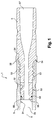
- La
figure 1 est une vue en coupe d'un système d'assemblage selon l'invention. - En référence à la
figure 1 , nous allons décrire un système d'assemblage de manche 1 selon l'invention. Le système d'assemblage de manche 1 comporte ici deux tronçons de manche 3,5. - Le premier tronçon de manche 3 est de forme générale cylindrique de révolution d'axe longitudinal X. Le premier tronçon de manche 3 est creux : il comporte un évidement 35 débouchant selon l'axe longitudinal X au niveau d'une extrémité 36. Depuis cette extrémité 36, le premier tronçon de manche 3 comprend successivement, de droite à gauche sur la
figure 1 : - Une surface d'extrémité qui est une surface d'appui 34 formant une butée d'appui du premier tronçon de manche 3 ;
- Une première partie comportant un filetage 33. Le filetage 33 est ici un filetage trapézoïdal. D'autres types de filetage peuvent être utilisés en variante de réalisation. Le filetage 33 s'étend longitudinalement sur une première longueur prédéterminée de l'évidement 35 du premier tronçon de manche 3.
- Une deuxième partie comportant une première portion 32 présentant, ici, une forme cylindrique de révolution d'axe X. Cette première portion 32 est formée d'une surface de contact latérale délimitant, au niveau de cette première portion 32, l'évidement 35 du premier tronçon de manche 3. De nouveau, cette première portion 32 s'étend longitudinalement sur une deuxième longueur prédéterminée de l'évidement 35 du premier tronçon de manche 3.
- Une troisième partie comportant une surface d'appui 31 qui s'étend longitudinalement sur une troisième longueur prédéterminée de l'évidement 35 du premier tronçon de manche 3. La surface d'appui 31 est de forme cylindrique de révolution d'axe X et délimite au niveau de la troisième partie l'évidement 35 du premier tronçon de manche 3.
- Le deuxième tronçon de manche 5 est, lui aussi, de forme générale cylindrique de révolution d'axe longitudinal X. Le deuxième tronçon de manche 5 est creux : il comporte un évidement 57 débouchant selon l'axe longitudinal X au niveau d'une extrémité 56. Depuis cette extrémité 56, le deuxième tronçon de manche 5 comprend successivement, de gauche à droite sur la
figure 1 : - Une gorge annulaire 55 réalisée sur une paroi latérale externe de l'extrémité 56 du deuxième tronçon de manche 5. La gorge annulaire 55 reçoit un joint de frottement 51. Le joint de frottement 51 s'étend, radialement de manière centrifuge, en saillie depuis la paroi latérale externe.
- Une première partie comportant une seconde portion 52 présentant, ici, une forme cylindrique de révolution d'axe X. Cette seconde portion 52 est formée d'une surface de contact latérale formant, au niveau de cette seconde portion 52, la paroi latérale du deuxième tronçon de manche 5. Cette seconde portion 52 s'étend longitudinalement sur une longueur au moins sensiblement équivalente à la deuxième longueur prédéterminée de l'évidement 35 du premier tronçon de manche 3.
- Une deuxième partie comportant un filetage 53. Le filetage 53 est ici un filetage trapézoïdal. D'autres types de filetage peuvent être utilisés en variante de réalisation. Le filetage 53 s'étend longitudinalement sur une longueur au moins sensiblement équivalente à la première longueur prédéterminée de l'évidement 35 du premier tronçon de manche 3.
- Une surface d'extrémité qui est une surface d'appui 54 formant une butée d'appui du deuxième tronçon de manche 5.
- Les filetages 33 et 53 sont complémentaires l'un de l'autre. Il en est de même des première 32 et seconde 52 portions qui présente des formes complémentaires l'une de l'autre. La première portion 32 est une portion femelle et la seconde portion 52 est une portion mâle.
- Nous allons maintenant décrire un assemblage des premier 3 et deuxième 5 tronçons de manche l'un avec l'autre.
- L'extrémité 56 du deuxième tronçon de manche 5 est introduite, selon l'axe longitudinal X, dans l'évidement 35 du premier tronçon de manche 3, puis le deuxième tronçon de manche 5 est vissé en faisant coopérer l'un avec l'autre les filetages 33 et 53, jusqu'à ce que la surface d'appui 54 du deuxième tronçon de manche 5 vienne en appui avec la surface d'appui 34 lors d'un serrage. Les deux surfaces d'appui 34,54 forment alors une butée d'appui du système d'assemblage 1 selon l'invention. Les filetages 33 et 53 forment alors des moyens de retenue du système d'assemblage 1 selon l'invention.
- Une fois le serrage du deuxième tronçon de manche 5 dans le premier tronçon de manche 3 réalisé, les première 32 et seconde 52 portions sont en contact l'une avec l'autre du fait de leur complémentarité de forme et d'un ajustement glissant ainsi réalisé entre les deux portions 32,52. Elles s'étendent en regard et en contact l'une de l'autre. Les première 32 et seconde 52 portions forment alors des moyens de reprise d'effort du système d'assemblage 1 selon l'invention. Cela permet de transmettre les efforts de flexion, en particulier, de l'un des premier 3 et deuxième 5 tronçons de manche vers l'autre des premier 3 et deuxième 5 tronçons de manche.
- D'autre part, une fois le serrage du deuxième tronçon de manche 5 dans le premier tronçon de manche 3 réalisé, le joint de frottement 51 est écrasé dans la gorge annulaire 55 par appui de la surface d'appui 31 du premier tronçon de manche 3 qui s'étend alors en regard de la gorge annulaire 55. L'écrasement du joint de frottement 51 permet une sécurisation du serrage ainsi réalisé entre les premier 3 et deuxième 5 tronçons de manche. La gorge annulaire 55, le joint de frottement 51 et la surface d'appui 31 forment des moyens de sécurisation d'un assemblage par frottement du système d'assemblage 1 selon l'invention.
- Bien entendu, il est possible d'apporter à l'invention de nombreuses modifications sans pour autant sortir du cadre de celle-ci.
Claims (9)
- Système d'assemblage de manche (1) comportant des premier (3) et deuxième (5) tronçons de manches destinés à être assemblés l'un avec l'autre, des moyens de retenue (33,53) de l'un des premier et deuxième tronçons de manche dans l'autre des premier et deuxième tronçons de manche et des moyens de sécurisation par frottement (31,51,55) d'un assemblage des premier et deuxième tronçons de manche, caractérisé en ce que les moyens de sécurisation par frottement comportent un joint de frottement (51) interposé entre les premier et deuxième tronçons de manche.
- Système d'assemblage selon la revendication 1, caractérisé en ce que l'un des premier et deuxième tronçons de manche comporte une gorge annulaire de réception (55) du joint de frottement.
- Système d'assemblage selon la revendication 2, caractérisé en ce que l'autre des premier et deuxième tronçons de manche comporte une surface d'appui (31) apte à s'étendre en regard de la gorge annulaire.
- Système d'assemblage selon l'une des revendications 1 à 3, caractérisé en ce que les moyens de retenue comprennent un filetage permettant de visser l'un des premier et deuxième tronçons de manche dans l'autre des premier et deuxième tronçons de manche.
- Système d'assemblage selon la revendication 4, caractérisé en ce que le filetage est un filetage trapézoïdal.
- Système d'assemblage selon l'une des revendications 1 à 5, caractérisé en ce qu'il comporte en outre des moyens de reprise d'effort (32,52) entre les premier et deuxième tronçons de manche.
- Système d'assemblage selon la revendication 6, caractérisé en ce que les moyens de reprise d'effort comportent une première portion (32) de l'un des premier et deuxième tronçons de manche et une seconde portion (52) de l'autre des premier et deuxième tronçons de manche, les première et seconde portions étant complémentaires de forme l'une de l'autre.
- Système d'assemblage selon la revendication 7, caractérisé en ce que les première et seconde portions sont de forme cylindrique de révolution.
- Système d'assemblage selon l'une des revendications 6 à 8, caractérisé en ce que les moyens de reprise d'effort sont placés entre les moyens de sécurisation d'un assemblage et les moyens de retenue.
Applications Claiming Priority (1)
| Application Number | Priority Date | Filing Date | Title |
|---|---|---|---|
| FR1556262A FR3038244B1 (fr) | 2015-07-02 | 2015-07-02 | Systeme d'assemblage de manche pour un outil a main |
Publications (2)
| Publication Number | Publication Date |
|---|---|
| EP3112091A1 true EP3112091A1 (fr) | 2017-01-04 |
| EP3112091B1 EP3112091B1 (fr) | 2023-01-11 |
Family
ID=54007898
Family Applications (1)
| Application Number | Title | Priority Date | Filing Date |
|---|---|---|---|
| EP16176737.1A Active EP3112091B1 (fr) | 2015-07-02 | 2016-06-28 | Systeme d'assemblage de manche pour un outil a main |
Country Status (3)
| Country | Link |
|---|---|
| US (1) | US10259114B2 (fr) |
| EP (1) | EP3112091B1 (fr) |
| FR (1) | FR3038244B1 (fr) |
Families Citing this family (5)
| Publication number | Priority date | Publication date | Assignee | Title |
|---|---|---|---|---|
| US10091948B2 (en) * | 2014-07-02 | 2018-10-09 | Wicked Tuff Gear, Llc | Light pole saw |
| US10945381B1 (en) | 2014-07-02 | 2021-03-16 | Outdoor Product Innovations, Inc. | Modular tools with detachable coupling |
| USD877579S1 (en) * | 2015-12-22 | 2020-03-10 | Fiskars Finland Oy Ab | Cutting tool for tree pruning |
| US11213940B2 (en) * | 2019-02-28 | 2022-01-04 | Unger Marketing International, Llc | Dual ended handle for an implement |
| IT201900003638U1 (it) * | 2019-10-14 | 2021-04-14 | Fimm Italia S P A | Tubo componibile perfezionato. |
Citations (5)
| Publication number | Priority date | Publication date | Assignee | Title |
|---|---|---|---|---|
| US4905548A (en) * | 1988-12-02 | 1990-03-06 | Colace Ronald J | Adjustable socket wrench extension |
| US20010047570A1 (en) * | 2000-02-01 | 2001-12-06 | Lanz Donald D. | Adjustable tool mount apparatus and specialized tool handle thereof |
| US20080276429A1 (en) * | 2007-05-10 | 2008-11-13 | Bukovitz Richard K | Quick release lock mechanisms for handle extensions |
| US20090235512A1 (en) | 2005-11-10 | 2009-09-24 | Unger Marketing International, Llc. | Locking system for connecting handles and implements |
| US20140000065A1 (en) | 2012-06-29 | 2014-01-02 | The Wooster Brush Company | Extension pole with reversible tip assembly |
Family Cites Families (10)
| Publication number | Priority date | Publication date | Assignee | Title |
|---|---|---|---|---|
| DE2235109C2 (de) * | 1972-07-18 | 1982-07-15 | Robert Bosch Gmbh, 7000 Stuttgart | Verbindung zwischen einem Bohrer und einer Spindel |
| US7028375B1 (en) * | 2004-12-22 | 2006-04-18 | Carrand Companies, Inc. | Attachment of metal and plastic parts of an implement handle |
| US7458902B2 (en) * | 2007-03-14 | 2008-12-02 | Eaton Corporation | Changeable golf grip |
| US20120073408A1 (en) * | 2008-11-10 | 2012-03-29 | Lisa Leighton | Telescoping universal gas valve key |
| CA2829972A1 (fr) * | 2012-10-15 | 2014-04-15 | Erwin Tomm | Serpilliere humide avec distributeur de liquide actionne a la main |
| US20140366327A1 (en) * | 2013-06-12 | 2014-12-18 | Ben Huang | Replaceable grip and apparatus and method therefor |
| US9102051B2 (en) * | 2013-07-19 | 2015-08-11 | Chia-Yu Chen | Retractable rod structure of hand tool |
| BE1022104B1 (nl) * | 2014-04-01 | 2016-02-16 | Waak-Bw Vzw | Reservoirsteel voor een reinigingselement zoals een borstel, aftrekker of dergelijke |
| US9649759B2 (en) * | 2014-11-26 | 2017-05-16 | German J. Ubeto | Toothbrush with an extendable handle |
| US10058991B2 (en) * | 2015-03-30 | 2018-08-28 | Breaching Technologies, Inc. | Collapsible breaching tool |
-
2015
- 2015-07-02 FR FR1556262A patent/FR3038244B1/fr active Active
-
2016
- 2016-06-28 EP EP16176737.1A patent/EP3112091B1/fr active Active
- 2016-06-30 US US15/198,774 patent/US10259114B2/en active Active
Patent Citations (5)
| Publication number | Priority date | Publication date | Assignee | Title |
|---|---|---|---|---|
| US4905548A (en) * | 1988-12-02 | 1990-03-06 | Colace Ronald J | Adjustable socket wrench extension |
| US20010047570A1 (en) * | 2000-02-01 | 2001-12-06 | Lanz Donald D. | Adjustable tool mount apparatus and specialized tool handle thereof |
| US20090235512A1 (en) | 2005-11-10 | 2009-09-24 | Unger Marketing International, Llc. | Locking system for connecting handles and implements |
| US20080276429A1 (en) * | 2007-05-10 | 2008-11-13 | Bukovitz Richard K | Quick release lock mechanisms for handle extensions |
| US20140000065A1 (en) | 2012-06-29 | 2014-01-02 | The Wooster Brush Company | Extension pole with reversible tip assembly |
Also Published As
| Publication number | Publication date |
|---|---|
| US20170001297A1 (en) | 2017-01-05 |
| EP3112091B1 (fr) | 2023-01-11 |
| US10259114B2 (en) | 2019-04-16 |
| FR3038244B1 (fr) | 2018-01-26 |
| FR3038244A1 (fr) | 2017-01-06 |
Similar Documents
| Publication | Publication Date | Title |
|---|---|---|
| EP3112091B1 (fr) | Systeme d'assemblage de manche pour un outil a main | |
| EP2787579B1 (fr) | Dispositif de fixation rapide pour connecteur en deux parties à déconnexion rapide | |
| EP3684549B1 (fr) | Douille de fixation pour l'assemblage de structures et fixation associée | |
| EP3482088A1 (fr) | Rivet de fixation aveugle avec fût épaulé et procédé d'installation associé | |
| FR2801828A1 (fr) | Outil de serrage en deux parties pouvant etre desaccouplees, destine en particulier a la chirurgie orthopedique du rachis | |
| EP0402198B1 (fr) | Ensemble d'écrou à verrouillage | |
| EP3999766B1 (fr) | Dispositif de raccordement fluidique compact et demontable | |
| FR2895467A1 (fr) | Agencement pour l'assemblage de deux pieces par vissage par l'intermediaire d'un ensemble vis-ecrou | |
| FR2626330A1 (fr) | Ecrou de fixation | |
| FR2808310A1 (fr) | Agencement de blocage axial d'une liaison entre un arbre creux et un tourillon a emmancher | |
| CH703122B1 (fr) | Outillage pour l'extraction de lunettes de montres. | |
| FR2975323A1 (fr) | Dispositif pour l'extraction de bague | |
| FR3042830A1 (fr) | Rivet auto-perceur a haute resistance mecanique avec element de percage ejectable | |
| FR3060874A1 (fr) | Cosse de raccordement a une batterie | |
| EP2372171B1 (fr) | Ensemble de fixation | |
| EP0648945B1 (fr) | Dispositif de fixation par vissage | |
| FR3016665A1 (fr) | Element a visser | |
| EP3999765B1 (fr) | Dispositif de raccordement fluidique compact et démontable | |
| EP3227571B1 (fr) | Élément de fixation avec limitation de couple | |
| FR3003192A1 (fr) | Douille ajustable | |
| FR3070136A1 (fr) | Outillage d'assemblage de deux conduits | |
| EP4123187A1 (fr) | Fixation pour l'assemblage temporaire de structures | |
| WO2002101248A1 (fr) | Dispositif de fixation provisoire | |
| FR2461536A1 (fr) | Poincon de decoupage | |
| EP1382863A1 (fr) | Vis a tête specialement adaptée à un embout de préhension et de vissage |
Legal Events
| Date | Code | Title | Description |
|---|---|---|---|
| PUAI | Public reference made under article 153(3) epc to a published international application that has entered the european phase |
Free format text: ORIGINAL CODE: 0009012 |
|
| STAA | Information on the status of an ep patent application or granted ep patent |
Free format text: STATUS: THE APPLICATION HAS BEEN PUBLISHED |
|
| AK | Designated contracting states |
Kind code of ref document: A1 Designated state(s): AL AT BE BG CH CY CZ DE DK EE ES FI FR GB GR HR HU IE IS IT LI LT LU LV MC MK MT NL NO PL PT RO RS SE SI SK SM TR |
|
| AX | Request for extension of the european patent |
Extension state: BA ME |
|
| STAA | Information on the status of an ep patent application or granted ep patent |
Free format text: STATUS: REQUEST FOR EXAMINATION WAS MADE |
|
| 17P | Request for examination filed |
Effective date: 20170126 |
|
| RBV | Designated contracting states (corrected) |
Designated state(s): AL AT BE BG CH CY CZ DE DK EE ES FI FR GB GR HR HU IE IS IT LI LT LU LV MC MK MT NL NO PL PT RO RS SE SI SK SM TR |
|
| RAP1 | Party data changed (applicant data changed or rights of an application transferred) |
Owner name: SECATEURS PRADINES |
|
| STAA | Information on the status of an ep patent application or granted ep patent |
Free format text: STATUS: EXAMINATION IS IN PROGRESS |
|
| 17Q | First examination report despatched |
Effective date: 20200917 |
|
| GRAP | Despatch of communication of intention to grant a patent |
Free format text: ORIGINAL CODE: EPIDOSNIGR1 |
|
| STAA | Information on the status of an ep patent application or granted ep patent |
Free format text: STATUS: GRANT OF PATENT IS INTENDED |
|
| INTG | Intention to grant announced |
Effective date: 20220826 |
|
| GRAS | Grant fee paid |
Free format text: ORIGINAL CODE: EPIDOSNIGR3 |
|
| GRAA | (expected) grant |
Free format text: ORIGINAL CODE: 0009210 |
|
| STAA | Information on the status of an ep patent application or granted ep patent |
Free format text: STATUS: THE PATENT HAS BEEN GRANTED |
|
| AK | Designated contracting states |
Kind code of ref document: B1 Designated state(s): AL AT BE BG CH CY CZ DE DK EE ES FI FR GB GR HR HU IE IS IT LI LT LU LV MC MK MT NL NO PL PT RO RS SE SI SK SM TR |
|
| REG | Reference to a national code |
Ref country code: GB Ref legal event code: FG4D Free format text: NOT ENGLISH |
|
| REG | Reference to a national code |
Ref country code: CH Ref legal event code: EP |
|
| REG | Reference to a national code |
Ref country code: DE Ref legal event code: R096 Ref document number: 602016077379 Country of ref document: DE |
|
| REG | Reference to a national code |
Ref country code: IE Ref legal event code: FG4D Free format text: LANGUAGE OF EP DOCUMENT: FRENCH |
|
| REG | Reference to a national code |
Ref country code: AT Ref legal event code: REF Ref document number: 1543131 Country of ref document: AT Kind code of ref document: T Effective date: 20230215 |
|
| REG | Reference to a national code |
Ref country code: LT Ref legal event code: MG9D |
|
| REG | Reference to a national code |
Ref country code: NL Ref legal event code: MP Effective date: 20230111 |
|
| REG | Reference to a national code |
Ref country code: AT Ref legal event code: MK05 Ref document number: 1543131 Country of ref document: AT Kind code of ref document: T Effective date: 20230111 |
|
| PG25 | Lapsed in a contracting state [announced via postgrant information from national office to epo] |
Ref country code: NL Free format text: LAPSE BECAUSE OF FAILURE TO SUBMIT A TRANSLATION OF THE DESCRIPTION OR TO PAY THE FEE WITHIN THE PRESCRIBED TIME-LIMIT Effective date: 20230111 |
|
| PG25 | Lapsed in a contracting state [announced via postgrant information from national office to epo] |
Ref country code: RS Free format text: LAPSE BECAUSE OF FAILURE TO SUBMIT A TRANSLATION OF THE DESCRIPTION OR TO PAY THE FEE WITHIN THE PRESCRIBED TIME-LIMIT Effective date: 20230111 Ref country code: PT Free format text: LAPSE BECAUSE OF FAILURE TO SUBMIT A TRANSLATION OF THE DESCRIPTION OR TO PAY THE FEE WITHIN THE PRESCRIBED TIME-LIMIT Effective date: 20230511 Ref country code: NO Free format text: LAPSE BECAUSE OF FAILURE TO SUBMIT A TRANSLATION OF THE DESCRIPTION OR TO PAY THE FEE WITHIN THE PRESCRIBED TIME-LIMIT Effective date: 20230411 Ref country code: LV Free format text: LAPSE BECAUSE OF FAILURE TO SUBMIT A TRANSLATION OF THE DESCRIPTION OR TO PAY THE FEE WITHIN THE PRESCRIBED TIME-LIMIT Effective date: 20230111 Ref country code: LT Free format text: LAPSE BECAUSE OF FAILURE TO SUBMIT A TRANSLATION OF THE DESCRIPTION OR TO PAY THE FEE WITHIN THE PRESCRIBED TIME-LIMIT Effective date: 20230111 Ref country code: HR Free format text: LAPSE BECAUSE OF FAILURE TO SUBMIT A TRANSLATION OF THE DESCRIPTION OR TO PAY THE FEE WITHIN THE PRESCRIBED TIME-LIMIT Effective date: 20230111 Ref country code: ES Free format text: LAPSE BECAUSE OF FAILURE TO SUBMIT A TRANSLATION OF THE DESCRIPTION OR TO PAY THE FEE WITHIN THE PRESCRIBED TIME-LIMIT Effective date: 20230111 Ref country code: AT Free format text: LAPSE BECAUSE OF FAILURE TO SUBMIT A TRANSLATION OF THE DESCRIPTION OR TO PAY THE FEE WITHIN THE PRESCRIBED TIME-LIMIT Effective date: 20230111 |
|
| PG25 | Lapsed in a contracting state [announced via postgrant information from national office to epo] |
Ref country code: SE Free format text: LAPSE BECAUSE OF FAILURE TO SUBMIT A TRANSLATION OF THE DESCRIPTION OR TO PAY THE FEE WITHIN THE PRESCRIBED TIME-LIMIT Effective date: 20230111 Ref country code: PL Free format text: LAPSE BECAUSE OF FAILURE TO SUBMIT A TRANSLATION OF THE DESCRIPTION OR TO PAY THE FEE WITHIN THE PRESCRIBED TIME-LIMIT Effective date: 20230111 Ref country code: IS Free format text: LAPSE BECAUSE OF FAILURE TO SUBMIT A TRANSLATION OF THE DESCRIPTION OR TO PAY THE FEE WITHIN THE PRESCRIBED TIME-LIMIT Effective date: 20230511 Ref country code: GR Free format text: LAPSE BECAUSE OF FAILURE TO SUBMIT A TRANSLATION OF THE DESCRIPTION OR TO PAY THE FEE WITHIN THE PRESCRIBED TIME-LIMIT Effective date: 20230412 Ref country code: FI Free format text: LAPSE BECAUSE OF FAILURE TO SUBMIT A TRANSLATION OF THE DESCRIPTION OR TO PAY THE FEE WITHIN THE PRESCRIBED TIME-LIMIT Effective date: 20230111 |
|
| REG | Reference to a national code |
Ref country code: DE Ref legal event code: R097 Ref document number: 602016077379 Country of ref document: DE |
|
| PG25 | Lapsed in a contracting state [announced via postgrant information from national office to epo] |
Ref country code: SM Free format text: LAPSE BECAUSE OF FAILURE TO SUBMIT A TRANSLATION OF THE DESCRIPTION OR TO PAY THE FEE WITHIN THE PRESCRIBED TIME-LIMIT Effective date: 20230111 Ref country code: RO Free format text: LAPSE BECAUSE OF FAILURE TO SUBMIT A TRANSLATION OF THE DESCRIPTION OR TO PAY THE FEE WITHIN THE PRESCRIBED TIME-LIMIT Effective date: 20230111 Ref country code: EE Free format text: LAPSE BECAUSE OF FAILURE TO SUBMIT A TRANSLATION OF THE DESCRIPTION OR TO PAY THE FEE WITHIN THE PRESCRIBED TIME-LIMIT Effective date: 20230111 Ref country code: DK Free format text: LAPSE BECAUSE OF FAILURE TO SUBMIT A TRANSLATION OF THE DESCRIPTION OR TO PAY THE FEE WITHIN THE PRESCRIBED TIME-LIMIT Effective date: 20230111 Ref country code: CZ Free format text: LAPSE BECAUSE OF FAILURE TO SUBMIT A TRANSLATION OF THE DESCRIPTION OR TO PAY THE FEE WITHIN THE PRESCRIBED TIME-LIMIT Effective date: 20230111 |
|
| PLBE | No opposition filed within time limit |
Free format text: ORIGINAL CODE: 0009261 |
|
| STAA | Information on the status of an ep patent application or granted ep patent |
Free format text: STATUS: NO OPPOSITION FILED WITHIN TIME LIMIT |
|
| PG25 | Lapsed in a contracting state [announced via postgrant information from national office to epo] |
Ref country code: SK Free format text: LAPSE BECAUSE OF FAILURE TO SUBMIT A TRANSLATION OF THE DESCRIPTION OR TO PAY THE FEE WITHIN THE PRESCRIBED TIME-LIMIT Effective date: 20230111 |
|
| 26N | No opposition filed |
Effective date: 20231012 |
|
| REG | Reference to a national code |
Ref country code: DE Ref legal event code: R119 Ref document number: 602016077379 Country of ref document: DE |
|
| PG25 | Lapsed in a contracting state [announced via postgrant information from national office to epo] |
Ref country code: MC Free format text: LAPSE BECAUSE OF FAILURE TO SUBMIT A TRANSLATION OF THE DESCRIPTION OR TO PAY THE FEE WITHIN THE PRESCRIBED TIME-LIMIT Effective date: 20230111 |
|
| PG25 | Lapsed in a contracting state [announced via postgrant information from national office to epo] |
Ref country code: SI Free format text: LAPSE BECAUSE OF FAILURE TO SUBMIT A TRANSLATION OF THE DESCRIPTION OR TO PAY THE FEE WITHIN THE PRESCRIBED TIME-LIMIT Effective date: 20230111 Ref country code: MC Free format text: LAPSE BECAUSE OF FAILURE TO SUBMIT A TRANSLATION OF THE DESCRIPTION OR TO PAY THE FEE WITHIN THE PRESCRIBED TIME-LIMIT Effective date: 20230111 |
|
| REG | Reference to a national code |
Ref country code: CH Ref legal event code: PL |
|
| REG | Reference to a national code |
Ref country code: BE Ref legal event code: MM Effective date: 20230630 |
|
| GBPC | Gb: european patent ceased through non-payment of renewal fee |
Effective date: 20230628 |
|
| PG25 | Lapsed in a contracting state [announced via postgrant information from national office to epo] |
Ref country code: LU Free format text: LAPSE BECAUSE OF NON-PAYMENT OF DUE FEES Effective date: 20230628 |
|
| REG | Reference to a national code |
Ref country code: IE Ref legal event code: MM4A |
|
| PG25 | Lapsed in a contracting state [announced via postgrant information from national office to epo] |
Ref country code: LU Free format text: LAPSE BECAUSE OF NON-PAYMENT OF DUE FEES Effective date: 20230628 |
|
| PG25 | Lapsed in a contracting state [announced via postgrant information from national office to epo] |
Ref country code: IE Free format text: LAPSE BECAUSE OF NON-PAYMENT OF DUE FEES Effective date: 20230628 |
|
| PG25 | Lapsed in a contracting state [announced via postgrant information from national office to epo] |
Ref country code: IE Free format text: LAPSE BECAUSE OF NON-PAYMENT OF DUE FEES Effective date: 20230628 Ref country code: DE Free format text: LAPSE BECAUSE OF NON-PAYMENT OF DUE FEES Effective date: 20240103 Ref country code: GB Free format text: LAPSE BECAUSE OF NON-PAYMENT OF DUE FEES Effective date: 20230628 Ref country code: CH Free format text: LAPSE BECAUSE OF NON-PAYMENT OF DUE FEES Effective date: 20230630 |
|
| PG25 | Lapsed in a contracting state [announced via postgrant information from national office to epo] |
Ref country code: IT Free format text: LAPSE BECAUSE OF FAILURE TO SUBMIT A TRANSLATION OF THE DESCRIPTION OR TO PAY THE FEE WITHIN THE PRESCRIBED TIME-LIMIT Effective date: 20230111 Ref country code: BE Free format text: LAPSE BECAUSE OF NON-PAYMENT OF DUE FEES Effective date: 20230630 |
|
| PG25 | Lapsed in a contracting state [announced via postgrant information from national office to epo] |
Ref country code: BG Free format text: LAPSE BECAUSE OF FAILURE TO SUBMIT A TRANSLATION OF THE DESCRIPTION OR TO PAY THE FEE WITHIN THE PRESCRIBED TIME-LIMIT Effective date: 20230111 |
|
| PG25 | Lapsed in a contracting state [announced via postgrant information from national office to epo] |
Ref country code: BG Free format text: LAPSE BECAUSE OF FAILURE TO SUBMIT A TRANSLATION OF THE DESCRIPTION OR TO PAY THE FEE WITHIN THE PRESCRIBED TIME-LIMIT Effective date: 20230111 |
|
| PGFP | Annual fee paid to national office [announced via postgrant information from national office to epo] |
Ref country code: FR Payment date: 20250613 Year of fee payment: 10 |
|
| PG25 | Lapsed in a contracting state [announced via postgrant information from national office to epo] |
Ref country code: CY Free format text: LAPSE BECAUSE OF FAILURE TO SUBMIT A TRANSLATION OF THE DESCRIPTION OR TO PAY THE FEE WITHIN THE PRESCRIBED TIME-LIMIT; INVALID AB INITIO Effective date: 20160628 |
|
| PG25 | Lapsed in a contracting state [announced via postgrant information from national office to epo] |
Ref country code: HU Free format text: LAPSE BECAUSE OF FAILURE TO SUBMIT A TRANSLATION OF THE DESCRIPTION OR TO PAY THE FEE WITHIN THE PRESCRIBED TIME-LIMIT; INVALID AB INITIO Effective date: 20160628 |
|
| PG25 | Lapsed in a contracting state [announced via postgrant information from national office to epo] |
Ref country code: TR Free format text: LAPSE BECAUSE OF FAILURE TO SUBMIT A TRANSLATION OF THE DESCRIPTION OR TO PAY THE FEE WITHIN THE PRESCRIBED TIME-LIMIT Effective date: 20230111 |