EP3112202B1 - Kupplungssteuerungsvorrichtung für fahrzeug mit allradantrieb - Google Patents
Kupplungssteuerungsvorrichtung für fahrzeug mit allradantrieb Download PDFInfo
- Publication number
- EP3112202B1 EP3112202B1 EP15755688.7A EP15755688A EP3112202B1 EP 3112202 B1 EP3112202 B1 EP 3112202B1 EP 15755688 A EP15755688 A EP 15755688A EP 3112202 B1 EP3112202 B1 EP 3112202B1
- Authority
- EP
- European Patent Office
- Prior art keywords
- wheel drive
- clutch
- dog clutch
- vehicle
- drive
- Prior art date
- Legal status (The legal status is an assumption and is not a legal conclusion. Google has not performed a legal analysis and makes no representation as to the accuracy of the status listed.)
- Active
Links
Images





Classifications
-
- B—PERFORMING OPERATIONS; TRANSPORTING
- B60—VEHICLES IN GENERAL
- B60K—ARRANGEMENT OR MOUNTING OF PROPULSION UNITS OR OF TRANSMISSIONS IN VEHICLES; ARRANGEMENT OR MOUNTING OF PLURAL DIVERSE PRIME-MOVERS IN VEHICLES; AUXILIARY DRIVES FOR VEHICLES; INSTRUMENTATION OR DASHBOARDS FOR VEHICLES; ARRANGEMENTS IN CONNECTION WITH COOLING, AIR INTAKE, GAS EXHAUST OR FUEL SUPPLY OF PROPULSION UNITS IN VEHICLES
- B60K23/00—Arrangement or mounting of control devices for vehicle transmissions, or parts thereof, not otherwise provided for
- B60K23/08—Arrangement or mounting of control devices for vehicle transmissions, or parts thereof, not otherwise provided for for changing number of driven wheels, for switching from driving one axle to driving two or more axles
-
- B—PERFORMING OPERATIONS; TRANSPORTING
- B60—VEHICLES IN GENERAL
- B60K—ARRANGEMENT OR MOUNTING OF PROPULSION UNITS OR OF TRANSMISSIONS IN VEHICLES; ARRANGEMENT OR MOUNTING OF PLURAL DIVERSE PRIME-MOVERS IN VEHICLES; AUXILIARY DRIVES FOR VEHICLES; INSTRUMENTATION OR DASHBOARDS FOR VEHICLES; ARRANGEMENTS IN CONNECTION WITH COOLING, AIR INTAKE, GAS EXHAUST OR FUEL SUPPLY OF PROPULSION UNITS IN VEHICLES
- B60K17/00—Arrangement or mounting of transmissions in vehicles
- B60K17/02—Arrangement or mounting of transmissions in vehicles characterised by arrangement, location, or kind of clutch
-
- B—PERFORMING OPERATIONS; TRANSPORTING
- B60—VEHICLES IN GENERAL
- B60K—ARRANGEMENT OR MOUNTING OF PROPULSION UNITS OR OF TRANSMISSIONS IN VEHICLES; ARRANGEMENT OR MOUNTING OF PLURAL DIVERSE PRIME-MOVERS IN VEHICLES; AUXILIARY DRIVES FOR VEHICLES; INSTRUMENTATION OR DASHBOARDS FOR VEHICLES; ARRANGEMENTS IN CONNECTION WITH COOLING, AIR INTAKE, GAS EXHAUST OR FUEL SUPPLY OF PROPULSION UNITS IN VEHICLES
- B60K17/00—Arrangement or mounting of transmissions in vehicles
- B60K17/34—Arrangement or mounting of transmissions in vehicles for driving both front and rear wheels, e.g. four wheel drive vehicles
- B60K17/344—Arrangement or mounting of transmissions in vehicles for driving both front and rear wheels, e.g. four wheel drive vehicles having a transfer gear
-
- F—MECHANICAL ENGINEERING; LIGHTING; HEATING; WEAPONS; BLASTING
- F16—ENGINEERING ELEMENTS AND UNITS; GENERAL MEASURES FOR PRODUCING AND MAINTAINING EFFECTIVE FUNCTIONING OF MACHINES OR INSTALLATIONS; THERMAL INSULATION IN GENERAL
- F16D—COUPLINGS FOR TRANSMITTING ROTATION; CLUTCHES; BRAKES
- F16D11/00—Clutches in which the members have interengaging parts
-
- F—MECHANICAL ENGINEERING; LIGHTING; HEATING; WEAPONS; BLASTING
- F16—ENGINEERING ELEMENTS AND UNITS; GENERAL MEASURES FOR PRODUCING AND MAINTAINING EFFECTIVE FUNCTIONING OF MACHINES OR INSTALLATIONS; THERMAL INSULATION IN GENERAL
- F16D—COUPLINGS FOR TRANSMITTING ROTATION; CLUTCHES; BRAKES
- F16D13/00—Friction clutches
-
- F—MECHANICAL ENGINEERING; LIGHTING; HEATING; WEAPONS; BLASTING
- F16—ENGINEERING ELEMENTS AND UNITS; GENERAL MEASURES FOR PRODUCING AND MAINTAINING EFFECTIVE FUNCTIONING OF MACHINES OR INSTALLATIONS; THERMAL INSULATION IN GENERAL
- F16D—COUPLINGS FOR TRANSMITTING ROTATION; CLUTCHES; BRAKES
- F16D21/00—Systems comprising a plurality of actuated clutches
-
- F—MECHANICAL ENGINEERING; LIGHTING; HEATING; WEAPONS; BLASTING
- F16—ENGINEERING ELEMENTS AND UNITS; GENERAL MEASURES FOR PRODUCING AND MAINTAINING EFFECTIVE FUNCTIONING OF MACHINES OR INSTALLATIONS; THERMAL INSULATION IN GENERAL
- F16D—COUPLINGS FOR TRANSMITTING ROTATION; CLUTCHES; BRAKES
- F16D48/00—External control of clutches
- F16D48/06—Control by electric or electronic means, e.g. of fluid pressure
-
- B—PERFORMING OPERATIONS; TRANSPORTING
- B60—VEHICLES IN GENERAL
- B60K—ARRANGEMENT OR MOUNTING OF PROPULSION UNITS OR OF TRANSMISSIONS IN VEHICLES; ARRANGEMENT OR MOUNTING OF PLURAL DIVERSE PRIME-MOVERS IN VEHICLES; AUXILIARY DRIVES FOR VEHICLES; INSTRUMENTATION OR DASHBOARDS FOR VEHICLES; ARRANGEMENTS IN CONNECTION WITH COOLING, AIR INTAKE, GAS EXHAUST OR FUEL SUPPLY OF PROPULSION UNITS IN VEHICLES
- B60K23/00—Arrangement or mounting of control devices for vehicle transmissions, or parts thereof, not otherwise provided for
- B60K23/08—Arrangement or mounting of control devices for vehicle transmissions, or parts thereof, not otherwise provided for for changing number of driven wheels, for switching from driving one axle to driving two or more axles
- B60K23/0808—Arrangement or mounting of control devices for vehicle transmissions, or parts thereof, not otherwise provided for for changing number of driven wheels, for switching from driving one axle to driving two or more axles for varying torque distribution between driven axles, e.g. by transfer clutch
- B60K2023/0816—Arrangement or mounting of control devices for vehicle transmissions, or parts thereof, not otherwise provided for for changing number of driven wheels, for switching from driving one axle to driving two or more axles for varying torque distribution between driven axles, e.g. by transfer clutch for varying front-rear torque distribution with a central differential
- B60K2023/0825—Arrangement or mounting of control devices for vehicle transmissions, or parts thereof, not otherwise provided for for changing number of driven wheels, for switching from driving one axle to driving two or more axles for varying torque distribution between driven axles, e.g. by transfer clutch for varying front-rear torque distribution with a central differential for adding torque to the front wheels
-
- B—PERFORMING OPERATIONS; TRANSPORTING
- B60—VEHICLES IN GENERAL
- B60K—ARRANGEMENT OR MOUNTING OF PROPULSION UNITS OR OF TRANSMISSIONS IN VEHICLES; ARRANGEMENT OR MOUNTING OF PLURAL DIVERSE PRIME-MOVERS IN VEHICLES; AUXILIARY DRIVES FOR VEHICLES; INSTRUMENTATION OR DASHBOARDS FOR VEHICLES; ARRANGEMENTS IN CONNECTION WITH COOLING, AIR INTAKE, GAS EXHAUST OR FUEL SUPPLY OF PROPULSION UNITS IN VEHICLES
- B60K23/00—Arrangement or mounting of control devices for vehicle transmissions, or parts thereof, not otherwise provided for
- B60K23/08—Arrangement or mounting of control devices for vehicle transmissions, or parts thereof, not otherwise provided for for changing number of driven wheels, for switching from driving one axle to driving two or more axles
- B60K23/0808—Arrangement or mounting of control devices for vehicle transmissions, or parts thereof, not otherwise provided for for changing number of driven wheels, for switching from driving one axle to driving two or more axles for varying torque distribution between driven axles, e.g. by transfer clutch
- B60K2023/0816—Arrangement or mounting of control devices for vehicle transmissions, or parts thereof, not otherwise provided for for changing number of driven wheels, for switching from driving one axle to driving two or more axles for varying torque distribution between driven axles, e.g. by transfer clutch for varying front-rear torque distribution with a central differential
- B60K2023/0833—Arrangement or mounting of control devices for vehicle transmissions, or parts thereof, not otherwise provided for for changing number of driven wheels, for switching from driving one axle to driving two or more axles for varying torque distribution between driven axles, e.g. by transfer clutch for varying front-rear torque distribution with a central differential for adding torque to the rear wheels
-
- B—PERFORMING OPERATIONS; TRANSPORTING
- B60—VEHICLES IN GENERAL
- B60K—ARRANGEMENT OR MOUNTING OF PROPULSION UNITS OR OF TRANSMISSIONS IN VEHICLES; ARRANGEMENT OR MOUNTING OF PLURAL DIVERSE PRIME-MOVERS IN VEHICLES; AUXILIARY DRIVES FOR VEHICLES; INSTRUMENTATION OR DASHBOARDS FOR VEHICLES; ARRANGEMENTS IN CONNECTION WITH COOLING, AIR INTAKE, GAS EXHAUST OR FUEL SUPPLY OF PROPULSION UNITS IN VEHICLES
- B60K23/00—Arrangement or mounting of control devices for vehicle transmissions, or parts thereof, not otherwise provided for
- B60K23/08—Arrangement or mounting of control devices for vehicle transmissions, or parts thereof, not otherwise provided for for changing number of driven wheels, for switching from driving one axle to driving two or more axles
- B60K2023/085—Arrangement or mounting of control devices for vehicle transmissions, or parts thereof, not otherwise provided for for changing number of driven wheels, for switching from driving one axle to driving two or more axles automatically actuated
- B60K2023/0858—Arrangement or mounting of control devices for vehicle transmissions, or parts thereof, not otherwise provided for for changing number of driven wheels, for switching from driving one axle to driving two or more axles automatically actuated with electric means, e.g. electro-hydraulic means
-
- F—MECHANICAL ENGINEERING; LIGHTING; HEATING; WEAPONS; BLASTING
- F16—ENGINEERING ELEMENTS AND UNITS; GENERAL MEASURES FOR PRODUCING AND MAINTAINING EFFECTIVE FUNCTIONING OF MACHINES OR INSTALLATIONS; THERMAL INSULATION IN GENERAL
- F16D—COUPLINGS FOR TRANSMITTING ROTATION; CLUTCHES; BRAKES
- F16D2500/00—External control of clutches by electric or electronic means
- F16D2500/10—System to be controlled
- F16D2500/104—Clutch
- F16D2500/10406—Clutch position
- F16D2500/10431—4WD Clutch dividing power between the front and the rear axle
-
- F—MECHANICAL ENGINEERING; LIGHTING; HEATING; WEAPONS; BLASTING
- F16—ENGINEERING ELEMENTS AND UNITS; GENERAL MEASURES FOR PRODUCING AND MAINTAINING EFFECTIVE FUNCTIONING OF MACHINES OR INSTALLATIONS; THERMAL INSULATION IN GENERAL
- F16D—COUPLINGS FOR TRANSMITTING ROTATION; CLUTCHES; BRAKES
- F16D2500/00—External control of clutches by electric or electronic means
- F16D2500/10—System to be controlled
- F16D2500/104—Clutch
- F16D2500/10443—Clutch type
- F16D2500/1045—Friction clutch
-
- F—MECHANICAL ENGINEERING; LIGHTING; HEATING; WEAPONS; BLASTING
- F16—ENGINEERING ELEMENTS AND UNITS; GENERAL MEASURES FOR PRODUCING AND MAINTAINING EFFECTIVE FUNCTIONING OF MACHINES OR INSTALLATIONS; THERMAL INSULATION IN GENERAL
- F16D—COUPLINGS FOR TRANSMITTING ROTATION; CLUTCHES; BRAKES
- F16D2500/00—External control of clutches by electric or electronic means
- F16D2500/10—System to be controlled
- F16D2500/104—Clutch
- F16D2500/10443—Clutch type
- F16D2500/10462—Dog-type clutch
-
- F—MECHANICAL ENGINEERING; LIGHTING; HEATING; WEAPONS; BLASTING
- F16—ENGINEERING ELEMENTS AND UNITS; GENERAL MEASURES FOR PRODUCING AND MAINTAINING EFFECTIVE FUNCTIONING OF MACHINES OR INSTALLATIONS; THERMAL INSULATION IN GENERAL
- F16D—COUPLINGS FOR TRANSMITTING ROTATION; CLUTCHES; BRAKES
- F16D2500/00—External control of clutches by electric or electronic means
- F16D2500/30—Signal inputs
- F16D2500/31—Signal inputs from the vehicle
- F16D2500/3108—Vehicle speed
-
- F—MECHANICAL ENGINEERING; LIGHTING; HEATING; WEAPONS; BLASTING
- F16—ENGINEERING ELEMENTS AND UNITS; GENERAL MEASURES FOR PRODUCING AND MAINTAINING EFFECTIVE FUNCTIONING OF MACHINES OR INSTALLATIONS; THERMAL INSULATION IN GENERAL
- F16D—COUPLINGS FOR TRANSMITTING ROTATION; CLUTCHES; BRAKES
- F16D2500/00—External control of clutches by electric or electronic means
- F16D2500/30—Signal inputs
- F16D2500/314—Signal inputs from the user
- F16D2500/31406—Signal inputs from the user input from pedals
- F16D2500/3144—Accelerator pedal position
-
- F—MECHANICAL ENGINEERING; LIGHTING; HEATING; WEAPONS; BLASTING
- F16—ENGINEERING ELEMENTS AND UNITS; GENERAL MEASURES FOR PRODUCING AND MAINTAINING EFFECTIVE FUNCTIONING OF MACHINES OR INSTALLATIONS; THERMAL INSULATION IN GENERAL
- F16D—COUPLINGS FOR TRANSMITTING ROTATION; CLUTCHES; BRAKES
- F16D2500/00—External control of clutches by electric or electronic means
- F16D2500/50—Problem to be solved by the control system
- F16D2500/512—Relating to the driver
- F16D2500/5122—Improve passengers comfort
Definitions
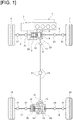
- Figure 1 illustrates the configuration of the drive system of a front wheel drive based four-wheel drive vehicle to which is applied the clutch control device of the first embodiment.
- the drive system configuration of the four-wheel drive vehicle will be described below based on Figure 1 .
- the front wheel drive system of the four-wheel drive vehicle is provided with a transverse engine 1 (drive source), a transmission 2, a front differential 3, a left front wheel drive shaft 4, a right front wheel drive shaft 5, a left front wheel 6 (main drive wheel), and a right front wheel 7 (main drive wheel), as illustrated in Figure 1 . That is, the drive force is transmitted from the transverse engine 1 and the transmission 2 to the left and right front wheel drive shafts 4, 5 via the front differential 3, and constantly drives the left and right front wheels 6, 7 while allowing a differential rotation.
- the dog clutch 8 is a dog clutch that is provided at a drive branch position from the left and right front wheels 6, 7 to the left and right rear wheels 19, 20, and that separates the system for transmitting drive force to the left and right rear wheels 19, 20 from the system for transmitting drive force to the left and right front wheels 6, 7 by releasing the clutch.
- the dog clutch 8 is disposed in a position upstream of the bevel gear 9 and the output pinion 10, configuring a transfer mechanism, provided at a drive branch position to the left and right rear wheels 19, 20.
- the electronically controlled coupling 16 is a friction clutch that is provided in a downstream position of the dog clutch 8, and that allocates a portion of the drive force from the transverse engine 1 to the left and right rear wheels 19, 20, in accordance with the clutch engagement capacity.
- This electronically controlled coupling 16 is configured to be disposed in the position of the left rear wheel drive shaft 17, which extends to the left rear wheel 19, downstream of the bevel gear 9 and the output pinion 10, which configure the transfer mechanism, via the propeller shaft 12 and the rear differential 15.
- An input side clutch plate of the electronically controlled coupling 16 is connected to a left side gear of the rear differential 15, and an output side clutch plate is connected to a left rear wheel drive shaft 17.
- the control system of the four-wheel drive vehicle is provided with an engine control module 31, a transmission control module 32, an ABS actuator control unit 33, and a 4WD control unit 34, as illustrated in Figure 2 .
- Each of the control modules and each of the control units 31-34 are configured by an arithmetic processing unit, such as a computer.
- the engine control module 31 is a control device of the transverse engine 1, which inputs detection signals from an engine rotational frequency sensor 35, an accelerator position opening amount sensor 36, and the like, as vehicle state detection devices.
- Engine rotational frequency information and accelerator position opening amount information (ACC information) are input from this engine control module 31 to the 4WD control unit 34 via a CAN communication line 37.
- the transmission control module 32 is a control device of the transmission 2, which inputs detection signals from a transmission input rotational frequency sensor 38, the transmission output rotational frequency sensor 39, and the like, as vehicle state detection devices.
- Gear ratio information is input from this transmission control module 32 to the 4WD control unit 34 via the CAN communication line 37.
- the ABS actuator control unit 33 is a control device of an ABS actuator which controls the brake fluid pressure of each wheel, which inputs detection signals from a yaw rate sensor 40, a lateral G sensor 41, a longitudinal G sensor 42, wheel speed sensors 43, 44, 45, 46, and the like, as vehicle state detection devices. Yaw rate information, lateral G information, longitudinal G information, and wheel speed information of each wheel, are input from this ABS actuator control unit 33 to the 4WD control unit 34 via the CAN communication line 37. Besides the information described above, steering angle information from a steering angle sensor 47 is input to the 4WD control unit 34 via the CAN communication line 37.
- the 4WD control unit (clutch control unit) 34 is an engagement and disengagement control device of the dog clutch 8 and the electronically controlled coupling 16, and carries out a calculation step based on various input information from each of the sensors as vehicle state detection devices.
- the control unit outputs drive control commands to a dog clutch actuator 48 (solenoid) and an electronically controlled coupling actuator 49 (electric motor).
- a dog clutch actuator 48 solenoid
- an electronically controlled coupling actuator 49 electric motor.
- a drive mode selection switch 50 a brake switch 51 that detects the presence/absence of a brake operation
- a ring gear rotational frequency sensor 52 a dog clutch stroke sensor 53
- a motor rotation angle sensor 54 a shift position switch 55, and the like are provided as sources of input information.
- auto mode there is a choice between an “eco-auto mode” and a “sports auto mode,” where the standby two-wheel drive mode, in which the dog clutch 8 is engaged and the electronically controlled coupling 16 is released, will differ depending on the selected mode. That is, when “eco-auto mode” is selected, the electronically controlled coupling 16 is put in a fully released state and waits, and when the "sports auto mode” is selected, the electronically controlled coupling 16 is put in a released state immediately before engagement and waits.
- the ring gear rotational frequency sensor 52 is a sensor for acquiring output rotational frequency information of the dog clutch 8 and which calculates the output rotational frequency of the dog clutch 8 by taking into consideration the rear side gear ratio and the front side gear ratio upon calculation with respect to the detected value of the ring gear rotational frequency.
- the input rotational frequency information of the dog clutch 8 is obtained by calculating the average value of the left and right front wheel speeds.
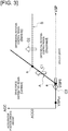
- Figure 3 illustrates a drive mode switching map corresponding to the vehicle speed VSP and the accelerator position opening amount ACC used in the clutch control when "auto mode" is selected
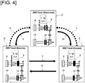
- Figure 4 illustrates the switching transition of the drive mode (disconnected two-wheel drive mode/standby two-wheel drive mode/connected four-wheel drive mode).
- the drive mode switching configuration will be described below, based on Figure 3 and Figure 4 .
- the drive mode switching map is set to be separated into a differential rotation control region (Disconnect), which is a control region for the disconnected two-wheel drive mode, a differential rotation control region (Standby), which is a control region for the standby two-wheel drive mode, and a drive force distribution region (Connect), which is a control region for the connected four-wheel drive mode, in accordance with the vehicle speed VSP and the accelerator position opening amount ACC, as illustrated in Figure 3 .
- a differential rotation control region which is a control region for the disconnected two-wheel drive mode
- Standby differential rotation control region
- Connect drive force distribution region
- region dividing line A in which the accelerator position opening amount ACC is increased proportionally with the increase in the vehicle speed VSP from a base point a of a set vehicle speed VSP0 at which the accelerator position opening amount is zero, and a region dividing line B of a constant accelerator position opening amount ACC0, which is drawn from an intersection b with the region dividing line A toward the high vehicle speed side.
- the differential rotation control region (Disconnect) which is a control region for the disconnected two-wheel drive mode, is set in the region in which the accelerator position opening amount ACC is less than or equal to the set opening amount ACC0, and which is surrounded by the vehicle speed axis line on which the accelerator position opening amount ACC is zero, the region dividing line A, and the region dividing line B. That is, the mode is set in a region in which the frequency of occurrence of differential rotation of the left and right front wheels 6, 7 and the left and right rear wheels 19, 20 due to wheel slip is extremely low, since the accelerator position opening amount ACC is less than or equal to the set accelerator position opening amount ACC0, and even if wheel slip occurs, the four-wheel drive requirement is low so that the slip increases slowly.
- the differential rotation control region which is a control region for the standby two-wheel drive mode, is set in the region in which the accelerator position opening amount ACC exceeds the set accelerator position opening amount ACC0, and which is surrounded by the region dividing line A and the region dividing line B. That is, the region is set in a region in which, since the accelerator position opening amount ACC exceeds the set accelerator position opening amount ACC0 but the vehicle speed VSP is in a high vehicle speed region, while the 4WD requirement is low, if differential rotation of the left and right front wheels 6, 7 and the left and right rear wheels 19, 20 is generated due to wheel slip, there is a high probability that slip will increase rapidly.
- the drive force distribution region (Connect) which is a control region for the connected four-wheel drive mode, is set in the region surrounded by the accelerator position opening amount axis line on which the vehicle speed VSP is zero, the vehicle speed axis line on which the accelerator position opening amount ACC is zero, and the region dividing line A. That is, the mode is set in a region in which the 4WD requirement is high, such as when starting or during high-load travel in which the vehicle speed VSP is low but the accelerator position opening amount ACC is high.
- the travel mode becomes 2WD travel (Disconnect), in which both the dog clutch 8 and the electronically controlled coupling 16 are released, as illustrated in frame C of Figure 4 .
- a front wheel drive 2WD travel in which drive force is transmitted only to the left and right front wheels 6, 7, is maintained.
- the electronically controlled coupling 16 is frictionally engaged.
- differential rotation control to suppress wheel slip is carried out by engaging the dog clutch 8 and allocating drive force to the left and right rear wheels 19, 20.
- the travel mode becomes 4WD travel (Connect) in which both the dog clutch 8 and the electronically controlled coupling 16 are engaged, as illustrated in frame E of Figure 4 .
- a drive force distribution control is carried out which achieves the optimum drive force distribution to the left and right front wheels 6, 7, and to the left and right rear wheels 19, 20 that is suited to the road conditions (for example, distribution control to the front and rear wheels at the time of starting).
- the switching transition speed of 2WD travel (Standby) ⁇ 4WD travel (Connect) (arrow J in Figure 4 ) is configured to be the same fast speed as the switching transition speed of 4WD travel (Connect) ⁇ 2WD travel (Standby) (arrow K in Figure 4 ).
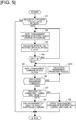
- FIG 5 illustrates the flow of process when engaging the dog clutch 8, of the clutch control process that is executed in the 4WD control unit 34. That is, the clutch control process when transitioning to the drive force distribution region (Connect) and when transitioning to the differential rotation control region (Standby), from the differential rotation control region (Disconnect), in which the vehicle state is controlled to the disconnected, two-wheel drive mode, in the drive mode map of Figure 3 , will be described. These clutch control process is repeated at a predetermined cycle of about 10-30 ms.
- Step S4 it determined whether or not the differential rotation speed ⁇ N that is calculated in Step S3 has become less than or equal to a synchronization determination threshold value ⁇ which is set in advance, that is, whether or not the dog clutch 8 has been placed in a synchronized state. Then, if ⁇ N ⁇ ⁇ (dog clutch synchronized), the process proceeds to Step S5, and if ⁇ N > ⁇ (dog clutch not synchronized), the process returns to Step S2.
- Step S6 whether or not the engagement of the dog clutch 8 has been completed is determined. Then, if the engagement has been completed, the process proceeds to Step S7, and if the engagement is incomplete, the process returns to Step S5 after executing a dog clutch engagement promotion step of Step S10.
- the engagement is determined to be completed when it is detected that the movable member makes a stroke that exceeds a set amount based on a detection of the dog clutch stroke sensor 53.
- the dog clutch engagement promotion step of Step S10 will be described further below.
- Step S103 to which the process proceeds when an acceleration state is determined in Step S102, a step to reduce the transmission torque of the electronically controlled coupling 16 is carried out and the process returns to Step S5.
- Step S105 to which the process proceeds when the vehicle is in a deceleration state, it is determined whether or not the vehicle speed VSP has been reduced to less than or equal to a vehicle speed threshold value VSPst that is set in advance; if VSP ⁇ VSPst, the process proceeds to Step S106, and if VSP > VSPst, the process returns to Step S5.
- the vehicle speed threshold value VSPst is a vehicle speed at which it is possible to contain the engagement shock that is generated when the dog clutch 8 is engaged in a non-synchronized state within a desired range, and the value is set to a vehicle speed in the vicinity of speeds immediately preceding stopping.
- Step S10 the transmission torque of the electronically controlled coupling 16 is reduced in Step S103 or S106. Accordingly, the distribution of drive force to the left and right rear wheels 19, 20 is reduced, and a differential rotation ⁇ N occurs between the input and output side meshing members 8a, 8b of the dog clutch 8.
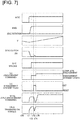
- the two time charts illustrate the operation of engagement of the dog clutch 8 in order to switch from the disconnected two-wheel drive mode to the standby two-wheel drive mode or the connected four-wheel drive mode.
- Figure 7 illustrates an example of operation during acceleration
- Figure 8 illustrates an example of operation during deceleration.
- Step S102-S103 a step to reduce the transmission torque of the electronically controlled coupling 16 is executed immediately in accordance with the setting of this engagement standby flag (Step S102-S103), which is accompanied by an occurrence of differential rotation ⁇ N between the two meshing members 8a, 8b of the dog clutch 8.
- the invention is applied to a front wheel drive based four-wheel drive vehicle (4WD engine vehicle), in which an engine is mounted as the drive source.
- the clutch control device of the present invention is applied to a rear wheel drive based four-wheel drive vehicle (4WD engine vehicle), in which the left and right rear wheels are the main drive wheels.
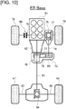
- the clutch control device may be applied to a rear wheel drive based four-wheel drive vehicle in which the positional relationship of the dog clutch and the friction clutch has the same relationship as in the first embodiment.
- the clutch control device may be applied to a front wheel drive based four-wheel drive vehicle in which the positional relationship of the dog clutch and the friction clutch has the same relationship as in the second embodiment.
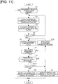
- the two-wheel drive mode is separated into the disconnected two-wheel drive mode and the standby two-wheel drive mode; however, the two-wheel drive mode may be only the disconnected two-wheel drive mode, as illustrated in Figure 12 , in order to further secure fuel efficiency.
Landscapes
- Engineering & Computer Science (AREA)
- General Engineering & Computer Science (AREA)
- Mechanical Engineering (AREA)
- Chemical & Material Sciences (AREA)
- Combustion & Propulsion (AREA)
- Transportation (AREA)
- Physics & Mathematics (AREA)
- Fluid Mechanics (AREA)
- Arrangement And Mounting Of Devices That Control Transmission Of Motive Force (AREA)
- Arrangement And Driving Of Transmission Devices (AREA)
Claims (11)
- Fahrzeug mit Vierradantrieb, mit einer Kupplungssteuervorrichtung, die im Fahrzeug mit Vierradradantrieb, bei dem von den linken und rechten Vorderrädern und den linken und rechten Hinterrädern ein Paar als Hauptantriebsräder festgelegt ist, die mit einer Antriebsquelle verbunden sind, und das andere Paar als Hilfsantriebsräder festgelegt ist, die über eine Kupplung mit der Antriebsquelle verbunden sind, umfasst mehrere Kupplungen, d. h. eine Klauenkupplung (8, 80) und eine Reibungskupplung (16, 80), die jeweils in einem antriebszweigseitigen Getriebesystemweg und in einem hilfsantriebsradseitigen Getriebesystemweg getrennt angeordnet sind, die ein Differential in einem System zum Übertragen einer Antriebskraft auf die Hilfsantriebsräder sandwichartig einschließen,
wobei die Klauenkupplung (8, 80) das System zum Übertragen einer Antriebskraft auf die Hilfsantriebsräder vom System zum Übertragen einer Antriebskraft auf die Hauptantriebsräder durch Lösen der Kupplung trennt, und die Reibungskupplung (16, 70) einen Teil der Antriebskraft von der Antriebsquelle zu den Hilfsantriebsrädern gemäß einer Kupplungseingriffskapazität zuweist, und
eine Kupplungssteuereinheit (34), die eine Einrück- und Ausrücksteuerung der Klauenkupplung (8, 80) und eine Einrück- und Ausrücksteuerung der Reibungskupplung (16, 70) gemäß einem Fahrzeugzustand ausführt, der von einer Fahrzeugzustandserfassungsvorrichtung (35, 36) erfasst wird, und die zwischen einem Zweiradantriebsmodus, bei dem nur die Hauptantriebsräder angetrieben werden, und einem Vierradantriebsmodus, bei dem die Hauptantriebsräder und die Hilfsantriebsräder angetrieben werden, umschalten kann, und die eine Steuerung zum Einrücken der Klauenkupplung (8, 80) nach dem Einrücken der Reibungskupplung (16, 70) und zum Synchronisieren der Klauenkupplung (8, 80) beim Einrücken der Klauenkupplung (8, 80) ausführt,
dadurch gekennzeichnet, dass die Fahrzeugzustandserfassungsvorrichtung (35, 36) einen Einrückbereitschaftszustand-Sensor umfasst, der einen Einrückbereitschaftszustand erfasst, bei dem das Einrücken zum Zeitpunkt eines Einrückvorgangs der Klauenkupplung (8, 80) unvollständig ist,
wobei, wenn der Einrückbereitschaftszustand beim Einrücken der Klauenkupplung (8, 80) erfasst wird, die Kupplungssteuereinheit (34) das Übertragungsdrehmoment der Reibungskupplung (16, 70) reduziert, und wobei, wenn der Eingriffsbereitschaftszustand beim Einrücken der Klauenkupplung (8, 80) in einem Fahrzeugverzögerungszustand erfasst wird, die Kupplungssteuereinheit (34) das Übertragungsdrehmoment der Reibungskupplung (16, 70) nachdem dem Warten darauf reduziert, dass eine Fahrzeuggeschwindigkeit unter einen vorab eingestellten Fahrzeuggeschwindigkeitsschwellwert fällt. - Fahrzeug mit Vierradantrieb nach Anspruch 1, wobei
die Kupplungssteuereinheit (34) eine Steuerung zum Umschalten, um von einem getrennten Zweiradantriebsmodus, bei dem beide Kupplungen gelöst sind, in einen Antriebsmodus ausführt, bei dem die Klauenkupplung (8, 80) eingerückt ist, wenn das Fahrzeug beschleunigt. - Fahrzeug mit Vierradantrieb nach Anspruch 2, wobei
die Kupplungssteuereinheit (34)
als Antriebsmodi, bei denen die Klauenkupplung (8, 80) eingerückt ist, einen verbundenen Vierradantriebsmodus, bei dem beide Kupplungen eingerückt sind, und einen Standby-Zweiradantriebsmodus umfasst, bei dem die Klauenkupplung (8, 80) eingerückt ist und die Reibungskupplung (16, 70) gelöst ist, und
die Reibungskupplung (16, 70) nach dem Einrücken der Klauenkupplung (8, 80) löst, wenn der Modus in den Standby-Zweiradantriebsmodus gesteuert wird. - Fahrzeug mit Vierradantrieb nach Anspruch 3, wobei
die Kupplungssteuereinheit (34) eine Umschaltsteuerung der Fahrmodi basierend auf einem Fahrmodus-Umschaltkennfeld gemäß einem Gaspedalstellungsöffnungsbetrag und einer Fahrzeuggeschwindigkeit ausführt, in denen ein Steuerbereich für den getrennten Zweiradantriebsmodus in einem Bereich mit niedrigem Gaspedalstellungsöffnungsbetrag/hoher Fahrzeuggeschwindigkeit eingestellt ist, ein Steuerbereich für den Standby-Zweiradantriebsmodus, der auf einen höheren Gaspedalpositionsöffnungsbetrag als der Steuerbereich für den getrennten Zweiradantriebsmodus eingestellt ist,
und ein Steuerbereich für den verbundenen Vierradantriebsmodus festgelegt sind, der auf einen Bereich mit höherem Gaspedalstellungsöffnungsbetrag/niedrigerer Fahrzeuggeschwindigkeit als der Steuerbereich für den getrennten Zweiradantriebsmodus eingestellt ist. - Fahrzeug mit Vierradantrieb nach einem der Ansprüche 1 bis 4, wobei
beim Reduzieren des Übertragungsdrehmoments der Reibungskupplung (16, 70) die Kupplungssteuereinheit (34) das Übertragungsdrehmoment auf ein Maß reduziert, bei dem eine Differenzialdrehzahl zwischen einer Antriebsquellenseite und einer Hilfsantriebsquellenseite der Klauenkupplung (8, 80) erzeugt wird. - Fahrzeug mit Vierradantrieb nach einem der Ansprüche 1 bis 5, wobei
beim Reduzieren des Übertragungsdrehmoments der Reibungskupplung die Kupplungssteuereinheit (34) die Reduzierung zeitlich schrittweise ausführt. - Fahrzeug mit Vierradantrieb nach Anspruch 1, wobei
die Kupplungssteuereinheit (34) eine Fahrmodus-Umschaltsteuerung gemäß der Fahrzeuggeschwindigkeit ausführt, wobei der Modus auf den getrennten Zweiradantriebsmodus gesteuert wird, bei dem beide Kupplungen gelöst sind, wenn sich die Fahrzeuggeschwindigkeit in einem Bereich mit höherer Fahrzeuggeschwindigkeit als eine im Voraus eingestellte Moduswechsel-Fahrzeuggeschwindigkeit befindet, während der Modus in einem Bereich mit niedrigerer Fahrzeuggeschwindigkeit als der Moduswechsel-Fahrzeuggeschwindigkeit in den Vierradantriebsmodus umgeschaltet wird, und
der Fahrzeuggeschwindigkeitsschwellenwert auf einen Wert festgelegt ist, der unterhalb der Moduswechsel-Fahrzeuggeschwindigkeit liegt. - Fahrzeug mit Vierradantrieb nach einem der Ansprüche 1 bis 7, wobei
der Fahrzeuggeschwindigkeitsschwellenwert auf einen Wert eingestellt ist, bei dem ein Einrückstoß, der beim Einrücken der Klauenkupplung (8, 80) erzeugt wird, unterdrückt wird. - Fahrzeug mit Vierradantrieb nach einem der Ansprüche 1 bis 8, wobei
beim Reduzieren des Übertragungsdrehmoments der Reibungskupplung (16, 70) im Eingriffsbereitschaftszustand während einer Verzögerung, die Kupplungssteuereinheit (34) die Reduzierung mit zeitlich abnehmendem Gradienten ausführt. - Fahrzeug mit Vierradantrieb nach einem der Ansprüche 1 bis 9, wobei
die Klauenkupplung (8, 80) an einer Position stromaufwärts eines Übertragungsmechanismus angeordnet ist, der an einer Antriebszweigposition zu den Hilfsantriebsrädern vorgesehen ist, und wobei
die Reibungskupplung (16, 70) an einer Position der Antriebswelle angeordnet ist, die sich stromabwärts des Übertragungsmechanismus über eine Kardanwelle (12) und ein Differential (15) zum Hilfsantriebsrad erstreckt. - Fahrzeug mit Vierradantrieb nach einem der Ansprüche 1 bis 9, wobei
die Reibungskupplung (70) an einer Position stromaufwärts eines Übertragungsmechanismus angeordnet ist, der an einer Antriebszweigposition zu den Hilfsantriebsrädern vorgesehen ist, und wobei
die Klauenkupplung (80) an einer Position der Antriebswelle angeordnet ist, die sich stromabwärts des Übertragungsmechanismus über eine Gelenkwelle (12) und ein Differential (15) zum Hilfsantriebsrad erstreckt.
Applications Claiming Priority (3)
| Application Number | Priority Date | Filing Date | Title |
|---|---|---|---|
| JP2014038482 | 2014-02-28 | ||
| JP2014038483 | 2014-02-28 | ||
| PCT/JP2015/055248 WO2015129693A1 (ja) | 2014-02-28 | 2015-02-24 | 4輪駆動車のクラッチ制御装置 |
Publications (3)
| Publication Number | Publication Date |
|---|---|
| EP3112202A1 EP3112202A1 (de) | 2017-01-04 |
| EP3112202A4 EP3112202A4 (de) | 2017-03-01 |
| EP3112202B1 true EP3112202B1 (de) | 2019-04-10 |
Family
ID=54009011
Family Applications (1)
| Application Number | Title | Priority Date | Filing Date |
|---|---|---|---|
| EP15755688.7A Active EP3112202B1 (de) | 2014-02-28 | 2015-02-24 | Kupplungssteuerungsvorrichtung für fahrzeug mit allradantrieb |
Country Status (5)
| Country | Link |
|---|---|
| US (1) | US9981552B2 (de) |
| EP (1) | EP3112202B1 (de) |
| JP (1) | JP6179662B2 (de) |
| CN (1) | CN106029428B (de) |
| WO (1) | WO2015129693A1 (de) |
Families Citing this family (23)
| Publication number | Priority date | Publication date | Assignee | Title |
|---|---|---|---|---|
| US8042642B2 (en) * | 2008-08-14 | 2011-10-25 | American Axle & Manufacturing, Inc. | Motor vehicle with disconnectable all-wheel drive system |
| US11229294B2 (en) | 2012-09-20 | 2022-01-25 | Steelcase Inc. | Chair assembly with upholstery covering |
| US11304528B2 (en) | 2012-09-20 | 2022-04-19 | Steelcase Inc. | Chair assembly with upholstery covering |
| GB201319641D0 (en) * | 2013-11-07 | 2013-12-25 | Jaguar Land Rover Ltd | Driveline and method of controlling a driveline |
| CN106232411B (zh) * | 2014-04-11 | 2018-09-28 | 日产自动车株式会社 | 四轮驱动车的离合器控制装置 |
| US10300918B2 (en) * | 2016-11-23 | 2019-05-28 | Ford Global Technologies, Llc | Vehicle traction and all-wheel drive control system |
| JP6809599B2 (ja) | 2017-04-04 | 2021-01-06 | 日産自動車株式会社 | 4輪駆動車のクラッチ制御方法及びクラッチ制御装置 |
| US10207582B2 (en) * | 2017-06-30 | 2019-02-19 | Shaeffler Technologies Ag & Co. Kg | Differential assembly with clutch |
| JP2019026151A (ja) * | 2017-08-01 | 2019-02-21 | トヨタ自動車株式会社 | 4輪駆動車両の駆動状態切換装置 |
| JP6648173B2 (ja) * | 2018-02-14 | 2020-02-14 | 本田技研工業株式会社 | 車両用駆動装置 |
| US10704663B2 (en) | 2018-09-06 | 2020-07-07 | American Axle & Manufacturing, Inc. | Modular disconnecting drive module with torque vectoring augmentation |
| US10927937B2 (en) | 2018-09-06 | 2021-02-23 | American Axle & Manufacturing, Inc. | Modular disconnecting drive module with torque vectoring augmentation |
| US11376955B2 (en) * | 2019-08-29 | 2022-07-05 | Kawasaki Motors, Ltd. | Utility vehicle |
| CN110682757A (zh) * | 2019-11-15 | 2020-01-14 | 石海军 | 一种机械式主动悬架机构 |
| CN116472418B (zh) * | 2020-11-18 | 2026-01-02 | 日产自动车株式会社 | 车辆的离合器控制方法以及车辆的离合器控制装置 |
| KR102855224B1 (ko) * | 2020-11-19 | 2025-09-03 | 현대자동차주식회사 | 사륜구동 전동화 차량의 디스커넥터 체결 제어 방법 |
| KR20220089089A (ko) * | 2020-12-21 | 2022-06-28 | 현대자동차주식회사 | 사륜 구동 전동화 차량의 도그클러치 체결 방법 |
| JP7522394B2 (ja) | 2021-09-27 | 2024-07-25 | 三菱自動車工業株式会社 | 4輪駆動車の走行駆動制御装置 |
| WO2023047587A1 (ja) * | 2021-09-27 | 2023-03-30 | 三菱自動車工業株式会社 | 4輪駆動車の走行駆動制御装置 |
| WO2023115196A1 (en) * | 2021-12-20 | 2023-06-29 | Magna Powertrain, Inc. | Pre-energization for power operated disconnect systems |
| US12187305B2 (en) * | 2022-06-08 | 2025-01-07 | Ford Global Technologies, Llc | Powertrain torque control during shift to four-wheel drive in automated-driving mode |
| CN115264046B (zh) * | 2022-06-23 | 2024-03-15 | 中国第一汽车股份有限公司 | 一种带有犬牙离合器的车辆控制方法和控制装置 |
| FR3146859A1 (fr) * | 2023-03-23 | 2024-09-27 | Psa Automobiles Sa | Procede de gestion d’un blocage d’un differentiel d’un train moteur d’un vehicule automobile |
Family Cites Families (9)
| Publication number | Priority date | Publication date | Assignee | Title |
|---|---|---|---|---|
| JP3620605B2 (ja) * | 1994-09-21 | 2005-02-16 | 日産自動車株式会社 | 車両のトランスファ装置 |
| US5699871A (en) * | 1994-09-21 | 1997-12-23 | Nissan Motor Co., Ltd. | Driving force transfer apparatus for four-wheel drive vehicle |
| ITBO20050195A1 (it) * | 2005-03-25 | 2006-09-26 | Ferrari Spa | Autoveicolo a trazione inseribile |
| DE102006025277A1 (de) * | 2006-05-31 | 2007-12-06 | Daimlerchrysler Ag | Kraftfahrzeuggetriebevorrichtung |
| JP5061383B2 (ja) | 2008-05-13 | 2012-10-31 | 本田技研工業株式会社 | 変速機の変速制御装置 |
| DE102009005378C5 (de) * | 2008-10-13 | 2018-06-21 | Magna powertrain gmbh & co kg | Antriebsstrang für ein Kraftfahrzeug |
| US8428838B2 (en) * | 2009-04-23 | 2013-04-23 | Univance Corporation | Driving-force transmitting apparatus for four-wheel-drive vehicle |
| JP2010254058A (ja) * | 2009-04-23 | 2010-11-11 | Univance Corp | 4輪駆動車用駆動力伝達装置 |
| JP5728861B2 (ja) * | 2010-09-15 | 2015-06-03 | 株式会社ジェイテクト | 四輪駆動車及びその制御装置 |
-
2015
- 2015-02-24 US US15/118,259 patent/US9981552B2/en active Active
- 2015-02-24 CN CN201580010472.8A patent/CN106029428B/zh not_active Expired - Fee Related
- 2015-02-24 WO PCT/JP2015/055248 patent/WO2015129693A1/ja not_active Ceased
- 2015-02-24 EP EP15755688.7A patent/EP3112202B1/de active Active
- 2015-02-24 JP JP2016505234A patent/JP6179662B2/ja not_active Expired - Fee Related
Also Published As
| Publication number | Publication date |
|---|---|
| EP3112202A1 (de) | 2017-01-04 |
| US9981552B2 (en) | 2018-05-29 |
| CN106029428B (zh) | 2018-08-28 |
| CN106029428A (zh) | 2016-10-12 |
| JPWO2015129693A1 (ja) | 2017-03-30 |
| WO2015129693A1 (ja) | 2015-09-03 |
| EP3112202A4 (de) | 2017-03-01 |
| JP6179662B2 (ja) | 2017-08-23 |
| US20170182887A1 (en) | 2017-06-29 |
Similar Documents
| Publication | Publication Date | Title |
|---|---|---|
| EP3112202B1 (de) | Kupplungssteuerungsvorrichtung für fahrzeug mit allradantrieb | |
| EP3112204B1 (de) | Kupplungssteuerungsvorrichtung für fahrzeug mit allradantrieb | |
| EP3112203B1 (de) | Kupplungssteuerungsvorrichtung für ein fahrzeug mit allradantrieb | |
| EP3112201B1 (de) | Kupplungssteuerungsvorrichtung für fahrzeug mit allradantrieb | |
| EP3112199B1 (de) | Kupplungssteuerungsvorrichtung eines fahrzeugs mit allradantrieb | |
| EP3112200B1 (de) | Kupplungssteuerungsvorrichtung für ein fahrzeug mit allradantrieb | |
| JP2015227073A (ja) | 4輪駆動車のクラッチ制御装置 | |
| JP6398360B2 (ja) | 4輪駆動車のクラッチ制御装置 | |
| JP6221830B2 (ja) | 4輪駆動車のクラッチ制御装置 | |
| JP2016034812A (ja) | 4輪駆動車の噛み合いクラッチ |
Legal Events
| Date | Code | Title | Description |
|---|---|---|---|
| PUAI | Public reference made under article 153(3) epc to a published international application that has entered the european phase |
Free format text: ORIGINAL CODE: 0009012 |
|
| STAA | Information on the status of an ep patent application or granted ep patent |
Free format text: STATUS: REQUEST FOR EXAMINATION WAS MADE |
|
| 17P | Request for examination filed |
Effective date: 20160914 |
|
| AK | Designated contracting states |
Kind code of ref document: A1 Designated state(s): AL AT BE BG CH CY CZ DE DK EE ES FI FR GB GR HR HU IE IS IT LI LT LU LV MC MK MT NL NO PL PT RO RS SE SI SK SM TR |
|
| AX | Request for extension of the european patent |
Extension state: BA ME |
|
| A4 | Supplementary search report drawn up and despatched |
Effective date: 20170130 |
|
| RIC1 | Information provided on ipc code assigned before grant |
Ipc: B60K 23/08 20060101AFI20170124BHEP Ipc: B60K 17/344 20060101ALI20170124BHEP |
|
| DAX | Request for extension of the european patent (deleted) | ||
| STAA | Information on the status of an ep patent application or granted ep patent |
Free format text: STATUS: EXAMINATION IS IN PROGRESS |
|
| 17Q | First examination report despatched |
Effective date: 20180326 |
|
| GRAP | Despatch of communication of intention to grant a patent |
Free format text: ORIGINAL CODE: EPIDOSNIGR1 |
|
| STAA | Information on the status of an ep patent application or granted ep patent |
Free format text: STATUS: GRANT OF PATENT IS INTENDED |
|
| INTG | Intention to grant announced |
Effective date: 20181204 |
|
| GRAS | Grant fee paid |
Free format text: ORIGINAL CODE: EPIDOSNIGR3 |
|
| GRAA | (expected) grant |
Free format text: ORIGINAL CODE: 0009210 |
|
| STAA | Information on the status of an ep patent application or granted ep patent |
Free format text: STATUS: THE PATENT HAS BEEN GRANTED |
|
| AK | Designated contracting states |
Kind code of ref document: B1 Designated state(s): AL AT BE BG CH CY CZ DE DK EE ES FI FR GB GR HR HU IE IS IT LI LT LU LV MC MK MT NL NO PL PT RO RS SE SI SK SM TR |
|
| REG | Reference to a national code |
Ref country code: GB Ref legal event code: FG4D |
|
| REG | Reference to a national code |
Ref country code: CH Ref legal event code: EP Ref country code: AT Ref legal event code: REF Ref document number: 1118172 Country of ref document: AT Kind code of ref document: T Effective date: 20190415 |
|
| REG | Reference to a national code |
Ref country code: IE Ref legal event code: FG4D |
|
| REG | Reference to a national code |
Ref country code: DE Ref legal event code: R096 Ref document number: 602015028091 Country of ref document: DE |
|
| REG | Reference to a national code |
Ref country code: NL Ref legal event code: MP Effective date: 20190410 |
|
| REG | Reference to a national code |
Ref country code: LT Ref legal event code: MG4D |
|
| REG | Reference to a national code |
Ref country code: AT Ref legal event code: MK05 Ref document number: 1118172 Country of ref document: AT Kind code of ref document: T Effective date: 20190410 |
|
| PG25 | Lapsed in a contracting state [announced via postgrant information from national office to epo] |
Ref country code: NL Free format text: LAPSE BECAUSE OF FAILURE TO SUBMIT A TRANSLATION OF THE DESCRIPTION OR TO PAY THE FEE WITHIN THE PRESCRIBED TIME-LIMIT Effective date: 20190410 |
|
| PG25 | Lapsed in a contracting state [announced via postgrant information from national office to epo] |
Ref country code: FI Free format text: LAPSE BECAUSE OF FAILURE TO SUBMIT A TRANSLATION OF THE DESCRIPTION OR TO PAY THE FEE WITHIN THE PRESCRIBED TIME-LIMIT Effective date: 20190410 Ref country code: NO Free format text: LAPSE BECAUSE OF FAILURE TO SUBMIT A TRANSLATION OF THE DESCRIPTION OR TO PAY THE FEE WITHIN THE PRESCRIBED TIME-LIMIT Effective date: 20190710 Ref country code: HR Free format text: LAPSE BECAUSE OF FAILURE TO SUBMIT A TRANSLATION OF THE DESCRIPTION OR TO PAY THE FEE WITHIN THE PRESCRIBED TIME-LIMIT Effective date: 20190410 Ref country code: LT Free format text: LAPSE BECAUSE OF FAILURE TO SUBMIT A TRANSLATION OF THE DESCRIPTION OR TO PAY THE FEE WITHIN THE PRESCRIBED TIME-LIMIT Effective date: 20190410 Ref country code: PT Free format text: LAPSE BECAUSE OF FAILURE TO SUBMIT A TRANSLATION OF THE DESCRIPTION OR TO PAY THE FEE WITHIN THE PRESCRIBED TIME-LIMIT Effective date: 20190910 Ref country code: ES Free format text: LAPSE BECAUSE OF FAILURE TO SUBMIT A TRANSLATION OF THE DESCRIPTION OR TO PAY THE FEE WITHIN THE PRESCRIBED TIME-LIMIT Effective date: 20190410 Ref country code: SE Free format text: LAPSE BECAUSE OF FAILURE TO SUBMIT A TRANSLATION OF THE DESCRIPTION OR TO PAY THE FEE WITHIN THE PRESCRIBED TIME-LIMIT Effective date: 20190410 Ref country code: AL Free format text: LAPSE BECAUSE OF FAILURE TO SUBMIT A TRANSLATION OF THE DESCRIPTION OR TO PAY THE FEE WITHIN THE PRESCRIBED TIME-LIMIT Effective date: 20190410 |
|
| PG25 | Lapsed in a contracting state [announced via postgrant information from national office to epo] |
Ref country code: BG Free format text: LAPSE BECAUSE OF FAILURE TO SUBMIT A TRANSLATION OF THE DESCRIPTION OR TO PAY THE FEE WITHIN THE PRESCRIBED TIME-LIMIT Effective date: 20190710 Ref country code: LV Free format text: LAPSE BECAUSE OF FAILURE TO SUBMIT A TRANSLATION OF THE DESCRIPTION OR TO PAY THE FEE WITHIN THE PRESCRIBED TIME-LIMIT Effective date: 20190410 Ref country code: PL Free format text: LAPSE BECAUSE OF FAILURE TO SUBMIT A TRANSLATION OF THE DESCRIPTION OR TO PAY THE FEE WITHIN THE PRESCRIBED TIME-LIMIT Effective date: 20190410 Ref country code: RS Free format text: LAPSE BECAUSE OF FAILURE TO SUBMIT A TRANSLATION OF THE DESCRIPTION OR TO PAY THE FEE WITHIN THE PRESCRIBED TIME-LIMIT Effective date: 20190410 Ref country code: GR Free format text: LAPSE BECAUSE OF FAILURE TO SUBMIT A TRANSLATION OF THE DESCRIPTION OR TO PAY THE FEE WITHIN THE PRESCRIBED TIME-LIMIT Effective date: 20190711 |
|
| PG25 | Lapsed in a contracting state [announced via postgrant information from national office to epo] |
Ref country code: IS Free format text: LAPSE BECAUSE OF FAILURE TO SUBMIT A TRANSLATION OF THE DESCRIPTION OR TO PAY THE FEE WITHIN THE PRESCRIBED TIME-LIMIT Effective date: 20190810 Ref country code: AT Free format text: LAPSE BECAUSE OF FAILURE TO SUBMIT A TRANSLATION OF THE DESCRIPTION OR TO PAY THE FEE WITHIN THE PRESCRIBED TIME-LIMIT Effective date: 20190410 |
|
| REG | Reference to a national code |
Ref country code: DE Ref legal event code: R097 Ref document number: 602015028091 Country of ref document: DE |
|
| PG25 | Lapsed in a contracting state [announced via postgrant information from national office to epo] |
Ref country code: SK Free format text: LAPSE BECAUSE OF FAILURE TO SUBMIT A TRANSLATION OF THE DESCRIPTION OR TO PAY THE FEE WITHIN THE PRESCRIBED TIME-LIMIT Effective date: 20190410 Ref country code: DK Free format text: LAPSE BECAUSE OF FAILURE TO SUBMIT A TRANSLATION OF THE DESCRIPTION OR TO PAY THE FEE WITHIN THE PRESCRIBED TIME-LIMIT Effective date: 20190410 Ref country code: EE Free format text: LAPSE BECAUSE OF FAILURE TO SUBMIT A TRANSLATION OF THE DESCRIPTION OR TO PAY THE FEE WITHIN THE PRESCRIBED TIME-LIMIT Effective date: 20190410 Ref country code: CZ Free format text: LAPSE BECAUSE OF FAILURE TO SUBMIT A TRANSLATION OF THE DESCRIPTION OR TO PAY THE FEE WITHIN THE PRESCRIBED TIME-LIMIT Effective date: 20190410 Ref country code: RO Free format text: LAPSE BECAUSE OF FAILURE TO SUBMIT A TRANSLATION OF THE DESCRIPTION OR TO PAY THE FEE WITHIN THE PRESCRIBED TIME-LIMIT Effective date: 20190410 |
|
| PLBE | No opposition filed within time limit |
Free format text: ORIGINAL CODE: 0009261 |
|
| STAA | Information on the status of an ep patent application or granted ep patent |
Free format text: STATUS: NO OPPOSITION FILED WITHIN TIME LIMIT |
|
| PG25 | Lapsed in a contracting state [announced via postgrant information from national office to epo] |
Ref country code: SM Free format text: LAPSE BECAUSE OF FAILURE TO SUBMIT A TRANSLATION OF THE DESCRIPTION OR TO PAY THE FEE WITHIN THE PRESCRIBED TIME-LIMIT Effective date: 20190410 Ref country code: IT Free format text: LAPSE BECAUSE OF FAILURE TO SUBMIT A TRANSLATION OF THE DESCRIPTION OR TO PAY THE FEE WITHIN THE PRESCRIBED TIME-LIMIT Effective date: 20190410 |
|
| 26N | No opposition filed |
Effective date: 20200113 |
|
| PG25 | Lapsed in a contracting state [announced via postgrant information from national office to epo] |
Ref country code: TR Free format text: LAPSE BECAUSE OF FAILURE TO SUBMIT A TRANSLATION OF THE DESCRIPTION OR TO PAY THE FEE WITHIN THE PRESCRIBED TIME-LIMIT Effective date: 20190410 |
|
| PG25 | Lapsed in a contracting state [announced via postgrant information from national office to epo] |
Ref country code: SI Free format text: LAPSE BECAUSE OF FAILURE TO SUBMIT A TRANSLATION OF THE DESCRIPTION OR TO PAY THE FEE WITHIN THE PRESCRIBED TIME-LIMIT Effective date: 20190410 |
|
| REG | Reference to a national code |
Ref country code: CH Ref legal event code: PL |
|
| REG | Reference to a national code |
Ref country code: BE Ref legal event code: MM Effective date: 20200229 |
|
| PG25 | Lapsed in a contracting state [announced via postgrant information from national office to epo] |
Ref country code: MC Free format text: LAPSE BECAUSE OF FAILURE TO SUBMIT A TRANSLATION OF THE DESCRIPTION OR TO PAY THE FEE WITHIN THE PRESCRIBED TIME-LIMIT Effective date: 20190410 Ref country code: LU Free format text: LAPSE BECAUSE OF NON-PAYMENT OF DUE FEES Effective date: 20200224 |
|
| PG25 | Lapsed in a contracting state [announced via postgrant information from national office to epo] |
Ref country code: LI Free format text: LAPSE BECAUSE OF NON-PAYMENT OF DUE FEES Effective date: 20200229 Ref country code: CH Free format text: LAPSE BECAUSE OF NON-PAYMENT OF DUE FEES Effective date: 20200229 |
|
| PG25 | Lapsed in a contracting state [announced via postgrant information from national office to epo] |
Ref country code: IE Free format text: LAPSE BECAUSE OF NON-PAYMENT OF DUE FEES Effective date: 20200224 |
|
| PG25 | Lapsed in a contracting state [announced via postgrant information from national office to epo] |
Ref country code: BE Free format text: LAPSE BECAUSE OF NON-PAYMENT OF DUE FEES Effective date: 20200229 |
|
| PG25 | Lapsed in a contracting state [announced via postgrant information from national office to epo] |
Ref country code: MT Free format text: LAPSE BECAUSE OF FAILURE TO SUBMIT A TRANSLATION OF THE DESCRIPTION OR TO PAY THE FEE WITHIN THE PRESCRIBED TIME-LIMIT Effective date: 20190410 Ref country code: CY Free format text: LAPSE BECAUSE OF FAILURE TO SUBMIT A TRANSLATION OF THE DESCRIPTION OR TO PAY THE FEE WITHIN THE PRESCRIBED TIME-LIMIT Effective date: 20190410 |
|
| PG25 | Lapsed in a contracting state [announced via postgrant information from national office to epo] |
Ref country code: MK Free format text: LAPSE BECAUSE OF FAILURE TO SUBMIT A TRANSLATION OF THE DESCRIPTION OR TO PAY THE FEE WITHIN THE PRESCRIBED TIME-LIMIT Effective date: 20190410 |
|
| PGFP | Annual fee paid to national office [announced via postgrant information from national office to epo] |
Ref country code: DE Payment date: 20240123 Year of fee payment: 10 Ref country code: GB Payment date: 20240123 Year of fee payment: 10 |
|
| PGFP | Annual fee paid to national office [announced via postgrant information from national office to epo] |
Ref country code: FR Payment date: 20240123 Year of fee payment: 10 |
|
| REG | Reference to a national code |
Ref country code: DE Ref legal event code: R119 Ref document number: 602015028091 Country of ref document: DE |
|
| GBPC | Gb: european patent ceased through non-payment of renewal fee |
Effective date: 20250224 |
|
| PG25 | Lapsed in a contracting state [announced via postgrant information from national office to epo] |
Ref country code: DE Free format text: LAPSE BECAUSE OF NON-PAYMENT OF DUE FEES Effective date: 20250902 |
|
| PG25 | Lapsed in a contracting state [announced via postgrant information from national office to epo] |
Ref country code: GB Free format text: LAPSE BECAUSE OF NON-PAYMENT OF DUE FEES Effective date: 20250224 |
|
| PG25 | Lapsed in a contracting state [announced via postgrant information from national office to epo] |
Ref country code: FR Free format text: LAPSE BECAUSE OF NON-PAYMENT OF DUE FEES Effective date: 20250228 |