EP3112247A1 - Système d'évacuation - Google Patents
Système d'évacuation Download PDFInfo
- Publication number
- EP3112247A1 EP3112247A1 EP15174690.6A EP15174690A EP3112247A1 EP 3112247 A1 EP3112247 A1 EP 3112247A1 EP 15174690 A EP15174690 A EP 15174690A EP 3112247 A1 EP3112247 A1 EP 3112247A1
- Authority
- EP
- European Patent Office
- Prior art keywords
- bowsing
- hydraulic cylinder
- inflatable floatable
- floatable unit
- evacuation system
- Prior art date
- Legal status (The legal status is an assumption and is not a legal conclusion. Google has not performed a legal analysis and makes no representation as to the accuracy of the status listed.)
- Withdrawn
Links
Images


Classifications
-
- B—PERFORMING OPERATIONS; TRANSPORTING
- B63—SHIPS OR OTHER WATERBORNE VESSELS; RELATED EQUIPMENT
- B63B—SHIPS OR OTHER WATERBORNE VESSELS; EQUIPMENT FOR SHIPPING
- B63B23/00—Equipment for handling lifeboats or the like
- B63B23/40—Use of lowering or hoisting gear
- B63B23/42—Use of lowering or hoisting gear with braking equipment
- B63B23/44—Use of lowering or hoisting gear with braking equipment on the ship
-
- B—PERFORMING OPERATIONS; TRANSPORTING
- B63—SHIPS OR OTHER WATERBORNE VESSELS; RELATED EQUIPMENT
- B63B—SHIPS OR OTHER WATERBORNE VESSELS; EQUIPMENT FOR SHIPPING
- B63B23/00—Equipment for handling lifeboats or the like
- B63B23/40—Use of lowering or hoisting gear
- B63B23/48—Use of lowering or hoisting gear using winches for boat handling
-
- B—PERFORMING OPERATIONS; TRANSPORTING
- B63—SHIPS OR OTHER WATERBORNE VESSELS; RELATED EQUIPMENT
- B63B—SHIPS OR OTHER WATERBORNE VESSELS; EQUIPMENT FOR SHIPPING
- B63B23/00—Equipment for handling lifeboats or the like
- B63B23/40—Use of lowering or hoisting gear
- B63B23/58—Use of lowering or hoisting gear with tackle engaging or release gear
-
- B—PERFORMING OPERATIONS; TRANSPORTING
- B63—SHIPS OR OTHER WATERBORNE VESSELS; RELATED EQUIPMENT
- B63B—SHIPS OR OTHER WATERBORNE VESSELS; EQUIPMENT FOR SHIPPING
- B63B27/00—Arrangement of ship-based loading or unloading equipment for cargo or passengers
- B63B27/10—Arrangement of ship-based loading or unloading equipment for cargo or passengers of cranes
-
- B—PERFORMING OPERATIONS; TRANSPORTING
- B63—SHIPS OR OTHER WATERBORNE VESSELS; RELATED EQUIPMENT
- B63C—LAUNCHING, HAULING-OUT, OR DRY-DOCKING OF VESSELS; LIFE-SAVING IN WATER; EQUIPMENT FOR DWELLING OR WORKING UNDER WATER; MEANS FOR SALVAGING OR SEARCHING FOR UNDERWATER OBJECTS
- B63C9/00—Life-saving in water
- B63C9/22—Devices for holding or launching life-buoys, inflatable life-rafts, or other floatable life-saving equipment
-
- B—PERFORMING OPERATIONS; TRANSPORTING
- B63—SHIPS OR OTHER WATERBORNE VESSELS; RELATED EQUIPMENT
- B63C—LAUNCHING, HAULING-OUT, OR DRY-DOCKING OF VESSELS; LIFE-SAVING IN WATER; EQUIPMENT FOR DWELLING OR WORKING UNDER WATER; MEANS FOR SALVAGING OR SEARCHING FOR UNDERWATER OBJECTS
- B63C9/00—Life-saving in water
- B63C9/02—Lifeboats, life-rafts or the like, specially adapted for life-saving
- B63C9/04—Life-rafts
- B63C2009/042—Life-rafts inflatable
Definitions
- the present invention relates to an evacuation system for positioning and maintaining a position of an inflatable floatable unit in relation to a maritime structure during evacuation of persons at sea, comprising a maritime structure from which persons are to be evacuated, an inflatable floatable unit configured to be deployed from the maritime structure, and a bowsing system.
- the bowsing system comprises a first bowsing line extending from the maritime structure to the inflatable floatable unit, and a first bowsing winch configured to, by means of the first bowsing line, bowse and position the inflatable floatable unit in relation to the maritime structure after it has been deployed from the maritime structure into the water.
- the present invention relates to a bowsing method for positioning and maintaining a position of an inflatable floatable unit in relation to a maritime structure during evacuation of persons at sea.
- Bowsing a floatable unit such as a liferaft to a vessel or an offshore installation is a difficult task. There are many different influences which make it difficult to position a floatable unit and maintain its position.
- the bowsing system shall be configured to control the liferafts independently and together. However, during this control of the liferafts, a certain "braking distance" is necessary, otherwise the intertia of the system will peak the forces, resulting in the bowsing line and/or the liferaft may be damaged.
- an evacuation system for positioning and maintaining a position of an inflatable floatable unit in relation to a maritime structure during evacuation of persons at sea, comprising:
- a first flexible member may be connected with the first bowsing line, the first flexible member being arranged between the first bowsing line and the inflatable floatable unit.
- the first flexible member may be a spring, an elastic element, or a plurality of elastic bands interconnected to form the flexible member.
- the piston may have a second piston end within the first hydraulic cylinder having a longitudinal extension, the piston being movable in the longitudinal extension of the hydraulic cylinder.
- the hydraulic cylinder may have a cylinder chamber.
- the first hydraulic accumulator may have a first part comprising a gas and a second part comprising a fluid, the second part being fluidly connected with the hydraulic cylinder, and the first part and the second part being separated from each other by a piston or a diaphragm, the hydraulic accumulator having a volume and the hydraulic accumulator being set with a gas pre-charge pressure.
- a first valve may be arranged between the hydraulic cylinder and the hydraulic accumulator.
- Said valve may be a throttle valve or a ball valve.
- valve may be opened by a predetermined position of the first piston end.
- the maritime structure may be a vessel or an offshore installation.
- the vessel may be a ship, a cargo ship, a passenger carrier, a cruise ship or a ferry.
- the offshore installation may be a drilling rig, an oil rig or platform, or an oil production rig or platform.
- the evacuation system may comprise a deployment structure connected to the maritime structure.
- the deployment structure may be configured to house and store the deflated floatable unit.
- the deployment structure may have a deployment side facing away from the maritime structure.
- the bowsing winch, the hydraulic cylinder and the hydraulic accumulator may be connected with the deployment structure.
- the bowsing system may comprise a gearing system, the bowsing line being configured to be led through the gearing system which is arranged between the deployment structure and the first piston end of the hydraulic cylinder.
- the gearing system may comprise a plurality of structure turning points connected with the deployment structure and at least a piston turning point connected with the first piston end.
- the bowsing line may be led back and forth between the turning points.
- the number of structure turning points may be higher than the number of piston turning points.
- the bowsing line may extend from a structure turning point to a piston turning point to another structure turning point and so on.
- blocks may be arranged in connection with the turning points in order to facilitate smooth movement of the bowsing line around the turning points and to prevent kinking of the bowsing line.
- deployment structure may comprise horisontal and vertical beams.
- hydraulic cylinder may be arranged vertically or horizontally.
- the structure turning points may primarily be arranged on a horizontal beam arranged above the cylinder, when the hydraulic cylinder is arranged vertically, or the structure turning points may primarily be arranged on a vertical beam, when the hydraulic cylinder is arranged horisontally.
- the bowsing winch may be driven by a motor.
- deployment structure may be arranged on a deck of the maritime structure.
- the maritime structure may have a side and one or more side turning points being arranged on the side a predetermined distance below the deployment structure.
- the bowsing lines may extend from the deployment structure to the inflatable floatable unit via the side turning points.
- the evacuation system may comprise a plurality of inflatable floatable units.
- the evacuation system may comprise a chute extending from the deployment structure to the inflatable floatable unit for evacuation of persons from the maritime structure to the inflatable floatable unit.
- the bowsing system of the evacuation system as described above may comprise:
- the present invention also relates to a bowsing method for positioning and maintaining a position of an inflatable floatable unit in relation to a maritime structure during evacuation of persons at sea, comprising the steps of:
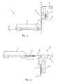
- Fig. 1 shows an evacuation system 1 for positioning and maintaining a position of an inflatable floatable unit 2 in relation to a maritime structure 3 during evacuation of persons at sea.
- the maritime structure 3 may be a vessel or an offshore installation. In the following, the maritime structure will mainly be described in relation to a vessel.
- the vessel may preferably be a passenger ship, such as a ferry or a cruise ship carrying a high number of passengers and crew members.
- the evacuation system 1 comprises a maritime structure 3, in Fig. 1 shown as a vessel, from which persons are to be evacuated, an inflatable floatable unit configured to be deployed from the maritime structure 3 into the water 4, and a bowsing system 5 comprising a first bowsing line 6 extending from the maritime structure 3 to the inflatable floatable unit 2.
- the bowsing system 5 also comprises a first bowsing winch 7 configured to, by means of the first bowsing line 6, bowse and position the inflatable floatable unit 2 in relation to the maritime structure 3 after it has been deployed from the maritime structure 3 into the water 4.
- the inflatable floatable unit 2 is stored in a deflated condition on the vessel 3 and after it has been deployed from the vessel 3, it is inflated on the water 4.
- the crew members handling the evacuation system 1 onboard the vessel will then use the bowsing winch 7 to initially bowse the inflatable floatable unit 2 in relation to the vessel, so that it is positioned correctly in view of the height from the water 4 to a deck 8 of the vessel 3.
- the bowsing system 5 further comprises a first hydraulic cylinder 9 having a piston 10 with a first piston end 11 extending outside the first hydraulic cylinder 9, and a first hydraulic accumulator 12 which is in fluid communication with the first hydraulic cylinder 9.
- the first piston end 11 is connected with the first bowsing line 6 between the first bowsing winch 7 and the inflatable floatable unit 2.
- the hydraulic cylinder together with the hydraulic accumulator absorb peak tensions in the bowsing line 6 caused inter alia by the movement of the inflatable floatable unit in the waves in relation to movement of the vessel and/or rolling of the vessel, so that it is avoided that the bowsing line and/or the inflatable floatable unit is/are damaged.
- An evacuation system 1 is thereby provided wherein the risk for failure of the bowsing system due to high peak forces caused by different movements of the inflatable floatable units and the vessel, respectively, is minimised considerably.
- the evacuation system 1 of Fig. 1 is shown without the maritime structure, and the inflatable floatable unit 2 is aligned with the bowsing system 5 for further description.
- the bowsing system 5 further comprises, in Fig. 2 , a first flexible member 13 which is connected with the first bowsing line 6, the first flexible member being arranged between the first bowsing line 6 and the inflatable floatable unit 2.
- the flexible member is configured to absorb the more constant small forces in the bowsing line caused by the wind load, the drift of the vessel and Stokes drift.
- the flexible member may also ensure that the crew members do not severely pre-tension the bowsing line 6 by means of the bowsing winch.
- the flexible member 13 may be a spring, an elastic element, or a plurality of elastic bands interconnected to form the flexible member.
- the bowsing system comprises a gearing system 14, and the bowsing line 6 is configured to be led through the gearing system 14 which is arranged between a deployment structure (not shown in Fig. 2 ) and the first piston end 11 of the hydraulic cylinder 9.
- the gearing system 14 will be further described below.
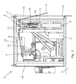
- Fig. 3 shows part of the evacuation system 1 comprising a deployment structure 15 connected to the maritime structure 3.
- the deployment structure 15 may be configured to house and store the deflated floatable unit (not shown) when it is not in use.
- the deployment structure 15 has a deployment side 16 facing away from the maritime structure 3.
- the bowsing winch 7, the hydraulic cylinder 9 and the hydraulic accumulator 12 are connected with the deployment structure 15.
- the bowsing system 5 comprises the gearing system 14, and the bowsing line 6 is configured to be led through the gearing system 14 which is arranged between the deployment structure 15 and the first piston end 11 of the hydraulic cylinder 9.
- the gearing system 14 comprises a plurality of structure turning points 17 connected with the deployment structure 15 and at least a piston turning point 18 connected with the first piston end 11. The bowsing line 6 is then led back and forth between the turning points 17, 18 as shown in Fig. 3 .
- the bowsing line 6 extends from a structure turning point 17 to a piston turning point 18 to another structure turning point 17 and then back to another piston turning point 18 and on to yet another structure turning point and subsequently to the bowsing winch 7.
- the number of structure turning points 17 is higher than the number of piston turning points 18.
- blocks may be arranged in connection with the turning points 17, 18 in order to facilitate smooth movement of the bowsing line 6 around the turning points 17, 18 and to prevent kinking of the bowsing line 6.
- the deployment structure 15 comprises horisontal beams 19 and vertical beams 20.
- the hydraulic cylinder 9 is arranged in a vertical position, wherein the first piston end 11 is configured to be moved up and down.
- the structure turning points 17 may primarily be arranged on or be connected to the horizontal beam 19 arranged above the hydraulic cylinder 9, when the hydraulic cylinder is arranged vertically as shown in Fig. 3 .
- the first piston end 11 is pulled upwards when it is absorbing the peak forces exerted on the bowsing line 6.
- the bowsing winch 7 may be a hydraulic winch and may be driven by a motor 21.
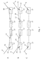
- the hydraulic cylinder 9 is arranged horizontally.
- the structure turning points 17 are primarily arranged on the vertical beam 20 of the deployment structure 15, when the hydraulic cylinder 9 is arranged horisontally.
- the first piston end 11 of the hydraulic cylinder 9 is movable back and forth in a horizontal direction.
- the embodiment shown in Fig. 4 is expedient when the hydraulic cylinder 9 shall be configured to absorb large forces in the bowsing line 6. Furthermore, additional room for movement of the first piston end 11 is obtained since it is able to project out of the deployment structure as shown in Fig. 4 .
- the first piston end 11 also has a piston turning point 18, so that the bowsing line 6 may be led back and forth between the structure turning points 17 and the piston turning point 18 in the gearing system 14.
- the first piston end 11 moves out in its extended position as shown in Fig. 4 , so that it is pressed into the hydraulic cylinder when it is absorbing the peak forces exerted on the bowsing line 6.
- a first valve (not shown in Fig. 4 ) is arranged between the hydraulic cylinder 9 and the hydraulic accumulator 12.
- the valve may be a throttle valve or a ball valve.
- the valve may be opened by a predetermined position of the first piston end 11.
- a wire 22 is provided between the first piston end 11 and the valve, whereby the wire 22 will be stretched during the outward movement of the first piston end 11. When the wire is stretched, it will, at a certain point, activate the valve so that it creates fluid communication between the hydraulic cylinder and the hydraulic accumulator.
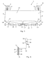
- the evacuation system 1 has a plurality of inflatable floatable units 2, here shown as two bowsed and positioned inflatable floatable units 2.
- the bowsing system 5 comprises two bowsing lines 6, two bowsing winches 7, two hydraulic cylinders 9, two hydraulic accumulators 12 and two gearing systems 14.
- the vessel 3 has a side 23 and one or more side turning points 24 arranged on the side 23 a predetermined distance below the deployment structure (not shown).
- the bowsing lines 6 may extend from the deployment structure to the inflatable floatable units 2 via the side turning points 24, whereby it is ensured that the inflatable floatable units 2 are only movable along the vessel side 23 between the side turning points 24.
- the bowsing lines 6 are, in this embodiment, divided into two sub-lines 25 which are connected to the flexible members 13.
- the flexible members 13 are connected with the sides 26 of the inflatable floatable units 2 facing away from the vessel side 23.
- the bowsing system 5 is configured to maintain the inflatable floatable units 2 in position in the transverse direction in relation to the vessel side 23.
- Fig. 6 shows the hydraulic cylinder 9 and the hydraulic accumulator 12.
- the embodiment shown in Fig. 6 may be used in connection with the bowsing system 5 described in connection with Fig. 3 above.
- the piston 27 has a second piston end 28 within the hydraulic cylinder 9 having a longitudinal extension, the piston being movable in the longitudinal extension of the hydraulic cylinder.
- the hydraulic cylinder 9 has a cylinder chamber 29 which is divided into a first chamber part 30 and a second chamber part 31 by the second piston end 28.
- the hydraulic accumulator 12 has a first part 32 comprising a gas and a second part 33 comprising a fluid, the second part 33 being fluidly connected with the first chamber part 30 of the hydraulic cylinder 9 via a conduit 34.
- the first part 32 and the second part 33 are separated from each other by a piston or a diaphragm 35, the hydraulic accumulator 12 having a volume and the hydraulic accumulator being set with a gas pre-charge pressure.
- a valve 36 is arranged between the accumulator 12 and the hydraulic cylinder 9.
- Fig. 7 shows different ways to connect the bowsing lines 6 to the inflatable floatable unit.
- the inflatable floatable units 2 comprise shells 37 which are all connected to the inflatable floatable units (not shown).
- the bowsing lines 6 extend from side turning points (not shown) towards the shells 37.
- the forces on the shells are distributed with a pulley 38 to two flexible members 13.
- the bowsing lines 6 extend from side turning points (not shown) towards the shells 37.
- the bowsing lines 6 are connected to two sub-lines 25, each having the flexible members 13.
- FIG. 8 an evacuation system 1 according to the invention is shown.
- Three evacuation chutes 39 extend from the deployment structure 15 to the inflatable floatable unit 2 for evacuation of persons from the vessel 3 to the inflatable floatable unit 2.
- the deployment structure 15 is also adapted to house a deployment arrangement having a displacement device.
- the deployment structure 15 may be substantially box-shaped, having a rectangular configuration, as shown in Fig. 8 , which facilitates interfacing and positioning of the deployment structure 15 on a vessel or offshore installation.
- the deployment arrangement may have a displacement device, and the displacement device is adapted to displace the one or more inflatable floatable units in a substantially horizontal and linear direction out of the deployment structure 15 and subsequently lower the one or more inflatable floatable units into the water in a substantially vertical direction.
- the inflatable floatable units may be positioned on a lifting platform inside the deployment structure, the lifting platform being adapted to carry the inflatable floatable units during deployment.
- the deployment arrangement may comprise the displacement device in the form of at least one crane arm pivotally arranged on a crane base, a deployment winch connected to a wire, a number of pulleys arranged on the crane arm and the crane base, and an actuator which is adapted to move the crane arm.
- the lifting platform with the inflatable floatable units is starting to be displaced sideways out in a substantially horizontal and linear direction of the deployment structure.
- the lifting platform is positioned outside the deployment structure by the displacement device having displaced it out of the deployment structure without exceeding the maximum height of the deployment structure, and is ready to be lowered by the displacement device in a substantially vertical direction.
- the present deployment arrangement does not occupy much room and it may be fully stored in the deployment structure, meaning that a compact evacuation system is obtained.
- Fig. 9 shows a force curve for the bowsing system according to the present invention.
- the flexible member In the A area of the curve, the flexible member is absorbing the small constant forces exerted on the bowsing system.
- the hydraulic cylinder/accumulator together with the flexible member absorb the major peak loads exerted on the bowsing system.
- the C area of the curve both the flexible member and the hydraulic system are at their maximum capacity, so here it is the inherent elasticity of the bowsing line which is absorbing the remaining peak loads.
Landscapes
- Engineering & Computer Science (AREA)
- Mechanical Engineering (AREA)
- Ocean & Marine Engineering (AREA)
- Chemical & Material Sciences (AREA)
- Combustion & Propulsion (AREA)
- Woven Fabrics (AREA)
- Battery Electrode And Active Subsutance (AREA)
Priority Applications (4)
| Application Number | Priority Date | Filing Date | Title |
|---|---|---|---|
| EP15174690.6A EP3112247A1 (fr) | 2015-06-30 | 2015-06-30 | Système d'évacuation |
| US15/736,157 US10526051B2 (en) | 2015-06-30 | 2016-06-29 | Evacuation system |
| EP16733500.9A EP3317176B1 (fr) | 2015-06-30 | 2016-06-29 | Système d'évacuation |
| PCT/EP2016/065079 WO2017001443A1 (fr) | 2015-06-30 | 2016-06-29 | Système d'évacuation |
Applications Claiming Priority (1)
| Application Number | Priority Date | Filing Date | Title |
|---|---|---|---|
| EP15174690.6A EP3112247A1 (fr) | 2015-06-30 | 2015-06-30 | Système d'évacuation |
Publications (1)
| Publication Number | Publication Date |
|---|---|
| EP3112247A1 true EP3112247A1 (fr) | 2017-01-04 |
Family
ID=53496565
Family Applications (2)
| Application Number | Title | Priority Date | Filing Date |
|---|---|---|---|
| EP15174690.6A Withdrawn EP3112247A1 (fr) | 2015-06-30 | 2015-06-30 | Système d'évacuation |
| EP16733500.9A Active EP3317176B1 (fr) | 2015-06-30 | 2016-06-29 | Système d'évacuation |
Family Applications After (1)
| Application Number | Title | Priority Date | Filing Date |
|---|---|---|---|
| EP16733500.9A Active EP3317176B1 (fr) | 2015-06-30 | 2016-06-29 | Système d'évacuation |
Country Status (3)
| Country | Link |
|---|---|
| US (1) | US10526051B2 (fr) |
| EP (2) | EP3112247A1 (fr) |
| WO (1) | WO2017001443A1 (fr) |
Cited By (3)
| Publication number | Priority date | Publication date | Assignee | Title |
|---|---|---|---|---|
| CN113044185A (zh) * | 2021-04-08 | 2021-06-29 | 中国人民解放军92578部队 | 一种气胀式救生筏系统及安装工艺 |
| WO2024180173A1 (fr) | 2023-03-01 | 2024-09-06 | Viking Life-Saving Equipment A/S | Système d'évacuation maritime |
| EP4484268A1 (fr) * | 2023-06-29 | 2025-01-01 | Viking Life-Saving Equipment A/S | Système d'évacuation maritime |
Citations (4)
| Publication number | Priority date | Publication date | Assignee | Title |
|---|---|---|---|---|
| FR2092713A1 (fr) * | 1970-06-14 | 1972-01-28 | Mediterranee Ateliers | Dispositifs pour lever une charge flottante |
| US5706755A (en) * | 1995-09-07 | 1998-01-13 | Seascape Systems Limited | Access and evacuation system for an offshore platform |
| WO2007129335A1 (fr) * | 2006-05-09 | 2007-11-15 | Navalimpianti S.P.A. | TREUIL AUTO-CONTRÔLÉ permettant de MANIPULER DES CHARGES SUR DES BATEAUX, DES EMBARCATIONS, DES NAVIRES, DES PONTONS, DES PLATEFORMES ET SIMILAIRES, EN PARTICULIER DES CANOTS DE SAUVETAGE OU AUTRE CHARGES |
| WO2012172081A1 (fr) * | 2011-06-17 | 2012-12-20 | Viking Life-Saving Equipment A/S | Unité flottante gonflable |
Family Cites Families (3)
| Publication number | Priority date | Publication date | Assignee | Title |
|---|---|---|---|---|
| US2091327A (en) * | 1936-04-21 | 1937-08-31 | James H Mcpartland | Lifeboat launching apparatus |
| DK175973B1 (da) * | 2002-04-04 | 2005-10-10 | Viking Life Saving Equip As | Fortöjningsststem |
| NO321073B1 (no) * | 2003-08-29 | 2006-03-13 | Viking Life Saving Equipment N | Anordning ved evakueringssystem |
-
2015
- 2015-06-30 EP EP15174690.6A patent/EP3112247A1/fr not_active Withdrawn
-
2016
- 2016-06-29 US US15/736,157 patent/US10526051B2/en active Active
- 2016-06-29 EP EP16733500.9A patent/EP3317176B1/fr active Active
- 2016-06-29 WO PCT/EP2016/065079 patent/WO2017001443A1/fr not_active Ceased
Patent Citations (4)
| Publication number | Priority date | Publication date | Assignee | Title |
|---|---|---|---|---|
| FR2092713A1 (fr) * | 1970-06-14 | 1972-01-28 | Mediterranee Ateliers | Dispositifs pour lever une charge flottante |
| US5706755A (en) * | 1995-09-07 | 1998-01-13 | Seascape Systems Limited | Access and evacuation system for an offshore platform |
| WO2007129335A1 (fr) * | 2006-05-09 | 2007-11-15 | Navalimpianti S.P.A. | TREUIL AUTO-CONTRÔLÉ permettant de MANIPULER DES CHARGES SUR DES BATEAUX, DES EMBARCATIONS, DES NAVIRES, DES PONTONS, DES PLATEFORMES ET SIMILAIRES, EN PARTICULIER DES CANOTS DE SAUVETAGE OU AUTRE CHARGES |
| WO2012172081A1 (fr) * | 2011-06-17 | 2012-12-20 | Viking Life-Saving Equipment A/S | Unité flottante gonflable |
Cited By (3)
| Publication number | Priority date | Publication date | Assignee | Title |
|---|---|---|---|---|
| CN113044185A (zh) * | 2021-04-08 | 2021-06-29 | 中国人民解放军92578部队 | 一种气胀式救生筏系统及安装工艺 |
| WO2024180173A1 (fr) | 2023-03-01 | 2024-09-06 | Viking Life-Saving Equipment A/S | Système d'évacuation maritime |
| EP4484268A1 (fr) * | 2023-06-29 | 2025-01-01 | Viking Life-Saving Equipment A/S | Système d'évacuation maritime |
Also Published As
| Publication number | Publication date |
|---|---|
| EP3317176B1 (fr) | 2020-07-08 |
| US10526051B2 (en) | 2020-01-07 |
| EP3317176A1 (fr) | 2018-05-09 |
| WO2017001443A1 (fr) | 2017-01-05 |
| US20180141620A1 (en) | 2018-05-24 |
Similar Documents
| Publication | Publication Date | Title |
|---|---|---|
| US5339760A (en) | Apparatus for securing a vessel to a submersible mooring buoy | |
| US20240300627A1 (en) | Sea Vessel Docking Station | |
| US8992127B2 (en) | Method and apparatus for subsea installations | |
| EP4081451B1 (fr) | Navire collecteur | |
| US2955626A (en) | Pipe lines for loading and unloading ships and other vessels | |
| US9340262B1 (en) | Inflatable launch and recovery system | |
| US9227701B2 (en) | Vessel comprising a mooring connector with a heave compensator | |
| EP3317176B1 (fr) | Système d'évacuation | |
| KR101222007B1 (ko) | 선체형상정보를 이용한 선박 계류 장치 | |
| WO2010032027A2 (fr) | Procédé de localisation d'une structure sous-marine pour déploiement | |
| EP2923941A1 (fr) | Dispositif amortisseur hydraulique maritime | |
| CN103231781A (zh) | 一种张力腿平台 | |
| CN102448809A (zh) | 分步式cam系泊系统 | |
| US8869727B1 (en) | Buoyant structure | |
| EP1829781B1 (fr) | Système d'amarrage pour unité flottable | |
| NO20220675A1 (en) | A heave compensated marine vessel | |
| WO2024180173A1 (fr) | Système d'évacuation maritime | |
| GB2591414A (en) | Multi vessel method and system for placing an object on a seabed |
Legal Events
| Date | Code | Title | Description |
|---|---|---|---|
| PUAI | Public reference made under article 153(3) epc to a published international application that has entered the european phase |
Free format text: ORIGINAL CODE: 0009012 |
|
| AK | Designated contracting states |
Kind code of ref document: A1 Designated state(s): AL AT BE BG CH CY CZ DE DK EE ES FI FR GB GR HR HU IE IS IT LI LT LU LV MC MK MT NL NO PL PT RO RS SE SI SK SM TR |
|
| AX | Request for extension of the european patent |
Extension state: BA ME |
|
| STAA | Information on the status of an ep patent application or granted ep patent |
Free format text: STATUS: THE APPLICATION IS DEEMED TO BE WITHDRAWN |
|
| 18D | Application deemed to be withdrawn |
Effective date: 20170705 |