EP3112254B1 - Composant structural d'aéronef conçu pour absorber et transmettre des forces - Google Patents
Composant structural d'aéronef conçu pour absorber et transmettre des forces Download PDFInfo
- Publication number
- EP3112254B1 EP3112254B1 EP15400026.9A EP15400026A EP3112254B1 EP 3112254 B1 EP3112254 B1 EP 3112254B1 EP 15400026 A EP15400026 A EP 15400026A EP 3112254 B1 EP3112254 B1 EP 3112254B1
- Authority
- EP
- European Patent Office
- Prior art keywords
- structural component
- frp
- aircraft structural
- reinforcing structure
- panel element
- Prior art date
- Legal status (The legal status is an assumption and is not a legal conclusion. Google has not performed a legal analysis and makes no representation as to the accuracy of the status listed.)
- Not-in-force
Links
Images




Classifications
-
- B—PERFORMING OPERATIONS; TRANSPORTING
- B64—AIRCRAFT; AVIATION; COSMONAUTICS
- B64C—AEROPLANES; HELICOPTERS
- B64C1/00—Fuselages; Constructional features common to fuselages, wings, stabilising surfaces or the like
-
- B—PERFORMING OPERATIONS; TRANSPORTING
- B64—AIRCRAFT; AVIATION; COSMONAUTICS
- B64C—AEROPLANES; HELICOPTERS
- B64C1/00—Fuselages; Constructional features common to fuselages, wings, stabilising surfaces or the like
- B64C1/06—Frames; Stringers; Longerons ; Fuselage sections
- B64C1/064—Stringers; Longerons
-
- B—PERFORMING OPERATIONS; TRANSPORTING
- B64—AIRCRAFT; AVIATION; COSMONAUTICS
- B64C—AEROPLANES; HELICOPTERS
- B64C1/00—Fuselages; Constructional features common to fuselages, wings, stabilising surfaces or the like
- B64C1/06—Frames; Stringers; Longerons ; Fuselage sections
- B64C1/068—Fuselage sections
- B64C1/069—Joining arrangements therefor
-
- B—PERFORMING OPERATIONS; TRANSPORTING
- B64—AIRCRAFT; AVIATION; COSMONAUTICS
- B64C—AEROPLANES; HELICOPTERS
- B64C25/00—Alighting gear
- B64C25/02—Undercarriages
- B64C25/08—Undercarriages non-fixed, e.g. jettisonable
- B64C25/10—Undercarriages non-fixed, e.g. jettisonable retractable, foldable, or the like
-
- B—PERFORMING OPERATIONS; TRANSPORTING
- B64—AIRCRAFT; AVIATION; COSMONAUTICS
- B64C—AEROPLANES; HELICOPTERS
- B64C25/00—Alighting gear
- B64C25/02—Undercarriages
- B64C25/08—Undercarriages non-fixed, e.g. jettisonable
- B64C25/10—Undercarriages non-fixed, e.g. jettisonable retractable, foldable, or the like
- B64C25/18—Operating mechanisms
- B64C25/20—Operating mechanisms mechanical
-
- B—PERFORMING OPERATIONS; TRANSPORTING
- B64—AIRCRAFT; AVIATION; COSMONAUTICS
- B64C—AEROPLANES; HELICOPTERS
- B64C25/00—Alighting gear
- B64C25/32—Alighting gear characterised by elements which contact the ground or similar surface
- B64C25/34—Alighting gear characterised by elements which contact the ground or similar surface wheeled type, e.g. multi-wheeled bogies
-
- B—PERFORMING OPERATIONS; TRANSPORTING
- B64—AIRCRAFT; AVIATION; COSMONAUTICS
- B64C—AEROPLANES; HELICOPTERS
- B64C27/00—Rotorcraft; Rotors peculiar thereto
-
- B—PERFORMING OPERATIONS; TRANSPORTING
- B64—AIRCRAFT; AVIATION; COSMONAUTICS
- B64C—AEROPLANES; HELICOPTERS
- B64C1/00—Fuselages; Constructional features common to fuselages, wings, stabilising surfaces or the like
- B64C2001/0054—Fuselage structures substantially made from particular materials
-
- B—PERFORMING OPERATIONS; TRANSPORTING
- B64—AIRCRAFT; AVIATION; COSMONAUTICS
- B64C—AEROPLANES; HELICOPTERS
- B64C25/00—Alighting gear
- B64C25/32—Alighting gear characterised by elements which contact the ground or similar surface
- B64C2025/325—Alighting gear characterised by elements which contact the ground or similar surface specially adapted for helicopters
-
- B—PERFORMING OPERATIONS; TRANSPORTING
- B64—AIRCRAFT; AVIATION; COSMONAUTICS
- B64C—AEROPLANES; HELICOPTERS
- B64C27/00—Rotorcraft; Rotors peculiar thereto
- B64C27/04—Helicopters
-
- F—MECHANICAL ENGINEERING; LIGHTING; HEATING; WEAPONS; BLASTING
- F16—ENGINEERING ELEMENTS AND UNITS; GENERAL MEASURES FOR PRODUCING AND MAINTAINING EFFECTIVE FUNCTIONING OF MACHINES OR INSTALLATIONS; THERMAL INSULATION IN GENERAL
- F16B—DEVICES FOR FASTENING OR SECURING CONSTRUCTIONAL ELEMENTS OR MACHINE PARTS TOGETHER, e.g. NAILS, BOLTS, CIRCLIPS, CLAMPS, CLIPS OR WEDGES; JOINTS OR JOINTING
- F16B11/00—Connecting constructional elements or machine parts by sticking or pressing them together, e.g. cold pressure welding
- F16B11/006—Connecting constructional elements or machine parts by sticking or pressing them together, e.g. cold pressure welding by gluing
-
- F—MECHANICAL ENGINEERING; LIGHTING; HEATING; WEAPONS; BLASTING
- F16—ENGINEERING ELEMENTS AND UNITS; GENERAL MEASURES FOR PRODUCING AND MAINTAINING EFFECTIVE FUNCTIONING OF MACHINES OR INSTALLATIONS; THERMAL INSULATION IN GENERAL
- F16B—DEVICES FOR FASTENING OR SECURING CONSTRUCTIONAL ELEMENTS OR MACHINE PARTS TOGETHER, e.g. NAILS, BOLTS, CIRCLIPS, CLAMPS, CLIPS OR WEDGES; JOINTS OR JOINTING
- F16B5/00—Joining sheets or plates, e.g. panels, to one another or to strips or bars parallel to them
- F16B5/01—Joining sheets or plates, e.g. panels, to one another or to strips or bars parallel to them by means of fastening elements specially adapted for honeycomb panels
-
- F—MECHANICAL ENGINEERING; LIGHTING; HEATING; WEAPONS; BLASTING
- F16—ENGINEERING ELEMENTS AND UNITS; GENERAL MEASURES FOR PRODUCING AND MAINTAINING EFFECTIVE FUNCTIONING OF MACHINES OR INSTALLATIONS; THERMAL INSULATION IN GENERAL
- F16B—DEVICES FOR FASTENING OR SECURING CONSTRUCTIONAL ELEMENTS OR MACHINE PARTS TOGETHER, e.g. NAILS, BOLTS, CIRCLIPS, CLAMPS, CLIPS OR WEDGES; JOINTS OR JOINTING
- F16B9/00—Connections of rods or tubular parts to flat surfaces at an angle
-
- F—MECHANICAL ENGINEERING; LIGHTING; HEATING; WEAPONS; BLASTING
- F16—ENGINEERING ELEMENTS AND UNITS; GENERAL MEASURES FOR PRODUCING AND MAINTAINING EFFECTIVE FUNCTIONING OF MACHINES OR INSTALLATIONS; THERMAL INSULATION IN GENERAL
- F16B—DEVICES FOR FASTENING OR SECURING CONSTRUCTIONAL ELEMENTS OR MACHINE PARTS TOGETHER, e.g. NAILS, BOLTS, CIRCLIPS, CLAMPS, CLIPS OR WEDGES; JOINTS OR JOINTING
- F16B9/00—Connections of rods or tubular parts to flat surfaces at an angle
- F16B9/05—Connections of rods or tubular parts to flat surfaces at an angle by way of an intermediate member
- F16B9/056—Connections of rods or tubular parts to flat surfaces at an angle by way of an intermediate member the intermediate member extending through the flat surface; the rod or tubular part extending through the flat surface
Definitions
- the invention is related to an aircraft structural component that is adapted for absorbing and transmitting forces in an aircraft, said aircraft structural component comprising the features of claim 1.
- aircraft structural components are used in aircrafts to strengthen locations where comparatively high loads must be transferred between different aircraft elements or structures.
- comparatively high loads occur with respect to a wheel-type landing gear of an aircraft and, more particularly, during landing of the aircraft, when comparatively high landing loads are induced via corresponding landing gear wheels of the wheel-type landing gear into the aircraft's fuselage.
- the aircraft is embodied as a rotary wing aircraft and, more particularly, as a 10 t-helicopter, vertical and horizontal loads of approximately 55 kN occur at a wheel-type nose landing gear of this helicopter and must be transferred to its fuselage.
- EP1714867 or US7413140 describes a rotary wing aircraft with an FRP fuselage and a wheel-type nose landing gear.
- the latter is attached to the FRP fuselage by means of an aircraft structural component that is implemented by using a machined bracket.
- such a machined bracket consists of an aluminum alloy such that corrosion thereof can at least be limited.
- the machined bracket is generally screwed or riveted, e. g. by means of Hi-Locks or Huck-bolts, to the FRP fuselage of the rotary wing aircraft. More specifically, the machined bracket is usually attached to longerons or crossmembers of a force-absorbing structure of the FRP fuselage and equipped with slide bearings, if the wheel-type nose landing gear is retractable.
- the document EP2818403 or US2014373315 describes an aircraft structural component with an FRP panel element and an FRP reinforcing element, which solves at least part of the above-described problems concerning use of a machined bracket made of an aluminum alloy.
- the FRP panel element is provided with a first opening extending therethrough and the reinforcing element is provided with a second opening extending therethrough, both openings being aligned.
- a bushing that is adapted to receive an attachment device for attaching a load to the aircraft structural component extends through both openings.
- a connecting element is arranged, which connects the FRP reinforcing element to the FRP panel element in a region of the FRP panel element adjacent to the first opening that extends through the FRP panel element.
- This connecting element between the FRP panel element and the FRP reinforcing element defines a hook and loop connection.
- the connecting element comprises a first section with a first plurality of hook and loop elements, which is disposed on the FRP panel element, and a second section with a second plurality of hook and loop elements, which is disposed on the FRP reinforcing element.
- the first and the second plurality of hook and loop elements are adapted to interact with each other so as to produce a hook and loop connection between the FRP panel element and the FRP reinforcing element.
- the document DE102011101450 or US2013125354 describes the connecting element that is used in the aircraft structural component according to the document EP2818403 in greater detail.
- this connecting element in the form of an additional hook and loop layer defines a detachable connection and is not designed to transfer comparatively high shear loads that occur e. g. in a wheel-type nose landing gear of a rotary wing aircraft as described above.
- the latter becomes comparatively heavy.
- this additional hook and loop layer is complicated and time-consuming in manufacture and, thus, expensive.
- the document US2011045232 describes a stringer for an aerospace vehicle.
- the stringer performs transferring bending loads in skin panels, and stiffening the skin panels so the panels don't buckle under loading.
- the stringers and skin panels may be made of fiber composites such as carbon fiber reinforced plastic (CFRP).
- CFRP carbon fiber reinforced plastic
- the composite stiffener has a stack of plies of reinforcing fibers and may be used in any aircraft structures that require stiffening.
- Such a stringer includes a web between a first flange and a second base, or is a Z-beam, a blade, a C-channel, a hat beam.
- the second base is co-cured with the skin panel.
- an object of the present invention to provide an aircraft structural component that is adapted for absorbing and transmitting forces in an aircraft and, in particular, in a rotary wing aircraft, said aircraft structural component being inherently protected against corrosion and exhibiting a comparatively low weight and a high resistance against forces that are to be absorbed and transferred, while providing for an improved distribution of absorbed forces.
- the at least one reinforcing structure is rigidly attached to the at least one panel element such that at least one cavity is defined between the at least one panel element and the at least one reinforcing structure.
- the at least one cavity is adapted for distributing forces that are absorbed by the aircraft structural component in operation.
- the at least one panel element and the at least one reinforcing structure are provided with at least one bearing element and the at least one reinforcing structure is spaced apart from the at least one panel element at least in the vicinity of this bearing element by an associated spacer.
- the at least one reinforcing structure, the at least one panel element and the spacer are preloaded in axial direction of the spacer with a screw nut that is attached by means of a screw connection to a bearing sleeve wall, on which the spacer may be accommodated.
- the spacer comprises FRP material, which may already be in a hard condition, i. e. cured, prior to a collective curing of the at least one reinforcing structure and the at least one panel element.
- the at least one panel element defines a longeron in a force-absorbing structure provided at a fuselage of an aircraft and the force-absorbing structure further comprises at least one crossmember that is arranged in a predetermined angle to said longeron.
- the at least one reinforcing structure is diagonally oriented from the vicinity of an associated crossmember to the vicinity of a floor or bottom shell of the aircraft.
- the at least one reinforcing structure can be oriented vertically from the vicinity of the floor to the vicinity of the bottom shell.
- the inventive aircraft structural component is manufactured as an integral part of a FRP-longeron in a force-absorbing structure provided at the fuselage and does, thus, not require any additional laborious installation as required with the above-described machined brackets.
- the inventive aircraft structural component permits a strong reinforcement of the fuselage in a region, where comparatively high forces are transmitted to the fuselage.
- an expensive supplementary corrosion protection can be omitted and it is not prone to fatigue.
- the inventive aircraft structural component has less weight and a lighter structure than the above-described machined brackets with screws and/or rivets, compared to which a weight reduction of approximately 30 % can be achieved. This leads to a saving in weight for a rotary wing aircraft, and in particular for a helicopter, of up to 2 kg.
- the at least one panel element of the inventive aircraft structural component is defined by a FRP-longeron in a force-absorbing structure provided at a fuselage of an aircraft, in particular of a rotary wing aircraft and, more particularly, of a helicopter.
- the aircraft structural component is a FRP component that is provided with at least one FRP-hollow body with preferably approximately 25 mm wall distance in height direction of the helicopter, which is e. g. provided in the area of a landing gear attachment of the helicopter.
- the FRP-hollow body can be filled with a foam core or a honeycomb core or can be designed without a durable core by means of a dissolvable core.
- the FRP-hollow body can also, be manufactured separately and attached to the FRP-longeron of the force-absorbing structure without using any core, e. g. by means of a riveted and/or bonded connection.
- any core e. g. by means of a riveted and/or bonded connection.
- the underlying filled FRP-hollow body is still understood as a hollow structure in the context of the present invention.
- the FRP-hollow body increases an underlying distance between corresponding outer surfaces of the FRP-longeron in the area of the aircraft structural component, i. e. a local thickness of a respective FRP-longeron. Consequently, this results e. g. in a landing gear attachment that is suitable to transfer all load components that are applied in operation, thereby resulting in a lighter design of the overall construction comprising the inventive aircraft structural component compared to a state of the art machined bracket. This applies particularly for transversal loads.
- a corresponding core in the FRP-hollow body has nowadays no sufficient proportion of load support due to currently available core materials with too little core shear strength.
- the core can be used exclusively for manufacturing reasons and may presumably shatter in operation while corresponding FRP-walls of the FRP-hollow body would be adapted to transfer occurring transversal loads due to their strength.
- a smaller helicopter i. e.
- each FRP-hollow body can either be formed by a dissolvable core, a foam core or a honeycomb core and is integrated into the inventive aircraft structural component while being cured together with the FRP-longeron of the force-absorbing structure.
- the FRP-hollow body may extend along a predetermined direction, e. g. vertically over the entire length of the aircraft structural component, and be connected on and/or to both sides to the FRP-longeron; in the case of a wheel-type nose landing gear it would e. g. extend between the bottom shell and the cockpit floor.
- a very strong attachment can also be achieved by a diagonally arranged FRP-hollow body connecting an area near a frame with an area near the cockpit floor. Thereby, a sufficient transversal load transfer is achieved.
- each FRP-longeron besides its fabric-prepreg and cores, e. g. the above-mentioned honeycomb cores, there is preferably additionally placed at least one core that is covered by fabric-prepreg to be cured collectively.
- the curing process in an associated autoclave is preferentially, but not necessarily, performed according to common manufacturing processes.
- Foam cores or honeycomb cores may remain in the FRP-hollow bodies.
- provision of a core for manufacturing reasons can be omitted.
- the FRP-hollow bodies and the FRP-longerons define a common opening or coaxially arranged openings that are aligned in the rotary wing aircraft's width direction, and wherein a bushing that is e.g. consisting of a titanium-alloy, stainless stell or bronze is placed.
- This bushing is used as a slide bearing or houses a slide bearing.
- a given attachment of the landing gear consists usually of two parts that are mirrored to the landing gear FRP-longerons with at least one integrated FRP-hollow body on each FRP-longeron and two cylinders to transmit respective landing gear forces.
- a bolt which aligns to a hole in the wheel-type nose landing gear and transmits the respective landing gear forces into the FRP-fuselage.
- the landing gear is pivot-mounted relative to this bolt-axis to retract it.
- the bolts can be mounted into the bushings either from outside or inside and can be fixed by transversal bolts. Washers can be used for axial gap adjustment.
- the at least one reinforcing structure comprises at least one strap-like element.
- the at least one strap-like element is rigidly attached to the at least one panel element.
- the at least one strap-like element is rigidly attached to the at least one panel element by means of riveting and/or bonding.
- the at least one reinforcing structure comprises a groove-like cross section.
- the at least one reinforcing structure is rigidly attached to the at least one panel element by means of riveting and/or bonding.
- the at least one panel element and the at least one reinforcing structure comprise fiber reinforced polymers.
- the at least one reinforcing structure is rigidly attached to the at least one panel element by means of a collective curing.
- the at least one cavity is at least partly filled with a foam core and/or a honeycomb core.
- At least one additional cavity is defined adjacent to the at least one cavity between the at least one panel element and the at least one reinforcing structure.
- the at least one additional cavity is at least partly filled with a foam core and/or a honeycomb core.
- the at least one panel element defines a longeron in a force-absorbing structure provided at a fuselage of an aircraft.
- the aircraft structural component is adapted for pivotally bearing a rotatable shaft of a wheel-type landing gear.
- a force transmitting attachment shaft is provided for pivotally connecting a rotatable shaft of a wheel-type landing gear to the at least one panel element and the at least one reinforcing structure.
- the force transmitting attachment shaft is non-pivotally connectable to the rotatable shaft by means of at least one associated fixation bolt.
- the at least one panel element and the at least one reinforcing structure are provided with at least one bearing element.
- the force transmitting attachment shaft is pivotally accommodated in the at least one bearing element.
- the at least one reinforcing structure is arranged with a predetermined shaping around the force transmitting attachment shaft.
- the at least one reinforcing structure is provided on either side of the at least one panel element.
- the at least one reinforcing structure is provided with a first geometry on a first side of the at least one panel element and with a second geometry on a second side of the at least one panel element.
- the at least one reinforcing structure comprises at least one opening that is adapted to allow washing out of a dissolvable core provided in the at least one cavity.
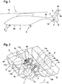
- FIG. 1 shows a vehicle 1 that is exemplarily illustrated as an aircraft, in particular as a rotary wing aircraft and, more particularly, as a helicopter.
- the vehicle 1 is hereinafter referred to as the "helicopter 1".
- the present invention is, however, not limited to helicopters and can likewise be applied to any other vehicle, for instance a vehicle that is controllable in a flowing medium, such as air or water, independent of a particular configuration thereof. Therefore, the helicopter 1 is only briefly described by way of example for illustrating a possible field of application of the present invention, but not for restricting the present invention thereto.
- the helicopter 1 illustratively comprises a fuselage 2 that defines a tail boom 2a.
- the fuselage 2 comprises a bottom shell 2b that is equipped with a force-absorbing structure 8.
- the force-absorbing structure 8 is at least adapted to support a wheel-type landing gear 6, 7 of the helicopter 1 that is illustratively implemented by a wheel-type rear landing gear 6 and a wheel-type front landing gear 7.
- the latter is hereinafter also referred to as the "wheel-type nose landing gear 7".
- the helicopter 1 comprises at least one main rotor 1a that is configured to provide lift and forward thrust during operation, and at least one counter-torque device 1b configured to provide counter-torque during operation, i. e. to counter the torque created by rotation of the at least one main rotor 1a for purposes of balancing the helicopter 1 in terms of yaw.
- the at least one counter-torque device 1b is illustratively provided at an aft section 3 of the tail boom 2a and, more specifically, at a shroud 3a of this aft section 3 of the tail boom 2a.
- the shroud 3a is preferably embodied for implementation of a Fenestron® tail rotor of the at least one counter-torque device 1b.
- the aft section 3 of the tail boom 2a is further provided with a bumper 4 and a fin 5 in the form of a T-tail having a tail wing 5a and a rudder 5b.
- the tail wing 5a is preferably adjustable in its inclination and can overtake the functioning of a horizontal stabilizer.
- the helicopter 1 is provided with a suitable horizontal stabilizer.
- the rudder 5b is preferably adapted to provide for enhanced directional control of the helicopter 1 and can be deflected to large angles to reduce a given lateral drag of the fin 5 in sideward flight.
- the T-tail configuration of the fin 5 and the rudder 5b, as well as the horizontal stabilizer are merely described for illustrating one exemplary embodiment of the aft section 3 of the tail boom 2a, and not for limiting the invention accordingly.
- the aft section 3 of the tail boom 2a may comprise an arbitrary configuration, independent on whether a T-tail fin or an otherwise configured fin is provided, with or without a rudder and with or without a horizontal stabilizer.
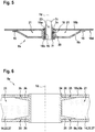
- FIG. 2 shows the fuselage 2 of the helicopter 1 of Figure 1 for further illustrating its force-absorbing structure 8 provided at the fuselage's bottom shell 2b in the region of the wheel-type nose landing gear 7.
- the latter comprises illustratively two wheels 7a, which are mounted to a mounting shaft 7b so as to be rotatable on this shaft 7b.
- the mounting shaft 7b is mounted to a shaft 7c, which is preferably rotatable around an associated rotation axis 7d, which is illustratively parallel to a corresponding rotation axis of the two wheels 7a.
- the wheel-type nose landing gear 7 is exemplarily designed as a retractable landing gear that can be retracted from an illustrated landing position into an associated flight position by means of a suitable rotation around the rotatable shaft 7c, as indicated with an arrow 13. In the flight position, the wheel-type nose landing gear 7 is preferably accommodated in an associated landing gear bay 12.
- the force-absorbing structure 8 comprises a plurality of longerons 10 and a plurality of crossmembers 11.
- the plurality of crossmembers 11 is preferably arranged with a predetermined angle relative to the plurality of longerons 10.
- the predetermined angle exemplarily amounts to approximately 90°.
- the plurality of longerons 10 preferably comprises at least two longerons 10a, 10b, which are preferentially implemented as panel elements and, more specifically, as elongated panels having a longitudinal extension that is at least approximately oriented in the longitudinal direction of the helicopter 1 of Figure 1 .
- the longeron 10a exemplarily defines a board side longeron and the longeron 10b a starboard side longeron, seen in forward flight direction of the helicopter 1 of Figure 1 .
- the plurality of crossmembers 11 preferably comprises at least two crossmembers 11a, 11b, which are preferentially also implemented as panel elements and, more specifically, as elongated panels having a longitudinal extension that is at least approximately oriented in the transverse direction of the helicopter 1 of Figure 1 .
- the crossmember 11a defines a front crossmember and the crossmember 11b defines a rear crossmember, seen in forward flight direction of the helicopter 1 of Figure 1 .
- the front crossmember 11a, the rear crossmember 11b, the board side longeron 10a and the starboard side longeron 10b define the landing gear bay 12.
- the force-absorbing structure 8 as a whole, but at least each one of the two longerons 10a, 10b, comprises FRP material and is preferentially implemented as a FRP component; i. e. a composite component. Therefore, the force-absorbing structure 8 is also referred to hereinafter as the "FRP-force-absorbing structure” and each one of the longerons 10a, 10b is also referred to as a "FRP-longeron” hereinafter.
- at least one of the crossmembers 11a, 11b comprises FRP material and is preferably implemented as a FRP component, i. e. a composite component. Therefore, each one of the two crossmembers 11a, 11b is also referred to hereinafter as a "FRP-crossmember".
- the FRP-force-absorbing structure 8 further comprises aircraft structural components 8a, which are preferably embodied as integral parts of the two FRP-longerons 10a, 10b and provided at least in a region of the two FRP-longerons 10a, 10b, where the rotatable shaft 7c is mounted to the latter.
- Each aircraft structural component 8a is at least adapted for absorbing and transmitting forces in the helicopter 1 of Figure 1 and, in the illustrated example, from its wheel-type nose landing gear 7 to its force-absorbing structure 8, i. e. the fuselage 2. Therefore, each aircraft structural component 8a is preferably adapted for pivotally bearing the rotatable shaft 7c.
- each aircraft structural component 8a is diagonally oriented from the bottom shell 2b towards an outer surface of the fuselage 2, preferably, but not necessarily, over the entire height of the force-absorbing structure 8.
- each aircraft structural component 8a comprises a reinforcing structure 9 that reinforces the associated FRP-longeron 10a, 10b of the plurality of FRP-longerons 10 in a predetermined region.
- the board side FRP-longeron 10a is reinforced by a board side reinforcing structure 9a and the starboard side FRP-longeron 10b is reinforced by a starboard side reinforcing structure 9b.
- each aircraft structural component 8a exemplarily comprises an optional honeycomb core 14.
- the board side FRP-longeron 10a comprises an optional board side honeycomb core 14a and the starboard side FRP-longeron 10b comprises an optional starboard side honeycomb core 14b.
- wheel-type nose landing gear 7 is shown and described for simplicity and clarity of the drawings and in order to explain the present invention by way of example with respect to this wheel-type nose landing gear 7.
- the present invention is not limited to an application with respect to such a wheel-type nose landing gear and can generally also be applied to the wheel-type rear landing gears 6 of Figure 1 . Even more generally, the present invention can be applied anywhere in the helicopter 1 where the aircraft structural component 8a can be used for absorbing and transmitting forces occurring in operation.
- Figure 3 shows the aircraft structural component 8a of Figure 2 . More specifically, Figure 3 representatively illustrates the aircraft structural component 8a that is implemented as an integral part of the starboard side FRP-longeron 10b of Figure 2 as an example for an aircraft structural component that is embodied according to the present invention.
- the aircraft structural component 8a is illustratively mounted to the rotatable shaft 7c of Figure 2 via an attachment shaft 7e that is provided with a support flange 7f such that an inner side surface 10c of the starboard side FRP-longeron 10b, which is also referred to as the "inside” hereinafter for simplicity, faces the rotatable shaft 7c and, consequently, faces away from the support flange 7f.
- the aircraft structural component 8a comprises at least one panel element, which is exemplarily embodied by the starboard side FRP-longeron 10b, and at least one reinforcing structure 9, which is exemplarily embodied by the starboard side reinforcing structure 9b that illustratively comprises an at least approximately rectangular groove-like cross section.
- the latter is preferably rigidly attached to the starboard side FRP-longeron 10b such that at least one cavity 21 is defined between the starboard side FRP-longeron 10b and the starboard side reinforcing structure 9b, thereby defining a FRP-hollow body.
- the at least one cavity 21 extends in cross section on both sides of the attachment shaft 7e.
- the at least one cavity 21 is adapted for distributing forces that are absorbed by the aircraft structural component 8a in operation.
- the starboard side reinforcing structure 9b is rigidly attached to the inside 10c of the starboard side FRP-longeron 10b. More specifically, the starboard side reinforcing structure 9b exemplarily comprises at least one strap-like element 15 and is in cross section illustratively provided with one strap-like element 15 on each side of the attachment shaft 7e. These strap-like elements 15 are used for rigidly attaching the starboard side reinforcing structure 9b to the inside 10c of the starboard side FRP-longeron 10b and are, therefore, rigidly attached to the starboard side FRP-longeron 10b.
- the starboard side reinforcing structure 9b and/or at least the strap-like elements 15 comprise FRP material and are preferentially implemented as FRP components, i. e. composite components that are made of so-called prepregs. Therefore, the starboard side reinforcing structure 9b is also referred to as the "starboard side reinforcing FRP-structure" and the strap-like elements 15 are also referred to as the "strap-like FRP-elements" hereinafter.
- the aircraft structural component 8a can advantageously be manufactured in a single step by means of a collective curing of the starboard side FRP-longeron 10b and the starboard side reinforcing structure 9b with the strap-like elements 15, whereby the starboard side reinforcing structure 9b, i. e. its strap-like elements 15, are rigidly attached to the starboard side FRP-longeron 10b.
- the aircraft structural component 8a is embodied as an integral, one-piece component.
- the starboard side FRP-longeron 10b and the starboard side reinforcing FRP-structure 9b can alternatively be cured separately and subsequently be attached rigidly to each other, e. g. by means of riveting and/or bonding.
- the strap-like elements 15 can be bonded and riveted onto the starboard side FRP-longeron 10b.
- the starboard side FRP-longeron 10b and the starboard side reinforcing FRP-structure 9b are provided with at least one bearing element 16.
- a single sleeve-like bearing element 16 is arranged on the attachment shaft 7e such that the latter is pivotally accommodated in the bearing element 16, i. e. rotatable relative to this bearing element 16.
- the bearing element 16 is accommodated in a bearing sleeve wall 17 such that the bearing element 16 is non-rotatable relative to this bearing sleeve wall 17.
- the bearing element 16 is force- or press-fitted and/or form-fitted into the bearing sleeve wall 17, bonded and/or glued there into.
- the bearing sleeve wall 17 is preferably made of titanium-alloy, stainless steel or bronze. According to one aspect of the present invention, the bearing sleeve wall 17 is inserted into the aircraft structural component 8a after curing. In this case, additional FRP-material must be foreseen in the aircraft structural component 8a before curing in order to allow matchdrilling of a hole basis fit without hurting the main structure of the cavities 21. Alternatively, the bearing sleeve wall 17 is positioned in the aircraft structural component 8a prior to curing and will, thus, be laminated with the overall structure.
- the bearing sleeve wall 17 comprises an outer collar that abuts against the support flange 7f of the attachment shaft 7e, and an inner collar against which the bearing element 16 abuts.
- the latter is fixedly retained between the inner collar of the bearing sleeve wall 17 and the support flange 7f.
- an external thread is provided on an outer circumference of the bearing sleeve wall 17, at least in the region of its inner collar.
- This external thread is provided so as to allow creation of a screw connection 18 between the bearing sleeve wall 17 and a screw nut 19, which is preferably made of titanium or a titanium-alloy.
- the screw connection 18 is preferably embodied to tighten the connection between the starboard side FRP-longeron 10b and the starboard side reinforcing FRP-structure 9b.
- this spacer 20 comprises FRP material and is preferentially implemented as a FRP component, i. e. a composite component, which can be cured together with the starboard side FRP-longeron 10b and the starboard side reinforcing FRP-structure 9b.
- the spacer 20 can be implemented as a precured component that is co-bonded into the aircraft structural component 8a. Such a co-bonded connection for the spacer 20 would be sufficient, as this connection is only subjected to pressure forces in operation.
- Figure 4 shows the aircraft structural component 8a of Figure 3 with the cavities 21.
- the cavities 21 are now illustratively at least partly filled with a foam core 22. If the cavities are entirely filled with the foam core 22, the latter preferentially serves at least as a spacing member for manufacturing reasons. More specifically, as the spacer 20 of Figure 3 may be co-bonded to the aircraft structural component 8a after the above-described collective curing, the foam core 22 is preferably inserted into the cavities 21 prior to this curing so that it serves as spacing member.
- Figure 5 shows the aircraft structural component 8a of Figure 3 with the starboard side FRP-longeron 10b and the starboard side reinforcing FRP-structure 9b that is provided with the strap-like elements 15.
- the starboard side reinforcing FRP-structure 9b is now exemplarily arranged on an outer side surface 10d of the starboard side FRP-longeron 10b, which is also referred to as the "outside" hereinafter for simplicity and which faces the support flange 7f of the attachment shaft 7e of Figure 3 .
- the attachment shaft 7e is preferably embodied as a force transmitting shaft that is preferentially non-pivotally connectable to the rotatable shaft 7c by means of at least one associated fixation bolt 23.
- a single fixation bolt 23 is used to rigidly attach the attachment shaft 7e to the rotatable shaft 7c such that the latter cannot rotate relative to the attachment shaft 7e.
- the starboard side reinforcing structure 9b now illustratively comprises an at least approximately trapezoidal groove-like cross section and the bearing element 16 is now exemplarily embodied as a gliding bearing in the form of a two-part component that comprises a first section 16a and a second section 16b.
- the first section 16a is preferably provided with a first outer collar that abuts against the starboard side FRP-longeron 10b and the second section 16b is provided with a second outer collar that preferably abuts against the starboard side reinforcing structure 9b and the support flange 7f of the attachment shaft 7e.
- the first and second sections 16a, 16b are preferably rigidly attached to each other, preferentially by a screw connection such as the screw connection 18 of Figure 3 , so that the first and second outer collars tighten the connection between the starboard side FRP-longeron 10b and the starboard side reinforcing FRP-structure 9b, which are again spaced apart from each other by means of the spacer 20 of Figure 3 .
- Figure 6 shows the aircraft structural component 8a of the preceding figures, which is now exemplarily provided with a bushing 24 instead of the bearing element 16, the bearing sleeve wall 17, the screw nut 19 and the spacer 20 described above.
- the bushing 24 is adapted for pivotally bearing the rotatable shaft 7c of the preceding figures such that the latter is rotatable relative to the bushing 24.
- the bushing 24 comprises at least two bonding surface ribs 26 that are respectively glued to the starboard side FRP-longeron 10b or the starboard side reinforcing FRP-structure 9b by means of a suitable adhesive 25. Additionally, or alternatively, the starboard side FRP-longeron 10b or the starboard side reinforcing FRP-structure 9b can be riveted and/or screwed to the at least two bonding surface ribs 26.
- the bonding surface ribs 26 are preferably embodied as ringshaped, i. e. annular outer collars or flanges of the bushing 24. A predetermined distance between the bonding surface ribs 26 determines an axial distance between the starboard side FRP-longeron 10b and the starboard side reinforcing FRP-structure 9b, in analogy to the spacer 20 of the preceding figures, for defining the cavities 21.
- the cavities 21 are now at least partly filled with a dissolvable core 27.
- a dissolvable core 27 can be washed out after curing, as described in more detail below with reference to Figure 15 .
- the cavities 21 may alternatively at least partly be filled with the foam core 22 of Figure 4 or the honeycomb core 14 of Figure 1 .
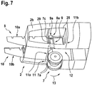
- Figure 7 shows the fuselage 2 of the helicopter 1 of Figure 1 with the force-absorbing structure 8 provided at the fuselage's bottom shell 2b in the region of the wheel-type nose landing gear 7.
- the force-absorbing structure 8 is now provided with the aircraft structural components 8a according to Figure 5 , which comprise the reinforcing structures 9 with an at least approximately trapezoidal groove-like cross section.
- the aircraft structural components 8a are now arranged vertically from a cockpit floor 28 defined by the fuselage 2 in direction of the wheels 7a of the wheel-type nose landing gear 7, preferably over the entire height of the force-absorbing structure 8, and not diagonally as illustrated in Figure 2 .
- the aircraft structural components 8a now define vertical reinforcing arrangements 29.
- FIG 8 shows variants (A) to (D) of the aircraft structural component 8a of Figure 7 , which are represented in a slightly simplified manner for simplicity and clarity of the drawings.
- the starboard side reinforcing FRP-structure 9b is representatively arranged on the outside 10d of the starboard side FRP-longeron 10b.
- the cavities 21 of the aircraft structural component 8a are exemplarily at least partly filled with the foam core 22. Furthermore, an additional cavity 21a is provided adjacent to one of the cavities 21.
- This additional cavity 21a exemplarily houses the starboard side honeycomb core 14b of Figure 2 , which can e. g. be attached to the foam core 22 by means of an adhesive film, which is preferentially applied prior to curing.
- Variant (B) mainly differs from variant (A) in that the cavities 21 are now hollow.
- Variant (C) mainly differs from variant (A) in that the cavities 21 are now subdivided into separate compartments by means of dividing walls 30 so that a transmissible transversal force can be increased advantageously.
- different cores can be inserted into the different compartments. For instance, a part of the compartments can be filled with the foam core 22, while another part is filled with the dissolvable core 27 of Figure 6 .
- only an at least partial filling with the foam core 22 is illustrated in all compartments.
- Variant (D) mainly differs from variant (C) in that the cavities 21 are now hollow again.
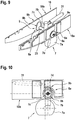
- FIG 9 shows the wheel-type nose landing gear 7 of Figure 2 and Figure 7 , which is pivotally mounted to the aircraft structural components 8a of the FRP-longerons 10 of Figure 2 and Figure 7 by means of the rotatable shaft 7c of Figure 2 and Figure 7 .
- the FRP-longerons 10 are now preferably designed in the so-called prepreg-sandwich-architecture with polyamide paper honeycomb cores.
- the rotatable shaft 7c is exemplarily connected via the mounting shaft 7b to an associated actuator 31, which is actuatable for rotating the rotatable shaft 7c via the mounting shaft 7b.
- each aircraft structural component 8a is now provided with at least one reinforcing FRP-structure 9 on either side of its associated FRP-longeron 10. More specifically, the aircraft structural component 8a that is provided at the starboard side FRP-longeron 10b is provided with the starboard side reinforcing FRP-structure 9b on the longeron side that faces the mounting shaft 7b as well as on the longeron side that faces away from the mounting shaft 7b. Similarly, the aircraft structural component 8a that is provided at the board side FRP-longeron 10a is provided with the board side reinforcing FRP-structure 9a on the longeron side that faces the mounting shaft 7b as well as on the longeron side that faces away from the mounting shaft 7b.
- each one of the reinforcing FRP-structures 9 is provided with a predetermined shaping and arranged around the attachment shaft 7e described above, i. e. around the rotatable shaft 7c.
- the board side reinforcing FRP-structure 9a on the longeron side of the board side FRP-longeron 10a that faces away from the mounting shaft 7b has a circular shaping, i. e. geometry, and surrounds the rotatable shaft 7c at least partly.
- This preferably similarly applies to the starboard side reinforcing FRP-structure 9b on the longeron side of the starboard side FRP-longeron 10b that faces away from the mounting shaft 7b.
- At least one of the reinforcing FRP-structures 9 is provided with a first geometry on a first side of its associated FRP-longeron 10 and with a second geometry on a second side of its associated FRP-longeron 10.
- the board side reinforcing FRP-structure 9a on the longeron side of the board side FRP-longeron 10a that faces away from the mounting shaft 7b has a circular geometry as described above
- the board side reinforcing FRP-structure 9a on the longeron side of the board side FRP-longeron 10a that faces the mounting shaft 7b illustratively comprises an egg-shaped geometry.
- This preferably similarly applies to the starboard side reinforcing FRP-structure 9b on the longeron side of the starboard side FRP-longeron 10b that faces the mounting shaft 7b and that preferably also comprises an egg-shaped geometry.
- Figure 10 shows the arrangement of Figure 9 for further illustrating the aircraft structural component 8a with the starboard side reinforcing FRP-structure 9b on the longeron side of the starboard side FRP-longeron 10b that faces away from the mounting shaft 7b and that comprises a circular shaping, i. e. geometry, and with the starboard side reinforcing FRP-structure 9b on the longeron side of the starboard side FRP-longeron 10b that faces the mounting shaft 7b and that preferably comprises an egg-shaped geometry.
- the circular geometry and the egg-shaped geometry lead to an asymmetric arrangement of the starboard side reinforcing FRP-structures 9b on the starboard side FRP-longeron 10b. Alternatively, a symmetrical arrangement can be contemplated in order to minimize distortion.
- Figure 10 further illustrates the actuator 31.
- FIG 11 shows the arrangement of Figure 9 with the aircraft structural components 8a that comprise the reinforcing FRP-structures 9 on either side of the associated FRP-longerons 10.
- each aircraft structural component 8a is now provided with at least two openings 32 that are adapted to allow washing out of a dissolvable core, such as the dissolvable core 27 of Figure 6 , provided in the respective aircraft structural component 8a. Therefore, the openings 32 are also referred to as the "washing holes” hereinafter.
- Each such washing hole 32 preferably comprises an opening dimension, i. e. a diameter of at least 12 mm.
- one washing hole 32 is provided in each one of the reinforcing FRP-structures 9. More specifically, one washing hole 32 is provided in the starboard side reinforcing FRP-structure 9b on the longeron side of the starboard side FRP-longeron 10b that faces away from the mounting shaft 7b, and another washing hole 32 is provided in the starboard side reinforcing FRP-structure 9b on the longeron side of the starboard side FRP-longeron 10b that faces the mounting shaft 7b. This preferably applies similarly to the board side reinforcing structures 9a of the board side FRP-longerons 10a.
- Figure 12 shows the arrangement of Figure 11 with the wheel-type nose landing gear 7 for further illustrating the provision of the board side reinforcing FRP-structures 9a on either side, i. e. the inside 10c and the outside 10d, of the board side FRP-longeron 10a and of the starboard side reinforcing FRP-structures 9b on either side, i. e. the inside 10c and the outside 10d, of the starboard side FRP-longeron 10b.
- Figure 12 further illustrates the non-rotatable attachment of the attachment shafts 7e to the rotatable shaft 7c by means of the fixation bolts 23.
- axial forces from the wheel-type nose landing gear 7 are transmitted through the transversal fixation bolts 23 and their front faces into the fuselage 2 of the helicopter 1 of Figure 1 .
- the radial forces of the wheel-type nose landing gear 7 are transmitted through the attachment shafts 7e, the surrounding bearing elements (16 in Figure 3 and Figure 4 ), the aircraft structural components 8a and the FRP-longerons 10 into the fuselage 2.
- Figure 13 shows the arrangement of Figure 12 for further illustrating an exemplary circular geometry according to Figure 9 of the board side and starboard side reinforcing FRP-structures 9a, 9b that are respectively provided on the outsides 10d of the board side and starboard side FRP-longerons 10a, 10b.
- Figure 13 also further illustrates an exemplary egg-shaped geometry according to Figure 9 of the board side and starboard side reinforcing FRP-structures 9a, 9b that are respectively provided on the insides 10c of the board side and starboard side FRP-longerons 10a, 10b.
- Figure 14 shows an enlargement of the arrangement of Figure 12 and Figure 13 for further illustrating provision of the dissolvable core 27 of Figure 6 in the aircraft structural component 8a, i. e. in the cavities 21 that are created by means of the starboard side reinforcing FRP-structures 9b.
- the starboard side reinforcing FRP-structures 9b define together with the starboard side FRP-longeron 10b a longeron and reinforcing substructure 33 of the force-absorbing structure 8 of Figure 2 and Figure 7 .
- Figure 15 shows the arrangement of Figure 14 after washing out of the dissolvable core 27 from the aircraft structural component 8a, i. e. from the cavities 21, via the washing holes 32 that are provided in the starboard side reinforcing FRP-structures 9b. Accordingly, the cavities 21 are now hollow.
- washing out process can be performed using any suitable dissolver that is adapted for dissolving the dissolvable core 27.
- suitable dissolver that is adapted for dissolving the dissolvable core 27.
- Such washing out processes, dissolvers and also suitable materials for the dissolvable core 27 are, however, well-known to the person skilled in the art, so that a detailed description thereof can be omitted hereinafter for simplicity and brevity of the description.
- Figure 16 shows an enlargement of the arrangement of Figure 12 after washing out of the dissolvable core 27 from the aircraft structural component 8a using the washing holes 32 that are provided in the starboard side reinforcing FRP-structures 9b. Accordingly, the cavities 21 are now hollow and, by way of example, four washing holes 32 are illustrated in the aircraft structural component 8a.
- bracket attachments a nose landing gear bracket attachment in a helicopter or airplane, a main landing gear bracket attachment in a helicopter or airplane, a main gearbox bracket attachment in a helicopter, a bracket attachment for foldable tail booms in a helicopter, a radome cover bracket in a helicopter or airplane and/or a mooring bracket attachment in a helicopter or airplane. Furthermore it is applicable to all force transmitting connections/load introductions.
Landscapes
- Engineering & Computer Science (AREA)
- Mechanical Engineering (AREA)
- Aviation & Aerospace Engineering (AREA)
- Laminated Bodies (AREA)
Claims (14)
- Composant structurel d'aéronef (8a) qui est apte à absorber et à transmettre des efforts dans un aéronef (1), ledit composant structurel d'aéronef (8a) comprenant au moins un élément formant panneau (10) et au moins une structure de renforcement (9),
ladite au moins une structure de renforcement (9) est rigidement attachée audit au moins un élément formant panneau (10) pour définir au moins une structure absorbant les efforts (8) de façon que, durant une utilisation dans un fuselage (2) d'aéronef (1), au moins une cavité (21) soit définie entre ledit au moins un élément formant panneau (10) et ladite au moins une structure de renforcement (9), ladite au moins une structure absorbant les efforts (8) définissant ladite au moins une cavité (21) et étant apte à distribuer les efforts qui sont absorbés par ledit composant structurel d'aéronef (8a) en fonctionnement ;
caractérisé en ce que ledit composant structurel d'aéronef (8a) soit apte à supporter à pivotement un arbre apte à pivoter (7c) d'un atterrisseur à roues (7) de l'aéronef (1) et en ce que ledit au moins un élément formant panneau (10) définisse un longeron (10a, 10b). - Composant structurel d'aéronef (8a) selon la revendication 1,
caractérisé en ce que ladite au moins une structure de renforcement (9) comprend au moins un élément formant bande (15), ledit au moins un élément formant bande (15) étant rigidement attaché audit au moins un élément formant panneau (10). - Composant structurel d'aéronef (8a) selon la revendication 2,
caractérisé en ce que ledit au moins un élément formant bande (15) est rigidement attaché audit au moins un élément formant panneau (10) par des moyens de rivetage et/ou d'adhésion. - Composant structurel d'aéronef (8a) selon la revendication 1,
caractérisé en ce que ladite au moins une structure de renforcement (9) comprend une section transversale en forme de gorge, ladite au moins une structure de renforcement (9) étant rigidement attachée audit au moins un élément formant panneau (10) par des moyens de rivetage et/ou d'adhésion. - Composant structurel d'aéronef (8a) selon la revendication 1,
caractérisé en ce que ledit au moins un élément formant panneau (10) et ladite au moins une structure de renforcement (9) comprennent des polymères renforcés de fibres. - Composant structurel d'aéronef (8a) selon la revendication 5,
caractérisé en ce que ladite au moins une structure de renforcement (9) est rigidement attachée audit au moins un élément formant panneau (10) au moyen d'une polymérisation conjointe. - Composant structurel d'aéronef (8a) selon la revendication 1,
caractérisé en ce que ladite au moins une cavité (21) est au moins en partie remplie d'un noyau en mousse (22) et/ou d'un noyau en nid d'abeille (14). - Composant structurel d'aéronef (8a) selon la revendication 1,
caractérisé en ce que au moins une cavité supplémentaire (21) est définie, adjacente à ladite au moins une cavité (21) entre ledit au moins un élément formant panneau (10) et ladite au moins une structure de renforcement (9), ladite au moins une cavité supplémentaire (21a) étant au moins en partie remplie d'un noyau en mousse (22) et/ou d'un noyau en nid d'abeille (14). - Composant structurel d'aéronef (8a) selon la revendication 1,
caractérisé en ce qu'un arbre de fixation transmettant les efforts (7e) est prévu pour raccorder à pivotement un arbre apte à pivoter (7c) d'un atterrisseur à roues (7) audit au moins un élément formant panneau (10) et à ladite au moins une structure de renforcement (9), ledit arbre de fixation transmettant les efforts (7e) étant raccordable par une liaison non pivotante audit arbre apte à pivoter (7c) au moyen d'au moins un boulon de fixation associé (23). - Composant structurel d'aéronef (8a) selon la revendication 9,
caractérisé en ce que ledit au moins un élément formant panneau (10) et ladite au moins une structure de renforcement (9) sont prévus avec au moins un élément de palier (16), ledit arbre de fixation transmettant les efforts (7e) étant logé à pivotement à l'intérieur dudit au moins un élément de palier (16). - Composant structurel d'aéronef (8a) selon la revendication 9,
caractérisé en ce que ladite au moins une structure de renforcement (9) est agencée suivant une forme prédéterminée autour dudit arbre de fixation transmettant les efforts (7e). - Composant structurel d'aéronef (8a) selon la revendication 9,
caractérisé en ce que ladite au moins une structure de renforcement (9) est prévue de chaque côté dudit au moins un élément formant panneau (10). - Composant structurel d'aéronef (8a) selon la revendication 12,
caractérisé en ce que ladite au moins une structure de renforcement (9) est pourvue d'une première géométrie sur un premier côté (10c) dudit au moins un élément formant panneau (10) et d'une seconde géométrie sur un second côté (10d) dudit au moins un élément formant panneau (10). - Composant structurel d'aéronef (8a) selon la revendication 1,
caractérisé en ce que ladite au moins une structure de renforcement (9) comprend au moins une ouverture (32) qui est apte à permettre l'évacuation par vidange d'un noyau soluble (27) prévu dans ladite au moins une cavité (21).
Priority Applications (2)
| Application Number | Priority Date | Filing Date | Title |
|---|---|---|---|
| EP15400026.9A EP3112254B1 (fr) | 2015-06-29 | 2015-06-29 | Composant structural d'aéronef conçu pour absorber et transmettre des forces |
| US15/176,292 US10399658B2 (en) | 2015-06-29 | 2016-06-08 | Aircraft structural component that is adapted for absorbing and transmitting forces in an aircraft |
Applications Claiming Priority (1)
| Application Number | Priority Date | Filing Date | Title |
|---|---|---|---|
| EP15400026.9A EP3112254B1 (fr) | 2015-06-29 | 2015-06-29 | Composant structural d'aéronef conçu pour absorber et transmettre des forces |
Publications (2)
| Publication Number | Publication Date |
|---|---|
| EP3112254A1 EP3112254A1 (fr) | 2017-01-04 |
| EP3112254B1 true EP3112254B1 (fr) | 2020-10-14 |
Family
ID=53776540
Family Applications (1)
| Application Number | Title | Priority Date | Filing Date |
|---|---|---|---|
| EP15400026.9A Not-in-force EP3112254B1 (fr) | 2015-06-29 | 2015-06-29 | Composant structural d'aéronef conçu pour absorber et transmettre des forces |
Country Status (2)
| Country | Link |
|---|---|
| US (1) | US10399658B2 (fr) |
| EP (1) | EP3112254B1 (fr) |
Families Citing this family (11)
| Publication number | Priority date | Publication date | Assignee | Title |
|---|---|---|---|---|
| EP3228539B1 (fr) * | 2016-04-06 | 2020-03-04 | Safran Landing Systems UK Limited | Ensemble de train d'atterrissage d'avion |
| EP3281861B1 (fr) * | 2016-08-11 | 2019-10-02 | AIRBUS HELICOPTERS DEUTSCHLAND GmbH | Aéronef à voilure tournante équipé d'un fuselage qui comprend au moins un panneau durci structurel |
| CN110496755B (zh) * | 2019-07-26 | 2021-02-12 | 中国科学院长春光学精密机械与物理研究所 | 一种固化工装的装配方法 |
| US11480207B2 (en) | 2020-01-31 | 2022-10-25 | The Boeing Company | Assembly to connect a panel to a support member |
| US11760472B2 (en) * | 2020-12-01 | 2023-09-19 | Textron Innovations Inc. | Rudders for rotorcraft yaw control systems |
| US12017748B2 (en) * | 2021-03-17 | 2024-06-25 | The Boeing Company | Fuselage barrel assemblies and methods of assembling fuselage barrel assemblies |
| US12275519B2 (en) * | 2022-06-01 | 2025-04-15 | The Boeing Company | Vertical intercostal structure for lateral support in aircraft interior |
| EP4382415B1 (fr) | 2022-12-06 | 2025-05-21 | AIRBUS HELICOPTERS DEUTSCHLAND GmbH | Giravion avec train d'atterrissage non escamotable |
| EP4382414B1 (fr) | 2022-12-06 | 2024-10-09 | AIRBUS HELICOPTERS DEUTSCHLAND GmbH | Giravion avec train d'atterrissage non escamotable |
| EP4382416B1 (fr) | 2022-12-08 | 2026-04-01 | AIRBUS HELICOPTERS DEUTSCHLAND GmbH | Train d'atterrissage non rétractable à roues pour giravion |
| EP4389598B1 (fr) | 2022-12-21 | 2025-10-22 | AIRBUS HELICOPTERS DEUTSCHLAND GmbH | Giravion avec train d'atterrissage non escamotable |
Family Cites Families (8)
| Publication number | Priority date | Publication date | Assignee | Title |
|---|---|---|---|---|
| US3991957A (en) * | 1974-03-18 | 1976-11-16 | The Boeing Company | Turnout landing gear array carrier for high-wing aircraft |
| US8720825B2 (en) * | 2005-03-31 | 2014-05-13 | The Boeing Company | Composite stiffeners for aerospace vehicles |
| FR2884802B1 (fr) | 2005-04-22 | 2008-11-14 | Eurocopter France | Structure porteuse et aeronef a voilure tournante |
| US8540921B2 (en) * | 2008-11-25 | 2013-09-24 | The Boeing Company | Method of forming a reinforced foam-filled composite stringer |
| DE102010003114A1 (de) * | 2010-03-22 | 2011-09-22 | Repower Systems Ag | Stegverbindung |
| DE102011101450B4 (de) | 2011-05-13 | 2014-07-24 | Airbus Operations Gmbh | Flugzeugbaugruppe und Verfahren zur Herstellung einer Flugzeugbaugruppe |
| US8651419B2 (en) * | 2011-07-18 | 2014-02-18 | The Boeing Company | Flexible truss frame and method of making the same |
| EP2818403B1 (fr) * | 2013-06-24 | 2016-02-10 | Airbus Operations GmbH | Composant structural d'aéronef localement renforcé |
-
2015
- 2015-06-29 EP EP15400026.9A patent/EP3112254B1/fr not_active Not-in-force
-
2016
- 2016-06-08 US US15/176,292 patent/US10399658B2/en active Active
Non-Patent Citations (1)
| Title |
|---|
| None * |
Also Published As
| Publication number | Publication date |
|---|---|
| US10399658B2 (en) | 2019-09-03 |
| EP3112254A1 (fr) | 2017-01-04 |
| US20160375979A1 (en) | 2016-12-29 |
Similar Documents
| Publication | Publication Date | Title |
|---|---|---|
| EP3112254B1 (fr) | Composant structural d'aéronef conçu pour absorber et transmettre des forces | |
| EP3031711B1 (fr) | Structure d'un aéronef pour amélioration d'angle de cognement de queue | |
| US10710712B2 (en) | Rotor blade afterbody | |
| CA3006933C (fr) | Un moyeu de rotor destine a un rotor de queue d'un giravion | |
| EP3118104B1 (fr) | Liaison aile fuselage brochée | |
| US9187169B2 (en) | High-wing-aircraft fuselage support structure | |
| US10227127B2 (en) | Fiber metal laminate reinforced wing spar for retractable underwing mounted landing gear assemblies | |
| EP2727824A2 (fr) | Fuselage d'aéronef renforcé | |
| CA3050051C (fr) | Un helicoptere compose equipe d'un arrangement de voilure fixe | |
| US10654559B2 (en) | Pitch control device for a ducted tail rotor of a rotorcraft | |
| EP2080612B2 (fr) | Distribution des points de charge de panneaux en nid d'abeille | |
| EP3095689B1 (fr) | Cloison de pressurisation pour un fuselage d'aéronef | |
| US8317130B1 (en) | Landing gear mount | |
| EP3437988B1 (fr) | Aile d'aéronef à rotors basculants présentant des zones de boucle | |
| CA3004225C (fr) | Un panneau etage composite comportant une zone etagee | |
| US10494090B2 (en) | Rotor hub with structural reinforcements | |
| EP2886450B1 (fr) | Surface de commande d'aéronef | |
| US20130056582A1 (en) | Landing gear mounted under an aircraft wing | |
| EP3556655B1 (fr) | Appareil de transport de marchandises dans un aéronef | |
| EP4151521B1 (fr) | Aéronef ayant une aile en flèche avant en configuration d'aile d'épaule | |
| EP3498591A1 (fr) | Poutre en treillis composite comportant une âme sandwich | |
| EP3392134B1 (fr) | Attache pour empennage horizontal d'un giravion | |
| EP4685048A1 (fr) | Panneau structurel à couches composites de carbone | |
| US10272997B1 (en) | Structural enclosure for an aircraft propulsion system |
Legal Events
| Date | Code | Title | Description |
|---|---|---|---|
| PUAI | Public reference made under article 153(3) epc to a published international application that has entered the european phase |
Free format text: ORIGINAL CODE: 0009012 |
|
| STAA | Information on the status of an ep patent application or granted ep patent |
Free format text: STATUS: THE APPLICATION HAS BEEN PUBLISHED |
|
| STAA | Information on the status of an ep patent application or granted ep patent |
Free format text: STATUS: REQUEST FOR EXAMINATION WAS MADE |
|
| AK | Designated contracting states |
Kind code of ref document: A1 Designated state(s): AL AT BE BG CH CY CZ DE DK EE ES FI FR GB GR HR HU IE IS IT LI LT LU LV MC MK MT NL NO PL PT RO RS SE SI SK SM TR |
|
| AX | Request for extension of the european patent |
Extension state: BA ME |
|
| 17P | Request for examination filed |
Effective date: 20161213 |
|
| RBV | Designated contracting states (corrected) |
Designated state(s): AL AT BE BG CH CY CZ DE DK EE ES FI FR GB GR HR HU IE IS IT LI LT LU LV MC MK MT NL NO PL PT RO RS SE SI SK SM TR |
|
| STAA | Information on the status of an ep patent application or granted ep patent |
Free format text: STATUS: EXAMINATION IS IN PROGRESS |
|
| 17Q | First examination report despatched |
Effective date: 20180713 |
|
| GRAP | Despatch of communication of intention to grant a patent |
Free format text: ORIGINAL CODE: EPIDOSNIGR1 |
|
| STAA | Information on the status of an ep patent application or granted ep patent |
Free format text: STATUS: GRANT OF PATENT IS INTENDED |
|
| RIC1 | Information provided on ipc code assigned before grant |
Ipc: F16B 5/01 20060101ALI20200527BHEP Ipc: F16B 11/00 20060101ALI20200527BHEP Ipc: B64C 1/00 20060101AFI20200527BHEP Ipc: F16B 9/00 20060101ALI20200527BHEP |
|
| INTG | Intention to grant announced |
Effective date: 20200617 |
|
| GRAS | Grant fee paid |
Free format text: ORIGINAL CODE: EPIDOSNIGR3 |
|
| GRAA | (expected) grant |
Free format text: ORIGINAL CODE: 0009210 |
|
| STAA | Information on the status of an ep patent application or granted ep patent |
Free format text: STATUS: THE PATENT HAS BEEN GRANTED |
|
| AK | Designated contracting states |
Kind code of ref document: B1 Designated state(s): AL AT BE BG CH CY CZ DE DK EE ES FI FR GB GR HR HU IE IS IT LI LT LU LV MC MK MT NL NO PL PT RO RS SE SI SK SM TR |
|
| REG | Reference to a national code |
Ref country code: GB Ref legal event code: FG4D |
|
| REG | Reference to a national code |
Ref country code: AT Ref legal event code: REF Ref document number: 1323316 Country of ref document: AT Kind code of ref document: T Effective date: 20201015 Ref country code: CH Ref legal event code: EP |
|
| REG | Reference to a national code |
Ref country code: DE Ref legal event code: R096 Ref document number: 602015060401 Country of ref document: DE |
|
| REG | Reference to a national code |
Ref country code: IE Ref legal event code: FG4D |
|
| REG | Reference to a national code |
Ref country code: AT Ref legal event code: MK05 Ref document number: 1323316 Country of ref document: AT Kind code of ref document: T Effective date: 20201014 |
|
| REG | Reference to a national code |
Ref country code: NL Ref legal event code: MP Effective date: 20201014 |
|
| PG25 | Lapsed in a contracting state [announced via postgrant information from national office to epo] |
Ref country code: GR Free format text: LAPSE BECAUSE OF FAILURE TO SUBMIT A TRANSLATION OF THE DESCRIPTION OR TO PAY THE FEE WITHIN THE PRESCRIBED TIME-LIMIT Effective date: 20210115 Ref country code: PT Free format text: LAPSE BECAUSE OF FAILURE TO SUBMIT A TRANSLATION OF THE DESCRIPTION OR TO PAY THE FEE WITHIN THE PRESCRIBED TIME-LIMIT Effective date: 20210215 Ref country code: NL Free format text: LAPSE BECAUSE OF FAILURE TO SUBMIT A TRANSLATION OF THE DESCRIPTION OR TO PAY THE FEE WITHIN THE PRESCRIBED TIME-LIMIT Effective date: 20201014 Ref country code: NO Free format text: LAPSE BECAUSE OF FAILURE TO SUBMIT A TRANSLATION OF THE DESCRIPTION OR TO PAY THE FEE WITHIN THE PRESCRIBED TIME-LIMIT Effective date: 20210114 Ref country code: RS Free format text: LAPSE BECAUSE OF FAILURE TO SUBMIT A TRANSLATION OF THE DESCRIPTION OR TO PAY THE FEE WITHIN THE PRESCRIBED TIME-LIMIT Effective date: 20201014 Ref country code: FI Free format text: LAPSE BECAUSE OF FAILURE TO SUBMIT A TRANSLATION OF THE DESCRIPTION OR TO PAY THE FEE WITHIN THE PRESCRIBED TIME-LIMIT Effective date: 20201014 |
|
| REG | Reference to a national code |
Ref country code: LT Ref legal event code: MG4D |
|
| PG25 | Lapsed in a contracting state [announced via postgrant information from national office to epo] |
Ref country code: LV Free format text: LAPSE BECAUSE OF FAILURE TO SUBMIT A TRANSLATION OF THE DESCRIPTION OR TO PAY THE FEE WITHIN THE PRESCRIBED TIME-LIMIT Effective date: 20201014 Ref country code: SE Free format text: LAPSE BECAUSE OF FAILURE TO SUBMIT A TRANSLATION OF THE DESCRIPTION OR TO PAY THE FEE WITHIN THE PRESCRIBED TIME-LIMIT Effective date: 20201014 Ref country code: PL Free format text: LAPSE BECAUSE OF FAILURE TO SUBMIT A TRANSLATION OF THE DESCRIPTION OR TO PAY THE FEE WITHIN THE PRESCRIBED TIME-LIMIT Effective date: 20201014 Ref country code: IS Free format text: LAPSE BECAUSE OF FAILURE TO SUBMIT A TRANSLATION OF THE DESCRIPTION OR TO PAY THE FEE WITHIN THE PRESCRIBED TIME-LIMIT Effective date: 20210214 Ref country code: BG Free format text: LAPSE BECAUSE OF FAILURE TO SUBMIT A TRANSLATION OF THE DESCRIPTION OR TO PAY THE FEE WITHIN THE PRESCRIBED TIME-LIMIT Effective date: 20210114 Ref country code: ES Free format text: LAPSE BECAUSE OF FAILURE TO SUBMIT A TRANSLATION OF THE DESCRIPTION OR TO PAY THE FEE WITHIN THE PRESCRIBED TIME-LIMIT Effective date: 20201014 Ref country code: AT Free format text: LAPSE BECAUSE OF FAILURE TO SUBMIT A TRANSLATION OF THE DESCRIPTION OR TO PAY THE FEE WITHIN THE PRESCRIBED TIME-LIMIT Effective date: 20201014 |
|
| PG25 | Lapsed in a contracting state [announced via postgrant information from national office to epo] |
Ref country code: HR Free format text: LAPSE BECAUSE OF FAILURE TO SUBMIT A TRANSLATION OF THE DESCRIPTION OR TO PAY THE FEE WITHIN THE PRESCRIBED TIME-LIMIT Effective date: 20201014 |
|
| REG | Reference to a national code |
Ref country code: DE Ref legal event code: R097 Ref document number: 602015060401 Country of ref document: DE |
|
| PG25 | Lapsed in a contracting state [announced via postgrant information from national office to epo] |
Ref country code: SK Free format text: LAPSE BECAUSE OF FAILURE TO SUBMIT A TRANSLATION OF THE DESCRIPTION OR TO PAY THE FEE WITHIN THE PRESCRIBED TIME-LIMIT Effective date: 20201014 Ref country code: RO Free format text: LAPSE BECAUSE OF FAILURE TO SUBMIT A TRANSLATION OF THE DESCRIPTION OR TO PAY THE FEE WITHIN THE PRESCRIBED TIME-LIMIT Effective date: 20201014 Ref country code: LT Free format text: LAPSE BECAUSE OF FAILURE TO SUBMIT A TRANSLATION OF THE DESCRIPTION OR TO PAY THE FEE WITHIN THE PRESCRIBED TIME-LIMIT Effective date: 20201014 Ref country code: CZ Free format text: LAPSE BECAUSE OF FAILURE TO SUBMIT A TRANSLATION OF THE DESCRIPTION OR TO PAY THE FEE WITHIN THE PRESCRIBED TIME-LIMIT Effective date: 20201014 Ref country code: EE Free format text: LAPSE BECAUSE OF FAILURE TO SUBMIT A TRANSLATION OF THE DESCRIPTION OR TO PAY THE FEE WITHIN THE PRESCRIBED TIME-LIMIT Effective date: 20201014 Ref country code: SM Free format text: LAPSE BECAUSE OF FAILURE TO SUBMIT A TRANSLATION OF THE DESCRIPTION OR TO PAY THE FEE WITHIN THE PRESCRIBED TIME-LIMIT Effective date: 20201014 |
|
| PLBE | No opposition filed within time limit |
Free format text: ORIGINAL CODE: 0009261 |
|
| STAA | Information on the status of an ep patent application or granted ep patent |
Free format text: STATUS: NO OPPOSITION FILED WITHIN TIME LIMIT |
|
| PG25 | Lapsed in a contracting state [announced via postgrant information from national office to epo] |
Ref country code: DK Free format text: LAPSE BECAUSE OF FAILURE TO SUBMIT A TRANSLATION OF THE DESCRIPTION OR TO PAY THE FEE WITHIN THE PRESCRIBED TIME-LIMIT Effective date: 20201014 |
|
| 26N | No opposition filed |
Effective date: 20210715 |
|
| PG25 | Lapsed in a contracting state [announced via postgrant information from national office to epo] |
Ref country code: AL Free format text: LAPSE BECAUSE OF FAILURE TO SUBMIT A TRANSLATION OF THE DESCRIPTION OR TO PAY THE FEE WITHIN THE PRESCRIBED TIME-LIMIT Effective date: 20201014 |
|
| PG25 | Lapsed in a contracting state [announced via postgrant information from national office to epo] |
Ref country code: SI Free format text: LAPSE BECAUSE OF FAILURE TO SUBMIT A TRANSLATION OF THE DESCRIPTION OR TO PAY THE FEE WITHIN THE PRESCRIBED TIME-LIMIT Effective date: 20201014 |
|
| PG25 | Lapsed in a contracting state [announced via postgrant information from national office to epo] |
Ref country code: MC Free format text: LAPSE BECAUSE OF FAILURE TO SUBMIT A TRANSLATION OF THE DESCRIPTION OR TO PAY THE FEE WITHIN THE PRESCRIBED TIME-LIMIT Effective date: 20201014 |
|
| REG | Reference to a national code |
Ref country code: CH Ref legal event code: PL |
|
| REG | Reference to a national code |
Ref country code: BE Ref legal event code: MM Effective date: 20210630 |
|
| PG25 | Lapsed in a contracting state [announced via postgrant information from national office to epo] |
Ref country code: LU Free format text: LAPSE BECAUSE OF NON-PAYMENT OF DUE FEES Effective date: 20210629 |
|
| PG25 | Lapsed in a contracting state [announced via postgrant information from national office to epo] |
Ref country code: LI Free format text: LAPSE BECAUSE OF NON-PAYMENT OF DUE FEES Effective date: 20210630 Ref country code: IE Free format text: LAPSE BECAUSE OF NON-PAYMENT OF DUE FEES Effective date: 20210629 Ref country code: CH Free format text: LAPSE BECAUSE OF NON-PAYMENT OF DUE FEES Effective date: 20210630 |
|
| PG25 | Lapsed in a contracting state [announced via postgrant information from national office to epo] |
Ref country code: IS Free format text: LAPSE BECAUSE OF FAILURE TO SUBMIT A TRANSLATION OF THE DESCRIPTION OR TO PAY THE FEE WITHIN THE PRESCRIBED TIME-LIMIT Effective date: 20210214 |
|
| PG25 | Lapsed in a contracting state [announced via postgrant information from national office to epo] |
Ref country code: BE Free format text: LAPSE BECAUSE OF NON-PAYMENT OF DUE FEES Effective date: 20210630 |
|
| PGFP | Annual fee paid to national office [announced via postgrant information from national office to epo] |
Ref country code: IT Payment date: 20220627 Year of fee payment: 8 Ref country code: GB Payment date: 20220627 Year of fee payment: 8 Ref country code: DE Payment date: 20220620 Year of fee payment: 8 |
|
| PGFP | Annual fee paid to national office [announced via postgrant information from national office to epo] |
Ref country code: FR Payment date: 20220628 Year of fee payment: 8 |
|
| PG25 | Lapsed in a contracting state [announced via postgrant information from national office to epo] |
Ref country code: HU Free format text: LAPSE BECAUSE OF FAILURE TO SUBMIT A TRANSLATION OF THE DESCRIPTION OR TO PAY THE FEE WITHIN THE PRESCRIBED TIME-LIMIT; INVALID AB INITIO Effective date: 20150629 |
|
| PG25 | Lapsed in a contracting state [announced via postgrant information from national office to epo] |
Ref country code: CY Free format text: LAPSE BECAUSE OF FAILURE TO SUBMIT A TRANSLATION OF THE DESCRIPTION OR TO PAY THE FEE WITHIN THE PRESCRIBED TIME-LIMIT Effective date: 20201014 |
|
| REG | Reference to a national code |
Ref country code: DE Ref legal event code: R119 Ref document number: 602015060401 Country of ref document: DE |
|
| GBPC | Gb: european patent ceased through non-payment of renewal fee |
Effective date: 20230629 |
|
| PG25 | Lapsed in a contracting state [announced via postgrant information from national office to epo] |
Ref country code: MK Free format text: LAPSE BECAUSE OF FAILURE TO SUBMIT A TRANSLATION OF THE DESCRIPTION OR TO PAY THE FEE WITHIN THE PRESCRIBED TIME-LIMIT Effective date: 20201014 Ref country code: DE Free format text: LAPSE BECAUSE OF NON-PAYMENT OF DUE FEES Effective date: 20240103 Ref country code: GB Free format text: LAPSE BECAUSE OF NON-PAYMENT OF DUE FEES Effective date: 20230629 |
|
| PG25 | Lapsed in a contracting state [announced via postgrant information from national office to epo] |
Ref country code: FR Free format text: LAPSE BECAUSE OF NON-PAYMENT OF DUE FEES Effective date: 20230630 |
|
| PG25 | Lapsed in a contracting state [announced via postgrant information from national office to epo] |
Ref country code: IT Free format text: LAPSE BECAUSE OF NON-PAYMENT OF DUE FEES Effective date: 20230629 |
|
| PG25 | Lapsed in a contracting state [announced via postgrant information from national office to epo] |
Ref country code: MT Free format text: LAPSE BECAUSE OF FAILURE TO SUBMIT A TRANSLATION OF THE DESCRIPTION OR TO PAY THE FEE WITHIN THE PRESCRIBED TIME-LIMIT Effective date: 20201014 |
|
| PG25 | Lapsed in a contracting state [announced via postgrant information from national office to epo] |
Ref country code: TR Free format text: LAPSE BECAUSE OF FAILURE TO SUBMIT A TRANSLATION OF THE DESCRIPTION OR TO PAY THE FEE WITHIN THE PRESCRIBED TIME-LIMIT Effective date: 20201014 |