EP3112521A1 - Appareil de traitement du linge - Google Patents
Appareil de traitement du linge Download PDFInfo
- Publication number
- EP3112521A1 EP3112521A1 EP16176913.8A EP16176913A EP3112521A1 EP 3112521 A1 EP3112521 A1 EP 3112521A1 EP 16176913 A EP16176913 A EP 16176913A EP 3112521 A1 EP3112521 A1 EP 3112521A1
- Authority
- EP
- European Patent Office
- Prior art keywords
- tub
- treatment apparatus
- drum
- laundry treatment
- water
- Prior art date
- Legal status (The legal status is an assumption and is not a legal conclusion. Google has not performed a legal analysis and makes no representation as to the accuracy of the status listed.)
- Granted
Links
Images



Classifications
-
- D—TEXTILES; PAPER
- D06—TREATMENT OF TEXTILES OR THE LIKE; LAUNDERING; FLEXIBLE MATERIALS NOT OTHERWISE PROVIDED FOR
- D06F—LAUNDERING, DRYING, IRONING, PRESSING OR FOLDING TEXTILE ARTICLES
- D06F37/00—Details specific to washing machines covered by groups D06F21/00 - D06F25/00
- D06F37/26—Casings; Tubs
-
- D—TEXTILES; PAPER
- D06—TREATMENT OF TEXTILES OR THE LIKE; LAUNDERING; FLEXIBLE MATERIALS NOT OTHERWISE PROVIDED FOR
- D06F—LAUNDERING, DRYING, IRONING, PRESSING OR FOLDING TEXTILE ARTICLES
- D06F37/00—Details specific to washing machines covered by groups D06F21/00 - D06F25/00
- D06F37/26—Casings; Tubs
- D06F37/28—Doors; Security means therefor
-
- D—TEXTILES; PAPER
- D06—TREATMENT OF TEXTILES OR THE LIKE; LAUNDERING; FLEXIBLE MATERIALS NOT OTHERWISE PROVIDED FOR
- D06F—LAUNDERING, DRYING, IRONING, PRESSING OR FOLDING TEXTILE ARTICLES
- D06F23/00—Washing machines with receptacles, e.g. perforated, having a rotary movement, e.g. oscillatory movement, the receptacle serving both for washing and for centrifugally separating water from the laundry
- D06F23/04—Washing machines with receptacles, e.g. perforated, having a rotary movement, e.g. oscillatory movement, the receptacle serving both for washing and for centrifugally separating water from the laundry and rotating or oscillating about a vertical axis
-
- D—TEXTILES; PAPER
- D06—TREATMENT OF TEXTILES OR THE LIKE; LAUNDERING; FLEXIBLE MATERIALS NOT OTHERWISE PROVIDED FOR
- D06F—LAUNDERING, DRYING, IRONING, PRESSING OR FOLDING TEXTILE ARTICLES
- D06F39/00—Details of washing machines not specific to a single type of machines covered by groups D06F9/00 - D06F27/00
- D06F39/08—Liquid supply or discharge arrangements
- D06F39/088—Liquid supply arrangements
-
- D—TEXTILES; PAPER
- D06—TREATMENT OF TEXTILES OR THE LIKE; LAUNDERING; FLEXIBLE MATERIALS NOT OTHERWISE PROVIDED FOR
- D06F—LAUNDERING, DRYING, IRONING, PRESSING OR FOLDING TEXTILE ARTICLES
- D06F29/00—Combinations of a washing machine with other separate apparatus in a common frame or the like, e.g. with rinsing apparatus
-
- D—TEXTILES; PAPER
- D06—TREATMENT OF TEXTILES OR THE LIKE; LAUNDERING; FLEXIBLE MATERIALS NOT OTHERWISE PROVIDED FOR
- D06F—LAUNDERING, DRYING, IRONING, PRESSING OR FOLDING TEXTILE ARTICLES
- D06F39/00—Details of washing machines not specific to a single type of machines covered by groups D06F9/00 - D06F27/00
- D06F39/12—Casings; Tubs
Definitions
- the present invention relates to a laundry treatment apparatus.
- a laundry treatment apparatus is a generic term for an apparatus that washes laundry (i.e. objects to be washed or objects to be dried), an apparatus that dries laundry, and an apparatus that may perform both washing and drying of laundry.
- Conventional laundry treatment apparatuses are classified into front loading type laundry treatment apparatuses configured such that laundry is introduced through an introduction aperture formed in the front surface of the apparatus and top loading type laundry treatment apparatuses configured such that laundry is introduced through an introduction aperture formed in the upper surface of the apparatus.
- a top loading type laundry treatment apparatus includes a tub having an introduction aperture formed in the upper surface thereof, a drum rotatably provided inside the tub, and a door for opening and closing the introduction aperture.
- Some conventional laundry treatment apparatuses having the configuration described above are devised to have a minimum volume in order to wash only a very small amount of laundry.
- Such a laundry treatment apparatus having a minimum volume has the feature of a very small distance between the introduction aperture and the upper end of the drum.
- the laundry treatment apparatus is an auxiliary laundry treatment apparatus that is coupled to a main laundry treatment apparatus, which performs main washing
- the volume of the laundry treatment apparatus is restricted, with the result that the distance between the introduction aperture and the upper end of the drum is very small.
- a front loading type auxiliary laundry treatment apparatus may be provided under the main laundry treatment apparatus.
- the auxiliary laundry treatment apparatus may be a drawer type laundry treatment apparatus, which may be configured to be discharged forward. Because the height of the auxiliary laundry treatment apparatus is less than the height of a conventional top loading type laundry treatment apparatus, the heights of the tub and the drum in the auxiliary laundry treatment apparatus are less than the heights of the tub and the drum in the conventional top loading type laundry treatment apparatus.
- impurities which are generated inside the tub when the drum is rotated to wash laundry, remain on the door.
- bubbles or impurities generated during washing of laundry may remain on the door, with the result that the bubbles or the impurities may be stuck to the laundry after the washing is completed, thereby reducing washing efficiency.
- the present invention is directed to a laundry treatment apparatus that substantially obviates one or more in problems due to limitations and disadvantages of the related art.
- One object of the present invention is to provide a laundry treatment apparatus, which may prevent impurities, generated inside a tub during washing, from remaining on a door, which is used to open and close an introduction aperture.
- another object of the present invention is to provide a laundry treatment apparatus, which may wash a door using the centrifugal force generated by the water stored in a tub while a drum is rotated.
- Another object of the present invention is to provide a laundry treatment apparatus, which may prevent bubbles or impurities from being stuck again to laundry when washing is completed.
- a laundry treatment apparatus includes a tub body for storing water therein, a tub cover for forming the upper surface of the tub body, an introduction aperture formed through the tub cover, a supply aperture provided in the tub cover for supplying water into the tub body, a drum rotatably provided in the tub body for storing laundry therein, the drum having an opening communicating with the introduction aperture, a door for opening and closing the introduction aperture, and an ejection unit for ejecting the water introduced into the supply aperture to the drum, wherein the ejection unit ejects water in at least two different directions.
- the ejection unit may further include an inclined surface extending upward from the surface of the body toward the ejection holes.
- the laundry treatment apparatus may further include a rotating shaft for rotating the drum and a washing unit for ejecting at least some of the water moved toward the tub cover to the door using the centrifugal force generated while the drum is rotated.
- the ejection unit may be spaced apart from the center of rotation of the drum by a predetermined distance.
- the washing unit may include a guide extending from the edge of the tub cover toward the introduction aperture and a discharge hole for discharging the water supplied through the guide in the direction in which the door is located.
- the washing unit may further include a barrier protruding from the tub cover toward the upper surface of the drum, the barrier surrounding the edge of the introduction aperture, and the discharge hole may be formed through the barrier.
- the door may be located above the introduction aperture, and the discharge hole may be inclined so as to discharge water toward the door.
- the door may include a frame rotatably coupled to the tub cover and a window provided in the frame such that the inside of the tub body is visible from outside the tub body, and the discharge hole may be inclined so as to discharge water toward the window.
- the guide may include a first guide for guiding water moved to the tub cover to the discharge hole when the drum is rotated in the clockwise direction and a second guide for guiding water moved to the tub cover to the discharge hole when the drum is rotated in the counterclockwise direction.
- the discharge hole may include a first discharge hole for discharging the water supplied through the first guide to the door and a second discharge hole for discharging the water supplied through the second guide to the door.
- the first discharge hole and the second discharge hole may be inclined such that the path of water discharged from the first discharge hole and the path of water discharged from the second discharge hole cross each other.
- the washing unit may include a plurality of washing units, at least two of the washing units being arranged so as to face each other.
- the laundry treatment apparatus may further include a cabinet and a drawer provided so as to be discharged from the cabinet for supporting the tub body.
- the laundry treatment apparatus may further include a rotating shaft for rotating the drum, the rotating shaft being orthogonal to the bottom surface of the tub body, wherein the door may include a frame rotatably coupled to the tub cover; a window provided in the frame such that the inside of the tub body is visible from outside the tub body; and a washing guide for guiding at least some of the water moved to the edge of the frame to the window using the centrifugal force generated while the drum is rotated.
- a laundry treatment apparatus in another aspect of the present invention, includes a tub body for storing water therein, a tub cover for forming the upper surface of the tub body, an introduction aperture formed through the tub cover, a supply aperture provided in the tub cover for supplying water into the tub body, a drum rotatably provided in the tub body for storing laundry therein, the drum having an opening communicating with the introduction aperture, a door for opening and closing the introduction aperture, a rotating shaft for rotating the drum, the rotating shaft being orthogonal to the bottom surface of the tub body, and a washing unit for ejecting at least some of the water moved toward the tub cover to the door using the centrifugal force generated while the drum is rotated.
- a laundry treatment apparatus in a further aspect of the present invention, includes a tub body for storing water therein, a tub cover for forming the upper surface of the tub body, an introduction aperture formed through the tub cover, a supply aperture provided in the tub cover for supplying water into the tub body, a drum rotatably provided in the tub body for storing laundry therein, the drum having an opening communicating with the introduction aperture, a door for opening and closing the introduction aperture, and a rotating shaft for rotating the drum, the rotating shaft being orthogonal to the bottom surface of the tub body, wherein the door includes a frame rotatably coupled to the tub cover, a window provided in the frame such that the inside of the tub body is visible from outside the tub body, and a washing guide for guiding at least some of water moved to the edge of the frame to the window using centrifugal force generated while the drum is rotated.
- the ejection holes may include a first ejection hole formed through the extension, a second ejection hole spaced apart from the first ejection hole by a predetermined angle, and a third ejection hole spaced apart from the second ejection hole by a predetermined angle.
- the inclined surface may include a first inclined surface inclined upward from the body toward the first ejection hole, a second inclined surface inclined upward from the body toward the second ejection hole, and a third inclined surface inclined upward from the body toward the third ejection hole.
- the ejection unit may be spaced apart from the center of rotation of the drum by a predetermined distance.
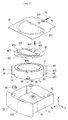
- a laundry treatment apparatus of the present invention designated by reference numeral 100, includes a cabinet 2, a drawer 3 provided so as to be discharged from the cabinet 2, a tub 4 provided inside the drawer 3 for storing water therein, and a drum 5 rotatably provided inside the tub 4 for storing laundry therein.
- the cabinet 2 may serve to define the external appearance of the laundry treatment apparatus 100, and may also simply serve as a space in which the drawer 3 is received. In any case, the cabinet 2 may be provided in the front surface thereof with an opening 21 for the insertion of the drawer 3.
- the drawer 3 includes a drawer body 31 configured so as to be inserted into the inside of the cabinet 2 through the opening 21, a drawer panel 33 fixed to the front surface of the drawer body 31 for opening and closing the opening 21, and a drawer cover 35 for forming the upper surface of the drawer body 31.
- the drawer panel 33 may serve as a handle for discharging the drawer body 31 from the cabinet 2.
- the drawer panel 33 may be provided with a control panel 331, which is used to input a control command associated with the operation of the laundry treatment apparatus 100 and to notify a user of a message associated with the operation of the laundry treatment apparatus 100.
- the drawer body 31 may have any shape so long as it can be inserted into the cabinet 2 through the opening 21 and can provide a space in which the tub 4 is received.
- FIG. 1 illustrates a hollow drawer body 31 having a hexahedral shape by way of example.
- the drawer cover 35 has a first through-hole 351 and a second through-hole 353 for communicating the inside of the drawer body 31 with the outside.
- the first through-hole 351 may be provided for the introduction and discharge of laundry, and the second through-hole 353 may be provided to supply water required to wash the laundry. A detailed description related thereto will follow.
- the tub 4 includes a tub body 41 located inside the drawer body 31 for storing water therein, and a tub cover 43 for forming the upper surface of the tub body 41.
- the tub body 41 may take the form of a cylinder having an open upper surface.
- a heater 411 for heating water may be provided in the tub body 41.
- the tub cover 43 may have an introduction aperture 431 for communicating the inside of the tub body 41 with the outside of the tub body 41, and a supply aperture 433 for introducing water into the tub body 41.
- the introduction aperture 431 may be provided under the first through-hole 351 provided in the drawer cover 35, and the supply aperture 433 may be provided under the second through-hole 353 provided in the drawer cover 35.
- the door 45 may include a frame 451 rotatably coupled to the tub cover 43 via a hinge 453, a window 455 provided in the frame 451, and a door handle 457 for separably coupling the frame 451 to the tub cover 43.
- the window 455 may be formed of a transparent material to allow the user to view the inside of the tub body 41 when the drawer 3 is discharged from the cabinet 2.
- any one of the frame 451 and the tub cover 43 may be provided with a sealing unit 49 for hermetically sealing a space between the frame 451 and the introduction aperture 431 when the door 45 closes the introduction aperture 431.
- the tub 4 having the configuration described above is coupled to the drawer body 31 via a tub support unit 6.
- the tub support unit 6 may include a first support member 61 provided at the drawer body 31, a second support member 63 provided at the tub body 41, and a connector 65 for connecting the first support member 61 and the second support member 63 to each other.
- the first connection piece 651 may be shaped so as to be movable in the first support member 61 while being seated in the first support member 61.
- the second connection piece 653 may be shaped so as to support the second support member 63 and to be movable in the second support member 63.
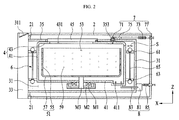
- FIG. 2 illustrates the case where the first connection piece 651 and the second connection piece 653 have spherical shapes by way of example
- FIG. 3 illustrates the case where the first connection piece 651 and the second connection piece 653 have semispherical surfaces in contact with the respective support members 61 and 63 by way of example.
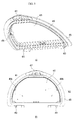
- the washing unit 91 illustrated in FIG. 4 serves to wash the door 45 using the centrifugal force generated while the drum 5 is rotated.
- FIG. 4(b) illustrates the case where the barrier 911 surrounds the entire introduction aperture 431.
- the barrier 911 may protrude from the edge of the introduction aperture 431 toward the drum 5.
- the discharge hole 913 may be inclined at a prescribed angle so as to allow water to be discharged toward the door 45.
- the discharge hole 913 may be inclined so as to allow water to be discharged to the window 455.
- the guide 915 may include a first guide 915a and a second guide 915b.
- the first guide 915a guides water, moved to the edge of the tub cover 43, to the discharge hole 913 when the drum 5 is rotated in the clockwise direction.
- the second guide 915b guides water, moved to the edge of the tub cover 43, to the discharge hole 913 when the drum 5 is rotated in the counterclockwise direction.
- the respective guides 915a and 915b may guide water to the same discharge hole 913.
- the discharge hole 913 includes a first discharge hole 913a and a second discharge hole 913b formed in the barrier 911
- the first guide 915a may guide water to the first discharge hole 913a
- the second guide 915b may guide water to the second discharge hole 913b.
- the washing unit 91 may wash the door 45 regardless of the direction in which the drum 5 is rotated so long as the number of revolutions per minute of the drum 5 is a preset reference number of revolutions per minute (i.e. the number of revolutions per minute by which the water inside the tub body 41 is moved upward to the tub cover 43).
- the respective discharge holes 913a and 913b may be inclined at a prescribed angle so that the path of water discharged from the first discharge hole 913a and the path of water discharged from the second discharge hole 913b cross each other. This serve to increase the washing range of the washing unit 91.
- the washing unit 91 having the configuration described above may be provided in a plural number along the edge of the introduction aperture 431, and the washing units 91 may be arranged so as to surround the introduction aperture 431. In addition, at least two of the washing units 91 may be arranged so as to face each other. This serves to increase the washing capability of the washing unit 91.
- the washing guide 456 may be provided at the edge of the window 455.
- water in the tub may move from the bottom surface of the tub to the edge of the frame 451 due to centrifugal force generated while the drum is rotated. Furthermore, the water may move around the edge of the frame 451.
- some of the water moved around the edge of the frame 451 may be guided toward the middle of the window 455 (W1 and W2). Consequently, it is possible to prevent the impurities from remaining on the window by the provision of the washing guide 456.
- one of the washing unit 91 and the washing guide 456 may be provided.
- both the washing unit 91 and the washing guide 456 may be provided.
- the body 931 may have an inclined surface, which is inclined upward toward the ejection holes 935, 937, and 939.
- the ejection unit 93 having the configuration described above may be spaced apart from the center of rotation of the drum 5 by a predetermined distance. If the ejection unit 93 is located on the center of rotation of the drum 5, the ejection unit 93 may eject water to the edge of the drum 5, but it is difficult for the ejection unit 93 to eject water to center of rotation of the drum 5, which is located under the ejection unit 93.
- the present invention has the effect of providing a laundry treatment apparatus, which may prevent impurities, generated inside a tub during washing, from remaining on a door, which is used to open and close an introduction aperture.
- the present invention has the effect of providing a laundry treatment apparatus, which may wash a door using centrifugal force generated by water stored in a tub while a drum is rotated.
- the present invention has the effect of providing a laundry treatment apparatus, which may remove bubbles or impurities from a door when washing is completed, thereby ensuring that a user does not doubt the ability of the laundry treatment apparatus.
- the present invention has the effect of providing a laundry treatment apparatus, which may prevent bubbles or impurities from being stuck again to laundry when the bubbles or impurities have been removed from a door, i.e. when washing is completed, thereby preventing the reduction of washing performance.
Landscapes
- Engineering & Computer Science (AREA)
- Textile Engineering (AREA)
- Main Body Construction Of Washing Machines And Laundry Dryers (AREA)
- Detail Structures Of Washing Machines And Dryers (AREA)
- Accessory Of Washing/Drying Machine, Commercial Washing/Drying Machine, Other Washing/Drying Machine (AREA)
Applications Claiming Priority (1)
| Application Number | Priority Date | Filing Date | Title |
|---|---|---|---|
| KR1020150092773A KR102402082B1 (ko) | 2015-06-30 | 2015-06-30 | 의류처리장치 |
Publications (2)
| Publication Number | Publication Date |
|---|---|
| EP3112521A1 true EP3112521A1 (fr) | 2017-01-04 |
| EP3112521B1 EP3112521B1 (fr) | 2019-01-02 |
Family
ID=56296599
Family Applications (1)
| Application Number | Title | Priority Date | Filing Date |
|---|---|---|---|
| EP16176913.8A Active EP3112521B1 (fr) | 2015-06-30 | 2016-06-29 | Appareil de traitement du linge |
Country Status (14)
| Country | Link |
|---|---|
| US (2) | US10487436B2 (fr) |
| EP (1) | EP3112521B1 (fr) |
| JP (1) | JP6980522B2 (fr) |
| KR (1) | KR102402082B1 (fr) |
| CN (1) | CN106319821B (fr) |
| AU (1) | AU2016285184B2 (fr) |
| BR (1) | BR112017003082B1 (fr) |
| CA (1) | CA2956309C (fr) |
| MX (1) | MX378626B (fr) |
| RU (1) | RU2664368C1 (fr) |
| TR (1) | TR201900170T4 (fr) |
| TW (1) | TWI626352B (fr) |
| WO (1) | WO2017003213A1 (fr) |
| ZA (1) | ZA201700610B (fr) |
Families Citing this family (6)
| Publication number | Priority date | Publication date | Assignee | Title |
|---|---|---|---|---|
| KR102402082B1 (ko) * | 2015-06-30 | 2022-05-26 | 엘지전자 주식회사 | 의류처리장치 |
| CN107366136B (zh) * | 2017-07-21 | 2022-03-18 | 合肥海尔洗衣机有限公司 | 一种洗衣机外桶盖及洗衣机 |
| CN108315908A (zh) * | 2018-02-02 | 2018-07-24 | 绍兴锦晨生物科技有限公司 | 一种纺织布清洗装置 |
| KR102604561B1 (ko) * | 2018-02-23 | 2023-11-22 | 엘지전자 주식회사 | 의류 건조기 |
| CN113026309B (zh) * | 2019-12-24 | 2024-07-16 | 佛山市顺德海尔电器有限公司 | 一种桶盖及洗衣机 |
| CN114592325B (zh) * | 2020-12-03 | 2025-09-26 | 青岛海尔洗涤电器有限公司 | 一种衣物处理装置 |
Citations (6)
| Publication number | Priority date | Publication date | Assignee | Title |
|---|---|---|---|---|
| GB2285270A (en) * | 1993-12-27 | 1995-07-05 | Toshiba Kk | Automatic washing machine with improved water sprinkling structure |
| US6351974B1 (en) * | 1998-08-18 | 2002-03-05 | Lg Electronics Inc. | Penetration type washing machine, method for controlling the same, and tub cover for the same |
| US20100064444A1 (en) * | 2008-09-12 | 2010-03-18 | Whirlpool Corporation | Method and apparatus for deflecting a spray of wash liquid to a desired location in a cleaning appliance |
| WO2012150539A2 (fr) * | 2011-05-02 | 2012-11-08 | Indesit Company S.P.A. | Appareil destiné à traiter des articles textiles et dispositif de lavage auxiliaire |
| US20150114046A1 (en) * | 2013-10-24 | 2015-04-30 | Lg Electronics Inc. | Washing machine |
| EP2949803A1 (fr) * | 2014-05-30 | 2015-12-02 | LG Electronics Inc. | Appareil de traitement du linge |
Family Cites Families (28)
| Publication number | Priority date | Publication date | Assignee | Title |
|---|---|---|---|---|
| US2254003A (en) * | 1940-02-10 | 1941-08-26 | Marco Louis De | Combined washing and rinsing machine |
| KR20020057120A (ko) * | 2000-12-30 | 2002-07-11 | 구자홍 | 드럼세탁기의 샤워장치 |
| KR100403029B1 (ko) * | 2001-09-28 | 2003-10-23 | 삼성전자주식회사 | 드럼세탁기 |
| KR20040003363A (ko) | 2002-07-02 | 2004-01-13 | 엘지전자 주식회사 | 세탁기의 배수부 구조 |
| KR100720574B1 (ko) * | 2003-10-17 | 2007-05-22 | 엘지전자 주식회사 | 세탁기 |
| KR101022225B1 (ko) * | 2003-11-18 | 2011-03-17 | 삼성전자주식회사 | 드럼세탁기 |
| US7918244B2 (en) * | 2005-05-02 | 2011-04-05 | Massachusetts Institute Of Technology | Microfluidic bubble logic devices |
| KR20070050583A (ko) * | 2005-11-11 | 2007-05-16 | 엘지전자 주식회사 | 드럼 세탁기 및 드럼 세탁기의 터브 세척 방법 |
| JP2007202638A (ja) * | 2006-01-31 | 2007-08-16 | Sanyo Electric Co Ltd | ドラム式洗濯機 |
| DE102007002184B4 (de) * | 2007-01-15 | 2018-03-15 | BSH Hausgeräte GmbH | Verfahren zum Waschen von Wäschestücken in einem programmgesteuerten Hausgerät, sowie solches Hausgerät |
| JP2008295941A (ja) * | 2007-06-04 | 2008-12-11 | Hitachi Appliances Inc | 洗濯機 |
| KR101466337B1 (ko) * | 2008-07-04 | 2014-11-28 | 삼성전자 주식회사 | 세탁기 |
| JP5489094B2 (ja) * | 2009-05-19 | 2014-05-14 | 株式会社東芝 | 脱水兼用洗濯機 |
| JP2011035190A (ja) * | 2009-08-03 | 2011-02-17 | Ricoh Co Ltd | マルチビームレーザ光量制御回路および該マルチビームレーザ光量制御回路を具備する光走査装置 |
| KR101647723B1 (ko) | 2009-12-03 | 2016-08-11 | 엘지전자 주식회사 | 세탁물 처리기기의 제어방법 |
| JP2013509283A (ja) * | 2009-11-02 | 2013-03-14 | エルジー エレクトロニクス インコーポレイティド | 洗濯方法及び洗濯機 |
| CN102115970B (zh) * | 2010-01-05 | 2015-04-08 | 海尔集团公司 | 一种用于洗衣机冲刷内桶外壁的高压喷淋装置及冲刷内桶外壁的方法 |
| US10081898B2 (en) * | 2010-04-30 | 2018-09-25 | Lg Electronics Inc. | Laundry apparatus |
| KR20110130664A (ko) * | 2010-05-28 | 2011-12-06 | 엘지전자 주식회사 | 세탁물 처리장치 |
| WO2012144263A1 (fr) * | 2011-04-19 | 2012-10-26 | 日立アプライアンス株式会社 | Machine à laver |
| CN105568623B (zh) * | 2011-04-19 | 2019-03-15 | 日立空调·家用电器株式会社 | 滚筒式洗衣机 |
| JP5608603B2 (ja) * | 2011-04-19 | 2014-10-15 | 日立アプライアンス株式会社 | 洗濯機 |
| WO2013091288A1 (fr) * | 2011-12-19 | 2013-06-27 | 海尔集团公司 | Dispositif et procédé de nettoyage d'un hublot d'observation et d'un anneau intercalaire d'étanchéité de hublot, et lave-linge les mettant en œuvre |
| US9115461B2 (en) * | 2011-12-21 | 2015-08-25 | Whirlpool Corporation | Door wash aid dispenser for a laundry treating appliance |
| CN203212860U (zh) * | 2013-04-08 | 2013-09-25 | 松下电器产业株式会社 | 洗衣机 |
| JP2015085080A (ja) * | 2013-11-01 | 2015-05-07 | パナソニックIpマネジメント株式会社 | 洗濯機 |
| CN203960595U (zh) * | 2014-05-16 | 2014-11-26 | Tcl家用电器(合肥)有限公司 | 出水头及采用该出水头的洗衣机 |
| KR102402082B1 (ko) * | 2015-06-30 | 2022-05-26 | 엘지전자 주식회사 | 의류처리장치 |
-
2015
- 2015-06-30 KR KR1020150092773A patent/KR102402082B1/ko active Active
-
2016
- 2016-06-16 TW TW105118992A patent/TWI626352B/zh active
- 2016-06-29 TR TR2019/00170T patent/TR201900170T4/tr unknown
- 2016-06-29 EP EP16176913.8A patent/EP3112521B1/fr active Active
- 2016-06-30 AU AU2016285184A patent/AU2016285184B2/en active Active
- 2016-06-30 BR BR112017003082-9A patent/BR112017003082B1/pt not_active IP Right Cessation
- 2016-06-30 JP JP2017510371A patent/JP6980522B2/ja not_active Expired - Fee Related
- 2016-06-30 CA CA2956309A patent/CA2956309C/fr active Active
- 2016-06-30 WO PCT/KR2016/007025 patent/WO2017003213A1/fr not_active Ceased
- 2016-06-30 US US15/197,815 patent/US10487436B2/en active Active
- 2016-06-30 RU RU2017107191A patent/RU2664368C1/ru active
- 2016-06-30 MX MX2017001967A patent/MX378626B/es unknown
- 2016-06-30 CN CN201610507593.XA patent/CN106319821B/zh active Active
-
2017
- 2017-01-25 ZA ZA2017/00610A patent/ZA201700610B/en unknown
-
2019
- 2019-11-25 US US16/694,667 patent/US11131052B2/en active Active
Patent Citations (6)
| Publication number | Priority date | Publication date | Assignee | Title |
|---|---|---|---|---|
| GB2285270A (en) * | 1993-12-27 | 1995-07-05 | Toshiba Kk | Automatic washing machine with improved water sprinkling structure |
| US6351974B1 (en) * | 1998-08-18 | 2002-03-05 | Lg Electronics Inc. | Penetration type washing machine, method for controlling the same, and tub cover for the same |
| US20100064444A1 (en) * | 2008-09-12 | 2010-03-18 | Whirlpool Corporation | Method and apparatus for deflecting a spray of wash liquid to a desired location in a cleaning appliance |
| WO2012150539A2 (fr) * | 2011-05-02 | 2012-11-08 | Indesit Company S.P.A. | Appareil destiné à traiter des articles textiles et dispositif de lavage auxiliaire |
| US20150114046A1 (en) * | 2013-10-24 | 2015-04-30 | Lg Electronics Inc. | Washing machine |
| EP2949803A1 (fr) * | 2014-05-30 | 2015-12-02 | LG Electronics Inc. | Appareil de traitement du linge |
Also Published As
| Publication number | Publication date |
|---|---|
| MX378626B (es) | 2025-03-10 |
| CN106319821A (zh) | 2017-01-11 |
| JP6980522B2 (ja) | 2021-12-15 |
| RU2664368C1 (ru) | 2018-08-16 |
| EP3112521B1 (fr) | 2019-01-02 |
| TWI626352B (zh) | 2018-06-11 |
| US20170002497A1 (en) | 2017-01-05 |
| AU2016285184A1 (en) | 2017-02-16 |
| US20200087832A1 (en) | 2020-03-19 |
| BR112017003082B1 (pt) | 2022-09-20 |
| ZA201700610B (en) | 2019-06-26 |
| KR20170002880A (ko) | 2017-01-09 |
| US11131052B2 (en) | 2021-09-28 |
| KR102402082B1 (ko) | 2022-05-26 |
| CA2956309C (fr) | 2019-09-24 |
| BR112017003082A2 (pt) | 2017-12-05 |
| AU2016285184B2 (en) | 2018-02-22 |
| TR201900170T4 (tr) | 2019-02-21 |
| WO2017003213A1 (fr) | 2017-01-05 |
| JP2018518993A (ja) | 2018-07-19 |
| TW201700824A (zh) | 2017-01-01 |
| CN106319821B (zh) | 2019-05-28 |
| MX2017001967A (es) | 2017-05-04 |
| CA2956309A1 (fr) | 2017-01-05 |
| US10487436B2 (en) | 2019-11-26 |
Similar Documents
| Publication | Publication Date | Title |
|---|---|---|
| EP3112524B1 (fr) | Appareil de traitement du linge | |
| US11131052B2 (en) | Laundry treatment apparatus | |
| US11898297B2 (en) | Laundry treatment apparatus | |
| US10113258B2 (en) | Laundry treatment apparatus |
Legal Events
| Date | Code | Title | Description |
|---|---|---|---|
| PUAI | Public reference made under article 153(3) epc to a published international application that has entered the european phase |
Free format text: ORIGINAL CODE: 0009012 |
|
| STAA | Information on the status of an ep patent application or granted ep patent |
Free format text: STATUS: REQUEST FOR EXAMINATION WAS MADE |
|
| 17P | Request for examination filed |
Effective date: 20160729 |
|
| AK | Designated contracting states |
Kind code of ref document: A1 Designated state(s): AL AT BE BG CH CY CZ DE DK EE ES FI FR GB GR HR HU IE IS IT LI LT LU LV MC MK MT NL NO PL PT RO RS SE SI SK SM TR |
|
| AX | Request for extension of the european patent |
Extension state: BA ME |
|
| RBV | Designated contracting states (corrected) |
Designated state(s): AL AT BE BG CH CY CZ DE DK EE ES FI FR GB GR HR HU IE IS IT LI LT LU LV MC MK MT NL NO PL PT RO RS SE SI SK SM TR |
|
| STAA | Information on the status of an ep patent application or granted ep patent |
Free format text: STATUS: EXAMINATION IS IN PROGRESS |
|
| 17Q | First examination report despatched |
Effective date: 20180124 |
|
| GRAP | Despatch of communication of intention to grant a patent |
Free format text: ORIGINAL CODE: EPIDOSNIGR1 |
|
| RIC1 | Information provided on ipc code assigned before grant |
Ipc: D06F 37/28 20060101AFI20180607BHEP Ipc: D06F 39/08 20060101ALI20180607BHEP Ipc: D06F 29/00 20060101ALN20180607BHEP |
|
| STAA | Information on the status of an ep patent application or granted ep patent |
Free format text: STATUS: GRANT OF PATENT IS INTENDED |
|
| INTG | Intention to grant announced |
Effective date: 20180712 |
|
| GRAS | Grant fee paid |
Free format text: ORIGINAL CODE: EPIDOSNIGR3 |
|
| GRAA | (expected) grant |
Free format text: ORIGINAL CODE: 0009210 |
|
| STAA | Information on the status of an ep patent application or granted ep patent |
Free format text: STATUS: THE PATENT HAS BEEN GRANTED |
|
| AK | Designated contracting states |
Kind code of ref document: B1 Designated state(s): AL AT BE BG CH CY CZ DE DK EE ES FI FR GB GR HR HU IE IS IT LI LT LU LV MC MK MT NL NO PL PT RO RS SE SI SK SM TR |
|
| REG | Reference to a national code |
Ref country code: GB Ref legal event code: FG4D |
|
| REG | Reference to a national code |
Ref country code: CH Ref legal event code: EP Ref country code: AT Ref legal event code: REF Ref document number: 1084519 Country of ref document: AT Kind code of ref document: T Effective date: 20190115 |
|
| REG | Reference to a national code |
Ref country code: IE Ref legal event code: FG4D |
|
| REG | Reference to a national code |
Ref country code: DE Ref legal event code: R096 Ref document number: 602016008870 Country of ref document: DE |
|
| REG | Reference to a national code |
Ref country code: NL Ref legal event code: MP Effective date: 20190102 |
|
| REG | Reference to a national code |
Ref country code: LT Ref legal event code: MG4D |
|
| REG | Reference to a national code |
Ref country code: AT Ref legal event code: MK05 Ref document number: 1084519 Country of ref document: AT Kind code of ref document: T Effective date: 20190102 |
|
| PG25 | Lapsed in a contracting state [announced via postgrant information from national office to epo] |
Ref country code: NL Free format text: LAPSE BECAUSE OF FAILURE TO SUBMIT A TRANSLATION OF THE DESCRIPTION OR TO PAY THE FEE WITHIN THE PRESCRIBED TIME-LIMIT Effective date: 20190102 |
|
| PG25 | Lapsed in a contracting state [announced via postgrant information from national office to epo] |
Ref country code: PT Free format text: LAPSE BECAUSE OF FAILURE TO SUBMIT A TRANSLATION OF THE DESCRIPTION OR TO PAY THE FEE WITHIN THE PRESCRIBED TIME-LIMIT Effective date: 20190502 Ref country code: SE Free format text: LAPSE BECAUSE OF FAILURE TO SUBMIT A TRANSLATION OF THE DESCRIPTION OR TO PAY THE FEE WITHIN THE PRESCRIBED TIME-LIMIT Effective date: 20190102 Ref country code: PL Free format text: LAPSE BECAUSE OF FAILURE TO SUBMIT A TRANSLATION OF THE DESCRIPTION OR TO PAY THE FEE WITHIN THE PRESCRIBED TIME-LIMIT Effective date: 20190102 Ref country code: LT Free format text: LAPSE BECAUSE OF FAILURE TO SUBMIT A TRANSLATION OF THE DESCRIPTION OR TO PAY THE FEE WITHIN THE PRESCRIBED TIME-LIMIT Effective date: 20190102 Ref country code: ES Free format text: LAPSE BECAUSE OF FAILURE TO SUBMIT A TRANSLATION OF THE DESCRIPTION OR TO PAY THE FEE WITHIN THE PRESCRIBED TIME-LIMIT Effective date: 20190102 Ref country code: FI Free format text: LAPSE BECAUSE OF FAILURE TO SUBMIT A TRANSLATION OF THE DESCRIPTION OR TO PAY THE FEE WITHIN THE PRESCRIBED TIME-LIMIT Effective date: 20190102 Ref country code: NO Free format text: LAPSE BECAUSE OF FAILURE TO SUBMIT A TRANSLATION OF THE DESCRIPTION OR TO PAY THE FEE WITHIN THE PRESCRIBED TIME-LIMIT Effective date: 20190402 |
|
| PG25 | Lapsed in a contracting state [announced via postgrant information from national office to epo] |
Ref country code: IS Free format text: LAPSE BECAUSE OF FAILURE TO SUBMIT A TRANSLATION OF THE DESCRIPTION OR TO PAY THE FEE WITHIN THE PRESCRIBED TIME-LIMIT Effective date: 20190502 Ref country code: BG Free format text: LAPSE BECAUSE OF FAILURE TO SUBMIT A TRANSLATION OF THE DESCRIPTION OR TO PAY THE FEE WITHIN THE PRESCRIBED TIME-LIMIT Effective date: 20190402 Ref country code: LV Free format text: LAPSE BECAUSE OF FAILURE TO SUBMIT A TRANSLATION OF THE DESCRIPTION OR TO PAY THE FEE WITHIN THE PRESCRIBED TIME-LIMIT Effective date: 20190102 Ref country code: RS Free format text: LAPSE BECAUSE OF FAILURE TO SUBMIT A TRANSLATION OF THE DESCRIPTION OR TO PAY THE FEE WITHIN THE PRESCRIBED TIME-LIMIT Effective date: 20190102 Ref country code: GR Free format text: LAPSE BECAUSE OF FAILURE TO SUBMIT A TRANSLATION OF THE DESCRIPTION OR TO PAY THE FEE WITHIN THE PRESCRIBED TIME-LIMIT Effective date: 20190403 Ref country code: HR Free format text: LAPSE BECAUSE OF FAILURE TO SUBMIT A TRANSLATION OF THE DESCRIPTION OR TO PAY THE FEE WITHIN THE PRESCRIBED TIME-LIMIT Effective date: 20190102 |
|
| REG | Reference to a national code |
Ref country code: DE Ref legal event code: R097 Ref document number: 602016008870 Country of ref document: DE |
|
| PG25 | Lapsed in a contracting state [announced via postgrant information from national office to epo] |
Ref country code: CZ Free format text: LAPSE BECAUSE OF FAILURE TO SUBMIT A TRANSLATION OF THE DESCRIPTION OR TO PAY THE FEE WITHIN THE PRESCRIBED TIME-LIMIT Effective date: 20190102 Ref country code: SK Free format text: LAPSE BECAUSE OF FAILURE TO SUBMIT A TRANSLATION OF THE DESCRIPTION OR TO PAY THE FEE WITHIN THE PRESCRIBED TIME-LIMIT Effective date: 20190102 Ref country code: AL Free format text: LAPSE BECAUSE OF FAILURE TO SUBMIT A TRANSLATION OF THE DESCRIPTION OR TO PAY THE FEE WITHIN THE PRESCRIBED TIME-LIMIT Effective date: 20190102 Ref country code: EE Free format text: LAPSE BECAUSE OF FAILURE TO SUBMIT A TRANSLATION OF THE DESCRIPTION OR TO PAY THE FEE WITHIN THE PRESCRIBED TIME-LIMIT Effective date: 20190102 Ref country code: AT Free format text: LAPSE BECAUSE OF FAILURE TO SUBMIT A TRANSLATION OF THE DESCRIPTION OR TO PAY THE FEE WITHIN THE PRESCRIBED TIME-LIMIT Effective date: 20190102 Ref country code: DK Free format text: LAPSE BECAUSE OF FAILURE TO SUBMIT A TRANSLATION OF THE DESCRIPTION OR TO PAY THE FEE WITHIN THE PRESCRIBED TIME-LIMIT Effective date: 20190102 Ref country code: RO Free format text: LAPSE BECAUSE OF FAILURE TO SUBMIT A TRANSLATION OF THE DESCRIPTION OR TO PAY THE FEE WITHIN THE PRESCRIBED TIME-LIMIT Effective date: 20190102 |
|
| PLBE | No opposition filed within time limit |
Free format text: ORIGINAL CODE: 0009261 |
|
| STAA | Information on the status of an ep patent application or granted ep patent |
Free format text: STATUS: NO OPPOSITION FILED WITHIN TIME LIMIT |
|
| PG25 | Lapsed in a contracting state [announced via postgrant information from national office to epo] |
Ref country code: SM Free format text: LAPSE BECAUSE OF FAILURE TO SUBMIT A TRANSLATION OF THE DESCRIPTION OR TO PAY THE FEE WITHIN THE PRESCRIBED TIME-LIMIT Effective date: 20190102 |
|
| 26N | No opposition filed |
Effective date: 20191003 |
|
| PG25 | Lapsed in a contracting state [announced via postgrant information from national office to epo] |
Ref country code: MC Free format text: LAPSE BECAUSE OF FAILURE TO SUBMIT A TRANSLATION OF THE DESCRIPTION OR TO PAY THE FEE WITHIN THE PRESCRIBED TIME-LIMIT Effective date: 20190102 |
|
| REG | Reference to a national code |
Ref country code: CH Ref legal event code: PL |
|
| PG25 | Lapsed in a contracting state [announced via postgrant information from national office to epo] |
Ref country code: SI Free format text: LAPSE BECAUSE OF FAILURE TO SUBMIT A TRANSLATION OF THE DESCRIPTION OR TO PAY THE FEE WITHIN THE PRESCRIBED TIME-LIMIT Effective date: 20190102 |
|
| REG | Reference to a national code |
Ref country code: BE Ref legal event code: MM Effective date: 20190630 |
|
| PG25 | Lapsed in a contracting state [announced via postgrant information from national office to epo] |
Ref country code: IE Free format text: LAPSE BECAUSE OF NON-PAYMENT OF DUE FEES Effective date: 20190629 |
|
| PG25 | Lapsed in a contracting state [announced via postgrant information from national office to epo] |
Ref country code: LI Free format text: LAPSE BECAUSE OF NON-PAYMENT OF DUE FEES Effective date: 20190630 Ref country code: BE Free format text: LAPSE BECAUSE OF NON-PAYMENT OF DUE FEES Effective date: 20190630 Ref country code: LU Free format text: LAPSE BECAUSE OF NON-PAYMENT OF DUE FEES Effective date: 20190629 Ref country code: CH Free format text: LAPSE BECAUSE OF NON-PAYMENT OF DUE FEES Effective date: 20190630 |
|
| PG25 | Lapsed in a contracting state [announced via postgrant information from national office to epo] |
Ref country code: FR Free format text: LAPSE BECAUSE OF NON-PAYMENT OF DUE FEES Effective date: 20190630 |
|
| PG25 | Lapsed in a contracting state [announced via postgrant information from national office to epo] |
Ref country code: CY Free format text: LAPSE BECAUSE OF FAILURE TO SUBMIT A TRANSLATION OF THE DESCRIPTION OR TO PAY THE FEE WITHIN THE PRESCRIBED TIME-LIMIT Effective date: 20190102 |
|
| PG25 | Lapsed in a contracting state [announced via postgrant information from national office to epo] |
Ref country code: HU Free format text: LAPSE BECAUSE OF FAILURE TO SUBMIT A TRANSLATION OF THE DESCRIPTION OR TO PAY THE FEE WITHIN THE PRESCRIBED TIME-LIMIT; INVALID AB INITIO Effective date: 20160629 Ref country code: MT Free format text: LAPSE BECAUSE OF FAILURE TO SUBMIT A TRANSLATION OF THE DESCRIPTION OR TO PAY THE FEE WITHIN THE PRESCRIBED TIME-LIMIT Effective date: 20190102 |
|
| PG25 | Lapsed in a contracting state [announced via postgrant information from national office to epo] |
Ref country code: MK Free format text: LAPSE BECAUSE OF FAILURE TO SUBMIT A TRANSLATION OF THE DESCRIPTION OR TO PAY THE FEE WITHIN THE PRESCRIBED TIME-LIMIT Effective date: 20190102 |
|
| P01 | Opt-out of the competence of the unified patent court (upc) registered |
Effective date: 20230524 |
|
| PGFP | Annual fee paid to national office [announced via postgrant information from national office to epo] |
Ref country code: DE Payment date: 20250508 Year of fee payment: 10 |
|
| PGFP | Annual fee paid to national office [announced via postgrant information from national office to epo] |
Ref country code: GB Payment date: 20250508 Year of fee payment: 10 |
|
| PGFP | Annual fee paid to national office [announced via postgrant information from national office to epo] |
Ref country code: IT Payment date: 20250512 Year of fee payment: 10 |
|
| PGFP | Annual fee paid to national office [announced via postgrant information from national office to epo] |
Ref country code: TR Payment date: 20250509 Year of fee payment: 10 |