EP3112590A1 - Buse bombée de commande de flux secondaire et performance optimale de diffuseur - Google Patents
Buse bombée de commande de flux secondaire et performance optimale de diffuseur Download PDFInfo
- Publication number
- EP3112590A1 EP3112590A1 EP16177103.5A EP16177103A EP3112590A1 EP 3112590 A1 EP3112590 A1 EP 3112590A1 EP 16177103 A EP16177103 A EP 16177103A EP 3112590 A1 EP3112590 A1 EP 3112590A1
- Authority
- EP
- European Patent Office
- Prior art keywords
- nozzle
- height
- turbine
- extending
- suction side
- Prior art date
- Legal status (The legal status is an assumption and is not a legal conclusion. Google has not performed a legal analysis and makes no representation as to the accuracy of the status listed.)
- Granted
Links
Images


Classifications
-
- F—MECHANICAL ENGINEERING; LIGHTING; HEATING; WEAPONS; BLASTING
- F01—MACHINES OR ENGINES IN GENERAL; ENGINE PLANTS IN GENERAL; STEAM ENGINES
- F01D—NON-POSITIVE DISPLACEMENT MACHINES OR ENGINES, e.g. STEAM TURBINES
- F01D9/00—Stators
- F01D9/02—Nozzles; Nozzle boxes; Stator blades; Guide conduits, e.g. individual nozzles
- F01D9/04—Nozzles; Nozzle boxes; Stator blades; Guide conduits, e.g. individual nozzles forming ring or sector
- F01D9/047—Nozzle boxes
-
- F—MECHANICAL ENGINEERING; LIGHTING; HEATING; WEAPONS; BLASTING
- F01—MACHINES OR ENGINES IN GENERAL; ENGINE PLANTS IN GENERAL; STEAM ENGINES
- F01D—NON-POSITIVE DISPLACEMENT MACHINES OR ENGINES, e.g. STEAM TURBINES
- F01D9/00—Stators
- F01D9/02—Nozzles; Nozzle boxes; Stator blades; Guide conduits, e.g. individual nozzles
-
- F—MECHANICAL ENGINEERING; LIGHTING; HEATING; WEAPONS; BLASTING
- F01—MACHINES OR ENGINES IN GENERAL; ENGINE PLANTS IN GENERAL; STEAM ENGINES
- F01D—NON-POSITIVE DISPLACEMENT MACHINES OR ENGINES, e.g. STEAM TURBINES
- F01D5/00—Blades; Blade-carrying members; Heating, heat-insulating, cooling or antivibration means on the blades or the members
- F01D5/12—Blades
- F01D5/14—Form or construction
- F01D5/141—Shape, i.e. outer, aerodynamic form
-
- F—MECHANICAL ENGINEERING; LIGHTING; HEATING; WEAPONS; BLASTING
- F01—MACHINES OR ENGINES IN GENERAL; ENGINE PLANTS IN GENERAL; STEAM ENGINES
- F01D—NON-POSITIVE DISPLACEMENT MACHINES OR ENGINES, e.g. STEAM TURBINES
- F01D5/00—Blades; Blade-carrying members; Heating, heat-insulating, cooling or antivibration means on the blades or the members
- F01D5/12—Blades
- F01D5/14—Form or construction
- F01D5/147—Construction, i.e. structural features, e.g. of weight-saving hollow blades
-
- F—MECHANICAL ENGINEERING; LIGHTING; HEATING; WEAPONS; BLASTING
- F01—MACHINES OR ENGINES IN GENERAL; ENGINE PLANTS IN GENERAL; STEAM ENGINES
- F01D—NON-POSITIVE DISPLACEMENT MACHINES OR ENGINES, e.g. STEAM TURBINES
- F01D9/00—Stators
- F01D9/02—Nozzles; Nozzle boxes; Stator blades; Guide conduits, e.g. individual nozzles
- F01D9/04—Nozzles; Nozzle boxes; Stator blades; Guide conduits, e.g. individual nozzles forming ring or sector
- F01D9/041—Nozzles; Nozzle boxes; Stator blades; Guide conduits, e.g. individual nozzles forming ring or sector using blades
-
- F—MECHANICAL ENGINEERING; LIGHTING; HEATING; WEAPONS; BLASTING
- F05—INDEXING SCHEMES RELATING TO ENGINES OR PUMPS IN VARIOUS SUBCLASSES OF CLASSES F01-F04
- F05D—INDEXING SCHEME FOR ASPECTS RELATING TO NON-POSITIVE-DISPLACEMENT MACHINES OR ENGINES, GAS-TURBINES OR JET-PROPULSION PLANTS
- F05D2220/00—Application
- F05D2220/30—Application in turbines
- F05D2220/32—Application in turbines in gas turbines
-
- F—MECHANICAL ENGINEERING; LIGHTING; HEATING; WEAPONS; BLASTING
- F05—INDEXING SCHEMES RELATING TO ENGINES OR PUMPS IN VARIOUS SUBCLASSES OF CLASSES F01-F04
- F05D—INDEXING SCHEME FOR ASPECTS RELATING TO NON-POSITIVE-DISPLACEMENT MACHINES OR ENGINES, GAS-TURBINES OR JET-PROPULSION PLANTS
- F05D2240/00—Components
- F05D2240/10—Stators
- F05D2240/12—Fluid guiding means, e.g. vanes
- F05D2240/128—Nozzles
-
- F—MECHANICAL ENGINEERING; LIGHTING; HEATING; WEAPONS; BLASTING
- F05—INDEXING SCHEMES RELATING TO ENGINES OR PUMPS IN VARIOUS SUBCLASSES OF CLASSES F01-F04
- F05D—INDEXING SCHEME FOR ASPECTS RELATING TO NON-POSITIVE-DISPLACEMENT MACHINES OR ENGINES, GAS-TURBINES OR JET-PROPULSION PLANTS
- F05D2250/00—Geometry
- F05D2250/60—Structure; Surface texture
-
- F—MECHANICAL ENGINEERING; LIGHTING; HEATING; WEAPONS; BLASTING
- F05—INDEXING SCHEMES RELATING TO ENGINES OR PUMPS IN VARIOUS SUBCLASSES OF CLASSES F01-F04
- F05D—INDEXING SCHEME FOR ASPECTS RELATING TO NON-POSITIVE-DISPLACEMENT MACHINES OR ENGINES, GAS-TURBINES OR JET-PROPULSION PLANTS
- F05D2250/00—Geometry
- F05D2250/70—Shape
Definitions
- the subject matter disclosed herein relates to turbomachines, and more particularly, the last nozzle stage in the turbine of a turbomachine.
- a turbomachine such as a gas turbine engine, may include a compressor, a combustor, and a turbine. Gasses are compressed in the compressor, combined with fuel, and then fed into to the combustor, where the gas/fuel mixture is combusted. The high temperature and high energy exhaust fluids are then fed to the turbine, where the energy of the fluids is converted to mechanical energy.
- low root reaction may induce secondary flows transverse to the main flow direction. Secondary flows may negatively impact the efficiency of the last stage and lead to undesirable local hub swirl, which negatively affects the performance of the diffuser. As such, it would be beneficial to increase root reaction to control secondary flow and reduce local hub swirl.
- a turbine nozzle disposed in a turbine includes a suction side extending between a leading edge of the nozzle and a trailing edge of the turbine nozzle in an axial direction and transverse to a longitudinal axis of the turbine nozzle, and extending a height of the nozzle in a radial direction along the longitudinal axis, a pressure side disposed opposite the suction side and extending between the leading edge of the turbine nozzle and the trailing edge of the turbine nozzle in the axial direction, and extending the height of the nozzle in the radial direction, and a bulge disposed on the suction side of the nozzle protruding relative to the other portion of the suction side in a direction transverse to a both the radial and axial directions.
- a system in a second embodiment, includes a turbine including a first annular wall, a second annular wall, and a last nozzle stage, which includes a plurality of nozzles disposed annularly about a rotational axis.
- Each nozzle includes a height extending between the first and second annular walls, a leading edge, a trailing edge downstream of the leading edge, a suction side extending between the leading edge and the trailing edge in an axial direction, and extending the height of the nozzle in a radial direction, a pressure side disposed opposite the suction side and extending between the leading edge of the nozzle and the trailing edge of the nozzle in the axial direction, and extending the height of the nozzle in the radial direction, and a bulge disposed on the suction side of the nozzle that protrudes in a direction transverse to a radial plane extending from the rotational axis.
- a system in a third embodiment, includes a turbine, which includes a first annular wall, a second annular wall, and a last stage including a plurality of nozzles disposed annularly about a rotational axis.
- Each nozzle includes a height between the first and second annular walls, a leading edge, a trailing edge disposed downstream of the leading edge, a suction side extending between the leading edge and the trailing edge in an axial direction, and extending the height of the nozzle in a radial direction, a pressure side disposed opposite the suction side and extending between the leading edge of the nozzle and the trailing edge of the nozzle in the axial direction, and extending the height of the nozzle in the radial direction, and a bulge on the suction side of the nozzle that protrudes in a direction transverse to a radial plane extending from the rotational axis and extends in the axial direction, wherein each nozzle of the plurality of nozzles is angled relative to the
- Low root reaction may introduce strong secondary flows (i.e., flows transverse to the main flow direction) in the last stage of the turbine, reducing the efficiency of the last stage.
- secondary flows in or around the bucket hub may introduce undesirable swirl, which may appear as a swirl spike in the bucket exit flow profile, which negatively affects the performance of the diffuser.
- a nozzle design having a bulge on the suction side, a slight tilt toward the pressure side implemented in the last stage, and an opening of the throat near the hub region may be used to enable root reaction, thus reducing secondary flows and undesirable swirl.
- FIG. 1 is a diagram of one embodiment of a turbomachine 10 (e.g., a gas turbine engine).
- the turbomachine 10 shown in FIG. 1 includes a compressor 12, a combustor 14, and a turbine 16. Air, or some other gas, is compressed in the compressor 12, mixed with fuel, fed into the combustor 14, and then combusted. The exhaust fluids are fed to the turbine 16 where the energy from the exhaust fluids is converted to mechanical energy.
- the turbine includes a plurality of stages 18, including a last stage 20.
- Each stage 18, may include a rotor, coupled to a rotating shaft, with an annular array of axially aligned blades or buckets, which rotates about a rotational axis 26, and a stator with an annular array of nozzles.
- the last stage 20 may include a last stage stator 22 and a last stage rotor 24.
- FIG. 1 includes a coordinate system including an axial direction 28, a radial direction 32, and a circumferential direction 34. Additionally, a radial plane 30 is shown. The radial plane 30extends in the axial direction 28 (along the rotational axis 26) in one direction, and then extends outward in the radial direction.
- FIG. 2 is a front perspective view (i.e., looking generally downstream) of an embodiment of a nozzle 36.
- the nozzles 36 in a last stage 20 are configured to extend in a radial direction 32 between a first annular wall 40 and a second annular wall 42.
- Each nozzle 36 may have an airfoil type shape and be configured to aerodynamically interact with the exhaust fluids from the combustor 14 as the exhaust fluids flow generally downstream through the turbine 16 in the axial direction 28.
- Each nozzle 36 has a leading edge 44, a trailing edge 46 disposed downstream, in the axial direction 28, of the leading edge 44, a pressure side 48, and a suction side 50.
- the pressure side 48 extends in the axial direction 28 between the leading edge 44 and the trailing edge 46, and in the radial direction 32 between the first annular wall 40 and the second annular wall 42.
- the suction side 50 extends in the axial direction 28 between the leading edge 44 and the trailing edge 46, and in the radial direction 32 between the first annular wall 40 and the second annular wall 42, opposite the pressure side 48.
- the nozzles 36 in the last stage 20 are configured such that the pressure side 48 of one nozzle 36 faces the suction side 50 of an adjacent nozzle 36. As the exhaust fluids flow toward and through the passage 38 between nozzles 36, the exhaust fluids aerodynamically interact with the nozzles 36 such that the exhaust fluids flow with an angular momentum relative to the axial direction 28.
- Low root reaction may introduce strong secondary flows and undesirable swirl in the last blade stage 20 of the turbine, reducing the efficiency of the last blade stage 20 and the performance of the diffuser.
- a last nozzle stage 24 populated with nozzles 36 having a bulge 52 protruding from the lower part of the suction side, which opens the throat near the hub region, (and in some embodiments, a slight tilt toward the pressure side 48) may encourage root reaction, thus reducing secondary flows and undesirable swirl.
- FIGS. 3 and 4 show a front perspective view (i.e., facing generally downstream in the axial direction 28) and a back perspective view (i.e., facing generally upstream against the axial direction 28), respectively, of a partial array of nozzles 36, extending in a radial direction 32 between first and second annular walls 40, 42, designed with a suction side bulge 52 in a last nozzle stage 24 of a turbine 16.
- the width of the passages 38 between the nozzles 36 begins near the bottom of the nozzles 36 having a width W 1 .
- the passage 38 width W 2 is smallest when the bulge 52 is largest, around 20-40% up the height 54 of the nozzle 36 and the radial direction 32, and then the passage 38 width W 3 , W 4 gets larger toward the top of the nozzles 36 as the bulge 52 subsides.
- FIG. 5 is a top view of two adjacent nozzles 36. Note how the suction side 50 of the bottom nozzle 36 faces the pressure side 48 of the top nozzle.
- the axial chord 56 is the dimension of the nozzle 36 in the axial direction.
- the passage 38 between two adjacent nozzles 36 of a stage 18 defines a throat D o , measured at the narrowest region of the passage 38 between adjacent nozzles 36. Fluid flows through the passage 38 in the axial direction 28. This distribution of D o along the height of the nozzle 36 will be discussed in more detail in regard to FIG. 6 .
- the maximum thickness of each nozzle 36 at a given height is shown as T max .
- the T max distribution across the height of the nozzle 36 will be discussed in more detail in regard to FIGS. 7 and 8 .
- FIG. 6 is a plot 58 of throat D o distribution defined by adjacent nozzles 36 in the last stage 20 is shown as curve 60.
- the vertical axis 62, x represents the percent span between the first annular wall 40 and the second annular wall in the radial direction 32, or the percent span along the height 54 of the nozzle 36 in the radial direction 32. That is, 0% span represents the first annular wall 40 and 100% span represents the second annular wall 42, and any point between 0% and 100% corresponds to a percent distance between the annular walls 40, 42, in the radial direction 32 along the height of the nozzle.
- the horizontal axis 64, y represents D o , the shortest distance between two adjacent nozzles 36 at a given percent span, divided by the D o,AVG , the average D o across the entire height of the nozzle 36. Dividing D o by the D o,AVG makes the plot 58 non-dimensional, so the curve 60 remains the same as the nozzle stage 22 is scaled up or down for different applications. One could make a similar plot for a single size of turbine in which the horizontal axis is just D o .
- the bulge 52 maintains D o at about 80% of the average D o .
- the bulge 52 begins to recede and D o grows to approximately 1.3 times the average D o at the second annular wall 42, or point 70.
- This throat D o distribution encourages root reaction in the last blade stage 20, which improves the efficiency of the last blade stage and performance of the diffuser, which may result in a substantial increase in power output for the turbine. In some embodiments, the may increase power output by more than 1.7 MW.
- FIG. 7 is a plot 72 of the distribution of T max /T max at 50% span as curve 74, as compared to a nozzle of conventional design 76.
- the vertical axis 78, x represents the percent span between the first annular wall 40 and the second annular wall in the radial direction 32, or the percent span along the height 54 of the nozzle 36 in the radial direction 32.
- the horizontal axis 80, y represents T max , the maximum thickness of the nozzle 36 at a given percent span, divided by the T max at 50% span. Dividing T max by T max at 50% span makes the plot 72 non-dimensional, so the curve 74 remains the same as the nozzle stage 22 is scaled up or down for different applications.
- T max starts out at approximately 83% of T max at 50% span and then quickly approaches T max at 50% span. From 35% span to about 60% span, T max is substantially the same as T max at 50% span. At point 84, or approximately 60% span, T max diverges from T max at 50% span, and remains larger than T max at 50% span until the nozzle 22 reaches the second annular wall 42, or point 86.
- FIG. 8 is a plot 86 of the distribution of T max /axial chord as curve 88, as compared to a nozzle of conventional design 90.
- the vertical axis 92, x represents the percent span between the first annular wall 40 and the second annular wall 42 in the radial direction 32, or the percent span along the height 54 of the nozzle 36 in the radial direction 32.
- the horizontal axis 94, y represents T max , the maximum thickness of the nozzle 36 at a given percent span, divided by the axial chord 56, the dimension of the nozzle 36 in the axial direction 28. Dividing T max by the axial chord 56 makes the plot 86 non-dimensional, so the curve 88 remains the same as the nozzle stage 22 is scaled up or down for different applications.
- T max starts out smaller than the conventional design, but grows larger than the conventional design as the bulge reaches its maximum divergence from the conventional design at point 98. From point 98 to the second annular wall 42 (point 100), the T max approaches the T max of the conventional design.
- This maximum thickness T max distribution encourages root reaction in the last blade stage 20, which improves the efficiency of the last blade stage and performance of the diffuser, which may result in a substantial increase in power output for the turbine. In some embodiments, the may increase power output by more than 1.7 MW.
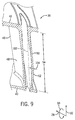
- FIG. 9 is a side section view of a nozzle 36 with a suction side 50 bulge 52.
- the dotted lines 102 in FIG. 9 represent the suction side wall 102 of a radially stacked nozzle (i.e., a similar nozzle design without a bulge 52).
- the bulge 52 protrudes from the suction side 50 in a direction transverse to the radial plane 30 extending from the rotational axis 26 out in the radial direction 32 in one direction, and in the axial direction 28 in a second direction.
- Distance 104 represents the distance the bulge protrudes from the hypothetical suction side 102 of a radially stacked nozzle without a bulge 52 at the point along the height 54 of the nozzle 36 at which the bulge 52 is at its maximum protrusion.
- the bulge 52 may begin to protrude at a position between approximately 0-20% of the height of the nozzle 36 (i.e., 0-20% of the span from the first annular wall 40 to the second annular wall 42).
- the profile of a nozzle 36 with a bulge 52 may begin to diverge from the hypothetical suction side wall 102 of a radially stacked nozzle at any point from the bottom of the nozzle 36 (i.e., where the nozzle 36 meets the first annular wall 40) to approximately 20% of the height 54 of the nozzle 36.
- the bulge 52 may begin to protrude at approximately 0%, 2%, 5%, 15%, or 20% of the height 54 of the nozzle 36, or anywhere in between.
- the bulge may begin to protrude between 1% and 15% of the height 54 of the nozzle 36, or between 5% and 10% of the height 54 of the nozzle 36.
- the bulge 52 may have a maximum protrusion 104 (i.e., the maximum deviation from the suction side wall 102 of a radially stacked nozzle) between approximately 0.5% and 10% of the height 54 of the nozzle 36.
- the maximum bulge protrusion 104 may be between approximately 0.5% and 5.0%, or between 1.0% and 4.0% of the height 54 of the nozzle 36.
- the bulge 52 may reach its maximum protrusion 104 between approximately 20% and 30% of the height 54 of the nozzle 36 (i.e., between approximately 20% and 30% of the span from the first annular wall 40 to the second annular wall 42).
- the maximum bulge protrusion may occur at approximately 20%, 22%, 24%, 26%, 28%, or 30% of the height 54 of the nozzle 36, or anywhere in between.
- the bulge 52 may reach its maximum protrusion 104 between approximately 20% and 30%, between 22% and 28%, or between 23% and 27% of the height 54 of the nozzle 36.
- the profile of a nozzle 36 with a suction side bulge 52 begins to converge with the suction side wall 102 of a radially stacked nozzle.
- the bulge 52 may end (i.e., the profile of the nozzle 36 with a suction side bulge 52 converges with the suction side wall 102 of a radially stacked nozzle) at a point between approximately 50% and 60% of the height 54 of the nozzle 36 (i.e., between approximately 50% and 60% of the span from the first annular wall 40 to the second annular wall 42).
- the bulge 52 may end at a point between approximately 52% and 58%, 53% and 57%, or 54% and 56% of the height 54 of the nozzle 36. That is, the bulge 52 may end at a point approximately 50%, 52%, 54%, 56%, 58%, or 60% of the height 54 of the nozzle 36, or anywhere in between.
- the bulge 52 may extend along the entire length of the suction side 50 in the axial direction 28, from the leading edge 44 to the trailing edge 46. In other embodiments, the bulge 52 may extend only along a portion of the suction side 50, between the leading edge 44 and the trailing edge 46.
- a last stage stator 22 populated with nozzles 36 having bulges 52 on the suction side 50 encourages root reaction, which helps to reduce secondary flows and undesirable swirling. Implementation of the disclosed techniques may increase the performance of both the last stage and the diffuser, resulting in a substantial benefit in the output of the turbomachine.
- the disclosed techniques may improve the performance of the last blade stage by approximately 200 KW or more, and may improve diffuser performance by approximately 1500 KW or more, for a total benefit of approximately 1700 KW or more. It should be understood, however, that benefits resulting from implementation of the disclosed techniques may vary from turbomachine to turbomachine.
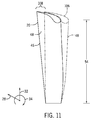
- the nozzle 36 may be tilted or angled to the pressure side 48, as compared to a radially stacked airfoil 106.
- FIG. 10 shows a schematic of nozzle 36 angled toward the pressure side 48 as compared to a radially stacked airfoil 106. That is, the nozzle 36 may have an angle of tilt 108 toward the pressure side 48 (i.e., in the circumferential direction 34) from the radial plane 30. Note that FIG. 10 is not to scale, and for the sake of clarity, may show more or less tilt 108 than may be found in some embodiments.
- the radially stacked airfoil 106 has a longitudinal axis that extends in the radial direction 32, along the radial plane 30, and may intersect with the rotational axis 26 of the turbine 16.
- the longitudinal axis 112 of the nozzle 36 may be angled toward the pressure side 48 of the nozzle 36 from the radial plane 30 by an angle 108.
- the longitudinal axis 112 of the nozzle may intersect with the radial plane 30 at a point 114 at or near the first annular wall 40, and may not intersect the rotational axis 26 of the turbine 16.
- FIG. 11 shows a perspective view of nozzle 36 with approximately 3 degrees of pressure side 48 tilt 108 as compared to a radially stacked airfoil 106. That is, the nozzle 36 may tilt 3 degrees toward the pressure side 48 (i.e., in the circumferential direction 34) from the radial plane 30.
- the tilt 108 may be anywhere between 0-5 degrees. In the embodiment shown in FIG. 11 , the pressure side 48 tilt 108 is 3 degrees. However, it should be understood that the tilt 108 may be any degree of tilt toward the pressure side 48 between 0 and 5 degrees.
- a nozzle 36 with pressure side 48 tilt 108 exerts body forces on the fluid passing through the stage 24, pushing the fluid in the radial direction toward the hub. Pushing the fluid toward the hub increases root reaction.
- a nozzle 36 with a suction side 50 bulge 52 and a pressure side 48 tilt 108 increases root reaction in the last blade stage 20, which reduces secondary flows and swirling, increasing the efficiency of the last blade stage 20, and increasing the performance of the diffuser
- a turbine nozzle disposed in a turbine includes a suction side extending between a leading edge of the nozzle and a trailing edge of the turbine nozzle in an axial direction and transverse to a longitudinal axis of the turbine nozzle, and extending a height of the nozzle in a radial direction along the longitudinal axis, a pressure side disposed opposite the suction side and extending between the leading edge of the turbine nozzle and the trailing edge of the turbine nozzle in the axial direction, and extending the height of the nozzle in the radial direction, and a bulge disposed on the suction side of the nozzle protruding relative to the other portion of the suction side in a direction transverse to a both the radial and axial directions.
- the bulge may begin at point between approximately 0% and 20% of the nozzle high, reach its maximum width at a point between approximately 20% and 40% of the nozzle height, and end at a point between approximately 50% and 60% of the nozzle height.
- the bulge may have a maximum width between approximately 0.5% and 10.0% of the nozzle height.
- the nozzle may tilt toward the pressure side when compared to a radially stacked nozzle.
- a last nozzle stage populated with nozzles having bulges on the suction side encourages root reaction, which helps to reduce secondary flows and undesirable swirling
- the disclosed techniques may improve the performance of the last blade stage by approximately 200 KW or more, and may improve diffuser performance by approximately 1500 KW or more, for a total benefit of approximately 1700 KW or more. It should be understood, however, that benefits resulting from implementation of the disclosed techniques may vary from turbomachine to turbomachine.
Landscapes
- Engineering & Computer Science (AREA)
- Mechanical Engineering (AREA)
- General Engineering & Computer Science (AREA)
- Physics & Mathematics (AREA)
- Fluid Mechanics (AREA)
- Architecture (AREA)
- Turbine Rotor Nozzle Sealing (AREA)
Applications Claiming Priority (1)
| Application Number | Priority Date | Filing Date | Title |
|---|---|---|---|
| US14/789,507 US10323528B2 (en) | 2015-07-01 | 2015-07-01 | Bulged nozzle for control of secondary flow and optimal diffuser performance |
Publications (2)
| Publication Number | Publication Date |
|---|---|
| EP3112590A1 true EP3112590A1 (fr) | 2017-01-04 |
| EP3112590B1 EP3112590B1 (fr) | 2018-06-27 |
Family
ID=56740773
Family Applications (1)
| Application Number | Title | Priority Date | Filing Date |
|---|---|---|---|
| EP16177103.5A Active EP3112590B1 (fr) | 2015-07-01 | 2016-06-30 | Buse bombée de commande de flux secondaire et performance optimale de diffuseur |
Country Status (4)
| Country | Link |
|---|---|
| US (1) | US10323528B2 (fr) |
| EP (1) | EP3112590B1 (fr) |
| JP (1) | JP6845625B2 (fr) |
| CN (1) | CN106321156A (fr) |
Families Citing this family (2)
| Publication number | Priority date | Publication date | Assignee | Title |
|---|---|---|---|---|
| US9988917B2 (en) * | 2015-10-15 | 2018-06-05 | General Electric Company | Bulged nozzle for control of secondary flow and optimal diffuser performance |
| JP6971564B2 (ja) * | 2015-12-18 | 2021-11-24 | ゼネラル・エレクトリック・カンパニイ | ターボ機械およびそのためのタービンノズル |
Citations (3)
| Publication number | Priority date | Publication date | Assignee | Title |
|---|---|---|---|---|
| EP0441097A1 (fr) * | 1990-02-07 | 1991-08-14 | United Technologies Corporation | Profil d'aile pour la section de compression d'une machine rotative |
| EP1998049A2 (fr) * | 2007-05-29 | 2008-12-03 | Rolls-Royce Deutschland Ltd & Co KG | Aube de machine de travail d'écoulement doté d'une conception à plusieurs profiles |
| EP2299124A1 (fr) * | 2009-09-04 | 2011-03-23 | Siemens Aktiengesellschaft | Aube de rotor pour un compresseur axial |
Family Cites Families (19)
| Publication number | Priority date | Publication date | Assignee | Title |
|---|---|---|---|---|
| US1475212A (en) * | 1922-07-12 | 1923-11-27 | Gen Electric | Elastic-fluid turbine |
| US2962260A (en) * | 1954-12-13 | 1960-11-29 | United Aircraft Corp | Sweep back in blading |
| US3745629A (en) * | 1972-04-12 | 1973-07-17 | Secr Defence | Method of determining optimal shapes for stator blades |
| JPH0367001A (ja) * | 1989-08-04 | 1991-03-22 | Toshiba Corp | タービンノズル |
| JP2753382B2 (ja) * | 1990-09-17 | 1998-05-20 | 株式会社日立製作所 | 軸流タービン静翼装置及び軸流タービン |
| US5326221A (en) * | 1993-08-27 | 1994-07-05 | General Electric Company | Over-cambered stage design for steam turbines |
| JP3773565B2 (ja) * | 1995-10-16 | 2006-05-10 | 株式会社東芝 | タービンノズル |
| JP3621216B2 (ja) * | 1996-12-05 | 2005-02-16 | 株式会社東芝 | タービンノズル |
| JP2000045704A (ja) * | 1998-07-31 | 2000-02-15 | Toshiba Corp | 蒸気タービン |
| JP4373629B2 (ja) * | 2001-08-31 | 2009-11-25 | 株式会社東芝 | 軸流タービン |
| US6755612B2 (en) * | 2002-09-03 | 2004-06-29 | Rolls-Royce Plc | Guide vane for a gas turbine engine |
| JP4269723B2 (ja) * | 2003-03-12 | 2009-05-27 | 株式会社Ihi | タービンノズル |
| EP1710397B1 (fr) * | 2005-03-31 | 2014-06-11 | Kabushiki Kaisha Toshiba | Aube de guidage courbée |
| US7806653B2 (en) * | 2006-12-22 | 2010-10-05 | General Electric Company | Gas turbine engines including multi-curve stator vanes and methods of assembling the same |
| US7794201B2 (en) * | 2006-12-22 | 2010-09-14 | General Electric Company | Gas turbine engines including lean stator vanes and methods of assembling the same |
| DE102011083778A1 (de) * | 2011-09-29 | 2013-04-04 | Rolls-Royce Deutschland Ltd & Co Kg | Schaufel einer Rotor- oder Statorreihe für den Einsatz in einer Strömungsmaschine |
| US8967959B2 (en) * | 2011-10-28 | 2015-03-03 | General Electric Company | Turbine of a turbomachine |
| US9255480B2 (en) | 2011-10-28 | 2016-02-09 | General Electric Company | Turbine of a turbomachine |
| US8944774B2 (en) * | 2012-01-03 | 2015-02-03 | General Electric Company | Gas turbine nozzle with a flow fence |
-
2015
- 2015-07-01 US US14/789,507 patent/US10323528B2/en active Active
-
2016
- 2016-06-22 JP JP2016123110A patent/JP6845625B2/ja not_active Expired - Fee Related
- 2016-06-30 EP EP16177103.5A patent/EP3112590B1/fr active Active
- 2016-06-30 CN CN201610514084.XA patent/CN106321156A/zh active Pending
Patent Citations (3)
| Publication number | Priority date | Publication date | Assignee | Title |
|---|---|---|---|---|
| EP0441097A1 (fr) * | 1990-02-07 | 1991-08-14 | United Technologies Corporation | Profil d'aile pour la section de compression d'une machine rotative |
| EP1998049A2 (fr) * | 2007-05-29 | 2008-12-03 | Rolls-Royce Deutschland Ltd & Co KG | Aube de machine de travail d'écoulement doté d'une conception à plusieurs profiles |
| EP2299124A1 (fr) * | 2009-09-04 | 2011-03-23 | Siemens Aktiengesellschaft | Aube de rotor pour un compresseur axial |
Also Published As
| Publication number | Publication date |
|---|---|
| JP6845625B2 (ja) | 2021-03-17 |
| JP2017015080A (ja) | 2017-01-19 |
| US20170002670A1 (en) | 2017-01-05 |
| US10323528B2 (en) | 2019-06-18 |
| EP3112590B1 (fr) | 2018-06-27 |
| CN106321156A (zh) | 2017-01-11 |
Similar Documents
| Publication | Publication Date | Title |
|---|---|---|
| CN106894847B (zh) | 涡轮机及其涡轮喷嘴 | |
| CN106948866B (zh) | 涡轮机及其涡轮叶片 | |
| US10502231B2 (en) | Diffuser pipe with vortex generators | |
| CN106894843B (zh) | 涡轮机及其涡轮叶片 | |
| US20120034064A1 (en) | Contoured axial-radial exhaust diffuser | |
| US10539032B2 (en) | Turbomachine and turbine nozzle therefor | |
| EP2645000A2 (fr) | Générateur de tourbillonnement pour chambres de combustion | |
| EP2586979B1 (fr) | Pale de turbomachine avec extrémité evasée | |
| US10633989B2 (en) | Turbomachine and turbine nozzle therefor | |
| US9988917B2 (en) | Bulged nozzle for control of secondary flow and optimal diffuser performance | |
| EP3165714A1 (fr) | Profil aérodynamique de turbine | |
| US8702384B2 (en) | Airfoil core shape for a turbomachine component | |
| EP2578815A2 (fr) | Diffuseur de gaz d'échappement | |
| EP3112590B1 (fr) | Buse bombée de commande de flux secondaire et performance optimale de diffuseur | |
| EP3168416B1 (fr) | Turbine à gaz | |
| EP3163020B1 (fr) | Cascade de pales de rotor de turbine, étage de turbine et turbine à écoulement axial | |
| US11629599B2 (en) | Turbomachine nozzle with an airfoil having a curvilinear trailing edge |
Legal Events
| Date | Code | Title | Description |
|---|---|---|---|
| PUAI | Public reference made under article 153(3) epc to a published international application that has entered the european phase |
Free format text: ORIGINAL CODE: 0009012 |
|
| AK | Designated contracting states |
Kind code of ref document: A1 Designated state(s): AL AT BE BG CH CY CZ DE DK EE ES FI FR GB GR HR HU IE IS IT LI LT LU LV MC MK MT NL NO PL PT RO RS SE SI SK SM TR |
|
| AX | Request for extension of the european patent |
Extension state: BA ME |
|
| 17P | Request for examination filed |
Effective date: 20170704 |
|
| RBV | Designated contracting states (corrected) |
Designated state(s): AL AT BE BG CH CY CZ DE DK EE ES FI FR GB GR HR HU IE IS IT LI LT LU LV MC MK MT NL NO PL PT RO RS SE SI SK SM TR |
|
| RIC1 | Information provided on ipc code assigned before grant |
Ipc: F01D 9/04 20060101ALI20180112BHEP Ipc: F01D 5/14 20060101AFI20180112BHEP |
|
| GRAP | Despatch of communication of intention to grant a patent |
Free format text: ORIGINAL CODE: EPIDOSNIGR1 |
|
| INTG | Intention to grant announced |
Effective date: 20180227 |
|
| GRAS | Grant fee paid |
Free format text: ORIGINAL CODE: EPIDOSNIGR3 |
|
| GRAA | (expected) grant |
Free format text: ORIGINAL CODE: 0009210 |
|
| AK | Designated contracting states |
Kind code of ref document: B1 Designated state(s): AL AT BE BG CH CY CZ DE DK EE ES FI FR GB GR HR HU IE IS IT LI LT LU LV MC MK MT NL NO PL PT RO RS SE SI SK SM TR |
|
| REG | Reference to a national code |
Ref country code: GB Ref legal event code: FG4D |
|
| REG | Reference to a national code |
Ref country code: AT Ref legal event code: REF Ref document number: 1012536 Country of ref document: AT Kind code of ref document: T Effective date: 20180715 |
|
| REG | Reference to a national code |
Ref country code: IE Ref legal event code: FG4D |
|
| REG | Reference to a national code |
Ref country code: DE Ref legal event code: R096 Ref document number: 602016003781 Country of ref document: DE |
|
| PG25 | Lapsed in a contracting state [announced via postgrant information from national office to epo] |
Ref country code: BG Free format text: LAPSE BECAUSE OF FAILURE TO SUBMIT A TRANSLATION OF THE DESCRIPTION OR TO PAY THE FEE WITHIN THE PRESCRIBED TIME-LIMIT Effective date: 20180927 Ref country code: LT Free format text: LAPSE BECAUSE OF FAILURE TO SUBMIT A TRANSLATION OF THE DESCRIPTION OR TO PAY THE FEE WITHIN THE PRESCRIBED TIME-LIMIT Effective date: 20180627 Ref country code: FI Free format text: LAPSE BECAUSE OF FAILURE TO SUBMIT A TRANSLATION OF THE DESCRIPTION OR TO PAY THE FEE WITHIN THE PRESCRIBED TIME-LIMIT Effective date: 20180627 Ref country code: SE Free format text: LAPSE BECAUSE OF FAILURE TO SUBMIT A TRANSLATION OF THE DESCRIPTION OR TO PAY THE FEE WITHIN THE PRESCRIBED TIME-LIMIT Effective date: 20180627 Ref country code: NO Free format text: LAPSE BECAUSE OF FAILURE TO SUBMIT A TRANSLATION OF THE DESCRIPTION OR TO PAY THE FEE WITHIN THE PRESCRIBED TIME-LIMIT Effective date: 20180927 |
|
| REG | Reference to a national code |
Ref country code: NL Ref legal event code: MP Effective date: 20180627 |
|
| REG | Reference to a national code |
Ref country code: LT Ref legal event code: MG4D |
|
| PG25 | Lapsed in a contracting state [announced via postgrant information from national office to epo] |
Ref country code: RS Free format text: LAPSE BECAUSE OF FAILURE TO SUBMIT A TRANSLATION OF THE DESCRIPTION OR TO PAY THE FEE WITHIN THE PRESCRIBED TIME-LIMIT Effective date: 20180627 Ref country code: HR Free format text: LAPSE BECAUSE OF FAILURE TO SUBMIT A TRANSLATION OF THE DESCRIPTION OR TO PAY THE FEE WITHIN THE PRESCRIBED TIME-LIMIT Effective date: 20180627 Ref country code: GR Free format text: LAPSE BECAUSE OF FAILURE TO SUBMIT A TRANSLATION OF THE DESCRIPTION OR TO PAY THE FEE WITHIN THE PRESCRIBED TIME-LIMIT Effective date: 20180928 Ref country code: LV Free format text: LAPSE BECAUSE OF FAILURE TO SUBMIT A TRANSLATION OF THE DESCRIPTION OR TO PAY THE FEE WITHIN THE PRESCRIBED TIME-LIMIT Effective date: 20180627 |
|
| REG | Reference to a national code |
Ref country code: AT Ref legal event code: MK05 Ref document number: 1012536 Country of ref document: AT Kind code of ref document: T Effective date: 20180627 |
|
| PG25 | Lapsed in a contracting state [announced via postgrant information from national office to epo] |
Ref country code: NL Free format text: LAPSE BECAUSE OF FAILURE TO SUBMIT A TRANSLATION OF THE DESCRIPTION OR TO PAY THE FEE WITHIN THE PRESCRIBED TIME-LIMIT Effective date: 20180627 |
|
| REG | Reference to a national code |
Ref country code: DE Ref legal event code: R119 Ref document number: 602016003781 Country of ref document: DE |
|
| PG25 | Lapsed in a contracting state [announced via postgrant information from national office to epo] |
Ref country code: RO Free format text: LAPSE BECAUSE OF FAILURE TO SUBMIT A TRANSLATION OF THE DESCRIPTION OR TO PAY THE FEE WITHIN THE PRESCRIBED TIME-LIMIT Effective date: 20180627 Ref country code: SK Free format text: LAPSE BECAUSE OF FAILURE TO SUBMIT A TRANSLATION OF THE DESCRIPTION OR TO PAY THE FEE WITHIN THE PRESCRIBED TIME-LIMIT Effective date: 20180627 Ref country code: CZ Free format text: LAPSE BECAUSE OF FAILURE TO SUBMIT A TRANSLATION OF THE DESCRIPTION OR TO PAY THE FEE WITHIN THE PRESCRIBED TIME-LIMIT Effective date: 20180627 Ref country code: PL Free format text: LAPSE BECAUSE OF FAILURE TO SUBMIT A TRANSLATION OF THE DESCRIPTION OR TO PAY THE FEE WITHIN THE PRESCRIBED TIME-LIMIT Effective date: 20180627 Ref country code: IS Free format text: LAPSE BECAUSE OF FAILURE TO SUBMIT A TRANSLATION OF THE DESCRIPTION OR TO PAY THE FEE WITHIN THE PRESCRIBED TIME-LIMIT Effective date: 20181027 Ref country code: EE Free format text: LAPSE BECAUSE OF FAILURE TO SUBMIT A TRANSLATION OF THE DESCRIPTION OR TO PAY THE FEE WITHIN THE PRESCRIBED TIME-LIMIT Effective date: 20180627 Ref country code: AT Free format text: LAPSE BECAUSE OF FAILURE TO SUBMIT A TRANSLATION OF THE DESCRIPTION OR TO PAY THE FEE WITHIN THE PRESCRIBED TIME-LIMIT Effective date: 20180627 |
|
| PG25 | Lapsed in a contracting state [announced via postgrant information from national office to epo] |
Ref country code: SM Free format text: LAPSE BECAUSE OF FAILURE TO SUBMIT A TRANSLATION OF THE DESCRIPTION OR TO PAY THE FEE WITHIN THE PRESCRIBED TIME-LIMIT Effective date: 20180627 Ref country code: ES Free format text: LAPSE BECAUSE OF FAILURE TO SUBMIT A TRANSLATION OF THE DESCRIPTION OR TO PAY THE FEE WITHIN THE PRESCRIBED TIME-LIMIT Effective date: 20180627 |
|
| REG | Reference to a national code |
Ref country code: BE Ref legal event code: MM Effective date: 20180630 |
|
| PG25 | Lapsed in a contracting state [announced via postgrant information from national office to epo] |
Ref country code: LU Free format text: LAPSE BECAUSE OF NON-PAYMENT OF DUE FEES Effective date: 20180630 Ref country code: MC Free format text: LAPSE BECAUSE OF FAILURE TO SUBMIT A TRANSLATION OF THE DESCRIPTION OR TO PAY THE FEE WITHIN THE PRESCRIBED TIME-LIMIT Effective date: 20180627 |
|
| REG | Reference to a national code |
Ref country code: IE Ref legal event code: MM4A |
|
| PG25 | Lapsed in a contracting state [announced via postgrant information from national office to epo] |
Ref country code: DE Free format text: LAPSE BECAUSE OF NON-PAYMENT OF DUE FEES Effective date: 20190101 Ref country code: IE Free format text: LAPSE BECAUSE OF NON-PAYMENT OF DUE FEES Effective date: 20180630 |
|
| PLBE | No opposition filed within time limit |
Free format text: ORIGINAL CODE: 0009261 |
|
| STAA | Information on the status of an ep patent application or granted ep patent |
Free format text: STATUS: NO OPPOSITION FILED WITHIN TIME LIMIT |
|
| PG25 | Lapsed in a contracting state [announced via postgrant information from national office to epo] |
Ref country code: DK Free format text: LAPSE BECAUSE OF FAILURE TO SUBMIT A TRANSLATION OF THE DESCRIPTION OR TO PAY THE FEE WITHIN THE PRESCRIBED TIME-LIMIT Effective date: 20180627 Ref country code: BE Free format text: LAPSE BECAUSE OF NON-PAYMENT OF DUE FEES Effective date: 20180630 |
|
| 26N | No opposition filed |
Effective date: 20190328 |
|
| PG25 | Lapsed in a contracting state [announced via postgrant information from national office to epo] |
Ref country code: FR Free format text: LAPSE BECAUSE OF NON-PAYMENT OF DUE FEES Effective date: 20180827 Ref country code: SI Free format text: LAPSE BECAUSE OF FAILURE TO SUBMIT A TRANSLATION OF THE DESCRIPTION OR TO PAY THE FEE WITHIN THE PRESCRIBED TIME-LIMIT Effective date: 20180627 |
|
| PG25 | Lapsed in a contracting state [announced via postgrant information from national office to epo] |
Ref country code: AL Free format text: LAPSE BECAUSE OF FAILURE TO SUBMIT A TRANSLATION OF THE DESCRIPTION OR TO PAY THE FEE WITHIN THE PRESCRIBED TIME-LIMIT Effective date: 20180627 |
|
| PG25 | Lapsed in a contracting state [announced via postgrant information from national office to epo] |
Ref country code: MT Free format text: LAPSE BECAUSE OF NON-PAYMENT OF DUE FEES Effective date: 20180630 |
|
| REG | Reference to a national code |
Ref country code: CH Ref legal event code: PL |
|
| PG25 | Lapsed in a contracting state [announced via postgrant information from national office to epo] |
Ref country code: TR Free format text: LAPSE BECAUSE OF FAILURE TO SUBMIT A TRANSLATION OF THE DESCRIPTION OR TO PAY THE FEE WITHIN THE PRESCRIBED TIME-LIMIT Effective date: 20180627 |
|
| PG25 | Lapsed in a contracting state [announced via postgrant information from national office to epo] |
Ref country code: CH Free format text: LAPSE BECAUSE OF NON-PAYMENT OF DUE FEES Effective date: 20190630 Ref country code: LI Free format text: LAPSE BECAUSE OF NON-PAYMENT OF DUE FEES Effective date: 20190630 Ref country code: PT Free format text: LAPSE BECAUSE OF FAILURE TO SUBMIT A TRANSLATION OF THE DESCRIPTION OR TO PAY THE FEE WITHIN THE PRESCRIBED TIME-LIMIT Effective date: 20180627 |
|
| PG25 | Lapsed in a contracting state [announced via postgrant information from national office to epo] |
Ref country code: HU Free format text: LAPSE BECAUSE OF FAILURE TO SUBMIT A TRANSLATION OF THE DESCRIPTION OR TO PAY THE FEE WITHIN THE PRESCRIBED TIME-LIMIT; INVALID AB INITIO Effective date: 20160630 Ref country code: MK Free format text: LAPSE BECAUSE OF NON-PAYMENT OF DUE FEES Effective date: 20180627 Ref country code: CY Free format text: LAPSE BECAUSE OF FAILURE TO SUBMIT A TRANSLATION OF THE DESCRIPTION OR TO PAY THE FEE WITHIN THE PRESCRIBED TIME-LIMIT Effective date: 20180627 |
|
| P01 | Opt-out of the competence of the unified patent court (upc) registered |
Effective date: 20230522 |
|
| REG | Reference to a national code |
Ref country code: GB Ref legal event code: 732E Free format text: REGISTERED BETWEEN 20240222 AND 20240228 |
|
| PGFP | Annual fee paid to national office [announced via postgrant information from national office to epo] |
Ref country code: GB Payment date: 20250520 Year of fee payment: 10 |
|
| PGFP | Annual fee paid to national office [announced via postgrant information from national office to epo] |
Ref country code: IT Payment date: 20250520 Year of fee payment: 10 |