EP3112670B1 - Montageverfahren für ein modulares windturbinenrotorblatt - Google Patents
Montageverfahren für ein modulares windturbinenrotorblatt Download PDFInfo
- Publication number
- EP3112670B1 EP3112670B1 EP16176261.2A EP16176261A EP3112670B1 EP 3112670 B1 EP3112670 B1 EP 3112670B1 EP 16176261 A EP16176261 A EP 16176261A EP 3112670 B1 EP3112670 B1 EP 3112670B1
- Authority
- EP
- European Patent Office
- Prior art keywords
- blade
- root section
- segment
- segments
- section
- Prior art date
- Legal status (The legal status is an assumption and is not a legal conclusion. Google has not performed a legal analysis and makes no representation as to the accuracy of the status listed.)
- Active
Links
Images








Classifications
-
- F—MECHANICAL ENGINEERING; LIGHTING; HEATING; WEAPONS; BLASTING
- F03—MACHINES OR ENGINES FOR LIQUIDS; WIND, SPRING, OR WEIGHT MOTORS; PRODUCING MECHANICAL POWER OR A REACTIVE PROPULSIVE THRUST, NOT OTHERWISE PROVIDED FOR
- F03D—WIND MOTORS
- F03D1/00—Wind motors with rotation axis substantially parallel to the air flow entering the rotor
- F03D1/06—Rotors
- F03D1/065—Rotors characterised by their construction elements
- F03D1/0675—Rotors characterised by their construction elements of the blades
-
- F—MECHANICAL ENGINEERING; LIGHTING; HEATING; WEAPONS; BLASTING
- F03—MACHINES OR ENGINES FOR LIQUIDS; WIND, SPRING, OR WEIGHT MOTORS; PRODUCING MECHANICAL POWER OR A REACTIVE PROPULSIVE THRUST, NOT OTHERWISE PROVIDED FOR
- F03D—WIND MOTORS
- F03D13/00—Assembly, mounting or commissioning of wind motors; Arrangements specially adapted for transporting wind motor components
- F03D13/10—Assembly of wind motors; Arrangements for erecting wind motors
-
- B—PERFORMING OPERATIONS; TRANSPORTING
- B23—MACHINE TOOLS; METAL-WORKING NOT OTHERWISE PROVIDED FOR
- B23P—METAL-WORKING NOT OTHERWISE PROVIDED FOR; COMBINED OPERATIONS; UNIVERSAL MACHINE TOOLS
- B23P15/00—Making specific metal objects by operations not covered by a single other subclass or a group in this subclass
- B23P15/04—Making specific metal objects by operations not covered by a single other subclass or a group in this subclass turbine or like blades from several pieces
-
- B—PERFORMING OPERATIONS; TRANSPORTING
- B29—WORKING OF PLASTICS; WORKING OF SUBSTANCES IN A PLASTIC STATE IN GENERAL
- B29C—SHAPING OR JOINING OF PLASTICS; SHAPING OF MATERIAL IN A PLASTIC STATE, NOT OTHERWISE PROVIDED FOR; AFTER-TREATMENT OF THE SHAPED PRODUCTS, e.g. REPAIRING
- B29C65/00—Joining or sealing of preformed parts, e.g. welding of plastics materials; Apparatus therefor
- B29C65/78—Means for handling the parts to be joined, e.g. for making containers or hollow articles, e.g. means for handling sheets, plates, web-like materials, tubular articles, hollow articles or elements to be joined therewith; Means for discharging the joined articles from the joining apparatus
-
- F—MECHANICAL ENGINEERING; LIGHTING; HEATING; WEAPONS; BLASTING
- F05—INDEXING SCHEMES RELATING TO ENGINES OR PUMPS IN VARIOUS SUBCLASSES OF CLASSES F01-F04
- F05B—INDEXING SCHEME RELATING TO WIND, SPRING, WEIGHT, INERTIA OR LIKE MOTORS, TO MACHINES OR ENGINES FOR LIQUIDS COVERED BY SUBCLASSES F03B, F03D AND F03G
- F05B2230/00—Manufacture
- F05B2230/50—Building or constructing in particular ways
-
- F—MECHANICAL ENGINEERING; LIGHTING; HEATING; WEAPONS; BLASTING
- F05—INDEXING SCHEMES RELATING TO ENGINES OR PUMPS IN VARIOUS SUBCLASSES OF CLASSES F01-F04
- F05B—INDEXING SCHEME RELATING TO WIND, SPRING, WEIGHT, INERTIA OR LIKE MOTORS, TO MACHINES OR ENGINES FOR LIQUIDS COVERED BY SUBCLASSES F03B, F03D AND F03G
- F05B2230/00—Manufacture
- F05B2230/60—Assembly methods
-
- F—MECHANICAL ENGINEERING; LIGHTING; HEATING; WEAPONS; BLASTING
- F05—INDEXING SCHEMES RELATING TO ENGINES OR PUMPS IN VARIOUS SUBCLASSES OF CLASSES F01-F04
- F05B—INDEXING SCHEME RELATING TO WIND, SPRING, WEIGHT, INERTIA OR LIKE MOTORS, TO MACHINES OR ENGINES FOR LIQUIDS COVERED BY SUBCLASSES F03B, F03D AND F03G
- F05B2240/00—Components
- F05B2240/20—Rotors
- F05B2240/30—Characteristics of rotor blades, i.e. of any element transforming dynamic fluid energy to or from rotational energy and being attached to a rotor
- F05B2240/302—Segmented or sectional blades
-
- F—MECHANICAL ENGINEERING; LIGHTING; HEATING; WEAPONS; BLASTING
- F05—INDEXING SCHEMES RELATING TO ENGINES OR PUMPS IN VARIOUS SUBCLASSES OF CLASSES F01-F04
- F05B—INDEXING SCHEME RELATING TO WIND, SPRING, WEIGHT, INERTIA OR LIKE MOTORS, TO MACHINES OR ENGINES FOR LIQUIDS COVERED BY SUBCLASSES F03B, F03D AND F03G
- F05B2280/00—Materials; Properties thereof
- F05B2280/40—Organic materials
- F05B2280/4007—Thermoplastics
-
- Y—GENERAL TAGGING OF NEW TECHNOLOGICAL DEVELOPMENTS; GENERAL TAGGING OF CROSS-SECTIONAL TECHNOLOGIES SPANNING OVER SEVERAL SECTIONS OF THE IPC; TECHNICAL SUBJECTS COVERED BY FORMER USPC CROSS-REFERENCE ART COLLECTIONS [XRACs] AND DIGESTS
- Y02—TECHNOLOGIES OR APPLICATIONS FOR MITIGATION OR ADAPTATION AGAINST CLIMATE CHANGE
- Y02E—REDUCTION OF GREENHOUSE GAS [GHG] EMISSIONS, RELATED TO ENERGY GENERATION, TRANSMISSION OR DISTRIBUTION
- Y02E10/00—Energy generation through renewable energy sources
- Y02E10/70—Wind energy
- Y02E10/72—Wind turbines with rotation axis in wind direction
-
- Y—GENERAL TAGGING OF NEW TECHNOLOGICAL DEVELOPMENTS; GENERAL TAGGING OF CROSS-SECTIONAL TECHNOLOGIES SPANNING OVER SEVERAL SECTIONS OF THE IPC; TECHNICAL SUBJECTS COVERED BY FORMER USPC CROSS-REFERENCE ART COLLECTIONS [XRACs] AND DIGESTS
- Y02—TECHNOLOGIES OR APPLICATIONS FOR MITIGATION OR ADAPTATION AGAINST CLIMATE CHANGE
- Y02P—CLIMATE CHANGE MITIGATION TECHNOLOGIES IN THE PRODUCTION OR PROCESSING OF GOODS
- Y02P70/00—Climate change mitigation technologies in the production process for final industrial or consumer products
- Y02P70/50—Manufacturing or production processes characterised by the final manufactured product
Definitions
- the present invention relates to a method for assembling a modular rotor blade of a wind turbine.
- Wind power is considered one of the cleanest, most environmentally friendly energy sources presently available, and wind turbines have gained increased attention in this regard.
- a modern wind turbine typically includes a tower, a generator, a gearbox, a nacelle, and a rotor having a rotatable hub with one or more rotor blades.
- the rotor blades capture kinetic energy of wind using known airfoil principles.
- the rotor blades transmit the kinetic energy in the form of rotational energy so as to turn a shaft coupling the rotor blades to a gearbox, or if a gearbox is not used, directly to the generator.
- the generator then converts the mechanical energy to electrical energy that may be deployed to a utility grid.
- the rotor blades generally include a suction side shell and a pressure side shell typically formed using molding processes that are bonded together at bond lines along the leading and trailing edges of the blade.
- the pressure and suction shells are relatively lightweight and have structural properties (e.g., stiffness, buckling resistance and strength) which are not configured to withstand the bending moments and other loads exerted on the rotor blade during operation.
- the body shell is typically reinforced using one or more structural components (e.g. opposing spar caps with a shear web configured therebetween) that engage the inner pressure and suction side surfaces of the shell halves.
- the spar caps may be constructed of various materials, including but not limited to glass fiber laminate composites and/or carbon fiber laminate composites.
- the bond lines of typical rotor blades are generally formed by applying a suitable bonding paste or compound along the bond line with a minimum designed bond width between the shell members.
- These bonding lines are a critical design constraint of the blades as a significant number of turbine blade field failures occur at the bond-line. Separation of the bond line along the leading and/or trailing edges of an operational turbine blade can result in a catastrophic failure and damage to the wind turbine.
- the methods used to manufacture the rotor blades and/or structural components thereof can be difficult to control, defect prone, and/or highly labor intensive due to handling of the dry fabrics and the challenges of infusing large laminated structures.
- conventional manufacturing methods continue to increase in complexity as the blade halves are typically manufactured using opposing mold halves that must be large enough to accommodate the entire length of the rotor blade. As such, joining the large blade halves can be highly labor intensive and more susceptible to defects.
- Rotor blades of a wind turbine are disclosed, for example, in US 2014/140855 A1 , US 2014/271217 A1 , and US 2011/103962 A1 .
- the present invention is directed to a method for assembling a modular rotor blade of a wind turbine according to claim 1.
- the present disclosure is directed to a method for assembling a modular rotor blade of a wind turbine according to claim 1.
- the method may include securing a pre-formed structural component to the blade root section in a generally span-wise direction, and mounting the plurality of blade segments to the structural component.
- the plurality of blade segments may include at least one continuous blade segment having a single joint having a pressure side surface and a suction side surface.
- the method may include separating the pressure and suction side surfaces at the single joint, mounting the continuous blade segment over the one or more spar caps, and securing the continuous blade segment between the blade root section and the blade tip section via an adhesive at the single joint.
- the step of mounting the plurality of blade segments between the blade root section and the blade tip section may further include securing the blade segments to at least one of the blade root section, the blade tip section, the structural component, the one or more spar caps, or adjacent blade segments via, for example, an adhesive, welding, one or more fasteners, or similar.
- the step of mounting the blade segments can be tailored according to the materials used for each of the blade components.
- the blade segments may be constructed of a thermoset polymer, whereas the blade root section may be constructed of a thermoplastic polymer. In such an embodiment, it may be beneficial to weld the differing materials together. In additional embodiments, it may be beneficial to mount components of a like material together via an adhesive, e.g. adjacent blade segments.
- the method may also include mounting one or more shear webs between the one or more spar caps of the blade root section or the blade tip section before, for example, the step of mounting the at least one blade segment between the blade root section and the blade tip section.
- the shear web(s) are configured to increase the rigidity in the blade root section and/or the blade tip section, thereby allowing the sections to be handled with more control.
- the blade segment(s) of certain embodiment may include at least one leading edge segment and at least one trailing edge segment.
- the method may further include mounting at least one leading edge segment and at least one trailing edge segment between the blade root section and the blade tip section, and securing the leading edge segment and the trailing edge segment together at a pressure side seam and a suction side seam.
- the method may further include supporting the blade root section via a main fixture assembly during mounting of the at least one leading edge segment and the at least one trailing segment between the blade root section and the blade tip section.
- the method may include supporting the leading and trailing edge segments during mounting via a leading edge fixture assembly and a trailing edge fixture assembly, respectively.
- the method may include placing the at least one leading edge segment onto a leading edge fixture assembly and installing the leading edge fixture assembly onto the main fixture assembly below the blade root section when the blade root section is installed onto the main fixture assembly.
- the method may also include mounting the at least one leading edge segment between the blade root section and the blade tip section while the leading edge segment is on the leading edge fixture assembly.
- the method may also include placing the at least one trailing edge segment onto a trailing edge fixture assembly and installing the trailing edge segment fixture assembly onto the main fixture assembly above the blade root section when the blade root section is installed onto the main fixture assembly.
- the method may also include installing the trailing edge fixture assembly above the blade root section, e.g. via a crane.
- the method may also include mounting the at least one trailing edge segment between the blade root section and the blade tip section while the trailing edge segment is on the trailing edge fixture assembly.
- the present disclosure is directed to a non-claimed method for assembling a modular rotor blade of a wind turbine.
- the method includes providing a pre-formed blade root section and a pre-formed blade tip section of the rotor blade.
- the blade root section includes one or more spar caps extending in a generally span-wise direction.
- the method also includes providing at least one pre-formed blade segment of the rotor blade.
- Another step includes mounting the at least one blade segment around the one or more spar caps of the blade root section, wherein the at least one blade segment comprises a chord-wise cross-section defining a continuous blade surface.
- the method also includes joining the blade tip section to at least one of the one or more spar caps or the at least one blade segment.
- the continuous blade surface may include a single joint at a trailing edge of the blade segment, wherein the continuous blade surface comprises a pressure side surface and a suction side surface.
- the method may further include separating the pressure and suction side surfaces at the single joint, mounting the continuous blade segment over the one or more spar caps, joining the pressure and suction side surfaces at the single joint, and securing the continuous blade segment between the blade root section and the blade tip section.
- the continuous blade surface may be non-jointed.
- the method may also include installing the non-joined blade surface around the one or more spar caps.
- the present disclosure is directed to a non-claimed fixture apparatus for assembling a modular rotor blade of a wind turbine.
- the fixture apparatus includes a main fixture assembly configured to support and orient a pre-formed blade root section and at least one blade segment fixture assembly configured to support and orient one or more blade segments relative to the blade root section.
- the at least one blade segment fixture assembly is configured to fit within a portion of the main fixture assembly.
- the fixture apparatus may include at least one leading edge fixture assembly and at least one trailing edge fixture assembly.
- the leading edge fixture assembly may be configured to fit below the blade root section when installed onto the main fixture assembly.
- the trailing edge fixture assembly may be configured to fit above the blade root section when installed onto the main fixture assembly. It should be understood, however, that the orientation of the fixture apparatus and thus the location of the leading and trailing fixture assemblies may be reversed.
- the main fixture assembly of the fixture apparatus may also include a blade root plate configured to align a root end portion of the blade root section.
- the main fixture assembly may also include a root support structure configured to support a root end portion of the blade root section.
- the root support structure may further include a support pad configured to support the root end portion of the blade root section.
- the present disclosure is directed to a non-claimed modular rotor blade for a wind turbine and to a method of assembling a modular rotor blade of a wind turbine according to claim 1 .
- the rotor blade includes a pre-formed blade root section, a pre-formed blade tip section, and one or more blade segments mounted between the blade root section and the blade tip section in a generally span-wise direction.
- the blade segments may include one or more leading edge segments, trailing edge segments, pressure side segments, suction side segments, a forward pressure side segment, a forward suction side segment, an aft pressure side segment, an aft suction side segment, or a non-jointed continuous blade segment.
- the blade root section and/or the blade tip section may each include one or more spar caps. Thus, the blade root section and the blade tip section may be joined together via their respective spar caps.
- the present disclosure provides many advantages not present in the prior art.
- the present disclosure provides a modular rotor blade having multiple blade segments and/or components that can each be individually pre-formed before assembly of the blade.
- the blade segments reduce the number of bond lines and shift the bond lines away from the leading and/or trailing edge regions.
- the number of scarf joints or similar can be reduced.
- the modular rotor blades as described herein may increase supply chain options, may reduce assembling cycle time, and/or may reduce shipping cost.
- the rotor blades and methods of the present disclosure provide an economic alternative to conventional rotor blades.
- the rotor blades of the present disclosure can have a reduced weight. Referring now to the drawings, FIG.
- FIG. 1 illustrates one embodiment of a wind turbine 10 according to the present disclosure.
- the wind turbine 10 includes a tower 12 with a nacelle 14 mounted thereon.
- a plurality of rotor blades 16 are mounted to a rotor hub 18, which is in turn connected to a main flange that turns a main rotor shaft.
- the wind turbine power generation and control components are housed within the nacelle 14.
- the view of FIG. 1 is provided for illustrative purposes only to place the present invention in an exemplary field of use. It should be appreciated that the invention is not limited to any particular type of wind turbine configuration.
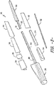
- the rotor blade 16 includes a modular configuration having a pre-formed blade root section 20, a pre-formed blade tip section 22 disposed opposite the blade root section 20, and a plurality of blade segments arranged therebetween.
- the blade root section 20 is configured to be mounted or otherwise secured to the rotor 18 ( FIG. 1 ).
- the rotor blade 16 defines a span 23 that is equal to the total length between the blade root section 20 and the blade tip section 22.
- the rotor blade 16 defines a chord 25 that is equal to the total length between a leading edge 40 of the rotor blade 16 and a trailing edge 42 of the rotor blade 16.
- the chord 25 may generally vary in length with respect to the span 23 as the rotor blade 16 extends from the blade root section 20 to the blade tip section 22.
- the blade segments may include a plurality of leading edge segments 24 and a plurality of trailing edge segments 26 generally arranged between the blade root section 20 and the blade tip section 22 along a longitudinal axis 27 in a generally span-wise direction.
- the leading and trailing edge segments 24, 26 generally serve as the outer casing/covering of the rotor blade 16 and may define a substantially aerodynamic profile, such as by defining a symmetrical or cambered airfoil-shaped cross-section.
- the blade segment portion of the blade 16 may include any combination of the segments described herein and are not limited to the embodiment as depicted.
- each of the leading edge segments 24 has a forward pressure side surface 28 and a forward suction side surface 30.
- each of the trailing edge segments 26 has an aft pressure side surface 32 and an aft suction side surface 34.
- the leading edge segment(s) 26 and the trailing edge segment(s) 26 may be joined at a pressure side seam 36 and a suction side seam 38.
- the forward pressure side surface 28 of the leading edge segment 24 and the aft pressure side surface 32 of the trailing edge segment 26 generally define a pressure side surface of the rotor blade 16.
- the forward suction side surface 30 of the leading edge segment 24 and the aft suction side surface 34 of the trailing edge segment 26 generally define a suction side surface of the rotor blade 16.
- leading edge segment(s) 24 and the trailing edge segment(s) 26 may be configured to overlap at the pressure side seam 36 and/or the suction side seam 38.
- adjacent leading edge segments 24 as well as adjacent trailing edge segments 26 may be configured to overlap at a seam 54.
- the various segments of the rotor blade 16 may be further secured together, e.g. via an adhesive 56 configured between the overlapping leading and trailing edge segments 24, 26 and/or the overlapping adjacent leading or trailing edge segments 24, 26.
- the pressure side seam 26 and/or the suction side seam 38 may be located at any suitable chord-wise location.
- the seams 36, 38 may be located from about 40% to about 60% chord from the leading edge 40 of the rotor blade 16. More specifically, in certain embodiments, the seams 36, 38 may be located at about 50% chord from the leading edge 40. In still further embodiments, the seams 36, 38 may be located less than 40% chord or greater than 60% chord from the leading edge 40 of the rotor blade 16. In addition, in some embodiments, the seams 36, 38 may be aligned as generally shown in the figures. Alternatively, the seams 36, 38 may be offset.
- the rotor blade 16 may also include at least one pressure side segment 44 and/or at least one suction side segment 46.
- the rotor blade 16 may include a pressure side segment 44 arranged and joined with a suction side segment 46 at the leading and trailing edges 40, 42.
- Such segments may be used in combination with and/or exclusive of the additional segments as described herein.
- the segments described herein are joined at two joint locations. Although, in further embodiments, less than two or more than two joint locations may be utilized.
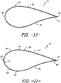
- the rotor blade 16 may also include a non-jointed, continuous blade surface 45. More specifically, as shown, the non-jointed, continuous blade surface 45 does not require bonding of multiple segments. Such segments 45 may be used in combination with and/or exclusive of the additional segments as described herein. Further, as shown in FIG. 10 , the rotor blade 16 may also include a blade segment having a single-jointed blade surface 55.
- the singlc-jointcd blade surface 55 may include a pressure side surface 33, a suction side surface 31, and a single joint 57 at the trailing edge 42.
- the single-jointed blade surface 55 only requires one joint instead of multiple joints.
- Such segments 55 may be used in combination with and/or exclusive of the additional segments as described herein.
- the rotor blade 16 may also include a multi-jointed blade surface 59. More specifically, as shown in FIG. 11 , the multi-jointed blade surface 59 may include a plurality of segments 41, 43, 47, 49 joined together via multiple joints 61, 63, 65, 67 spaced about the cross-section of the blade segment 59.
- the segments 41, 43, 47, 49 may include a forward pressure side segment 43, a forward suction side segment 41, an aft pressure side segment 49, and an aft suction side segment 47.
- FIG. 11 the multi-jointed blade surface 59 may include a plurality of segments 41, 43, 47, 49 joined together via multiple joints 61, 63, 65, 67 spaced about the cross-section of the blade segment 59.
- the segments 41, 43, 47, 49 may include a forward pressure side segment 43, a forward suction side segment 41, an aft pressure side segment 49, and an aft suction side segment 47.
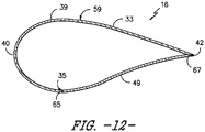
- the blade segment 59 may include a generally J-shaped blade segment 39 and an additional blade segment, e.g. aft pressure side segment 49 or aft suction side segment 47, joined together via joints 65 and 67. More specifically, as shown, the J-shaped blade segment 39 may extend from the trailing edge 42 around the suction side surface 33 to a pressure side seam 35. Such segments may be used in combination with and/or exclusive of the additional segments as described herein.
- the rotor blade 16 may also include one or more longitudinally extending spar caps configured to provide increased stiffness, buckling resistance and/or strength to the rotor blade 16.
- the blade root section 20 may include one or more longitudinally extending spar caps 48, 50 configured to be engaged against the opposing inner surfaces of the blade segments of the rotor blade 16.
- the blade tip section 22 may include one or more longitudinally extending spar caps 51, 53 configured to be engaged against the opposing inner surfaces of the blade of the rotor blade 16.
- blade tip section 22 and/or the blade root section 20 may also include one or more shear webs 35 configured between the one or more spar caps 48, 50, 51, 53 of the blade root section 20 or the blade tip section 22, respectively.
- the shear web(s) 35 are configured to increase the rigidity in the blade root section 20 and/or the blade tip section 22, thereby allowing the sections 20, 22 to be handled with more control.
- the blade root section 20 and/or the blade tip section 22 may be pre-formed with the one or more spar caps 48, 50, 51, 53.
- the blade root spar caps 48, 50 may be configured to align with the blade tip spar caps 51, 53.
- the spar caps 48, 50, 51, 53 may generally be designed to control the bending stresses and/or other loads acting on the rotor blade 16 in a generally span-wise direction (a direction parallel to the span 23 of the rotor blade 16) during operation of a wind turbine 10.
- the spar caps 48, 50, 51, 53 may be designed to withstand the span-wise compression occurring during operation of the wind turbine 10.
- the spar cap(s) 48, 50, 51, 53 may be configured to extend from the blade root section 20 to the blade tip section 22 or a portion thereof.
- the blade root section 20 and the blade tip section 22 may be joined together via their respective spar caps 48, 50, 51, 53.
- the rotor blade 16 may also include an additional structural component 52 secured to the blade root section 20 and extending in a generally span-wise direction. More specifically, the structural component 52 may extend any suitable distance between the blade root section 20 and the blade tip section 22. Thus, the structural component 52 is configured to provide additional structural support for the rotor blade 16 as well as an optional mounting structure for the various blade segments as described herein. For example, in certain embodiments, the structural component 52 may be secured to the blade root section 20 and may extend a predetermined span-wise distance such that the leading and/or trailing edge segments 24, 26 can be mounted thereto.
- the method 100 includes providing a pre-formed a blade root section 20 and a pre-formed blade tip section 22 of the rotor blade.
- the blade root section 20 and optionally the blade tip section 22 each include one or more spar caps 48, 50, 51, 53 extending in a generally span-wise direction.
- the blade root section 20 and the spar caps 48, 50 are manufactured (e.g. infused) in a single shot or mold so as to produce a uniform, integral part.
- the blade tip section 22 and the one or more spar caps 51, 53 may be in a single shot so as to produce a uniform, integral part.
- the method 100 may also include providing at least one pre-formed blade segment (e.g. segments 24, 26, 41, 43, 44, 45, 46, 47, or 49 as described herein) of the rotor blade 16. Further, as shown at 106, the method 100 also includes mounting one or more blade segments around the spar caps 48, 50 of the blade root section 20. More specifically, according to the invention, the blade segment(s) have a chord-wise cross-section having multiple joints, with at least one of the multiple joints being located on either the pressure side surface or the suction side surface of the blade segment. Thus, in certain embodiments, the method 100 may include mounting leading and trailing edge segments 24, 26 between the blade root section 20 and the blade tip section 22 and joining the segments via the pressure and suction side seams 36, 38.
- pre-formed blade segment e.g. segments 24, 26, 41, 43, 44, 45, 46, 47, or 49 as described herein
- the method 100 also includes mounting one or more blade segments around the spar caps 48, 50 of the blade root section 20. More specifically, according to the invention,
- the method 100 may include mounting at least one pressure side segment 44 and at least one suction side segment 46 between the blade root section 20 and the blade tip section 22 in a generally span-wise direction.
- the method 100 may include separating the pressure and suction side surfaces 31, 33 at the single joint 57, mounting the continuous blade segment 55 over the one or more spar caps 48, 50, and securing the continuous blade segment 55 between the blade root section 20 and the blade tip section 22 via an adhesive at the single joint 55.
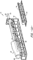
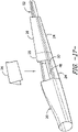
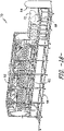
- a fixture apparatus 70 may be used to assemble the rotor blade 16. More specifically, the fixture apparatus 70 may be used to arrange and/or orient the blade segments of the rotor blade 16 such that the segments can be properly mounted between the blade root section 20 and the blade tip section 22. More specifically, as shown, the fixture apparatus 70 may include a main fixture assembly 58 that is configured to support and orient the blade root section 20, e.g. with the leading edge side down or vice versa. Further, in some embodiments, the main fixture assembly 58 may also include a blade root plate 64 configured to align a root end portion 68 of the blade root section 20 on the main fixture assembly 58.
- the main fixture assembly 58 may also include a root support structure 66 configured to support the root end portion 68 of the blade root section 20.
- the root support structure 66 may further include a support pad 72 configured to provide further support and/or protection to the root end portion 68 of the blade root section 20.
- the fixture apparatus may include a leading edge fixture assembly 60 that is configured to support and/or orient the leading edge segment(s) 24 relative to the blade root section 20.
- the leading edge fixture assembly 60 may be installed onto the main fixture assembly 58, e.g. below the blade root section 20 when the blade root section 20 is installed onto the main fixture assembly 58.
- the leading edge fixture assembly 60 allows the leading edge segment(s) 24 to be easily mounted between the blade root section 20 and the blade tip section 22 while the leading edge segment(s) 24 are held in place via the leading edge fixture assembly 60.
- the fixture apparatus 70 may also include a trailing edge fixture assembly 62 that is configured to support and/or orient the trailing edge segment(s) 26 relative to the blade root section 20.
- the trailing edge segment(s) 26 can be loaded onto the trailing edge fixture assembly 62 and the fixture assembly 62 can be installed onto the main fixture assembly 58, e.g. above the blade root section 20 when the blade root section 20 is installed onto the main fixture assembly 58.
- the trailing edge fixture assembly 62 containing the trailing edge segment(s) 26 may be installed onto the main fixture assembly 58 above the blade root section 20 via a crane.
- each of the fixture assemblies 58, 60, 62 may be used to support and arrange the various blade components/segments in a generally span-wise direction such that the components may be easily aligned and secured together to form the rotor blade 16.
- leading edge segment(s) 24 may be loaded onto and supported by the leading edge fixture assembly 60. Further, in particular embodiments, the leading edge segment(s) 24 may be joined together, e.g. via an adhesive, while being supported on the leading edge fixture assembly 60.
- the leading edge fixture assembly 60 may be loaded onto the main fixture assembly 58, e.g. in a lower portion of the main fixture assembly 58.
- the leading edge fixture assembly 60 may be lifted to the blade root section 20 so as to properly locate the leading edge segment(s) 24 relative to the blade root section 20.
- the trailing edge segment(s) 26 may be loaded onto the trailing edge fixture assembly 62.
- one or more adjacent trailing edge segment(s) 26 may be joined together, e.g. via an adhesive, while being supported by the trailing edge fixture assembly 62.
- the trailing edge fixture assembly 62 may be lowered onto the main fixture assembly 58, e.g. using a crane, such that one or more of the trailing edge segment(s) 26 may be properly oriented relative to the leading edge segment(s) 24.
- the method 100 may also include securing an additional structural component 52 to the blade root section 20 such that the structural component 52 extends in a generally span-wise direction.
- the blade segments e.g. the leading and trailing edge segments 24, 26
- the trailing edges segments 26 may be mounted to the structural component 52 of the blade root section 20 and the leading edge segments 24 may be mounted to the trailing edge segments 26, e.g. by overlapping the trailing edge segments 26 at seams 36, 38.
- any of the blade segments as described herein may be similarly mounted to the structural component 52 of the blade root section 20 in a span-wise direction.
- the method 100 may also include joining the blade tip section 20 to either or both of the spar caps 51, 53 and/or one of the blade segments so as to form the modular rotor blade 16, as shown in FIG. 19(A) and (B) .
- the method 100 may also include mounting one or more shear webs 35 between the one or more spar caps 48, 50, 51, 53 of the blade root section 20 or the blade tip section 22 before, for example, the step of mounting the at least one blade segment between the blade root section 20 and the blade tip section 22.
- the shear web(s) are configured to increase the rigidity in the blade root section 20 and/or the blade tip section 22.
- the remaining closeout segments e.g. pressure and suction side segments 44 and 46
- the remaining closeout segments may be installed over the tip-root connection to complete the rotor blade 16, e.g. as shown in FIG. 19(C) .
Landscapes
- Engineering & Computer Science (AREA)
- Mechanical Engineering (AREA)
- Life Sciences & Earth Sciences (AREA)
- Sustainable Development (AREA)
- Sustainable Energy (AREA)
- Chemical & Material Sciences (AREA)
- Combustion & Propulsion (AREA)
- General Engineering & Computer Science (AREA)
- Wind Motors (AREA)
- Turbine Rotor Nozzle Sealing (AREA)
Claims (8)
- Ein Verfahren (100) zum Zusammenbauen eines modularen Rotorblattes (16) einer Windturbine (10), wobei das Verfahren Folgendes umfasst:Bereitstellen (102) eines vorgeformten Blattwurzelabschnitts (20) und eines vorgeformten Blattspitzenabschnitts (22) des Rotorblattes (16), wobei der Blattwurzelabschnitt (20) einen oder mehrere Holmgurte (48, 50) hat, die sich in einer im Allgemeinen Spannweitenrichtung davon erstrecken, wobei der vorgeformte Blattwurzelabschnitt einstückig mit dem einen oder den mehreren Holgurten (48, 50) in einem einzelnen Spritzvorgang oder in einer einzelnen Form hergestellt wird;Bereitstellen (104) von einer Vielzahl von vorgeformten Blattsegmenten (24, 26) des Rotorblattes (16);Montieren (106) der Vielzahl von Blattsegmenten (24, 26) um den einen oder die mehreren Holmgurte (48, 50) des Blattwurzelabschnitts (20) zwischen dem Blattwurzelabschnitt (20) und dem Blattspitzenabschnitt (22), wobei, bei einer Montage um den einen oder die mehreren Holmgurte (48, 50) mindestens eines von der Vielzahl von Blattsegmenten (24, 26) einen Querschnitt in Sehnenrichtung mit mehreren Verbindungsstellen (61, 65, 67) umfasst, die das jeweilige Blattsegment (24, 26) mit mindestens einem anderen von der Vielzahl von Blattsegmenten (24, 26) verbindet, wobei mindestens eine von den Verbindungsstellen (61, 65, 67) an mindestens einer von einer Druckseitenfläche (31) oder einer Saugseitenfläche (33) angeordnet ist; undVerbinden (108) des Blattspitzenabschnitts (22) mit mindestens einem von dem einen oder mehreren Holmgurten (48, 50) oder der Vielzahl von Blattsegmenten (24, 26).
- Das Verfahren (100) von Anspruch 1, weiterhin umfassend:Befestigen einer vorgeformten Strukturkomponente (52) an dem Blattwurzelabschnitt (20) in einer im Allgemeinen Spannweitenrichtung, undMontieren der Vielzahl von Blattsegmenten (24, 26) an der Strukturkomponente (52).
- Das Verfahren (100) von Anspruch 1 oder Anspruch 2, wobei das Montieren der Vielzahl von Blattsegmenten (24, 26) ferner das Befestigen der Blattsegmente (24, 26) an mindestens einem von dem Blattwurzelabschnitt (20), dem Blattspitzenabschnitt (22), der Strukturkomponente (52), dem einen oder den mehreren Holmgurten (48, 50) oder angrenzenden Blattsegmenten über mindestens eines von Klebstoff, Schweißen oder einem oder mehreren Befestigungselementen.
- Das Verfahren (100) von einem der vorhergehenden Ansprüche, ferner umfassend das Montieren von einem oder mehreren Scherstegen (35) zwischen dem einen oder den mehreren Holmgurten (48, 50) des Blattwurzelabschnitts (20) oder von einem oder mehreren Holmgurten des Blattspitzenabschnitts (22) vor der Montage des mindestens einen Blattsegments zwischen dem Blattwurzelabschnitt (20) und dem Blattspitzenabschnitt (22).
- Das Verfahren (100) von einem der vorhergehenden Ansprüche, weiterhin umfassend:Montieren von mindestens einem Vorderkantensegment (24) und mindestens einem Hinterkantensegment (26) zwischen dem Blattwurzelabschnitt (20) und dem Blattspitzenabschnitt (22), undBefestigen des Vorderkantensegments (24) und des Hinterkantensegments (26) an einer Druckseitennaht (36) und einer Saugseitennaht (38).
- Das Verfahren (100) von Anspruch 5, weiterhin umfassend:Stützen des Blattwurzelabschnitts (20) über eine Hauptbefestigungsanordnung (58) während der Montage des mindestens einen Vorderkantensegments (24) und des mindestens einen Hinterkantensegments (26) zwischen dem Blattwurzelabschnitt (20) und der Blattspitzenabschnitt (22), undStützen der mindestens einen Vorder- und Hinterkantensegmente (24, 26) während der Montage über eine Vorderkantenbefestigungsanordnung (60) bzw. eine Hinterkantenbefestigungsanordnung (62).
- Das Verfahren (100) von Anspruch 6, weiterhin umfassend:Platzieren des mindestens einen Vorderkantensegments (24) auf einer Vorderkantenbefestigungsanordnung (60),Installieren der Vorderkantenbefestigungsanordnung (60) auf der Hauptbefestigungsanordnung (58) unterhalb des Blattwurzelabschnitts (20), wenn der Blattwurzelabschnitt (20) auf der Hauptbefestigungsanordnung (58) installiert ist, undMontieren des mindestens einen Vorderkantensegments (24) zwischen dem Blattwurzelabschnitt (20) und dem Blattspitzenabschnitt (22), während sich das Vorderkantensegment (24) auf der Vorderkantenbefestigungsanordnung (60) befindet.
- Das Verfahren (100) von Anspruch 6 oder Anspruch 7, weiterhin umfassend:Platzieren des mindestens einen Hinterkantensegments (26) auf der Hinterkantenbefestigungsanordnung (62),Installieren der Hinterkantenbefestigungsanordnung (62) auf der Hauptbefestigungsanordnung (58) über dem Blattwurzelabschnitt (20), wenn der Blattwurzelabschnitt (20) auf der Hauptbefestigungsanordnung (58) installiert ist, undMontieren des mindestens einen Hinterkantensegments (26) zwischen dem Blattwurzelabschnitt (20) und dem Blattspitzenabschnitt (22), während sich das Hinterkantensegment (26) auf der Hinterkantenbefestigungsanordnung (62) befindet.
Applications Claiming Priority (1)
| Application Number | Priority Date | Filing Date | Title |
|---|---|---|---|
| US14/753,142 US9897065B2 (en) | 2015-06-29 | 2015-06-29 | Modular wind turbine rotor blades and methods of assembling same |
Publications (2)
| Publication Number | Publication Date |
|---|---|
| EP3112670A1 EP3112670A1 (de) | 2017-01-04 |
| EP3112670B1 true EP3112670B1 (de) | 2022-07-27 |
Family
ID=56235729
Family Applications (1)
| Application Number | Title | Priority Date | Filing Date |
|---|---|---|---|
| EP16176261.2A Active EP3112670B1 (de) | 2015-06-29 | 2016-06-24 | Montageverfahren für ein modulares windturbinenrotorblatt |
Country Status (6)
| Country | Link |
|---|---|
| US (1) | US9897065B2 (de) |
| EP (1) | EP3112670B1 (de) |
| CN (1) | CN106286118B (de) |
| BR (1) | BR102016014944B1 (de) |
| DK (1) | DK3112670T3 (de) |
| ES (1) | ES2924758T3 (de) |
Families Citing this family (14)
| Publication number | Priority date | Publication date | Assignee | Title |
|---|---|---|---|---|
| EP2963282B1 (de) * | 2014-07-04 | 2018-10-24 | Siemens Aktiengesellschaft | Montierringanordnug für das Blatt einer Windturbine |
| CN110944829B (zh) * | 2017-06-06 | 2021-12-21 | 维斯塔斯风力系统有限公司 | 风轮机叶片制造方面的改进 |
| US10738497B1 (en) | 2017-10-31 | 2020-08-11 | Pecos Wind Power, Inc. | Nested wind tower assembly |
| EP3788251B1 (de) * | 2018-05-03 | 2025-12-03 | General Electric Renovables España, S.L. | Verbesserte verbindungsanordnung für eine segmentierte windturbinenrotorschaufel |
| US11236733B2 (en) * | 2018-09-17 | 2022-02-01 | General Electric Company | Heating system and method for a jointed wind rotor turbine blade |
| AU2020232943A1 (en) * | 2019-03-01 | 2021-09-23 | General Electric Renovables España, S.L. | Jointed wind turbine rotor blade with chord-wise extending pin bushings designed to minimize chord-wise gap |
| DK3966446T3 (da) * | 2019-05-10 | 2025-04-07 | Blade Dynamics Ltd | Fremgangsmåde og system til fremstilling af en vindmøllevinge |
| CN110645142B (zh) * | 2019-09-27 | 2023-09-22 | 明阳智慧能源集团股份公司 | 一种全生命周期内不报废的模块化风电叶片及其制造方法 |
| CN110578654B (zh) * | 2019-10-08 | 2021-01-22 | 中材科技风电叶片股份有限公司 | 叶片成型方法以及叶片 |
| ES2974710T3 (es) * | 2019-12-17 | 2024-07-01 | Vestas Wind Sys As | Pala de aerogenerador |
| EP4066987A1 (de) * | 2021-04-01 | 2022-10-05 | Siemens Gamesa Renewable Energy A/S | Verfahren zur herstellung einer windturbinenschaufel |
| EP4174310B1 (de) * | 2021-10-27 | 2026-03-25 | LM Wind Power A/S | Segmentiertes windturbinenrotorblatt |
| EP4642624A1 (de) * | 2022-12-27 | 2025-11-05 | LM Wind Power A/S | Rotorblattform und verfahren zur herstellung eines rotorblatts damit |
| GB2627440A (en) * | 2023-02-20 | 2024-08-28 | Dfm Blades Ltd | Method of manufacturing a spar structure, a spar structure for a wind blade, a wind blade, and an apparatus for manufacturing a spar structure |
Citations (1)
| Publication number | Priority date | Publication date | Assignee | Title |
|---|---|---|---|---|
| US20140271217A1 (en) * | 2013-03-15 | 2014-09-18 | Modular Wind Energy, Inc. | Efficient wind turbine blade design and associated manufacturing methods using rectangular spars and segmented shear web |
Family Cites Families (137)
| Publication number | Priority date | Publication date | Assignee | Title |
|---|---|---|---|---|
| US2884078A (en) | 1953-10-21 | 1959-04-28 | Parsons Corp | Rotor blade structure having spanwise reinforcing members |
| US4329119A (en) | 1977-08-02 | 1982-05-11 | The Boeing Company | Rotor blade internal damper |
| US4474536A (en) | 1980-04-09 | 1984-10-02 | Gougeon Brothers, Inc. | Wind turbine blade joint assembly and method of making wind turbine blades |
| AT398064B (de) | 1992-07-01 | 1994-09-26 | Hoac Austria Flugzeugwerk Wr N | Kunststoff-verbundprofil, insbesondere flügelholm für den flugzeugbau |
| FR2760681B1 (fr) | 1997-03-12 | 1999-05-14 | Alternatives En | Procede de fabrication d'une piece de grandes dimensions en materiau composite et pale d'helice, en particulier d'eolienne, fabriquee selon ce procede |
| JP3930200B2 (ja) | 1998-10-06 | 2007-06-13 | 三菱重工業株式会社 | 風力発電翼の製造方法 |
| JP2002137307A (ja) | 2000-11-02 | 2002-05-14 | Toray Ind Inc | 繊維強化樹脂製風車ブレード構造体 |
| CN1975152B (zh) | 2001-07-19 | 2012-03-21 | 维斯塔斯风力系统集团公司 | 风力涡轮机叶片 |
| DK176335B1 (da) | 2001-11-13 | 2007-08-20 | Siemens Wind Power As | Fremgangsmåde til fremstilling af vindmöllevinger |
| DE10214340C1 (de) | 2002-03-28 | 2003-11-27 | Aerodyn Eng Gmbh | Blattanschluß für die Rotorblätter einer Windenergieanlage und Verfahren zu dessen Herstellung |
| WO2004076852A2 (en) | 2003-02-28 | 2004-09-10 | Vestas Wind Systems A/S | Method of manufacturing a wind turbine blade, wind turbine blade, front cover and use of a front cover |
| CA2517951C (en) | 2003-03-06 | 2008-08-05 | Vestas Wind Systems A/S | Pre-form and method of preparing a pre-form |
| EP1486415A1 (de) | 2003-06-12 | 2004-12-15 | SSP Technology A/S | Windturbinenflügel und Verfahren zur Herstellung einer Turbinenflügelwurzel |
| DE10336461A1 (de) | 2003-08-05 | 2005-03-03 | Aloys Wobben | Verfahren zur Herstellung eines Rotorblattes einer Windenergieanlage |
| EP2770197A3 (de) | 2003-09-29 | 2014-09-17 | Vestas Wind Systems A/S | Windturbinenschaufel, Windturbine, Verfahren zur Bereitstellung von Blitzableitermitteln an einer Windturbinenschaufel und Verwendung davon |
| DE602004004371T2 (de) | 2004-05-11 | 2007-05-16 | Hexcel Holding Gmbh | Prepregs zum Gebrauch im Aufbau von Schichten von Verbundwerkstoffen und Verfahren zu deren Aufbereitung |
| ATE534817T1 (de) | 2004-06-30 | 2011-12-15 | Vestas Wind Sys As | Aus zwei getrennten teilen hergestellte windturbinenflügel |
| ES2249182B1 (es) | 2004-09-14 | 2007-05-01 | Gamesa Eolica S.A. | Viga estructural de la pala de un aerogenerador eolico y proceso de fabricacion de la misma. |
| JP4691565B2 (ja) | 2004-12-29 | 2011-06-01 | ヴェスタス ウィンド システムズ アー/エス | 固定部材を有する風力タービンブレードシェル部材を製造する方法および固定部材を有する風力タービンブレード |
| DK176564B1 (da) | 2004-12-29 | 2008-09-01 | Lm Glasfiber As | Fiberforstærket samling |
| CN101137841B (zh) | 2005-02-03 | 2013-01-09 | 维斯塔斯风力系统有限公司 | 制造风轮机叶片壳体构件的方法 |
| EP1856408B1 (de) | 2005-02-22 | 2017-04-05 | Vestas Wind Systems A/S | Windturbinenblatt |
| ES2265760B1 (es) | 2005-03-31 | 2008-01-16 | GAMESA INNOVATION & TECHNOLOGY, S.L. | Pala para generadores eolicos. |
| CN101263277B (zh) | 2005-07-15 | 2011-11-30 | 维斯塔斯风力系统有限公司 | 风轮机叶片 |
| US7637721B2 (en) | 2005-07-29 | 2009-12-29 | General Electric Company | Methods and apparatus for producing wind energy with reduced wind turbine noise |
| JP2007092716A (ja) | 2005-09-30 | 2007-04-12 | Toray Ind Inc | 翼構造体およびその製造方法 |
| WO2007051465A1 (en) | 2005-11-03 | 2007-05-10 | Vestas Wind Systems A/S | A wind turbine blade comprising one or more oscillation dampers |
| US7517198B2 (en) | 2006-03-20 | 2009-04-14 | Modular Wind Energy, Inc. | Lightweight composite truss wind turbine blade |
| US7654799B2 (en) | 2006-04-30 | 2010-02-02 | General Electric Company | Modular rotor blade for a wind turbine and method for assembling same |
| JP4969363B2 (ja) | 2006-08-07 | 2012-07-04 | 東レ株式会社 | プリプレグおよび炭素繊維強化複合材料 |
| ES2392187T3 (es) | 2006-11-23 | 2012-12-05 | Siemens Aktiengesellschaft | Método para fabricar un material laminado reforzado con fibra, uso de este material laminado, pala de turbina eólica y turbina eólica que comprende este material laminado |
| DK2104785T3 (da) | 2007-01-16 | 2014-10-13 | Bladena Aps | Forstærket vindturbineblad |
| ES2342638B1 (es) | 2007-02-28 | 2011-05-13 | GAMESA INNOVATION & TECHNOLOGY, S.L. | Una pala de aerogenerador multi-panel. |
| GB2447964B (en) | 2007-03-29 | 2012-07-18 | Gurit Uk Ltd | Moulding material |
| GB2464539B (en) | 2008-10-20 | 2014-01-08 | Hexcel Composites Ltd | Composite Materials with Improved Sandability |
| GB0717690D0 (en) * | 2007-09-11 | 2007-10-17 | Blade Dynamics Ltd | Wind turbine blade |
| US20090070977A1 (en) | 2007-09-13 | 2009-03-19 | General Electric Company | Jig And Fixture For Wind Turbine Blade |
| GB2455045B (en) | 2007-10-08 | 2010-01-06 | Gurit | Production of closed cell foam body |
| ES2372440T3 (es) | 2007-11-09 | 2012-01-19 | Vestas Wind Systems A/S | Procedimiento para fabricar una pala de aerogenerador y uso de una esterilla estructural para reforzar una estructura de pala de aerogenerador. |
| US20090148300A1 (en) | 2007-12-10 | 2009-06-11 | General Electric Company | Modular wind turbine blades with resistance heated bonds |
| US7740453B2 (en) * | 2007-12-19 | 2010-06-22 | General Electric Company | Multi-segment wind turbine blade and method for assembling the same |
| CN101462358B (zh) | 2007-12-19 | 2013-09-11 | 维斯塔斯风力系统有限公司 | 一种制备预成型件的设备 |
| CN101462316A (zh) | 2007-12-19 | 2009-06-24 | 维斯塔斯风力系统有限公司 | 预成型件的制备方法 |
| CN201155423Y (zh) | 2008-02-15 | 2008-11-26 | 无锡瑞尔竹风科技有限公司 | 竹制复合材料风力发电机叶片 |
| US8114329B2 (en) | 2008-03-03 | 2012-02-14 | Abe Karem | Wing and blade structure using pultruded composites |
| US8747098B1 (en) | 2008-03-24 | 2014-06-10 | Ebert Composites Corporation | Thermoplastic pultrusion die system and method |
| GB2450196B (en) | 2008-03-27 | 2009-08-26 | Gurit | Composite materials |
| JP2009235306A (ja) | 2008-03-28 | 2009-10-15 | Sekisui Film Kk | 補強用プリプレグシート及び構造体の補強方法 |
| GB0805713D0 (en) | 2008-03-28 | 2008-04-30 | Blade Dynamics Ltd | A wind turbine blade |
| CN101302302B (zh) | 2008-04-21 | 2011-02-23 | 威海光威复合材料有限公司 | 风力发电机叶片用半预浸料及其生产方法 |
| GB0807515D0 (en) | 2008-04-24 | 2008-06-04 | Blade Dynamics Ltd | A wind turbine blade |
| DE602008004313D1 (de) | 2008-04-29 | 2011-02-17 | Siemens Ag | Verfahren zur Herstellung eines faserverstärkten Laminats eines seitlich ausgedehnten Materials, das in eine Seitenrichtung steifer ist als in eine zweite Steinrichtung |
| ES2385516B1 (es) | 2008-06-27 | 2013-05-31 | Gamesa Innovation & Technology, S.L. | Inserto de pala y método de colocación del mismo. |
| GB2451192B (en) | 2008-07-18 | 2011-03-09 | Vestas Wind Sys As | Wind turbine blade |
| GB2462308A (en) | 2008-08-01 | 2010-02-03 | Vestas Wind Sys As | Extension portion for wind turbine blade |
| GB2463250A (en) | 2008-09-04 | 2010-03-10 | Vestas Wind Sys As | A wind turbine blade formed from welded thermoplastic sections |
| US20100098549A1 (en) | 2008-10-16 | 2010-04-22 | Gabriel Mironov | Wind Turbine Blade |
| KR100980043B1 (ko) | 2008-10-22 | 2010-09-06 | 한국전력기술 주식회사 | Fpga를 이용한 발전소 보호 시스템 및 보호 방법 |
| WO2010057502A2 (en) | 2008-11-24 | 2010-05-27 | Vestas Wind Systems A/S | Wind turbine blade comprising particle-reinforced bonding material |
| CN102308083B (zh) | 2008-12-05 | 2016-04-13 | 模组风能公司 | 高效风轮机叶片 |
| EP2379312B1 (de) | 2009-01-21 | 2019-04-03 | Vestas Wind Systems A/S | Verfahren zur herstellung einer windturbinenschaufel und vorform für eine windturbinenschaufel |
| CN201376388Y (zh) | 2009-01-23 | 2010-01-06 | 维斯塔斯风力系统有限公司 | 预成型件以及包括增强结构的翼梁 |
| DE102009001806A1 (de) | 2009-03-24 | 2010-09-30 | Evonik Degussa Gmbh | Prepregs und daraus bei niedriger Temperatur hergestellte Formkörper |
| EP2416950B1 (de) | 2009-04-10 | 2013-09-25 | XEMC Darwind B.V. | Geschützte windturbinenschaufel, herstellungsverfahren dafür und windturbine |
| GB0907011D0 (en) | 2009-04-23 | 2009-06-03 | Vestas Wind Sys As | Incorporation of functional cloth into prepeg composites |
| US7854594B2 (en) * | 2009-04-28 | 2010-12-21 | General Electric Company | Segmented wind turbine blade |
| EP2253836A1 (de) | 2009-05-18 | 2010-11-24 | Lm Glasfiber A/S | Windturbinenblatt |
| EP2255957B1 (de) | 2009-05-25 | 2013-07-10 | LM WP Patent Holding A/S | Verfahren zur Herstellung einer Verbundstruktur mit einem vorgefertigten Verstärkungselement |
| CN101906251B (zh) | 2009-06-04 | 2013-06-12 | 上海杰事杰新材料(集团)股份有限公司 | 一种风力发电机叶片用复合材料及其制备方法 |
| JP2011032987A (ja) | 2009-08-05 | 2011-02-17 | Nitto Denko Corp | 風力発電機ブレード用補強シート、風力発電機ブレードの補強構造、風力発電機および風力発電機ブレードの補強方法 |
| EP2283996A1 (de) | 2009-08-13 | 2011-02-16 | Siemens Aktiengesellschaft | Verfahren und Anordnung zur Herstellung einer Windturbinenschaufel |
| DK2295235T3 (da) | 2009-08-20 | 2013-07-29 | Siemens Ag | Fiberforstærket plaststruktur og fremgangsmåde til fremstilling af den fiberforstærkede plaststruktur |
| US8657581B2 (en) | 2009-08-28 | 2014-02-25 | Gordon Holdings, Inc. | Thermoplastic rotor blade |
| CN102022254B (zh) | 2009-09-23 | 2014-12-17 | 固瑞特模具(太仓)有限公司 | 风轮机叶片及其生产方法 |
| US8673106B1 (en) | 2009-11-13 | 2014-03-18 | Bounce Composites, LLC | Methods and apparatus for forming molded thermal plastic polymer components |
| GB2475352B8 (en) | 2009-12-14 | 2012-10-03 | Gurit Ltd | Repair of composite materials. |
| CA2784256A1 (en) | 2009-12-18 | 2011-06-23 | Magna International Inc. | Sheet molding compound with cores |
| EP2338668A1 (de) | 2009-12-22 | 2011-06-29 | Lm Glasfiber A/S | Verfahren zur Herstellung einer Verbundschalenstruktur |
| MX341495B (es) | 2010-01-14 | 2016-08-23 | Neptco Inc * | Componentes de pala de rotor de turbina eolica y metodos para la fabricacion de los mismos. |
| DK2526288T3 (da) | 2010-01-21 | 2017-08-21 | Vestas Wind Sys As | Segmenteret rotorvingeforlængelsesdel |
| GB201002249D0 (en) | 2010-02-10 | 2010-03-31 | Walters Albert E D | Improvements in or relating to methods of manufacture |
| DE202010000323U1 (de) | 2010-03-05 | 2011-06-22 | Lätzsch GmbH Kunststoffverarbeitung, 04567 | Windflügel für eine Strömungsenergieanlage |
| WO2011113812A1 (en) | 2010-03-15 | 2011-09-22 | Vestas Wind Systems A/S | Improved wind turbine blade spar |
| US8192169B2 (en) | 2010-04-09 | 2012-06-05 | Frederick W Piasecki | Highly reliable, low cost wind turbine rotor blade |
| CA2795982C (en) | 2010-04-12 | 2017-10-24 | Siemens Aktiengesellschaft | Fixation of a heating mat to a blade of a wind turbine |
| US20130022466A1 (en) | 2010-04-12 | 2013-01-24 | Hans Laurberg | Controlling of a heating mat on a blade of a wind turbine |
| GB201007336D0 (en) | 2010-04-30 | 2010-06-16 | Blade Dynamics Ltd | A modular structural composite beam |
| US9500179B2 (en) | 2010-05-24 | 2016-11-22 | Vestas Wind Systems A/S | Segmented wind turbine blades with truss connection regions, and associated systems and methods |
| EP2400147A1 (de) | 2010-06-25 | 2011-12-28 | Siemens Aktiengesellschaft | Blattfuss eines Windturbinenblatts |
| GB201011539D0 (en) | 2010-07-08 | 2010-08-25 | Blade Dynamics Ltd | A wind turbine blade |
| ES2621866T3 (es) | 2010-07-20 | 2017-07-05 | Hexcel Composites Limited | Mejoras en materiales compuestos |
| US20130149166A1 (en) | 2010-08-24 | 2013-06-13 | Karsten Schibsbye | Formation of a core structure of a wind turbine rotor blade by using a plurality of basic core components |
| US7976275B2 (en) | 2010-08-30 | 2011-07-12 | General Electric Company | Wind turbine rotor blade assembly having an access window and related methods |
| DE102010041256A1 (de) | 2010-09-23 | 2012-03-29 | Evonik Degussa Gmbh | Prepregs auf der Basis lagerstabiler reaktiven oder hochreaktiven Polyurethanzusammensetzung mit fixierter Folie sowie die daraus hergestellten Composite-Bauteil |
| ES2387662B1 (es) | 2010-09-28 | 2013-05-27 | Manuel Torres Martínez | Instalación para ensamblado de estructuras de materiales compuestos. |
| GB201016548D0 (en) | 2010-10-01 | 2010-11-17 | Vestas Wind Sys As | Wind turbines |
| US20110142662A1 (en) | 2010-10-28 | 2011-06-16 | General Electric Company | Spar Cap Assembly for a Wind Turbine Rotor Blade |
| US7922454B1 (en) | 2010-10-29 | 2011-04-12 | General Electric Company | Joint design for rotor blade segments of a wind turbine |
| GB201018706D0 (en) | 2010-11-05 | 2010-12-22 | Hexcel Composites Ltd | Improvements in composite materials |
| US8057189B2 (en) | 2010-12-15 | 2011-11-15 | General Electric Company | Wind turbine blade with modular leading edge |
| ES2572479T3 (es) | 2011-01-05 | 2016-05-31 | Vestas Wind Sys As | Preforma laminada para una pala de turbina eólica y método para su fabricación |
| EP2476540A1 (de) | 2011-01-18 | 2012-07-18 | Siemens Aktiengesellschaft | Versteifungsplatte zur Verwendung in einem faserverstärkten Laminat, faserverstärktes Laminat und Windturbinenschaufel, und Herstellungsverfahren für ein faserverstärktes Laminat |
| JP5439412B2 (ja) | 2011-02-18 | 2014-03-12 | 三菱重工業株式会社 | 風車ブレード用の翼根形成ピース並びにこれを用いた風車ブレードの翼根構造、風車ブレード、風車および風車ブレードの製造方法 |
| ES2387432B1 (es) | 2011-02-25 | 2013-07-29 | Francisco Javier Garcia Castro | Procedimiento para la fabricación de palas eólicas, palas para hélices, alas o estructuras similares y estructura en forma de pala obtenida mediante dicho procedimiento |
| DK2497943T3 (da) | 2011-03-11 | 2014-01-20 | Siemens Ag | Vindmøllevinge med en forbedret overflade |
| FR2972503B1 (fr) | 2011-03-11 | 2013-04-12 | Epsilon Composite | Renfort mecanique pour piece en materiau composite, notamment pour une pale d'eolienne de grandes dimensions |
| WO2012124450A1 (ja) | 2011-03-17 | 2012-09-20 | 東レ株式会社 | プリプレグ、プリプレグの製造方法および炭素繊維強化複合材料 |
| WO2012140039A2 (en) | 2011-04-11 | 2012-10-18 | Lm Wind Power A/S | Wind turbine blade comprising circumferential retaining means in root regions |
| US20140030094A1 (en) | 2011-04-11 | 2014-01-30 | Lm Wp Patent Holding A/S | Wind turbine blade having a root region with elongated fastening members provided with metal fibres |
| WO2012161741A2 (en) | 2011-05-24 | 2012-11-29 | Edwards Christopher M | Wind blade spar caps |
| DE102011051172A1 (de) | 2011-06-17 | 2012-12-20 | Lars Kästner | Laminiertes Rotorblatt für Windenergieanlagen mit einem Befestigungssystem für Rotorblätter an der Rotornabe |
| EP2543499A1 (de) | 2011-07-06 | 2013-01-09 | LM Wind Power A/S | Windturbinenschaufel mit Metallfilamenten und Kohlenfasern und Herstellungsverfahren dafür |
| DE102011078951C5 (de) | 2011-07-11 | 2017-09-07 | Senvion Gmbh | Verfahren zum Herstellen eines Rotorblatts für eine Windenergieanlage |
| US8517689B2 (en) | 2011-10-13 | 2013-08-27 | General Electric Company | Multi-segment wind turbine rotor blade with span-wise offset joints |
| US8918997B2 (en) | 2011-10-13 | 2014-12-30 | General Electric Company | Method for assembling a multi-segment wind turbine rotor blade with span-wise offset joints |
| CN103906619A (zh) | 2011-10-27 | 2014-07-02 | 贝卡尔特公司 | 用于增强聚合物材料的织物结构 |
| US8826534B2 (en) | 2011-12-16 | 2014-09-09 | Sikorsky Aircraft Corporation | Rotor blade repair structure and method |
| GB2497578B (en) | 2011-12-16 | 2015-01-14 | Vestas Wind Sys As | Wind turbine blades |
| WO2013091639A2 (en) | 2011-12-20 | 2013-06-27 | Vestas Wind Systems A/S | Preform and method of manufacturing a preform for a wind turbine blade |
| EP2607075B1 (de) | 2011-12-22 | 2017-05-17 | Siemens Aktiengesellschaft | Sandwich-Laminat und Herstellungsverfahren |
| US9683545B2 (en) | 2012-05-31 | 2017-06-20 | Vestas Wind Systems A/S | Manufacture of wind turbine blades |
| CN102705157A (zh) | 2012-06-21 | 2012-10-03 | 张向增 | 一种水平轴风力发电机叶片及其成型方法和设备 |
| GB2503503B (en) | 2012-06-29 | 2015-04-29 | Gurit Uk Ltd | Prepregs for manufacturing composite materials |
| EP2682256A1 (de) | 2012-07-03 | 2014-01-08 | Fiberline A/S | Verfahren zur Herstellung einer Anordnung zur Verwendung in einem faserverstärkten Strukturelement |
| JP6057118B2 (ja) | 2012-07-10 | 2017-01-11 | 三菱レイヨン株式会社 | プリプレグ |
| US20140023513A1 (en) | 2012-07-23 | 2014-01-23 | Ryan W. Johnson | Agglomerated particle cloud network coated fiber bundle |
| WO2014044280A1 (en) | 2012-09-18 | 2014-03-27 | Vestas Wind Systems A/S | Wind turbine blades |
| DK2716907T3 (en) | 2012-10-05 | 2015-08-31 | Alstom Renewable Technologies | Wind turbine blade and methods for its operation |
| DE102012219267A1 (de) | 2012-10-22 | 2014-04-24 | Wobben Properties Gmbh | Verfahren und Vorrichtung zur Herstellung von Vorformlingen zum Herstellen eines Rotorblattes |
| DE102012219224B3 (de) | 2012-10-22 | 2014-03-27 | Repower Systems Se | System und Verfahren zum Herstellen eines Rotorblattgurtes |
| EP2679804A1 (de) | 2012-10-26 | 2014-01-01 | LM WP Patent Holding A/S | Windturbinenblatt mit einer inneren Fachwerkstruktur |
| EP2922690B1 (de) | 2012-11-20 | 2017-04-19 | Vestas Wind Systems A/S | Windturbinenschaufeln und verfahren zur herstellung davon |
| WO2014079565A2 (en) | 2012-11-20 | 2014-05-30 | Hexcel Composites Limited | Moulding material |
| DK201270818A (en) | 2012-12-21 | 2014-01-15 | Vestas Wind Sys As | A method of manufacturing a fibre preform |
| DK201270816A (en) | 2012-12-21 | 2014-01-15 | Vestas Wind Sys As | A fibre preform |
| EP2784106B1 (de) | 2013-03-28 | 2018-09-05 | Siemens Aktiengesellschaft | Verbundwerkstoffstruktur |
| GB201313779D0 (en) | 2013-08-01 | 2013-09-18 | Blade Dynamics Ltd | Erosion resistant aerodynamic fairing |
-
2015
- 2015-06-29 US US14/753,142 patent/US9897065B2/en active Active
-
2016
- 2016-06-24 ES ES16176261T patent/ES2924758T3/es active Active
- 2016-06-24 EP EP16176261.2A patent/EP3112670B1/de active Active
- 2016-06-24 BR BR102016014944-4A patent/BR102016014944B1/pt active IP Right Grant
- 2016-06-24 DK DK16176261.2T patent/DK3112670T3/da active
- 2016-06-29 CN CN201610491133.2A patent/CN106286118B/zh active Active
Patent Citations (1)
| Publication number | Priority date | Publication date | Assignee | Title |
|---|---|---|---|---|
| US20140271217A1 (en) * | 2013-03-15 | 2014-09-18 | Modular Wind Energy, Inc. | Efficient wind turbine blade design and associated manufacturing methods using rectangular spars and segmented shear web |
Also Published As
| Publication number | Publication date |
|---|---|
| EP3112670A1 (de) | 2017-01-04 |
| US9897065B2 (en) | 2018-02-20 |
| CN106286118B (zh) | 2020-07-03 |
| BR102016014944B1 (pt) | 2023-01-24 |
| US20160377048A1 (en) | 2016-12-29 |
| ES2924758T3 (es) | 2022-10-10 |
| BR102016014944A8 (pt) | 2018-02-27 |
| CN106286118A (zh) | 2017-01-04 |
| DK3112670T3 (da) | 2022-08-29 |
Similar Documents
| Publication | Publication Date | Title |
|---|---|---|
| EP3112671B1 (de) | Modulares windturbinenrotorblatt | |
| EP3112670B1 (de) | Montageverfahren für ein modulares windturbinenrotorblatt | |
| EP3112672B1 (de) | Modulares rotorblatt für windturbine | |
| EP3112668A1 (de) | Blattwurzelsektion für modulares rotorblatt und verfahren zur herstellung davon | |
| US10071532B2 (en) | Rotor blades having thermoplastic components and methods of assembling same | |
| EP3706986B1 (de) | Verfahren zum verbinden von schaufelabschnitten unter verwendung von thermoplasten | |
| US10605227B2 (en) | Segmented wind turbine rotor blade with welded joint | |
| EP3631198B1 (de) | Segmentiertes rotorblatt einer windturbine mit einer verbindungsanordnung aus geflanschten buchsen | |
| US9951751B2 (en) | Segmented wind turbine rotor blade with rod and tube joint connection | |
| EP3874142B1 (de) | Segmentiertes rotorblatt einer windturbine mit einem hohlen, sich in sehnenrichtung erstreckenden stift | |
| US10830205B2 (en) | Rotor blades having thermoplastic components and methods of assembling same | |
| EP3899245B1 (de) | Windturbinenlaufschaufelschale mit variierenden fasertypen | |
| EP3894691B1 (de) | Gelenkrotorschaufel mit einem über ein oder mehrere bauteile abgestützten sich in sehnenrichtung erstreckenden stift | |
| WO2024144763A1 (en) | Rotor blade mold and method of manufacturing rotor blade using same |
Legal Events
| Date | Code | Title | Description |
|---|---|---|---|
| PUAI | Public reference made under article 153(3) epc to a published international application that has entered the european phase |
Free format text: ORIGINAL CODE: 0009012 |
|
| STAA | Information on the status of an ep patent application or granted ep patent |
Free format text: STATUS: THE APPLICATION HAS BEEN PUBLISHED |
|
| AK | Designated contracting states |
Kind code of ref document: A1 Designated state(s): AL AT BE BG CH CY CZ DE DK EE ES FI FR GB GR HR HU IE IS IT LI LT LU LV MC MK MT NL NO PL PT RO RS SE SI SK SM TR |
|
| AX | Request for extension of the european patent |
Extension state: BA ME |
|
| STAA | Information on the status of an ep patent application or granted ep patent |
Free format text: STATUS: REQUEST FOR EXAMINATION WAS MADE |
|
| 17P | Request for examination filed |
Effective date: 20170704 |
|
| RBV | Designated contracting states (corrected) |
Designated state(s): AL AT BE BG CH CY CZ DE DK EE ES FI FR GB GR HR HU IE IS IT LI LT LU LV MC MK MT NL NO PL PT RO RS SE SI SK SM TR |
|
| STAA | Information on the status of an ep patent application or granted ep patent |
Free format text: STATUS: EXAMINATION IS IN PROGRESS |
|
| 17Q | First examination report despatched |
Effective date: 20190528 |
|
| GRAP | Despatch of communication of intention to grant a patent |
Free format text: ORIGINAL CODE: EPIDOSNIGR1 |
|
| STAA | Information on the status of an ep patent application or granted ep patent |
Free format text: STATUS: GRANT OF PATENT IS INTENDED |
|
| INTG | Intention to grant announced |
Effective date: 20211129 |
|
| GRAJ | Information related to disapproval of communication of intention to grant by the applicant or resumption of examination proceedings by the epo deleted |
Free format text: ORIGINAL CODE: EPIDOSDIGR1 |
|
| STAA | Information on the status of an ep patent application or granted ep patent |
Free format text: STATUS: EXAMINATION IS IN PROGRESS |
|
| INTC | Intention to grant announced (deleted) | ||
| INTG | Intention to grant announced |
Effective date: 20220407 |
|
| INTG | Intention to grant announced |
Effective date: 20220419 |
|
| INTG | Intention to grant announced |
Effective date: 20220504 |
|
| GRAS | Grant fee paid |
Free format text: ORIGINAL CODE: EPIDOSNIGR3 |
|
| STAA | Information on the status of an ep patent application or granted ep patent |
Free format text: STATUS: GRANT OF PATENT IS INTENDED |
|
| GRAA | (expected) grant |
Free format text: ORIGINAL CODE: 0009210 |
|
| STAA | Information on the status of an ep patent application or granted ep patent |
Free format text: STATUS: THE PATENT HAS BEEN GRANTED |
|
| AK | Designated contracting states |
Kind code of ref document: B1 Designated state(s): AL AT BE BG CH CY CZ DE DK EE ES FI FR GB GR HR HU IE IS IT LI LT LU LV MC MK MT NL NO PL PT RO RS SE SI SK SM TR |
|
| REG | Reference to a national code |
Ref country code: CH Ref legal event code: EP |
|
| REG | Reference to a national code |
Ref country code: DE Ref legal event code: R096 Ref document number: 602016073736 Country of ref document: DE |
|
| REG | Reference to a national code |
Ref country code: AT Ref legal event code: REF Ref document number: 1507221 Country of ref document: AT Kind code of ref document: T Effective date: 20220815 |
|
| REG | Reference to a national code |
Ref country code: DK Ref legal event code: T3 Effective date: 20220824 |
|
| REG | Reference to a national code |
Ref country code: IE Ref legal event code: FG4D |
|
| REG | Reference to a national code |
Ref country code: ES Ref legal event code: FG2A Ref document number: 2924758 Country of ref document: ES Kind code of ref document: T3 Effective date: 20221010 |
|
| REG | Reference to a national code |
Ref country code: LT Ref legal event code: MG9D |
|
| REG | Reference to a national code |
Ref country code: NL Ref legal event code: MP Effective date: 20220727 |
|
| PG25 | Lapsed in a contracting state [announced via postgrant information from national office to epo] |
Ref country code: SE Free format text: LAPSE BECAUSE OF FAILURE TO SUBMIT A TRANSLATION OF THE DESCRIPTION OR TO PAY THE FEE WITHIN THE PRESCRIBED TIME-LIMIT Effective date: 20220727 Ref country code: RS Free format text: LAPSE BECAUSE OF FAILURE TO SUBMIT A TRANSLATION OF THE DESCRIPTION OR TO PAY THE FEE WITHIN THE PRESCRIBED TIME-LIMIT Effective date: 20220727 Ref country code: PT Free format text: LAPSE BECAUSE OF FAILURE TO SUBMIT A TRANSLATION OF THE DESCRIPTION OR TO PAY THE FEE WITHIN THE PRESCRIBED TIME-LIMIT Effective date: 20221128 Ref country code: NO Free format text: LAPSE BECAUSE OF FAILURE TO SUBMIT A TRANSLATION OF THE DESCRIPTION OR TO PAY THE FEE WITHIN THE PRESCRIBED TIME-LIMIT Effective date: 20221027 Ref country code: NL Free format text: LAPSE BECAUSE OF FAILURE TO SUBMIT A TRANSLATION OF THE DESCRIPTION OR TO PAY THE FEE WITHIN THE PRESCRIBED TIME-LIMIT Effective date: 20220727 Ref country code: LV Free format text: LAPSE BECAUSE OF FAILURE TO SUBMIT A TRANSLATION OF THE DESCRIPTION OR TO PAY THE FEE WITHIN THE PRESCRIBED TIME-LIMIT Effective date: 20220727 Ref country code: LT Free format text: LAPSE BECAUSE OF FAILURE TO SUBMIT A TRANSLATION OF THE DESCRIPTION OR TO PAY THE FEE WITHIN THE PRESCRIBED TIME-LIMIT Effective date: 20220727 Ref country code: FI Free format text: LAPSE BECAUSE OF FAILURE TO SUBMIT A TRANSLATION OF THE DESCRIPTION OR TO PAY THE FEE WITHIN THE PRESCRIBED TIME-LIMIT Effective date: 20220727 |
|
| REG | Reference to a national code |
Ref country code: AT Ref legal event code: MK05 Ref document number: 1507221 Country of ref document: AT Kind code of ref document: T Effective date: 20220727 |
|
| PG25 | Lapsed in a contracting state [announced via postgrant information from national office to epo] |
Ref country code: PL Free format text: LAPSE BECAUSE OF FAILURE TO SUBMIT A TRANSLATION OF THE DESCRIPTION OR TO PAY THE FEE WITHIN THE PRESCRIBED TIME-LIMIT Effective date: 20220727 Ref country code: IS Free format text: LAPSE BECAUSE OF FAILURE TO SUBMIT A TRANSLATION OF THE DESCRIPTION OR TO PAY THE FEE WITHIN THE PRESCRIBED TIME-LIMIT Effective date: 20221127 Ref country code: HR Free format text: LAPSE BECAUSE OF FAILURE TO SUBMIT A TRANSLATION OF THE DESCRIPTION OR TO PAY THE FEE WITHIN THE PRESCRIBED TIME-LIMIT Effective date: 20220727 Ref country code: GR Free format text: LAPSE BECAUSE OF FAILURE TO SUBMIT A TRANSLATION OF THE DESCRIPTION OR TO PAY THE FEE WITHIN THE PRESCRIBED TIME-LIMIT Effective date: 20221028 |
|
| PG25 | Lapsed in a contracting state [announced via postgrant information from national office to epo] |
Ref country code: SM Free format text: LAPSE BECAUSE OF FAILURE TO SUBMIT A TRANSLATION OF THE DESCRIPTION OR TO PAY THE FEE WITHIN THE PRESCRIBED TIME-LIMIT Effective date: 20220727 Ref country code: RO Free format text: LAPSE BECAUSE OF FAILURE TO SUBMIT A TRANSLATION OF THE DESCRIPTION OR TO PAY THE FEE WITHIN THE PRESCRIBED TIME-LIMIT Effective date: 20220727 Ref country code: CZ Free format text: LAPSE BECAUSE OF FAILURE TO SUBMIT A TRANSLATION OF THE DESCRIPTION OR TO PAY THE FEE WITHIN THE PRESCRIBED TIME-LIMIT Effective date: 20220727 Ref country code: AT Free format text: LAPSE BECAUSE OF FAILURE TO SUBMIT A TRANSLATION OF THE DESCRIPTION OR TO PAY THE FEE WITHIN THE PRESCRIBED TIME-LIMIT Effective date: 20220727 |
|
| REG | Reference to a national code |
Ref country code: DE Ref legal event code: R097 Ref document number: 602016073736 Country of ref document: DE |
|
| PG25 | Lapsed in a contracting state [announced via postgrant information from national office to epo] |
Ref country code: SK Free format text: LAPSE BECAUSE OF FAILURE TO SUBMIT A TRANSLATION OF THE DESCRIPTION OR TO PAY THE FEE WITHIN THE PRESCRIBED TIME-LIMIT Effective date: 20220727 Ref country code: EE Free format text: LAPSE BECAUSE OF FAILURE TO SUBMIT A TRANSLATION OF THE DESCRIPTION OR TO PAY THE FEE WITHIN THE PRESCRIBED TIME-LIMIT Effective date: 20220727 |
|
| PLBE | No opposition filed within time limit |
Free format text: ORIGINAL CODE: 0009261 |
|
| STAA | Information on the status of an ep patent application or granted ep patent |
Free format text: STATUS: NO OPPOSITION FILED WITHIN TIME LIMIT |
|
| P01 | Opt-out of the competence of the unified patent court (upc) registered |
Effective date: 20230522 |
|
| PG25 | Lapsed in a contracting state [announced via postgrant information from national office to epo] |
Ref country code: AL Free format text: LAPSE BECAUSE OF FAILURE TO SUBMIT A TRANSLATION OF THE DESCRIPTION OR TO PAY THE FEE WITHIN THE PRESCRIBED TIME-LIMIT Effective date: 20220727 |
|
| 26N | No opposition filed |
Effective date: 20230502 |
|
| PG25 | Lapsed in a contracting state [announced via postgrant information from national office to epo] |
Ref country code: SI Free format text: LAPSE BECAUSE OF FAILURE TO SUBMIT A TRANSLATION OF THE DESCRIPTION OR TO PAY THE FEE WITHIN THE PRESCRIBED TIME-LIMIT Effective date: 20220727 |
|
| REG | Reference to a national code |
Ref country code: GB Ref legal event code: 732E Free format text: REGISTERED BETWEEN 20231123 AND 20231129 |
|
| REG | Reference to a national code |
Ref country code: DE Ref legal event code: R081 Ref document number: 602016073736 Country of ref document: DE Owner name: GENERAL ELECTRIC RENOVABLES ESPANA S.L., ES Free format text: FORMER OWNER: GENERAL ELECTRIC COMPANY, SCHENECTADY, NY, US Ref country code: DE Ref legal event code: R081 Ref document number: 602016073736 Country of ref document: DE Owner name: LM WIND POWER A/S, DK Free format text: FORMER OWNER: GENERAL ELECTRIC COMPANY, SCHENECTADY, NY, US |
|
| PG25 | Lapsed in a contracting state [announced via postgrant information from national office to epo] |
Ref country code: MC Free format text: LAPSE BECAUSE OF FAILURE TO SUBMIT A TRANSLATION OF THE DESCRIPTION OR TO PAY THE FEE WITHIN THE PRESCRIBED TIME-LIMIT Effective date: 20220727 |
|
| PG25 | Lapsed in a contracting state [announced via postgrant information from national office to epo] |
Ref country code: MC Free format text: LAPSE BECAUSE OF FAILURE TO SUBMIT A TRANSLATION OF THE DESCRIPTION OR TO PAY THE FEE WITHIN THE PRESCRIBED TIME-LIMIT Effective date: 20220727 |
|
| REG | Reference to a national code |
Ref country code: CH Ref legal event code: PL |
|
| REG | Reference to a national code |
Ref country code: BE Ref legal event code: MM Effective date: 20230630 |
|
| PG25 | Lapsed in a contracting state [announced via postgrant information from national office to epo] |
Ref country code: LU Free format text: LAPSE BECAUSE OF NON-PAYMENT OF DUE FEES Effective date: 20230624 |
|
| REG | Reference to a national code |
Ref country code: IE Ref legal event code: MM4A |
|
| PG25 | Lapsed in a contracting state [announced via postgrant information from national office to epo] |
Ref country code: LU Free format text: LAPSE BECAUSE OF NON-PAYMENT OF DUE FEES Effective date: 20230624 |
|
| PG25 | Lapsed in a contracting state [announced via postgrant information from national office to epo] |
Ref country code: IE Free format text: LAPSE BECAUSE OF NON-PAYMENT OF DUE FEES Effective date: 20230624 |
|
| PG25 | Lapsed in a contracting state [announced via postgrant information from national office to epo] |
Ref country code: IE Free format text: LAPSE BECAUSE OF NON-PAYMENT OF DUE FEES Effective date: 20230624 Ref country code: CH Free format text: LAPSE BECAUSE OF NON-PAYMENT OF DUE FEES Effective date: 20230630 |
|
| PG25 | Lapsed in a contracting state [announced via postgrant information from national office to epo] |
Ref country code: IT Free format text: LAPSE BECAUSE OF FAILURE TO SUBMIT A TRANSLATION OF THE DESCRIPTION OR TO PAY THE FEE WITHIN THE PRESCRIBED TIME-LIMIT Effective date: 20220727 Ref country code: BE Free format text: LAPSE BECAUSE OF NON-PAYMENT OF DUE FEES Effective date: 20230630 |
|
| REG | Reference to a national code |
Ref country code: ES Ref legal event code: PC2A Owner name: LM WIND POWER A/S Effective date: 20240820 |
|
| REG | Reference to a national code |
Ref country code: ES Ref legal event code: PC2A Owner name: GENERAL ELECTRIC RENOVABLES ESPANA, S.L. Effective date: 20241015 |
|
| REG | Reference to a national code |
Ref country code: DE Ref legal event code: R081 Ref document number: 602016073736 Country of ref document: DE Owner name: GENERAL ELECTRIC RENOVABLES ESPANA S.L., ES Free format text: FORMER OWNER: LM WIND POWER A/S, KOLDING, DK |
|
| REG | Reference to a national code |
Ref country code: GB Ref legal event code: 732E Free format text: REGISTERED BETWEEN 20241003 AND 20241009 |
|
| PG25 | Lapsed in a contracting state [announced via postgrant information from national office to epo] |
Ref country code: BG Free format text: LAPSE BECAUSE OF FAILURE TO SUBMIT A TRANSLATION OF THE DESCRIPTION OR TO PAY THE FEE WITHIN THE PRESCRIBED TIME-LIMIT Effective date: 20220727 |
|
| PG25 | Lapsed in a contracting state [announced via postgrant information from national office to epo] |
Ref country code: BG Free format text: LAPSE BECAUSE OF FAILURE TO SUBMIT A TRANSLATION OF THE DESCRIPTION OR TO PAY THE FEE WITHIN THE PRESCRIBED TIME-LIMIT Effective date: 20220727 |
|
| PGFP | Annual fee paid to national office [announced via postgrant information from national office to epo] |
Ref country code: DE Payment date: 20250520 Year of fee payment: 10 |
|
| PGFP | Annual fee paid to national office [announced via postgrant information from national office to epo] |
Ref country code: GB Payment date: 20250520 Year of fee payment: 10 Ref country code: DK Payment date: 20250520 Year of fee payment: 10 |
|
| PGFP | Annual fee paid to national office [announced via postgrant information from national office to epo] |
Ref country code: FR Payment date: 20250520 Year of fee payment: 10 |
|
| PG25 | Lapsed in a contracting state [announced via postgrant information from national office to epo] |
Ref country code: CY Free format text: LAPSE BECAUSE OF FAILURE TO SUBMIT A TRANSLATION OF THE DESCRIPTION OR TO PAY THE FEE WITHIN THE PRESCRIBED TIME-LIMIT; INVALID AB INITIO Effective date: 20160624 |
|
| PG25 | Lapsed in a contracting state [announced via postgrant information from national office to epo] |
Ref country code: HU Free format text: LAPSE BECAUSE OF FAILURE TO SUBMIT A TRANSLATION OF THE DESCRIPTION OR TO PAY THE FEE WITHIN THE PRESCRIBED TIME-LIMIT; INVALID AB INITIO Effective date: 20160624 |
|
| PGFP | Annual fee paid to national office [announced via postgrant information from national office to epo] |
Ref country code: ES Payment date: 20250701 Year of fee payment: 10 |
|
| PG25 | Lapsed in a contracting state [announced via postgrant information from national office to epo] |
Ref country code: TR Free format text: LAPSE BECAUSE OF FAILURE TO SUBMIT A TRANSLATION OF THE DESCRIPTION OR TO PAY THE FEE WITHIN THE PRESCRIBED TIME-LIMIT Effective date: 20220727 |