EP3112687B1 - Feststellung der strömung eines hilfsgases, das in eine vakuumpumpe gespeist wird - Google Patents
Feststellung der strömung eines hilfsgases, das in eine vakuumpumpe gespeist wird Download PDFInfo
- Publication number
- EP3112687B1 EP3112687B1 EP15174408.3A EP15174408A EP3112687B1 EP 3112687 B1 EP3112687 B1 EP 3112687B1 EP 15174408 A EP15174408 A EP 15174408A EP 3112687 B1 EP3112687 B1 EP 3112687B1
- Authority
- EP
- European Patent Office
- Prior art keywords
- channel
- vacuum pump
- pressure
- gas
- pump
- Prior art date
- Legal status (The legal status is an assumption and is not a legal conclusion. Google has not performed a legal analysis and makes no representation as to the accuracy of the status listed.)
- Active
Links
Images





Classifications
-
- F—MECHANICAL ENGINEERING; LIGHTING; HEATING; WEAPONS; BLASTING
- F04—POSITIVE - DISPLACEMENT MACHINES FOR LIQUIDS; PUMPS FOR LIQUIDS OR ELASTIC FLUIDS
- F04D—NON-POSITIVE-DISPLACEMENT PUMPS
- F04D19/00—Axial-flow pumps
- F04D19/02—Multi-stage pumps
- F04D19/04—Multi-stage pumps specially adapted to the production of a high vacuum, e.g. molecular pumps
-
- F—MECHANICAL ENGINEERING; LIGHTING; HEATING; WEAPONS; BLASTING
- F04—POSITIVE - DISPLACEMENT MACHINES FOR LIQUIDS; PUMPS FOR LIQUIDS OR ELASTIC FLUIDS
- F04D—NON-POSITIVE-DISPLACEMENT PUMPS
- F04D27/00—Control, e.g. regulation, of pumps, pumping installations or pumping systems specially adapted for elastic fluids
- F04D27/001—Testing thereof; Determination or simulation of flow characteristics; Stall or surge detection, e.g. condition monitoring
-
- F—MECHANICAL ENGINEERING; LIGHTING; HEATING; WEAPONS; BLASTING
- F04—POSITIVE - DISPLACEMENT MACHINES FOR LIQUIDS; PUMPS FOR LIQUIDS OR ELASTIC FLUIDS
- F04D—NON-POSITIVE-DISPLACEMENT PUMPS
- F04D27/00—Control, e.g. regulation, of pumps, pumping installations or pumping systems specially adapted for elastic fluids
- F04D27/02—Surge control
- F04D27/0207—Surge control by bleeding, bypassing or recycling fluids
- F04D27/0215—Arrangements therefor, e.g. bleed or by-pass valves
-
- F—MECHANICAL ENGINEERING; LIGHTING; HEATING; WEAPONS; BLASTING
- F16—ENGINEERING ELEMENTS AND UNITS; GENERAL MEASURES FOR PRODUCING AND MAINTAINING EFFECTIVE FUNCTIONING OF MACHINES OR INSTALLATIONS; THERMAL INSULATION IN GENERAL
- F16K—VALVES; TAPS; COCKS; ACTUATING-FLOATS; DEVICES FOR VENTING OR AERATING
- F16K37/00—Special means in or on valves or other cut-off apparatus for indicating or recording operation thereof, or for enabling an alarm to be given
- F16K37/0025—Electrical or magnetic means
- F16K37/005—Electrical or magnetic means for measuring fluid parameters
-
- F—MECHANICAL ENGINEERING; LIGHTING; HEATING; WEAPONS; BLASTING
- F05—INDEXING SCHEMES RELATING TO ENGINES OR PUMPS IN VARIOUS SUBCLASSES OF CLASSES F01-F04
- F05D—INDEXING SCHEME FOR ASPECTS RELATING TO NON-POSITIVE-DISPLACEMENT MACHINES OR ENGINES, GAS-TURBINES OR JET-PROPULSION PLANTS
- F05D2270/00—Control
- F05D2270/30—Control parameters, e.g. input parameters
- F05D2270/301—Pressure
- F05D2270/3015—Pressure differential pressure
-
- G—PHYSICS
- G01—MEASURING; TESTING
- G01P—MEASURING LINEAR OR ANGULAR SPEED, ACCELERATION, DECELERATION, OR SHOCK; INDICATING PRESENCE, ABSENCE, OR DIRECTION, OF MOVEMENT
- G01P13/00—Indicating or recording presence, absence, or direction, of movement
- G01P13/0006—Indicating or recording presence, absence, or direction, of movement of fluids or of granulous or powder-like substances
- G01P13/0066—Indicating or recording presence, absence, or direction, of movement of fluids or of granulous or powder-like substances by using differences of pressure in the fluid
Definitions
- the present invention relates to a vacuum pump.
- a generic vacuum pump is from the WO 2006/095 132 A1 known.
- Vacuum pumps in particular turbomolecular pumps, are generally known.
- a vacuum pump can have at least one further inlet in order to introduce a gas into the vacuum pump via an inlet channel.
- the channel can be formed both on the side of the vacuum pump itself and on the side of an inlet valve which is arranged on the vacuum pump and forms the inlet for the gas.
- a vacuum pump known from the prior art can have, for example, a flood inlet via which the vacuum pump can be ventilated.
- a sealing gas inlet can be mentioned as a further example, via which sealing gas can be introduced into the vacuum pump in order to protect sensitive areas within the pump from process gas by means of the sealing gas.
- a vacuum pump can also have an entraining gas inlet, via which so-called entraining gas can be introduced in order to be able to pump off light, difficult-to-pump gases by means of the heavier entraining gas.
- entraining gas inlet via which so-called entraining gas can be introduced in order to be able to pump off light, difficult-to-pump gases by means of the heavier entraining gas.
- Each of the inlets mentioned can be closed by a corresponding valve.
- a vacuum pump according to the invention is defined by claim 1.
- the vacuum pump With the vacuum pump, it can thus be determined on the basis of a respective pressure measurement at the two points whether a flow of the gas through the channel is present or blocked. This makes it easy to determine whether the channel is blocked, for example by dust.
- the channel is a channel of a valve which is connected to an inlet, e.g. Flood inlet or sealing gas inlet, the vacuum pump is arranged or inserted or screwed into this.
- an inlet e.g. Flood inlet or sealing gas inlet
- the measuring device can have a first pressure sensor and a second pressure sensor, the first pressure sensor being arranged in the channel at the first point and the second pressure sensor at the second point.
- the measuring device can be designed to determine, on the basis of a difference between the first pressure and the second pressure, whether the gas flows along the channel.
- An inlet valve in particular for a vacuum pump, preferably a turbomolecular pump, is coupled to an inlet of such a vacuum pump and comprises a channel through which a gas can be conducted into the vacuum pump, a measuring device being provided, which is designed for this purpose, at least on a first one Place a first pressure in the duct and measure a second pressure of the gas in the duct at a second point in the duct spaced apart from the first point and determine whether the gas flows along the duct as a function of the first pressure and the second pressure.
- the channel is therefore a channel of the inlet valve.
- the measuring device can have a first pressure sensor and a second pressure sensor, the first pressure sensor being arranged in the channel at the first point and the second pressure sensor at the second point.
- the measuring device can be designed to determine, on the basis of a difference between the first pressure and the second pressure, whether the gas flows along the channel.
- the measuring device is preferably designed to assume that the gas flows along the channel when the first pressure differs from the second pressure. If the gas flows along the channel, the two measuring points, e.g. based on a conductance between the two measuring points, a pressure difference between the first and the second pressure, on the basis of which it can be assessed that there is a flow of the gas. If there is no flow, this pressure difference is zero. The measuring device can thus determine that a gas flow is present if the first pressure is not equal to the second pressure or - which is equivalent to this - if the difference between the first pressure and the second pressure is not equal to zero.
- the measuring device can be designed to assume that there is no gas flow in the channel when the first pressure is equal to the second pressure.
- the pressure difference between the first pressure and the second pressure is therefore zero if there is no gas flow in the channel.
- the measuring device can be designed to display or output an error if it is accepted or if the measuring device determines that there is no gas flow in the channel.
- the first pressure at the first point is greater than the second pressure at the second point.
- the first location may be exposed to the flow, while the second location is in the shadow of the flow. If the measuring device determines that the second pressure is greater than the first pressure, it can be designed to also output an error signal.
- the channel can have an enlarged cross section at the first point and / or at the second point. This enables easier pressure measurement.
- the channel can be designed as a first chamber in the area of the first location and / or as a second chamber in the area of the second location.
- the first pressure can thus be measured in a first chamber and the second pressure can thus be measured in a second chamber.
- a section of the channel lying between the first point and the second point can preferably have a smaller cross section than the channel at the first point or the second point.
- the channel section preferably has a constriction, in particular in the manner of a capillary.
- the first point can, for example, be in a first chamber and the second point can be in a second chamber, and between the two chambers the channel section can have a constriction with a significantly smaller cross section. If there is a gas flow in the channel, then different pressures were set up in the two chambers, via which the flow can thus be detected. In contrast, if there is no flow, the pressures in the two chambers are at least substantially the same.
- the channel can have a chamber in which both the first location and the second location are provided.
- the first pressure and the second pressure can thus be measured in the same chamber.
- one of the first location or the second location is located in the shadow of the gas flow, while the other of the first location or the second location is exposed to the gas flow. If there is a gas flow in the channel, the first pressure differs from the second pressure due to the positions of the two points. A gas flow can thus be detected by measuring the first and second pressure.
- the channel preferably has at least one narrow point upstream of the measuring device, in particular in the manner of a capillary.
- the constriction is therefore especially in front of the first and second digits. This constriction allows the flow of gas through the channel to be reduced, especially if air is introduced from the atmosphere via the channel.
- the channel is preferably a channel for introducing sealing gas into the engine compartment of the vacuum pump or a flood channel for flooding the vacuum pump or a channel for introducing entraining gas into the vacuum pump.
- the invention also relates to a method according to claim 13.
- the turbomolecular pump 111 shown comprises a pump inlet 115 surrounded by an inlet flange 113, to which a recipient, not shown, can be connected in a manner known per se.
- the gas from the recipient can be sucked out of the recipient via the pump inlet 115 and conveyed through the pump to a pump outlet 117, to which a backing pump, such as a rotary vane pump, can be connected.
- the inlet flange 113 forms in accordance with the orientation of the vacuum pump Fig. 1 the upper end of the housing 119 of the vacuum pump 111.
- the housing 119 comprises a lower part 121, on which an electronics housing 123 is arranged on the side. Electrical and / or electronic components of the vacuum pump 111 are accommodated in the electronics housing 123, for example for operating an electric motor 125 arranged in the vacuum pump.
- Several connections 127 for accessories are provided on the electronics housing 123.
- a data interface 129 for example in accordance with the RS485 standard, and a power supply connection 131 are arranged on the electronics housing 123.
- a flood inlet 133 in particular in the form of a flood valve, is provided on the housing 119 of the turbomolecular pump 111, via which the vacuum pump 111 can be flooded.
- a sealing gas connection 135, which is also referred to as a purge gas connection via which purge gas to protect the electric motor 125 from the gas conveyed by the pump into the engine compartment 137, in which the electric motor 125 in the vacuum pump 111 is housed, can be brought.
- two coolant connections 139 are arranged in the lower part 121, one of the coolant connections being provided as an inlet and the other coolant connection being provided as an outlet for coolant, which can be guided into the vacuum pump for cooling purposes.
- the lower side 141 of the vacuum pump can serve as a standing surface, so that the vacuum pump 111 can be operated standing on the underside 141.
- the vacuum pump 111 can also be attached to a recipient via the inlet flange 113 and can thus be operated in a manner of hanging.
- the vacuum pump 111 can be designed so that it can also be operated if it is aligned in a different way than in FIG Fig. 1 is shown.
- Embodiments of the vacuum pump can also be realized, in which the underside 141 cannot be arranged facing downwards, but turned to the side or directed upwards.
- various screws 143 are also arranged, by means of which components of the vacuum pump which are not further specified here are fastened to one another.
- a bearing cover 145 is attached to the underside 141.
- Fastening bores 147 are also arranged on the underside 141, via which the pump 111 can be fastened, for example, to a support surface.
- a coolant line 148 is shown in which the coolant introduced and discharged via the coolant connections 139 can circulate.
- the vacuum pump comprises a plurality of process gas pump stages for conveying the process gas present at the pump inlet 115 to the pump outlet 117.
- a rotor 149 is arranged in the housing 119 and has a rotor shaft 153 rotatable about an axis of rotation 151.
- the turbomolecular pump 111 comprises a plurality of turbomolecular pump stages connected in series with one another with effective pumping, with a plurality of radial rotor disks 155 attached to the rotor shaft 153 and stator disks 157 arranged between the rotor disks 155 and fixed in the housing 119.
- a rotor disk 155 and an adjacent stator disk 157 each form a turbomolecular one Pump stage.
- the stator disks 157 are held at a desired axial distance from one another by spacer rings 159.
- the vacuum pump also comprises Holweck pump stages which are arranged one inside the other in the radial direction and have a pumping effect and are connected in series with one another.
- the rotor of the Holweck pump stages comprises a rotor hub 161 arranged on the rotor shaft 153 and two cylindrical jacket-shaped Holweck rotor sleeves 163, 165 fastened to and supported by the rotor hub 161, which are oriented coaxially to the axis of rotation 151 and nested one inside the other in the radial direction.
- two cylindrical jacket-shaped Holweck stator sleeves 167, 169 are provided, which are also oriented coaxially to the axis of rotation 151 and are nested one inside the other in the radial direction.
- the pump-active surfaces of the Holweck pump stages are formed by the lateral surfaces, that is to say by the radial inner and / or outer surfaces, of the Holweck rotor sleeves 163, 165 and of the Holweck stator sleeves 167, 169.
- the radial inner surface of the outer Holweck stator sleeve 167 lies opposite the radial outer surface of the outer Holweck rotor sleeve 163, forming a radial Holweck gap 171 and forms the first Holweck pumping stage following the turbomolecular pumps.
- the radial inner surface of the outer Holweck rotor sleeve 163 faces the radial outer surface of the inner Holweck stator sleeve 169 with the formation of a radial Holweck gap 173 and forms a second Holweck pump stage with the latter.
- the radial inner surface of the inner Holweck stator sleeve 169 lies opposite the radial outer surface of the inner Holweck rotor sleeve 165, forming a radial Holweck gap 175, and forms the third Holweck pump stage with the latter.
- a radially extending channel can be provided, via which the radially outer Holweck gap 171 is connected to the central Holweck gap 173.
- a radially extending channel can be provided at the upper end of the inner Holweck stator sleeve 169, via which the central Holweck gap 173 is connected to the radially inner Holweck gap 175.
- a connection channel 179 to the outlet 117 can also be provided.
- the aforementioned pump-active surfaces of the Holweck stator sleeves 163, 165 each have a plurality of Holweck grooves running spirally around the axis of rotation 151 in the axial direction, while the opposite ones Shell surfaces of the Holweck rotor sleeves 163, 165 are smooth and drive the gas to operate the vacuum pump 111 in the Holweck grooves.
- a roller bearing 181 is provided in the area of the pump outlet 117 and a permanent magnet bearing 183 in the area of the pump inlet 115.
- a conical spray nut 185 is provided on the rotor shaft 153 with an outer diameter increasing toward the roller bearing 181.
- the injection nut 185 is in sliding contact with at least one scraper of an operating fluid reservoir.
- the operating medium storage comprises a plurality of absorbent disks 187 stacked one on top of the other, which are provided with an operating medium for the rolling bearing 181, e.g. are soaked with a lubricant.
- the operating medium is transferred by capillary action from the operating medium storage via the wiper to the rotating spray nut 185 and, as a result of the centrifugal force along the spray nut 185, is conveyed in the direction of the increasing outer diameter of the spray nut 92 to the roller bearing 181, where it e.g. fulfills a lubricating function.
- the roller bearing 181 and the operating fluid reservoir are enclosed in the vacuum pump by a trough-shaped insert 189 and the bearing cover 145.
- the permanent magnet bearing 183 comprises a bearing half 191 on the rotor side and a bearing half 193 on the stator side, each of which comprises an annular stack of a plurality of permanent magnetic rings 195, 197 stacked on one another in the axial direction.
- the ring magnets 195, 197 lie opposite one another to form a radial bearing gap 199, the rotor-side ring magnets 195 being arranged radially on the outside and the stator-side ring magnets 197 being arranged radially on the inside.
- the magnetic field present in the bearing gap 199 causes magnetic repulsive forces between the ring magnets 195, 197, which are radial Mount the rotor shaft 153.
- the rotor-side ring magnets 195 are carried by a carrier section 201 of the rotor shaft 153, which radially surrounds the ring magnets 195 on the outside.
- the stator-side ring magnets 197 are carried by a stator-side carrier section 203 which extends through the ring magnets 197 and is suspended from radial struts 205 of the housing 119.
- Parallel to the axis of rotation 151, the rotor-side ring magnets 195 are fixed by a cover element 207 coupled to the carrier section 203.
- the stator-side ring magnets 197 are fixed parallel to the axis of rotation 151 in one direction by a fastening ring 209 connected to the carrier section 203 and a fastening ring 211 connected to the carrier section 203.
- a plate spring 213 can also be provided between the fastening ring 211 and the ring magnet 197.
- An emergency or catch bearing 215 is provided within the magnetic bearing, which runs empty without contact during normal operation of the vacuum pump 111 and only comes into engagement with an excessive radial deflection of the rotor 149 relative to the stator in order to provide a radial stop for the rotor 149 to form, since a collision of the rotor-side structures with the stator-side structures is prevented.
- the catch bearing 215 is designed as an unlubricated roller bearing and forms a radial gap with the rotor 149 and / or the stator, which causes the catch bearing 215 to be disengaged in normal pumping operation.
- the radial deflection at which the catch bearing 215 engages is dimensioned large enough that the catch bearing 215 does not engage during normal operation of the vacuum pump, and at the same time is small enough so that the rotor-side structures collide with the stator-side structures under all circumstances is prevented.
- the vacuum pump 111 comprises the electric motor 125 for rotatingly driving the rotor 149.
- the armature of the electric motor 125 is formed by the rotor 149, whose rotor shaft 153 extends through the motor stator 217.
- a permanent magnet arrangement can be arranged radially on the outside or embedded on the section of the rotor shaft 153 which extends through the motor stator 217.
- an intermediate space 219 is arranged which comprises a radial motor gap, via which the motor stator 217 and the permanent magnet arrangement for transmitting the drive torque can magnetically influence one another.
- the motor stator 217 is fixed in the housing within the motor space 137 provided for the electric motor 125.
- a sealing gas which is also referred to as a purge gas and which can be, for example, air or nitrogen, can enter the engine compartment 137 via the sealing gas connection 135.
- the electric motor 125 can be used before the process gas, e.g. protected against corrosive parts of the process gas.
- the engine compartment 137 can also be evacuated via the pump outlet 117, i.e. in the engine compartment 137 there is at least approximately the vacuum pressure caused by the backing pump connected to the pump outlet 117.
- a so-called labyrinth seal 223, which is known per se, can also be provided between the rotor hub 161 and a wall 221 delimiting the motor space 137, in particular in order to achieve a better seal of the motor space 217 with respect to the radially outside Holweck pump stages.
- the inlet valve 11 shown has a channel 13 which extends between a channel inlet 15 and a channel outlet 17.
- the channel output 17 can, if the in Fig. 1
- the screw shown is removed, inserted into the sealing gas connection 135 in order to guide sealing gas into the engine compartment 137, which in turn can be pumped out via the pump outlet 117 by a forevacuum pump connected to it.
- the channel output can be more precise 17 are screwed into the sealing gas connection 135 by means of a thread 27 formed on its outside.
- the motor 125 can be protected from process gas by the sealing gas.
- the sealing gas can be nitrogen.
- a nitrogen reservoir can be connected to the channel inlet 15.
- the channel inlet 15 can also be left open so that air from the atmosphere can enter the vacuum pump as sealing gas.
- the inlet valve 11 has an electrical connection 19, to which an electrical connector 21 can be connected in order to connect an electrical valve 23, e.g. B. a solenoid valve to operate in the inlet valve 11.
- the channel 13 can be opened and closed by the valve 21.
- a poral filter 25 is also arranged in the channel 13.
- a section of the channel 13 is designed in the form of a capillary 29, in particular a glass capillary. The gas flow of the gas flowing in through the inlet 15 is reduced by the capillary 29.
- the channel 13 has a first pressure sensor 35 at a first point 33 and a second pressure sensor 39 at a second point 37 which is spaced apart from the first point 33.
- the pressure of the gas can thus be measured at the first point 33 and at the second point 37 become.
- the pressure sensors 35, 39 belong to a measuring device 41, which can be a pump controller or the like.
- the measuring device 41 is designed to open the valve 23 (cf. Fig. 6 ) depending on the first pressure measured with the first pressure sensor 35 and the second pressure measured with the second pressure sensor 39, determine whether gas flows along the channel 15.
- the measuring device 41 can, for example, compare the first pressure with the second pressure and assume that the gas flows along the channel if the first pressure differs from the second pressure. On the other hand, if the first pressure is equal to the second pressure, the measuring device 41 can assume that there is no gas flow and, for example, issue an error message. Since, as will be explained below, the first pressure at the first point 33 in a gas flow is greater than the second pressure at the second point 37, the measuring device 41 can furthermore output an error if it determines that the second pressure is greater than the first print is.
- the channel 13 in the area of the first point 33 and in the area of the second point 37 has an enlarged cross section, since the first point 33 is in a first chamber 43 and the second point 37 is in a second chamber 45. Between the first chamber 43 and the second chamber 45, the channel 13 forms a constriction 47 in the manner of a capillary. The gas which flows through the channel 13 in the direction of flow S is thus blocked at the transition from the first chamber 43 into the constriction 47, which means that the pressure at the first point 33 is higher than the pressure at an existing gas flow the second point 37.
- the measuring device 41 can thus determine whether there is actually a gas flow through the channel 13 when the valve is open.
- the first point 33 with the first pressure sensor 35 and the second point 37 with the second pressure sensor 39 are arranged in a chamber 53 downstream of the capillary 29 as seen in the flow direction S.
- the second point 39 is located on the chamber wall through which the upstream channel section opens into the chamber 53, as seen in the flow direction S.
- the second sensor 39 is thus in the shadow of the gas flow flowing into the chamber 53, while the first pressure sensor 35 is exposed to the gas flow. If there is therefore a gas flow, the first pressure sensor 35 measures a first pressure which is higher than the second pressure measured by the second pressure sensor 39.
- the measuring device 41 can thus determine depending on the measured pressures whether there is actually a gas flow.
- An inlet valve 31, 51 can also be connected to the flood inlet 133 of the pump 111 in order to be able to monitor that air is actually flowing into the pump 111 while the pump 111 is being vented.
- a corresponding inlet valve can also be provided on another inlet of a pump.
Landscapes
- Engineering & Computer Science (AREA)
- General Engineering & Computer Science (AREA)
- Mechanical Engineering (AREA)
- Life Sciences & Earth Sciences (AREA)
- Sustainable Development (AREA)
- Non-Positive Displacement Air Blowers (AREA)
Description
- Die vorliegende Erfindung betrifft eine Vakuumpumpe. Eine gattungsgemäße Vakuumpumpe ist aus der
WO 2006 / 095 132 A1 bekannt. - Vakuumpumpen, insbesondere Turbomolekularpumpen, sind grundsätzlich bekannt. Eine Vakuumpumpe kann neben dem eigentlichen Einlass, durch den ein Prozessgas aus einem Rezipienten in die Vakuumpumpe gesogen wird, wenigstens einen weiteren Einlass aufweisen, um über einen Einlasskanal ein Gas in die Vakuumpumpe einzuleiten. Der Kanal kann dabei sowohl auf Seiten der Vakuumpumpe selbst als auch auf Seiten eines Einlassventils, das an der Vakuumpumpe angeordnet ist und den Einlass für das Gas bildet, ausgebildet sein. Eine aus dem Stand der Technik bekannte Vakuumpumpe kann beispielsweise einen Fluteinlass aufweisen, über den die Vakuumpumpe belüftet werden kann. Als weiteres Beispiel sei ein Sperrgaseinlass genannt, über den Sperrgas in die Vakuumpumpe eingeleitet werden kann, um sensible Bereiche innerhalb der Pumpe mittels des Sperrgases vor Prozessgas zu schützen. Eine Vakuumpumpe kann auch einen Schleppgaseinlass aufweisen, über welchen sogenanntes Schleppgas eingeleitet werden kann, um leichte, schwer zu pumpende Gase mittels des schwereren Schleppgases abpumpen zu können. Jeder der genannten Einlässe kann über ein entsprechendes Ventil verschließbar sein.
- Bei Vakuumpumpen mit einem derartigen Einlass kann das Problem auftreten, dass der Einlass bzw. der Einlasskanal, zum Beispiel durch Staub- oder Schmutzteilchen, verstopft ist, so dass selbst bei geöffnetem Ventil keine oder nur eine unzureichende Gasströmung durch den Einlasskanal möglich ist.
- Der vorliegenden Erfindung liegt die Aufgabe zugrunde, eine verbesserte Vakuumpumpe bereitzustellen, bei der auf einfache Weise festgestellt werden kann, ob in einem Einlasskanal eine Gasströmung auftritt oder unterbrochen ist. Der vorliegenden Erfindung liegt ferner die Aufgabe zugrunde, ein verbessertes Verfahren zur Überwachung einer Gasströmung durch einen Kanal einer Vakuumpumpe und/oder eines Einlassventils bereitzustellen.
- Diese Aufgaben werden durch eine Vakuumpumpe mit den Merkmalen des Anspruchs 1 bzw. durch ein Verfahren mit den Merkmalen des Anspruchs 13 gelöst. Bevorzugte Ausführungsformen und Weiterbildungen der Erfindung werden in den abhängigen Ansprüchen beschrieben.
- Eine erfindungsgemäße Vakuumpumpe wird von Anspruch 1 definiert.
- Bei der Vakuumpumpe kann somit anhand einer jeweiligen Druckmessung an den beiden Stellen ermittelt werden, ob eine Strömung des Gases durch den Kanal vorhanden oder blockiert ist. Dadurch kann auf einfache Weise festgestellt werden, ob der Kanal, z.B. durch Staub, verstopft ist.
- Bei dem Kanal handelt es sich um einen Kanal eines Ventils, welches an einem Einlass, z.B. Fluteinlass oder Sperrgaseinlass, der Vakuumpumpe angeordnet oder in diesen eingesteckt oder eingeschraubt ist.
- Zur Druckmessung an der ersten Stelle und an der zweiten Stelle kann die Messeinrichtung einen ersten Drucksensor und einen zweiten Drucksensor aufweisen, wobei der erste Drucksensor an der ersten Stelle und der zweite Drucksensor an der zweiten Stelle im Kanal angeordnet ist.
- Die Messeinrichtung kann dazu ausgebildet sein, anhand einer Differenz zwischen dem ersten Druck und dem zweiten Druck zu bestimmen, ob das Gas längs des Kanals strömt.
- Ein Einlassventil, insbesondere für eine Vakuumpumpe, bevorzugt Turbomolekularpumpe, ist mit einem Einlass einer solchen Vakuumpumpe gekoppelt und umfasst einen Kanal, durch welchen ein Gas in die Vakuumpumpe geleitet werden kann, wobei eine Messeinrichtung vorgesehen ist, die dazu ausgebildet ist, wenigstens an einer ersten Stelle im Kanal einen ersten Druck und an einer zur ersten Stelle beabstandeten zweiten Stelle im Kanal einen zweiten Druck des im Kanal befindlichen Gases zu messen und in Abhängigkeit von dem ersten Druck und dem zweiten Druck zu bestimmen, ob das Gas längs des Kanals strömt.
- Bei dem Kanal handelt es sich also um einen Kanal des Einlassventils.
- Zur Druckmessung an der ersten Stelle und an der zweiten Stelle kann die Messeinrichtung einen ersten Drucksensor und einen zweiten Drucksensor aufweisen, wobei der erste Drucksensor an der ersten Stelle und der zweite Drucksensor an der zweiten Stelle im Kanal angeordnet ist.
- Die Messeinrichtung kann dazu ausgebildet sein, anhand einer Differenz zwischen dem ersten Druck und dem zweiten Druck zu bestimmen, ob das Gas längs des Kanals strömt.
- Die nachfolgend beschriebenen Ausführungsformen und Weiterbildungen beziehen sich auf die Vakuumpumpe mit dem Einlassventil.
- Vorzugsweise ist die Messeinrichtung dazu ausgebildet, anzunehmen, dass das Gas längs des Kanals strömt, wenn der erste Druck sich vom zweiten Druck unterscheidet. Wenn das Gas entlang des Kanals strömt, so stellt sich an den beiden Messstellen, z.B. aufgrund eines Leitwerts zwischen den beiden Messstellen, eine Druckdifferenz zwischen dem ersten und dem zweiten Druck ein, anhand welcher beurteilt werden kann, dass eine Strömung des Gases vorhanden ist. Wenn keine Strömung vorhanden ist, ist diese Druckdifferenz gleich null. Die Messeinrichtung kann somit feststellen, dass eine Gasströmung vorhanden ist, wenn der erste Druck nicht gleich dem zweiten Druck ist oder - was gleichwertig dazu ist - wenn die Differenz zwischen dem ersten Druck und dem zweiten Druck ungleich null ist.
- Die Messeinrichtung kann dazu ausgebildet sein, anzunehmen, dass keine Gasströmung im Kanal vorhanden ist, wenn der erste Druck gleich dem zweiten Druck ist. Die Druckdifferenz zwischen dem ersten Druck und dem zweiten Druck ist somit gleich null, wenn keine Gasströmung im Kanal vorliegt.
- Die Messeinrichtung kann dazu ausgebildet sein, einen Fehler anzuzeigen oder auszugeben, wenn angenommen wird bzw. wenn die Messeinrichtung feststellt, dass keine Gasströmung im Kanal vorhanden ist.
- Es kann auch definiert sein, dass bei Vorliegen einer Gasströmung der erste Druck an der ersten Stelle größer ist als der zweite Druck an der zweiten Stelle. Beispielsweise kann die erste Stelle der Strömung ausgesetzt sein, während die zweite Stelle im Schatten der Strömung steht. Falls die Messeinrichtung feststellt, dass der zweite Druck größer ist als der erste Druck, kann sie dazu ausgebildet sein, ebenfalls ein Fehlersignal auszugeben.
- Der Kanal kann an der ersten Stelle und/oder an der zweiten Stelle einen vergrößerten Querschnitt aufweisen. Dadurch wird eine einfachere Druckmessung möglich.
- Der Kanal kann im Bereich der ersten Stelle als eine erste Kammer und/oder im Bereich der zweiten Stelle als eine zweite Kammer ausgebildet sein. Der erste Druck kann somit in einer ersten Kammer und der zweite Druck kann somit in einer zweiten Kammer gemessen werden.
- Vorzugsweise kann ein zwischen der ersten Stelle und der zweiten Stelle liegender Abschnitt des Kanals einen kleineren Querschnitt aufweisen als der Kanal an der ersten Stelle oder der zweiten Stelle.
- Vorzugsweise weist der Kanalabschnitt eine Engstelle, insbesondere in Art einer Kapillare, auf.
- Die erste Stelle kann beispielsweise in einer ersten Kammer und die zweite Stelle kann in einer zweiten Kammer liegen und zwischen den beiden Kammern kann der Kanalabschnitt eine Engstelle mit einem deutlich kleineren Querschnitt aufweisen. Wenn eine Gasströmung im Kanal herrscht, so stellten sich unterschiedliche Drücke in den beiden Kammern ein, über die somit die Strömung nachgewiesen werden kann. Wenn keine Strömung vorhanden ist, sind die Drücke in den beiden Kammern dagegen zumindest im Wesentlichen gleich.
- Der Kanal kann eine Kammer aufweisen, in welcher sowohl die erste Stelle als auch die zweite Stelle vorgesehen ist. Der erste Druck und der zweite Druck können somit in derselben Kammer gemessen werden.
- Vorzugsweise ist eine von der ersten Stelle oder der zweiten Stelle im Schatten der Gasströmung angeordnet, während die andere der ersten Stelle oder der zweiten Stelle der Gasströmung ausgesetzt ist. Wenn eine Gasströmung im Kanal vorhanden ist, so unterscheidet sich aufgrund der Lagen der beiden Stellen der erste Druck vom zweiten Druck. Somit kann eine Gasströmung mittels einer Messung des ersten und zweiten Drucks nachgewiesen werden.
- Der Kanal weist vorzugsweise stromaufwärts der Messeinrichtung wenigstens eine Engstelle, insbesondere in Art einer Kapillare, auf. Die Engstelle befindet sich somit insbesondere vor der ersten Stelle und der zweiten Stelle. Durch diese Engstelle kann die Strömung des Gases durch den Kanal reduziert werden, insbesondere wenn über den Kanal Luft aus der Atmosphäre eingeleitet wird.
- Bei dem Kanal handelt es sich vorzugsweise um einen Kanal zum Einbringen von Sperrgas in den Motorraum der Vakuumpumpe oder um einen Flutkanal zum Fluten der Vakuumpumpe oder um einen Kanal zum Einbringen von Schleppgas in die Vakuumpumpe.
- Die Erfindung betrifft auch ein Verfahren nach Anspruch 13.
- Vorzugsweise wird in Abhängigkeit von einer Differenz zwischen dem ersten Druck und dem zweiten Druck bestimmt, ob das Gas längs des Kanals strömt. Vorzugsweise wird angenommen, dass das Gas längs des Kanals strömt, wenn der erste Druck sich vom zweiten Druck unterscheidet. Bevorzugt wird angenommen, dass keine Gasströmung im Kanal vorhanden ist, wenn der erste Druck gleich dem zweiten Druck ist. Insbesondere kann ein Fehler angezeigt werden, wenn angenommen wird, dass keine Gasströmung im Kanal vorhanden ist.
- Nachfolgend wird die Erfindung beispielhaft anhand vorteilhafter Ausführungsformen unter Bezugnahme auf die beigefügten Figuren beschrieben. Es zeigen, jeweils schematisch:
- Fig. 1
- eine perspektivische Ansicht einer Turbomolekularpumpe,
- Fig. 2
- eine Ansicht der Unterseite der Turbomolekularpumpe von
Fig. 1 , - Fig. 3
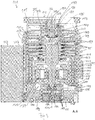
- einen Querschnitt der Turbomolekularpumpe längs der in
Fig. 2 gezeigten Schnittlinie A-A, - Fig. 4
- eine Querschnittsansicht der Turbomolekularpumpe längs der in
Fig. 2 gezeigten Schnittlinie B-B, - Fig. 5
- eine Querschnittsansicht der Turbomolekularpumpe längs der in
Fig. 2 gezeigten Schnittlinie C-C, - Fig. 6
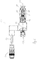
- eine Querschnittsansicht eines aus dem Stand der Technik bekannten Einlassventils,
- Fig. 7
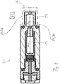
- eine Querschnittsansicht einer vorteilhaften Variante eines erfindungsgemäßen Einlassventils, und
- Fig. 8
- eine Querschnittsansicht einer weiteren vorteilhaften Variante eines erfindungsgemäßen Einlassventils.
- Die in
Fig. 1 gezeigte Turbomolekularpumpe 111 umfasst einen von einem Einlassflansch 113 umgebenen Pumpeneinlass 115, an welchen in an sich bekannter Weise ein nicht dargestellter Rezipient angeschlossen werden kann. Das Gas aus dem Rezipienten kann über den Pumpeneinlass 115 aus dem Rezipienten gesaugt und durch die Pumpe hindurch zu einem Pumpenauslass 117 gefördert werden, an den eine Vorvakuumpumpe, wie etwa eine Drehschieberpumpe, angeschlossen sein kann. - Der Einlassflansch 113 bildet bei der Ausrichtung der Vakuumpumpe gemäß
Fig. 1 das obere Ende des Gehäuses 119 der Vakuumpumpe 111. Das Gehäuse 119 umfasst ein Unterteil 121, an welchem seitlich ein Elektronikgehäuse 123 angeordnet ist. In dem Elektronikgehäuse 123 sind elektrische und/oder elektronische Komponenten der Vakuumpumpe 111 untergebracht, z.B. zum Betreiben eines in der Vakuumpumpe angeordneten Elektromotors 125. Am Elektronikgehäuse 123 sind mehrere Anschlüsse 127 für Zubehör vorgesehen. Außerdem sind eine Datenschnittstelle 129, z.B. gemäß dem RS485-Standard, und ein Stromversorgungsanschluss 131 am Elektronikgehäuse 123 angeordnet. - Am Gehäuse 119 der Turbomolekularpumpe 111 ist ein Fluteinlass 133, insbesondere in Form eines Flutventils, vorgesehen, über den die Vakuumpumpe 111 geflutet werden kann. Im Bereich des Unterteils 121 ist ferner noch ein Sperrgasanschluss 135, der auch als Spülgasanschluss bezeichnet wird, angeordnet, über welchen Spülgas zum Schutz des Elektromotors 125 vor dem von der Pumpe geförderten Gas in den Motorraum 137, in welchem der Elektromotor 125 in der Vakuumpumpe 111 untergebracht ist, gebracht werden kann. Im Unterteil 121 sind ferner noch zwei Kühlmittelanschlüsse 139 angeordnet, wobei einer der Kühlmittelanschlüsse als Einlass und der andere Kühlmittelanschluss als Auslass für Kühlmittel vorgesehen ist, das zu Kühlzwecken in die Vakuumpumpe geleitet werden kann.
- Die untere Seite 141 der Vakuumpumpe kann als Standfläche dienen, sodass die Vakuumpumpe 111 auf der Unterseite 141 stehend betrieben werden kann. Die Vakuumpumpe 111 kann aber auch über den Einlassflansch 113 an einem Rezipienten befestigt werden und somit gewissermaßen hängend betrieben werden. Außerdem kann die Vakuumpumpe 111 so gestaltet sein, dass sie auch in Betrieb genommen werden kann, wenn sie auf andere Weise ausgerichtet ist als in
Fig. 1 gezeigt ist. Es lassen sich auch Ausführungsformen der Vakuumpumpe realisieren, bei der die Unterseite 141 nicht nach unten, sondern zur Seite gewandt oder nach oben gerichtet angeordnet werden kann. - An der Unterseite 141, die in
Fig. 2 dargestellt ist, sind noch diverse Schrauben 143 angeordnet, mittels denen hier nicht weiter spezifizierte Bauteile der Vakuumpumpe aneinander befestigt sind. Beispielsweise ist ein Lagerdeckel 145 an der Unterseite 141 befestigt. - An der Unterseite 141 sind außerdem Befestigungsbohrungen 147 angeordnet, über welche die Pumpe 111 beispielsweise an einer Auflagefläche befestigt werden kann.
- In den
Figuren 2 bis 5 ist eine Kühlmittelleitung 148 dargestellt, in welcher das über die Kühlmittelanschlüsse 139 ein- und ausgeleitete Kühlmittel zirkulieren kann. - Wie die Schnittdarstellungen der
Figuren 3 bis 5 zeigen, umfasst die Vakuumpumpe mehrere Prozessgaspumpstufen zur Förderung des an dem Pumpeneinlass 115 anstehenden Prozessgases zu dem Pumpenauslass 117. - In dem Gehäuse 119 ist ein Rotor 149 angeordnet, der eine um eine Rotationsachse 151 drehbare Rotorwelle 153 aufweist.
- Die Turbomolekularpumpe 111 umfasst mehrere pumpwirksam miteinander in Serie geschaltete turbomolekulare Pumpstufen mit mehreren an der Rotorwelle 153 befestigten radialen Rotorscheiben 155 und zwischen den Rotorscheiben 155 angeordneten und in dem Gehäuse 119 festgelegten Statorscheiben 157. Dabei bilden eine Rotorscheibe 155 und eine benachbarte Statorscheibe 157 jeweils eine turbomolekulare Pumpstufe. Die Statorscheiben 157 sind durch Abstandsringe 159 in einem gewünschten axialen Abstand zueinander gehalten.
- Die Vakuumpumpe umfasst außerdem in radialer Richtung ineinander angeordnete und pumpwirksam miteinander in Serie geschaltete Holweck-Pumpstufen. Der Rotor der Holweck-Pumpstufen umfasst eine an der Rotorwelle 153 angeordnete Rotornabe 161 und zwei an der Rotornabe 161 befestigte und von dieser getragene zylindermantelförmige Holweck-Rotorhülsen 163, 165, die koaxial zur Rotationsachse 151 orientiert und in radialer Richtung ineinander geschachtelt sind. Ferner sind zwei zylindermantelförmige Holweck-Statorhülsen 167, 169 vorgesehen, die ebenfalls koaxial zu der Rotationsachse 151 orientiert und in radialer Richtung gesehen ineinander geschachtelt sind.
- Die pumpaktiven Oberflächen der Holweck-Pumpstufen sind durch die Mantelflächen, also durch die radialen Innen- und/oder Außenflächen, der Holweck-Rotorhülsen 163, 165 und der Holweck-Statorhülsen 167, 169 gebildet. Die radiale Innenfläche der äußeren Holweck-Statorhülse 167 liegt der radialen Außenfläche der äußeren Holweck-Rotorhülse 163 unter Ausbildung eines radialen Holweck-Spalts 171 gegenüber und bildet mit dieser die der Turbomolekularpumpen nachfolgende erste Holweck-Pumpstufe. Die radiale Innenfläche der äußeren Holweck-Rotorhülse 163 steht der radialen Außenfläche der inneren Holweck-Statorhülse 169 unter Ausbildung eines radialen Holweck-Spalts 173 gegenüber und bildet mit dieser eine zweite Holweck-Pumpstufe. Die radiale Innenfläche der inneren Holweck-Statorhülse 169 liegt der radialen Außenfläche der inneren Holweck-Rotorhülse 165 unter Ausbildung eines radialen Holweck-Spalts 175 gegenüber und bildet mit dieser die dritte Holweck-Pumpstufe.
- Am unteren Ende der Holweck-Rotorhülse 163 kann ein radial verlaufender Kanal vorgesehen sein, über den der radial außenliegende Holweck-Spalt 171 mit dem mittleren Holweck-Spalt 173 verbunden ist. Außerdem kann am oberen Ende der inneren Holweck-Statorhülse 169 ein radial verlaufender Kanal vorgesehen sein, über den der mittlere Holweck-Spalt 173 mit dem radial innenliegenden Holweck-Spalt 175 verbunden ist. Dadurch werden die ineinander geschachtelten Holweck-Pumpstufen in Serie miteinander geschaltet. Am unteren Ende der radial innenliegenden Holweck-Rotorhülse 165 kann ferner ein Verbindungskanal 179 zum Auslass 117 vorgesehen sein.
- Die vorstehend genannten pumpaktiven Oberflächen der Holweck-Statorhülsen 163, 165 weisen jeweils mehrere spiralförmig um die Rotationsachse 151 herum in axialer Richtung verlaufende Holweck-Nuten auf, während die gegenüberliegenden Mantelflächen der Holweck-Rotorhülsen 163, 165 glatt ausgebildet sind und das Gas zum Betrieb der Vakuumpumpe 111 in den Holweck-Nuten vorantreiben.
- Zur drehbaren Lagerung der Rotorwelle 153 sind ein Wälzlager 181 im Bereich des Pumpenauslasses 117 und ein Permanentmagnetlager 183 im Bereich des Pumpeneinlasses 115 vorgesehen.
- Im Bereich des Wälzlagers 181 ist an der Rotorwelle 153 eine konische Spritzmutter 185 mit einem zu dem Wälzlager 181 hin zunehmenden Außendurchmesser vorgesehen. Die Spritzmutter 185 steht mit mindestens einem Abstreifer eines Betriebsmittelspeichers in gleitendem Kontakt. Der Betriebsmittelspeicher umfasst mehrere aufeinander gestapelte saugfähige Scheiben 187, die mit einem Betriebsmittel für das Wälzlager 181, z.B. mit einem Schmiermittel, getränkt sind.
- Im Betrieb der Vakuumpumpe 111 wird das Betriebsmittel durch kapillare Wirkung von dem Betriebsmittelspeicher über den Abstreifer auf die rotierende Spritzmutter 185 übertragen und in Folge der Zentrifugalkraft entlang der Spritzmutter 185 in Richtung des größer werdenden Außendurchmessers der Spritzmutter 92 zu dem Wälzlager 181 hin gefördert, wo es z.B. eine schmierende Funktion erfüllt. Das Wälzlager 181 und der Betriebsmittelspeicher sind durch einen wannenförmigen Einsatz 189 und den Lagerdeckel 145 in der Vakuumpumpe eingefasst.
- Das Permanentmagnetlager 183 umfasst eine rotorseitige Lagerhälfte 191 und eine statorseitige Lagerhälfte 193, welche jeweils einen Ringstapel aus mehreren in axialer Richtung aufeinander gestapelten permanentmagnetischen Ringen 195, 197 umfassen. Die Ringmagnete 195, 197 liegen einander unter Ausbildung eines radialen Lagerspalts 199 gegenüber, wobei die rotorseitigen Ringmagnete 195 radial außen und die statorseitigen Ringmagnete 197 radial innen angeordnet sind. Das in dem Lagerspalt 199 vorhandene magnetische Feld ruft magnetische Abstoßungskräfte zwischen den Ringmagneten 195, 197 hervor, welche eine radiale Lagerung der Rotorwelle 153 bewirken. Die rotorseitigen Ringmagnete 195 sind von einem Trägerabschnitt 201 der Rotorwelle 153 getragen, welcher die Ringmagnete 195 radial außenseitig umgibt. Die statorseitigen Ringmagnete 197 sind von einem statorseitigen Trägerabschnitt 203 getragen, welcher sich durch die Ringmagnete 197 hindurch erstreckt und an radialen Streben 205 des Gehäuses 119 aufgehängt ist. Parallel zu der Rotationsachse 151 sind die rotorseitigen Ringmagnete 195 durch ein mit dem Trägerabschnitt 203 gekoppeltes Deckelelement 207 festgelegt. Die statorseitigen Ringmagnete 197 sind parallel zu der Rotationsachse 151 in der einen Richtung durch einen mit dem Trägerabschnitt 203 verbundenen Befestigungsring 209 sowie einen mit dem Trägerabschnitt 203 verbundenen Befestigungsring 211 festgelegt. Zwischen dem Befestigungsring 211 und den Ringmagneten 197 kann außerdem eine Tellerfeder 213 vorgesehen sein.
- Innerhalb des Magnetlagers ist ein Not- bzw. Fanglager 215 vorgesehen, welches im normalen Betrieb der Vakuumpumpe 111 ohne Berührung leer läuft und erst bei einer übermäßigen radialen Auslenkung des Rotors 149 relativ zu dem Stator in Eingriff gelangt, um einen radialen Anschlag für den Rotor 149 zu bilden, da eine Kollision der rotorseitigen Strukturen mit den statorseitigen Strukturen verhindert wird. Das Fanglager 215 ist als ungeschmiertes Wälzlager ausgebildet und bildet mit dem Rotor 149 und/oder dem Stator einen radialen Spalt, welcher bewirkt, dass das Fanglager 215 im normalen Pumpbetrieb außer Eingriff ist. Die radiale Auslenkung, bei der das Fanglager 215 in Eingriff gelangt, ist groß genug bemessen, sodass das Fanglager 215 im normalen Betrieb der Vakuumpumpe nicht in Eingriff gelangt, und gleichzeitig klein genug, sodass eine Kollision der rotorseitigen Strukturen mit den statorseitigen Strukturen unter allen Umständen verhindert wird.
- Die Vakuumpumpe 111 umfasst den Elektromotor 125 zum drehenden Antreiben des Rotors 149. Der Anker des Elektromotors 125 ist durch den Rotor 149 gebildet, dessen Rotorwelle 153 sich durch den Motorstator 217 hindurch erstreckt. Auf den sich durch den Motorstator 217 hindurch erstreckenden Abschnitt der Rotorwelle 153 kann radial außenseitig oder eingebettet eine Permanentmagnetanordnung angeordnet sein. Zwischen dem Motorstator 217 und dem sich durch den Motorstator 217 hindurch erstreckenden Abschnitt des Rotors 149 ist ein Zwischenraum 219 angeordnet, welcher einen radialen Motorspalt umfasst, über den sich der Motorstator 217 und die Permanentmagnetanordnung zur Übertragung des Antriebsmoments magnetisch beeinflussen können.
- Der Motorstator 217 ist in dem Gehäuse innerhalb des für den Elektromotor 125 vorgesehenen Motorraums 137 festgelegt. Über den Sperrgasanschluss 135 kann ein Sperrgas, das auch als Spülgas bezeichnet wird, und bei dem es sich beispielsweise um Luft oder um Stickstoff handeln kann, in den Motorraum 137 gelangen. Über das Sperrgas kann der Elektromotor 125 vor Prozessgas, z.B. vor korrosiv wirkenden Anteilen des Prozessgases, geschützt werden. Der Motorraum 137 kann auch über den Pumpenauslass 117 evakuiert werden, d.h. im Motorraum 137 herrscht zumindest annäherungsweise der von der am Pumpenauslass 117 angeschlossenen Vorvakuumpumpe bewirkte Vakuumdruck.
- Zwischen der Rotornabe 161 und einer den Motorraum 137 begrenzenden Wandung 221 kann außerdem eine sog. und an sich bekannte Labyrinthdichtung 223 vorgesehen sein, insbesondere um eine bessere Abdichtung des Motorraums 217 gegenüber den radial außerhalb liegenden Holweck-Pumpstufen zu erreichen.
- Das in
Fig. 6 gezeigte Einlassventil 11 weist einen Kanal 13 auf, der sich zwischen einem Kanaleingang 15 und einem Kanalausgang 17 erstreckt. Der Kanalausgang 17 kann, wenn die inFig. 1 gezeigte Schraube abgenommen wird, in den Sperrgasanschluss 135 eingesteckt werden, um Sperrgas in den Motorraum 137 zu leiten, das wiederum über den Pumpenauslass 117 von einer daran angeschlossenen Vorvakuumpumpe abgepumpt werden kann. Genauer kann der Kanalausgang 17 mittels eines an seiner Außenseite ausgebildeten Gewindes 27 in den Sperrgasanschluss 135 eingeschraubt werden. Durch das Sperrgas kann der Motor 125 vor Prozessgas geschützt werden. Bei dem Sperrgas kann es sich um Stickstoff handeln. Dazu kann zum Beispiel ein Stickstoffreservoir an den Kanaleingang 15 angeschlossen werden. Der Kanaleingang 15 kann auch offen gelassen werden, so dass Luft aus der Atmosphäre als Sperrgas in die Vakuumpumpe gelangen kann. - Das Einlassventil 11 weist einen elektrischen Anschluss 19 auf, an den ein elektrischer Stecker 21 angeschlossen werden kann, um ein elektrisches Ventil 23, z. B. ein Magnetventil, im Einlassventil 11 zu betätigen. Durch das Ventil 21 kann der Kanal 13 geöffnet und geschlossen werden.
- Im Kanal 13 ist ferner noch ein Poralfilter 25 angeordnet. Außerdem ist ein Abschnitt des Kanals 13 in Form einer Kapillare 29, insbesondere Glaskapillare, ausgebildet. Durch die Kapillare 29 wird die Gasströmung des durch den Eingang 15 einströmenden Gases reduziert.
- Problematisch bei einem derartigen Einlassventil 11 ist, dass nicht erkannt werden kann, ob tatsächlich eine Gasströmung im Kanal 13 vom Einlass 15 zum Ausgang 17, also längs der Strömungsrichtung S, vorliegt. Es kann somit nicht erfasst werden, ob bei geöffnetem Ventil 23 tatsächlich Schutzgas in die Pumpe eingeleitet wird oder ob die Strömung unterbrochen ist. Beispielsweise kann der Kanal 13 durch Staub oder Schmutz verstopft sein, so dass keine Strömung mehr durch den Kanal 13 möglich ist.
- Bei dem Einlassventil 31 der
Fig. 7 weist der Kanal 13 an einer ersten Stelle 33 einen ersten Drucksensor 35 und an einer zweiten Stelle 37, die von der ersten Stelle 33 beabstandet ist, einen zweiten Drucksensor 39 auf. Somit kann der Druck des Gases an der ersten Stelle 33 und an der zweiten Stelle 37 gemessen werden. Die Drucksensoren 35, 39 gehören zu einer Messeinrichtung 41, bei der es sich um einen Pumpencontroller oder dergleichen handeln kann. Die Messeinrichtung 41 ist dazu ausgebildet, bei geöffnetem Ventil 23 (vgl.Fig. 6 ) in Abhängigkeit von dem ersten Druck, der mit dem ersten Drucksensor 35 gemessen wird, und dem zweiten Druck, der mit dem zweiten Drucksensor 39 gemessen wird, zu bestimmen, ob Gas längs des Kanals 15 strömt. - Die Messeinrichtung 41 kann beispielsweise den ersten Druck mit dem zweiten Druck vergleichen und annehmen, dass das Gas längs des Kanals strömt, wenn der erste Druck sich vom zweiten Druck unterscheidet. Wenn der erste Druck gleich dem zweiten Druck ist, kann die Messeinrichtung 41 dagegen annehmen, dass keine Gasströmung vorhanden ist und beispielsweise eine Fehlermeldung ausgeben. Da, wie nachfolgend erläutert wird, bei einer Gasströmung der erste Druck an der ersten Stelle 33 größer ist als der zweite Druck an der zweiten Stelle 37, kann die Messeinrichtung 41 ferner einen Fehler ausgeben, wenn sie feststellt, dass der zweite Druck größer als der erste Druck ist.
- Wie die
Fig. 7 zeigt, weist der Kanal 13 im Bereich der ersten Stelle 33 und im Bereich der zweiten Stelle 37 einen vergrößerten Querschnitt auf, da sich die erste Stelle 33 in einer ersten Kammer 43 und die zweite Stelle 37 in einer zweiten Kammer 45 befindet. Zwischen der ersten Kammer 43 und der zweiten Kammer 45 bildet der Kanal 13 eine Engstelle 47 in Art einer Kapillare. Das Gas, welches in Strömungsrichtung S durch den Kanal 13 strömt, wird somit beim Übergang von der ersten Kammer 43 in die Engstelle 47 verblockt, was dazu führt, dass bei einer vorhandenen Gasströmung der Druck an der ersten Stelle 33 höher ist als der Druck an der zweiten Stelle 37. Durch eine Messung des ersten und des zweiten Drucks an der ersten bzw. zweiten Stelle 33, 37 kann somit, wie beschrieben, von der Messeinrichtung 41 festgestellt werden, ob bei geöffnetem Ventil tatsächlich eine Gasströmung durch den Kanal 13 vorliegt. - Im Unterschied zu dem Einlassventil 31 der
Fig. 7 sind bei dem Einlassventil 51 derFig. 8 die erste Stelle 33 mit dem ersten Drucksensor 35 und die zweite Stelle 37 mit dem zweiten Drucksensor 39 in einer in Strömungsrichtung S gesehen der Kapillare 29 nachgeordneten Kammer 53 angeordnet. Die zweite Stelle 39 befindet sich dabei an der Kammerwand, durch welche der in Strömungsrichtung S gesehen vorgeordnete Kanalabschnitt in die Kammer 53 mündet. Der zweite Sensor 39 befindet sich somit im Schatten der in die Kammer 53 einströmenden Gasströmung, während der erste Drucksensor 35 der Gasströmung ausgesetzt ist. Wenn somit eine Gasströmung vorliegt, misst der erste Drucksensor 35 einen ersten Druck, der höher ist als der vom zweiten Drucksensor 39 gemessene zweite Druck. Wie vorstehend mit Bezug aufFig. 7 beschrieben wurde, kann somit die Messeinrichtung 41 in Abhängigkeit der gemessenen Drücke bestimmen, ob tatsächlich eine Gasströmung vorliegt. - Ein Einlassventil 31, 51 kann auch an den Fluteinlass 133 der Pumpe 111 angeschlossen werden, um während des Belüftens der Pumpe 111 überwachen zu können, dass tatsächlich Luft in die Pumpe 111 einströmt. Ein entsprechendes Einlassventil kann auch an einem anderen Einlass einer Pumpe vorgesehen sein.
-
- 11
- Einlassventil
- 13
- Kanal
- 15
- Kanaleingang
- 17
- Kanalausgang
- 19
- elektrischer Anschluss
- 21
- Stecker
- 23
- Ventil
- 25
- Poralfilter
- 27
- Gewinde
- 29
- Kapillare
- 31
- Einlassventil
- 33
- erste Stelle
- 35
- erster Drucksensor
- 37
- zweite Stelle
- 39
- zweiter Drucksensor
- 41
- Messeinrichtung
- 43
- erste Kammer
- 45
- zweite Kammer
- 47
- Engstelle
- 51
- Einlassventil
- 53
- Kammer
- 111
- Turbomolekularpumpe
- 113
- Einlassflansch
- 115
- Pumpeneinlass
- 117
- Pumpenauslass
- 119
- Gehäuse
- 121
- Unterteil
- 123
- Elektronikgehäuse
- 125
- Elektromotor
- 127
- Zubehöranschluss
- 129
- Datenschnittstelle
- 131
- Stromversorgungsanschluss
- 133
- Fluteinlass
- 135
- Sperrgasanschluss
- 137
- Motorraum
- 139
- Kühlmittelanschluss
- 141
- Unterseite
- 143
- Schraube
- 145
- Lagerdeckel
- 147
- Befestigungsbohrung
- 148
- Kühlmittelleitung
- 149
- Rotor
- 151
- Rotationsachse
- 153
- Rotorwelle
- 155
- Rotorscheibe
- 157
- Statorscheibe
- 159
- Abstandsring
- 161
- Rotornabe
- 163
- Holweck-Rotorhülse
- 165
- Holweck-Rotorhülse
- 167
- Holweck-Statorhülse
- 169
- Holweck-Statorhülse
- 171
- Holweck-Spalt
- 173
- Holweck-Spalt
- 175
- Holweck-Spalt
- 179
- Verbindungskanal
- 181
- Wälzlager
- 183
- Permanentmagnetlager
- 185
- Spritzmutter
- 187
- Scheibe
- 189
- Einsatz
- 191
- rotorseitige Lagerhälfte
- 193
- statorseitige Lagerhälfte
- 195
- Ringmagnet
- 197
- Ringmagnet
- 199
- Lagerspalt
- 201
- Trägerabschnitt
- 203
- Trägerabschnitt
- 205
- radiale Strebe
- 207
- Deckelelement
- 209
- Stützring
- 211
- Befestigungsring
- 213
- Tellerfeder
- 215
- Not-bzw. Fanglager
- 217
- Motorstator
- 219
- Zwischenraum
- 221
- Wandung
- 223
- Labyrinthdichtung
- S
- Strömungsrichtung
- 183
- Permanentmagnetlager
- 185
- Spritzmutter
- 187
- Scheibe
- 189
- Einsatz
- 191
- rotorseitige Lagerhälfte
- 193
- statorseitige Lagerhälfte
- 195
- Ringmagnet
- 197
- Ringmagnet
- 199
- Lagerspalt
- 201
- Trägerabschnitt
- 203
- Trägerabschnitt
- 205
- radiale Strebe
- 207
- Deckelelement
- 209
- Stützring
- 211
- Befestigungsring
- 213
- Tellerfeder
- 215
- Not- bzw. Fanglager
- 217
- Motorstator
- 219
- Zwischenraum
- 221
- Wandung
- 223
- Labyrinthdichtung
- S
- Strömungsrichtung
Claims (13)
- Vakuumpumpe, insbesondere Turbomolekularpumpe, zum Fördern eines Prozessgases von einem ersten Einlass (115) der Vakuumpumpe (111) durch wenigstens eine Pumpstufe, insbesondere eine turbomolekulare und/oder molekulare Pumpstufe, hindurch zu einem Auslass (117) der Vakuumpumpe (111),
mit einem Einlassventil (31, 51), das an einem zweiten Einlass (133, 135) der Vakuumpumpe angeschlossen ist,
wobei das Einlassventil einen Kanal (13) aufweist, durch welchen ein von dem Prozessgas verschiedenes Gas in die Pumpe geleitet werden kann,
wobei eine Messeinrichtung (41) vorgesehen ist, die dazu ausgebildet ist, wenigstens an einer ersten Stelle (33) im Kanal (13) einen ersten Druck und an einer zur ersten Stelle (33) beabstandeten zweiten Stelle (37) im Kanal (13) einen zweiten Druck des im Kanal (13) befindlichen Gases zu messen und in Abhängigkeit von dem ersten Druck und dem zweiten Druck zu bestimmen, ob das Gas längs des Kanals (13) strömt. - Vakuumpumpe nach Anspruch 1,
dadurch gekennzeichnet, dass
die Messeinrichtung (41) dazu ausgebildet ist, anzunehmen, dass das Gas längs des Kanals (13) strömt, wenn der erste Druck sich vom zweiten Druck unterscheidet. - Vakuumpumpe nach Anspruch 1 oder 2,
dadurch gekennzeichnet, dass
die Messeinrichtung (41) dazu ausgebildet ist, anzunehmen, dass keine Gasströmung im Kanal (13) vorhanden ist, wenn der erste Druck gleich dem zweiten Druck ist. - Vakuumpumpe nach Anspruch 3,
dadurch gekennzeichnet, dass
die Messeinrichtung (41) dazu ausgebildet ist, einen Fehler anzuzeigen, wenn angenommen wird, dass keine Gasströmung im Kanal (13) vorhanden ist. - Vakuumpumpe nach einem der vorhergehenden Ansprüche,
dadurch gekennzeichnet, dass
der Kanal (13) an der ersten Stelle (33) und/oder an der zweiten Stelle (37) einen vergrößerten Querschnitt aufweist, insbesondere derart, dass der Kanal (13) im Bereich der ersten Stelle (33) eine erste Kammer (43) und/oder im Bereich der zweiten Stelle (37) eine zweite Kammer (45) ausbildet. - Vakuumpumpe nach einem der vorhergehenden Ansprüche,
dadurch gekennzeichnet, dass
ein zwischen der ersten Stelle (33) und der zweiten Stelle (37) liegender Abschnitt des Kanals (47) einen kleineren Querschnitt aufweist als der Kanal (13) an der ersten Stelle (33) oder der zweiten Stelle (37). - Vakuumpumpe nach Anspruch 6,
dadurch gekennzeichnet, dass
der Kanalabschnitt (47) eine Engstelle, insbesondere in Art einer Kapillare, aufweist. - Vakuumpumpe nach einem der Ansprüche 1 bis 4,
dadurch gekennzeichnet, dass
der Kanal (13) eine Kammer (53) aufweist, in welcher sowohl die erste Stelle (33) als auch die zweite Stelle (37) vorgesehen ist. - Vakuumpumpe nach einem der vorhergehenden Ansprüche,
dadurch gekennzeichnet, dass
eine von der ersten Stelle (33) oder der zweiten Stelle (37) in einer Kammer (53) vorgesehen ist, sich an einer Wand der Kammer (53) befindet, durch welche ein in Strömungsrichtung (S) gesehen vorgeordneter Kanalabschnitt in die Kammer (53) mündet, und somit im Schatten der Gasströmung angeordnet ist, während die andere der ersten Stelle (33) oder der zweiten Stelle (37) der Gasströmung ausgesetzt ist. - Vakuumpumpe nach einem der vorhergehenden Ansprüche,
dadurch gekennzeichnet, dass
der Kanal (13) stromaufwärts der ersten Stelle (33) und der zweiten Stelle (37) wenigstens eine Engstelle (29), insbesondere in Art einer Kapillare, aufweist. - Vakuumpumpe nach einem der vorhergehenden Ansprüche, dadurch gekennzeichnet, dass
es sich bei dem Kanal (13) um einen Kanal zum Einbringen von Sperrgas in den Motorraum (137) der Vakuumpumpe (111) oder um einen Flutkanal zum Fluten der Vakuumpumpe (111) oder um einen Kanal zum Einbringen von Schleppgas in die Vakuumpumpe (111) handelt. - Verfahren zum Überwachen einer Strömung eines Gases längs eines Kanals (13) eines Einlassventils (31, 51), welches an einem zweiten Einlass einer Vakuumpumpe gemäß einem der vorhergehenden Ansprüche angeschlossen ist, und durch welchen Kanal das Gas in die Pumpe (111) geleitet werden kann, wobei wenigstens an einer ersten Stelle (33) im Kanal (13) ein erster Druck und an einer zur ersten Stelle (33) beabstandeten zweiten Stelle (37) im Kanal (13) ein zweiter Druck des im Kanal (13) befindlichen Gases gemessen und in Abhängigkeit von dem ersten Druck und dem zweiten Druck bestimmt wird, ob das Gas längs des Kanals (13) strömt.
- Verfahren nach Anspruch 12, dadurch gekennzeichnet, dass
in Abhängigkeit von der Differenz zwischen dem ersten Druck und dem zweiten Druck bestimmt wird, ob das Gas längs des Kanals (13) strömt.
Priority Applications (1)
| Application Number | Priority Date | Filing Date | Title |
|---|---|---|---|
| EP15174408.3A EP3112687B1 (de) | 2015-06-29 | 2015-06-29 | Feststellung der strömung eines hilfsgases, das in eine vakuumpumpe gespeist wird |
Applications Claiming Priority (1)
| Application Number | Priority Date | Filing Date | Title |
|---|---|---|---|
| EP15174408.3A EP3112687B1 (de) | 2015-06-29 | 2015-06-29 | Feststellung der strömung eines hilfsgases, das in eine vakuumpumpe gespeist wird |
Publications (2)
| Publication Number | Publication Date |
|---|---|
| EP3112687A1 EP3112687A1 (de) | 2017-01-04 |
| EP3112687B1 true EP3112687B1 (de) | 2020-04-22 |
Family
ID=53496529
Family Applications (1)
| Application Number | Title | Priority Date | Filing Date |
|---|---|---|---|
| EP15174408.3A Active EP3112687B1 (de) | 2015-06-29 | 2015-06-29 | Feststellung der strömung eines hilfsgases, das in eine vakuumpumpe gespeist wird |
Country Status (1)
| Country | Link |
|---|---|
| EP (1) | EP3112687B1 (de) |
Families Citing this family (4)
| Publication number | Priority date | Publication date | Assignee | Title |
|---|---|---|---|---|
| EP3431769B1 (de) * | 2017-07-21 | 2022-05-04 | Pfeiffer Vacuum Gmbh | Vakuumpumpe |
| CN111622966B (zh) * | 2020-06-18 | 2025-02-14 | 天津飞旋科技股份有限公司 | 一种防水型一体化分子泵 |
| DE102020116770B4 (de) | 2020-06-25 | 2022-10-13 | Pfeiffer Vacuum Technology AG | Vakuumpumpe mit integriertem miniaturventil |
| FR3121962B1 (fr) * | 2021-04-16 | 2023-05-12 | Pfeiffer Vacuum | Pompe à vide |
Citations (1)
| Publication number | Priority date | Publication date | Assignee | Title |
|---|---|---|---|---|
| WO2001075374A1 (en) * | 2000-04-04 | 2001-10-11 | Federspiel Clifford C | Pressure based flow rate measurement device integrated with blades of a damper |
Family Cites Families (2)
| Publication number | Priority date | Publication date | Assignee | Title |
|---|---|---|---|---|
| FR2044016A5 (de) * | 1969-05-06 | 1971-02-19 | Sud Aviation | |
| GB0504553D0 (en) * | 2005-03-07 | 2005-04-13 | Boc Group Plc | Apparatus for inhibiting the propagation of a flame front |
-
2015
- 2015-06-29 EP EP15174408.3A patent/EP3112687B1/de active Active
Patent Citations (1)
| Publication number | Priority date | Publication date | Assignee | Title |
|---|---|---|---|---|
| WO2001075374A1 (en) * | 2000-04-04 | 2001-10-11 | Federspiel Clifford C | Pressure based flow rate measurement device integrated with blades of a damper |
Also Published As
| Publication number | Publication date |
|---|---|
| EP3112687A1 (de) | 2017-01-04 |
Similar Documents
| Publication | Publication Date | Title |
|---|---|---|
| EP2826999B1 (de) | Vakuumpumpe | |
| EP3657021B1 (de) | Vakuumpumpe | |
| EP3112687B1 (de) | Feststellung der strömung eines hilfsgases, das in eine vakuumpumpe gespeist wird | |
| EP3557073A1 (de) | Vakuumpumpe | |
| EP3653885B1 (de) | Verfahren zum ermitteln einer zustandsinformation in einem vakuumgerät | |
| EP1706645A1 (de) | Mehrstufige reibungsvakuumpumpe | |
| EP3438460B1 (de) | Vakuumpumpe | |
| EP3845764A2 (de) | Vakuumpumpe und vakuumpumpensystem | |
| EP3135932B1 (de) | Vakuumpumpe und permanentmagnetlager | |
| EP3318763B1 (de) | Vakuumdichtung, doppeldichtung, vakuumsystem und vakuumpumpe | |
| EP2910791A1 (de) | Vakuumpumpe | |
| EP3327293B1 (de) | Vakuumpumpe mit mehreren einlässen | |
| DE102014218937A1 (de) | Wellendichtung, Verfahren zum Betrieb | |
| EP3557072B1 (de) | Überwachung der lagereinrichtung einer vakuumpumpe | |
| EP2990656A2 (de) | Vakuumpumpe | |
| EP4194700B1 (de) | Vakuumpumpe mit einer holweck-pumpstufe mit veränderlicher holweck-geometrie | |
| EP0690204A2 (de) | Kondensationsturbine mit mindestens zwei Dichtungen zur Abdichtung des Turbinengehäuses | |
| DE102015113821B4 (de) | Vakuumpumpe | |
| DE102020116770B4 (de) | Vakuumpumpe mit integriertem miniaturventil | |
| EP3708843B1 (de) | Verfahren zur herstellung eines elektromotors oder eines vakuumgeräts mit einem solchen | |
| EP3339651B1 (de) | Vakuumpumpe | |
| EP3926174B1 (de) | Vakuumpumpe | |
| EP4137699B1 (de) | Vakuumgerät und verfahren zum betreiben eines solchen | |
| EP4293232B1 (de) | Turbomolekularpumpe | |
| EP2927501A1 (de) | Verfahren und System zur Ermittlung und Bewertung der Einbauorientierung einer Einrichtung |
Legal Events
| Date | Code | Title | Description |
|---|---|---|---|
| PUAI | Public reference made under article 153(3) epc to a published international application that has entered the european phase |
Free format text: ORIGINAL CODE: 0009012 |
|
| STAA | Information on the status of an ep patent application or granted ep patent |
Free format text: STATUS: THE APPLICATION HAS BEEN PUBLISHED |
|
| AK | Designated contracting states |
Kind code of ref document: A1 Designated state(s): AL AT BE BG CH CY CZ DE DK EE ES FI FR GB GR HR HU IE IS IT LI LT LU LV MC MK MT NL NO PL PT RO RS SE SI SK SM TR |
|
| AX | Request for extension of the european patent |
Extension state: BA ME |
|
| STAA | Information on the status of an ep patent application or granted ep patent |
Free format text: STATUS: REQUEST FOR EXAMINATION WAS MADE |
|
| 17P | Request for examination filed |
Effective date: 20170412 |
|
| RBV | Designated contracting states (corrected) |
Designated state(s): AL AT BE BG CH CY CZ DE DK EE ES FI FR GB GR HR HU IE IS IT LI LT LU LV MC MK MT NL NO PL PT RO RS SE SI SK SM TR |
|
| STAA | Information on the status of an ep patent application or granted ep patent |
Free format text: STATUS: EXAMINATION IS IN PROGRESS |
|
| 17Q | First examination report despatched |
Effective date: 20190705 |
|
| GRAP | Despatch of communication of intention to grant a patent |
Free format text: ORIGINAL CODE: EPIDOSNIGR1 |
|
| STAA | Information on the status of an ep patent application or granted ep patent |
Free format text: STATUS: GRANT OF PATENT IS INTENDED |
|
| GRAJ | Information related to disapproval of communication of intention to grant by the applicant or resumption of examination proceedings by the epo deleted |
Free format text: ORIGINAL CODE: EPIDOSDIGR1 |
|
| STAA | Information on the status of an ep patent application or granted ep patent |
Free format text: STATUS: EXAMINATION IS IN PROGRESS |
|
| INTG | Intention to grant announced |
Effective date: 20191125 |
|
| GRAP | Despatch of communication of intention to grant a patent |
Free format text: ORIGINAL CODE: EPIDOSNIGR1 |
|
| STAA | Information on the status of an ep patent application or granted ep patent |
Free format text: STATUS: GRANT OF PATENT IS INTENDED |
|
| INTC | Intention to grant announced (deleted) | ||
| INTG | Intention to grant announced |
Effective date: 20200107 |
|
| GRAS | Grant fee paid |
Free format text: ORIGINAL CODE: EPIDOSNIGR3 |
|
| GRAA | (expected) grant |
Free format text: ORIGINAL CODE: 0009210 |
|
| STAA | Information on the status of an ep patent application or granted ep patent |
Free format text: STATUS: THE PATENT HAS BEEN GRANTED |
|
| AK | Designated contracting states |
Kind code of ref document: B1 Designated state(s): AL AT BE BG CH CY CZ DE DK EE ES FI FR GB GR HR HU IE IS IT LI LT LU LV MC MK MT NL NO PL PT RO RS SE SI SK SM TR |
|
| REG | Reference to a national code |
Ref country code: CH Ref legal event code: EP |
|
| REG | Reference to a national code |
Ref country code: DE Ref legal event code: R096 Ref document number: 502015012334 Country of ref document: DE |
|
| REG | Reference to a national code |
Ref country code: IE Ref legal event code: FG4D Free format text: LANGUAGE OF EP DOCUMENT: GERMAN |
|
| REG | Reference to a national code |
Ref country code: AT Ref legal event code: REF Ref document number: 1260469 Country of ref document: AT Kind code of ref document: T Effective date: 20200515 |
|
| REG | Reference to a national code |
Ref country code: LT Ref legal event code: MG4D |
|
| REG | Reference to a national code |
Ref country code: NL Ref legal event code: MP Effective date: 20200422 |
|
| PG25 | Lapsed in a contracting state [announced via postgrant information from national office to epo] |
Ref country code: FI Free format text: LAPSE BECAUSE OF FAILURE TO SUBMIT A TRANSLATION OF THE DESCRIPTION OR TO PAY THE FEE WITHIN THE PRESCRIBED TIME-LIMIT Effective date: 20200422 Ref country code: GR Free format text: LAPSE BECAUSE OF FAILURE TO SUBMIT A TRANSLATION OF THE DESCRIPTION OR TO PAY THE FEE WITHIN THE PRESCRIBED TIME-LIMIT Effective date: 20200723 Ref country code: SE Free format text: LAPSE BECAUSE OF FAILURE TO SUBMIT A TRANSLATION OF THE DESCRIPTION OR TO PAY THE FEE WITHIN THE PRESCRIBED TIME-LIMIT Effective date: 20200422 Ref country code: IS Free format text: LAPSE BECAUSE OF FAILURE TO SUBMIT A TRANSLATION OF THE DESCRIPTION OR TO PAY THE FEE WITHIN THE PRESCRIBED TIME-LIMIT Effective date: 20200822 Ref country code: NO Free format text: LAPSE BECAUSE OF FAILURE TO SUBMIT A TRANSLATION OF THE DESCRIPTION OR TO PAY THE FEE WITHIN THE PRESCRIBED TIME-LIMIT Effective date: 20200722 Ref country code: LT Free format text: LAPSE BECAUSE OF FAILURE TO SUBMIT A TRANSLATION OF THE DESCRIPTION OR TO PAY THE FEE WITHIN THE PRESCRIBED TIME-LIMIT Effective date: 20200422 Ref country code: NL Free format text: LAPSE BECAUSE OF FAILURE TO SUBMIT A TRANSLATION OF THE DESCRIPTION OR TO PAY THE FEE WITHIN THE PRESCRIBED TIME-LIMIT Effective date: 20200422 Ref country code: PT Free format text: LAPSE BECAUSE OF FAILURE TO SUBMIT A TRANSLATION OF THE DESCRIPTION OR TO PAY THE FEE WITHIN THE PRESCRIBED TIME-LIMIT Effective date: 20200824 |
|
| PG25 | Lapsed in a contracting state [announced via postgrant information from national office to epo] |
Ref country code: BG Free format text: LAPSE BECAUSE OF FAILURE TO SUBMIT A TRANSLATION OF THE DESCRIPTION OR TO PAY THE FEE WITHIN THE PRESCRIBED TIME-LIMIT Effective date: 20200722 Ref country code: RS Free format text: LAPSE BECAUSE OF FAILURE TO SUBMIT A TRANSLATION OF THE DESCRIPTION OR TO PAY THE FEE WITHIN THE PRESCRIBED TIME-LIMIT Effective date: 20200422 Ref country code: HR Free format text: LAPSE BECAUSE OF FAILURE TO SUBMIT A TRANSLATION OF THE DESCRIPTION OR TO PAY THE FEE WITHIN THE PRESCRIBED TIME-LIMIT Effective date: 20200422 Ref country code: LV Free format text: LAPSE BECAUSE OF FAILURE TO SUBMIT A TRANSLATION OF THE DESCRIPTION OR TO PAY THE FEE WITHIN THE PRESCRIBED TIME-LIMIT Effective date: 20200422 |
|
| PG25 | Lapsed in a contracting state [announced via postgrant information from national office to epo] |
Ref country code: AL Free format text: LAPSE BECAUSE OF FAILURE TO SUBMIT A TRANSLATION OF THE DESCRIPTION OR TO PAY THE FEE WITHIN THE PRESCRIBED TIME-LIMIT Effective date: 20200422 |
|
| REG | Reference to a national code |
Ref country code: DE Ref legal event code: R097 Ref document number: 502015012334 Country of ref document: DE |
|
| PG25 | Lapsed in a contracting state [announced via postgrant information from national office to epo] |
Ref country code: MC Free format text: LAPSE BECAUSE OF FAILURE TO SUBMIT A TRANSLATION OF THE DESCRIPTION OR TO PAY THE FEE WITHIN THE PRESCRIBED TIME-LIMIT Effective date: 20200422 Ref country code: ES Free format text: LAPSE BECAUSE OF FAILURE TO SUBMIT A TRANSLATION OF THE DESCRIPTION OR TO PAY THE FEE WITHIN THE PRESCRIBED TIME-LIMIT Effective date: 20200422 Ref country code: DK Free format text: LAPSE BECAUSE OF FAILURE TO SUBMIT A TRANSLATION OF THE DESCRIPTION OR TO PAY THE FEE WITHIN THE PRESCRIBED TIME-LIMIT Effective date: 20200422 Ref country code: SM Free format text: LAPSE BECAUSE OF FAILURE TO SUBMIT A TRANSLATION OF THE DESCRIPTION OR TO PAY THE FEE WITHIN THE PRESCRIBED TIME-LIMIT Effective date: 20200422 Ref country code: EE Free format text: LAPSE BECAUSE OF FAILURE TO SUBMIT A TRANSLATION OF THE DESCRIPTION OR TO PAY THE FEE WITHIN THE PRESCRIBED TIME-LIMIT Effective date: 20200422 Ref country code: RO Free format text: LAPSE BECAUSE OF FAILURE TO SUBMIT A TRANSLATION OF THE DESCRIPTION OR TO PAY THE FEE WITHIN THE PRESCRIBED TIME-LIMIT Effective date: 20200422 |
|
| REG | Reference to a national code |
Ref country code: CH Ref legal event code: PL |
|
| PG25 | Lapsed in a contracting state [announced via postgrant information from national office to epo] |
Ref country code: PL Free format text: LAPSE BECAUSE OF FAILURE TO SUBMIT A TRANSLATION OF THE DESCRIPTION OR TO PAY THE FEE WITHIN THE PRESCRIBED TIME-LIMIT Effective date: 20200422 Ref country code: SK Free format text: LAPSE BECAUSE OF FAILURE TO SUBMIT A TRANSLATION OF THE DESCRIPTION OR TO PAY THE FEE WITHIN THE PRESCRIBED TIME-LIMIT Effective date: 20200422 |
|
| PLBE | No opposition filed within time limit |
Free format text: ORIGINAL CODE: 0009261 |
|
| STAA | Information on the status of an ep patent application or granted ep patent |
Free format text: STATUS: NO OPPOSITION FILED WITHIN TIME LIMIT |
|
| 26N | No opposition filed |
Effective date: 20210125 |
|
| PG25 | Lapsed in a contracting state [announced via postgrant information from national office to epo] |
Ref country code: LU Free format text: LAPSE BECAUSE OF NON-PAYMENT OF DUE FEES Effective date: 20200629 |
|
| REG | Reference to a national code |
Ref country code: BE Ref legal event code: MM Effective date: 20200630 |
|
| PG25 | Lapsed in a contracting state [announced via postgrant information from national office to epo] |
Ref country code: IE Free format text: LAPSE BECAUSE OF NON-PAYMENT OF DUE FEES Effective date: 20200629 Ref country code: CH Free format text: LAPSE BECAUSE OF NON-PAYMENT OF DUE FEES Effective date: 20200630 Ref country code: FR Free format text: LAPSE BECAUSE OF NON-PAYMENT OF DUE FEES Effective date: 20200630 Ref country code: LI Free format text: LAPSE BECAUSE OF NON-PAYMENT OF DUE FEES Effective date: 20200630 |
|
| PG25 | Lapsed in a contracting state [announced via postgrant information from national office to epo] |
Ref country code: BE Free format text: LAPSE BECAUSE OF NON-PAYMENT OF DUE FEES Effective date: 20200630 Ref country code: SI Free format text: LAPSE BECAUSE OF FAILURE TO SUBMIT A TRANSLATION OF THE DESCRIPTION OR TO PAY THE FEE WITHIN THE PRESCRIBED TIME-LIMIT Effective date: 20200422 |
|
| REG | Reference to a national code |
Ref country code: AT Ref legal event code: MM01 Ref document number: 1260469 Country of ref document: AT Kind code of ref document: T Effective date: 20200629 |
|
| PG25 | Lapsed in a contracting state [announced via postgrant information from national office to epo] |
Ref country code: AT Free format text: LAPSE BECAUSE OF NON-PAYMENT OF DUE FEES Effective date: 20200629 |
|
| PG25 | Lapsed in a contracting state [announced via postgrant information from national office to epo] |
Ref country code: TR Free format text: LAPSE BECAUSE OF FAILURE TO SUBMIT A TRANSLATION OF THE DESCRIPTION OR TO PAY THE FEE WITHIN THE PRESCRIBED TIME-LIMIT Effective date: 20200422 Ref country code: MT Free format text: LAPSE BECAUSE OF FAILURE TO SUBMIT A TRANSLATION OF THE DESCRIPTION OR TO PAY THE FEE WITHIN THE PRESCRIBED TIME-LIMIT Effective date: 20200422 Ref country code: CY Free format text: LAPSE BECAUSE OF FAILURE TO SUBMIT A TRANSLATION OF THE DESCRIPTION OR TO PAY THE FEE WITHIN THE PRESCRIBED TIME-LIMIT Effective date: 20200422 |
|
| PG25 | Lapsed in a contracting state [announced via postgrant information from national office to epo] |
Ref country code: MK Free format text: LAPSE BECAUSE OF FAILURE TO SUBMIT A TRANSLATION OF THE DESCRIPTION OR TO PAY THE FEE WITHIN THE PRESCRIBED TIME-LIMIT Effective date: 20200422 |
|
| PGFP | Annual fee paid to national office [announced via postgrant information from national office to epo] |
Ref country code: GB Payment date: 20250618 Year of fee payment: 11 |
|
| PGFP | Annual fee paid to national office [announced via postgrant information from national office to epo] |
Ref country code: CZ Payment date: 20250625 Year of fee payment: 11 |
|
| PGFP | Annual fee paid to national office [announced via postgrant information from national office to epo] |
Ref country code: DE Payment date: 20250827 Year of fee payment: 11 |
|
| PGFP | Annual fee paid to national office [announced via postgrant information from national office to epo] |
Ref country code: IT Payment date: 20250624 Year of fee payment: 11 |