EP3112701A1 - Schraubverbindung - Google Patents
Schraubverbindung Download PDFInfo
- Publication number
- EP3112701A1 EP3112701A1 EP15174955.3A EP15174955A EP3112701A1 EP 3112701 A1 EP3112701 A1 EP 3112701A1 EP 15174955 A EP15174955 A EP 15174955A EP 3112701 A1 EP3112701 A1 EP 3112701A1
- Authority
- EP
- European Patent Office
- Prior art keywords
- screw
- metal sheet
- hole
- structural element
- embossment
- Prior art date
- Legal status (The legal status is an assumption and is not a legal conclusion. Google has not performed a legal analysis and makes no representation as to the accuracy of the status listed.)
- Withdrawn
Links
- 239000002184 metal Substances 0.000 claims abstract description 71
- 238000004049 embossing Methods 0.000 claims description 5
- 238000010079 rubber tapping Methods 0.000 claims description 5
- 230000000284 resting effect Effects 0.000 claims description 3
- 230000000063 preceeding effect Effects 0.000 claims 1
- 238000007493 shaping process Methods 0.000 description 2
- 238000005406 washing Methods 0.000 description 2
- 238000005253 cladding Methods 0.000 description 1
- 230000007423 decrease Effects 0.000 description 1
- 230000001419 dependent effect Effects 0.000 description 1
- 238000011161 development Methods 0.000 description 1
- 230000018109 developmental process Effects 0.000 description 1
- 238000010586 diagram Methods 0.000 description 1
- 238000004519 manufacturing process Methods 0.000 description 1
- 239000000463 material Substances 0.000 description 1
- 238000012986 modification Methods 0.000 description 1
- 230000004048 modification Effects 0.000 description 1
- 230000002787 reinforcement Effects 0.000 description 1
- 230000007704 transition Effects 0.000 description 1
Images

Classifications
-
- F—MECHANICAL ENGINEERING; LIGHTING; HEATING; WEAPONS; BLASTING
- F16—ENGINEERING ELEMENTS AND UNITS; GENERAL MEASURES FOR PRODUCING AND MAINTAINING EFFECTIVE FUNCTIONING OF MACHINES OR INSTALLATIONS; THERMAL INSULATION IN GENERAL
- F16B—DEVICES FOR FASTENING OR SECURING CONSTRUCTIONAL ELEMENTS OR MACHINE PARTS TOGETHER, e.g. NAILS, BOLTS, CIRCLIPS, CLAMPS, CLIPS OR WEDGES; JOINTS OR JOINTING
- F16B25/00—Screws that cut thread in the body into which they are screwed, e.g. wood screws
- F16B25/001—Screws that cut thread in the body into which they are screwed, e.g. wood screws characterised by the material of the body into which the screw is screwed
- F16B25/0021—Screws that cut thread in the body into which they are screwed, e.g. wood screws characterised by the material of the body into which the screw is screwed the material being metal, e.g. sheet-metal or aluminium
-
- F—MECHANICAL ENGINEERING; LIGHTING; HEATING; WEAPONS; BLASTING
- F16—ENGINEERING ELEMENTS AND UNITS; GENERAL MEASURES FOR PRODUCING AND MAINTAINING EFFECTIVE FUNCTIONING OF MACHINES OR INSTALLATIONS; THERMAL INSULATION IN GENERAL
- F16B—DEVICES FOR FASTENING OR SECURING CONSTRUCTIONAL ELEMENTS OR MACHINE PARTS TOGETHER, e.g. NAILS, BOLTS, CIRCLIPS, CLAMPS, CLIPS OR WEDGES; JOINTS OR JOINTING
- F16B37/00—Nuts or like thread-engaging members
- F16B37/005—Nuts or like thread-engaging members into which threads are cut during screwing
-
- F—MECHANICAL ENGINEERING; LIGHTING; HEATING; WEAPONS; BLASTING
- F16—ENGINEERING ELEMENTS AND UNITS; GENERAL MEASURES FOR PRODUCING AND MAINTAINING EFFECTIVE FUNCTIONING OF MACHINES OR INSTALLATIONS; THERMAL INSULATION IN GENERAL
- F16B—DEVICES FOR FASTENING OR SECURING CONSTRUCTIONAL ELEMENTS OR MACHINE PARTS TOGETHER, e.g. NAILS, BOLTS, CIRCLIPS, CLAMPS, CLIPS OR WEDGES; JOINTS OR JOINTING
- F16B5/00—Joining sheets or plates, e.g. panels, to one another or to strips or bars parallel to them
- F16B5/02—Joining sheets or plates, e.g. panels, to one another or to strips or bars parallel to them by means of fastening members using screw-thread
- F16B5/0258—Joining sheets or plates, e.g. panels, to one another or to strips or bars parallel to them by means of fastening members using screw-thread using resiliently deformable sleeves, grommets or inserts
Definitions
- the present invention relates to the field of screw connections. More specifically, the present invention relates to a screw connection being adapted to provide a reliable connection between a thin metal sheet and a structural element.
- Household or kitchen appliances e.g. baking ovens, dish washers, washing machines etc. are known in prior art. Recent developments tend to reduce the thickness of metal sheets in order to save resources and reduce the weight of the household or kitchen appliances.
- the invention relates to a screw connection.
- the screw connection comprises a structural element including a screw hole.
- the structural element may be, for example, a frame element of any other element.
- the structural element may be constituted by a metal sheet.
- the screw connection may comprise a metal sheet to be fixed at said structural element.
- the metal sheet may comprise a through hole.
- the structural element and the metal sheet are adapted to be connected by means of a screw.
- Said screw may be screwed through the through hole of the metal sheet into the screw hole of the structural element. Thereby, the screw may pass the through hole without any engagement of the thread in the side wall limiting the through hole in radial direction.
- the metal sheet comprises an embossment. Said embossment at least partially surrounds the through hole in order to increase the distance between an upper surface of the metal sheet and the screw hole provided in the structural element in the area of the screw connection.
- the embossment is obtained by partial metal forming or deep drawing of the metal sheet.
- the embossment comprises a support portion, the support portion at least partially resting at the structural element and at least partially radially confining the through hole.
- the support portion can be constituted by a portion of the metal sheet that protrudes downwardly and that comprises a free end that is oriented to abut essentially perpendicularly on the structural element.
- the downwardly protruding support portion with the free end protrudes from the upper portion forming the contact surface for the screw head towards the structural element.
- the free end of the support portion that rests perpendicularly on the structural element provides asupport of the upper portion of the embossment with a high stiffness.
- the upper portion comprises a high structural strength when applying a fastening torque to the screw and a deformation of said upper portion is avoided.
- the support portion is formed by a ring-shaped rim.
- Said ring-shaped rim may confine the through-hole in radial direction.
- the ring-shaped rim may border a cavity provided in the embossment towards the through hole. Due to the ring-shaped rim, a uniform support of the upper portion of the embossment is obtained.
- the embossment comprises an upper portion comprising a contact surface, the screw head of the screw being adapted to rest against said contact surface. Due to said resting of the screw head on the contact surface, and the gap between the metal sheet and the structural element, a distancing of the screw head from the screw hole provided within the structural element is obtained.
- the support portion protrudes from the upper portion downwardly towards the structural element.
- the support portion is arranged in parallel to the longitudinal direction of the screw. Thereby, a reliable support of the upper portion in case of applying a fastening torque on the screw is obtained.
- the embossing comprises an annular, cup-like shape.
- the embossing may comprise an annular recess which is arranged around the through hole and which comprises an opening facing the structural element.
- Said annular recess may be confined in radial direction by the support portion and a connection portion.
- Said support portion may border the annular recess towards the through hole, whereas the connection portion provides a radial outer border of the annular recess.
- the connection portion may couple the embossment with the remaining portion of the metal sheet.
- the metal sheet comprises a wall thickness below 0.5mm.
- the wall thickness may be 0.2mm, 0.25mm, 0.3mm, 0.35mm, 0.4mm or 0.45 or any intermediate value between said wall thickness values.
- the structural element is at least partially formed by a metal sheet.
- the structural element may be a frame made of metal sheet material.
- the screw is a self-tapping screw.
- Self-tapping screws often comprise a thread which tails off in direct proximity of the screw head. So in case of using self-tapping screws, the usage of an embossment is preferred.
- the invention refers to a household or kitchen appliance comprising a screw connection according to anyone of the preceding embodiments.
- Fig. 1 illustrates an example embodiment of a screw connection 1.
- the screw connection 1 comprises a structural element 2 and a metal sheet 3.
- the structural element 2 may be, for example, a metal sheet, too.
- the structural element 2 is referred to as first metal sheet 2 and the metal sheet 3 is referred to as second metal sheet 3.
- Said first and second metal sheets 2, 3 may form part of complex components of kitchen or household appliances.
- the first metal sheet 2 may be, for example, a part of a household appliance, e.g. a metal cladding element, a frame element or a structural unit of a household appliance or the like.
- the second metal sheet 3 may be, for example, a housing element of the kitchen or household appliance or any other component, which has to be fixed to the first metal sheet 2 based on a screw connection 1.
- the first metal sheet 2 comprises a screw hole 2.1 for receiving a thread portion 4.2 of a screw 4.
- the screw 4 may be a self-tapping screw, i.e. before screwing the screw 4 into the screw hole 2.1 for the first time, there is no thread provided in the screw hole 2.1.
- the second metal sheet 3 is made of a thin metal sheet, e.g. with a thickness t lower than 0.5mm, the problem occurs that the strength of the screw connection 1 decreases because - due to the low thickness of the second metal sheet 3 - there is only a low distance between the screw hole 2.1 and the screw head 4.1.
- the second metal sheet 3 comprises an embossment 5.
- the embossment 5 may be obtained by a partial metal forming, e.g. by deep drawing or the like.
- the distance d between the first metal sheet 2 and the second metal sheet 3 in the area of the screw hole 2.1 is increased. Thereby the risk that the thread run-out directly below the screw head 4.1 interacts with the screw hole 2.1 is reduced.
- a through hole 3.1 is provided through the second metal sheet 3, said through hole 3.1 being arranged in the area of the embossment 5.
- the through hole 3.1 is provided in the centre of the embossment 5.
- the embossment 5 may be formed by two or more protrusions surrounding the through hole 3.1.
- the embossment 5 may be formed by a single ring-shaped protrusion encompassing the through hole 3.1.
- the diameter of the through hole 3.1 may be dimensioned such that the thread 4.3 of the screw 4 does not engage in the side wall limiting the through hole 3.1.
- the diameter of the through hole 3.1 may be significantly greater than the diameter of the screw hole 2.1 (e.g.
- the embossment 5 is obtained by deforming the second metal sheet 3 around the through hole 3.1 such that a three-dimensional shaping of a metal portion of the second metal sheet 3 is obtained. Due to said three-dimensional shaping, one or more protrusions are obtained which form a contact surface 5.1 which interacts with a planar, lower surface 4.1.1 of the screw head 4.1. In other words, after screwing the screw 4 through the through hole 3.1 into the screw hole 2.1, the lower surface 4.1.1 of the screw head 4.1 rests against the contact surface 5.1.
- the contact surface 5.1 may be provided at an upper portion 5.5 of the embossment 5.
- Said upper portion 5.5 may be, for example, arranged in parallel to the first metal sheet portion in which the screw hole 2.1 is provided.
- Said upper portion 5.5 constituting the contact surface 5.1 may be coupled with the portion of the second metal sheet 3 surrounding the embossment 5 by means of one or more connection portions 5.3.
- Said connection portion 5.3 may protrude upwardly from the second metal sheet portion surrounding the embossment 5 thereby leading to a gap between the lower surface 5.4 of the embossment 5 and the first metal sheet 2.
- Said connection portion 5.3 may be arranged at a certain distance to the through hole 3.1, e.g. a distance which is equal or greater than the screw hole 2.1.
- the embossment 5 comprises a support portion 5.2.
- Said support portion 5.2 may protrude from the upper portion 5.5 downwardly towards the first metal sheet 2.
- the end face of the support portion 5.2 may rest against the upper side of the first metal sheet 2.
- the support portion 5.2 forms a prop or reinforcement element which supports the upper portion 5.5 thereby avoiding a deformation of the embossment 5 in case of tightening the screw 4.
- the fastening torque of the screw 4 might be increased.
- the support portion 5.2 protrudes upwardly from the first metal sheet 2.
- the support portion 5.2 vertically protrudes from the first metal sheet 2.
- the support portion 5.2 forms a wall portion which confines the through hole 3.1 in radial direction.
- the embossment 5 is formed in one piece at the second metal sheet 3, e.g. by deforming the metal sheet.
- the embossment 5 may be, for example, a ring-shaped cup surrounding the through hole 3.1 wherein the opening of the ring-shaped cup opens towards the first metal sheet 2.
- Fig. 2 shows a schematic diagram of a household or kitchen appliance 10, according to the present embodiment constituted by a baking oven.
- the baking oven may comprise one or more metal plates which are fixed at a structural element of the oven by means of upper-mentioned screw connection 1.
- the household or kitchen appliance 10 may be a dish washer, a washing machine, a dryer or the like.
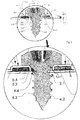
- Fig. 3 shows in enlarged detail of Fig. 2 the support portion 5.2 which protrudes downwardly from the upper portion 5.5 towards the structural element 2.
- the support portion 5.2 has a free end 5.2.1 which is oriented to abut essentially perpendicularly on the structural element 2. Due to said perpendicular orientation of its free end 5.2.1, the support portion 5.2 is axially stressed by the screw 4 and has thus a high stiffness that resists the force applied by the screw and effectively avoids that the screw flattens the support portion 5.2, thereby ensuring a screw connection that has a considerably enforced strength.
Landscapes
- Engineering & Computer Science (AREA)
- General Engineering & Computer Science (AREA)
- Mechanical Engineering (AREA)
- Connection Of Plates (AREA)
Priority Applications (6)
| Application Number | Priority Date | Filing Date | Title |
|---|---|---|---|
| EP15174955.3A EP3112701A1 (de) | 2015-07-02 | 2015-07-02 | Schraubverbindung |
| CN201680037396.4A CN107820548A (zh) | 2015-07-02 | 2016-06-13 | 螺钉连接 |
| US15/736,314 US20180355896A1 (en) | 2015-07-02 | 2016-06-13 | Screw connection |
| EP16732977.0A EP3317548B1 (de) | 2015-07-02 | 2016-06-13 | Schraubverbindung |
| AU2016287017A AU2016287017B2 (en) | 2015-07-02 | 2016-06-13 | Screw connection |
| PCT/EP2016/063533 WO2017001181A1 (en) | 2015-07-02 | 2016-06-13 | Screw connection |
Applications Claiming Priority (1)
| Application Number | Priority Date | Filing Date | Title |
|---|---|---|---|
| EP15174955.3A EP3112701A1 (de) | 2015-07-02 | 2015-07-02 | Schraubverbindung |
Publications (1)
| Publication Number | Publication Date |
|---|---|
| EP3112701A1 true EP3112701A1 (de) | 2017-01-04 |
Family
ID=53502554
Family Applications (2)
| Application Number | Title | Priority Date | Filing Date |
|---|---|---|---|
| EP15174955.3A Withdrawn EP3112701A1 (de) | 2015-07-02 | 2015-07-02 | Schraubverbindung |
| EP16732977.0A Not-in-force EP3317548B1 (de) | 2015-07-02 | 2016-06-13 | Schraubverbindung |
Family Applications After (1)
| Application Number | Title | Priority Date | Filing Date |
|---|---|---|---|
| EP16732977.0A Not-in-force EP3317548B1 (de) | 2015-07-02 | 2016-06-13 | Schraubverbindung |
Country Status (5)
| Country | Link |
|---|---|
| US (1) | US20180355896A1 (de) |
| EP (2) | EP3112701A1 (de) |
| CN (1) | CN107820548A (de) |
| AU (1) | AU2016287017B2 (de) |
| WO (1) | WO2017001181A1 (de) |
Families Citing this family (2)
| Publication number | Priority date | Publication date | Assignee | Title |
|---|---|---|---|---|
| US12434813B2 (en) | 2018-02-08 | 2025-10-07 | Vita Inclinata Ip Holdings Llc | Bidirectional thrust apparatus, system and method |
| US11441594B2 (en) | 2019-08-22 | 2022-09-13 | Haier Us Appliance Solutions, Inc. | Fastening assembly for a thin-walled part of an appliance |
Citations (5)
| Publication number | Priority date | Publication date | Assignee | Title |
|---|---|---|---|---|
| GB2067700A (en) * | 1980-01-18 | 1981-07-30 | Textron Inc | Threaded fastener and structural joint attained therewith |
| DE3622001A1 (de) * | 1986-07-01 | 1988-01-07 | Lautenschlaeger Kg Karl | Gewindeausbildung von befestigungsbohrungen in moebelbeschlaegen aus metallblech |
| DE3934589C1 (en) * | 1989-10-17 | 1991-04-25 | Audi Ag, 8070 Ingolstadt, De | Fastening metal component to plastics component - involves self-tapping screw passing through metal bush into bore in plastics |
| DE102013212038A1 (de) * | 2012-06-29 | 2014-01-02 | Canon K. K. | Befestigungsaufbau |
| US20140271030A1 (en) * | 2013-03-14 | 2014-09-18 | Canon Kabushiki Kaisha | Fastening material |
Family Cites Families (21)
| Publication number | Priority date | Publication date | Assignee | Title |
|---|---|---|---|---|
| US2275315A (en) * | 1939-01-12 | 1942-03-03 | Ray Reginald John | Means for attaching fragile bodies to a support |
| US2945524A (en) * | 1955-07-05 | 1960-07-19 | United Carr Fastener Corp | Sheet metal lock nut with deformable flange and sealing material |
| US3425473A (en) * | 1966-10-25 | 1969-02-04 | United Carr Inc | Washer-nut combination having a frangible connecting element |
| ZA725712B (en) * | 1971-09-01 | 1974-10-30 | Illinois Tool Works | Screw fasteners |
| US4193434A (en) * | 1978-08-10 | 1980-03-18 | Illinois Tool Works Inc. | Preassembled fastener unit for clamping plastic workpieces |
| US4238165A (en) * | 1979-01-25 | 1980-12-09 | Illinois Tool Works Inc. | Fastener unit for clamping plastic workpieces |
| US4306708A (en) * | 1979-05-14 | 1981-12-22 | Tennessee Bolt And Screw Co., Inc. | Means for establishing a support post for a grommet |
| JPS6224010A (ja) * | 1985-07-24 | 1987-02-02 | クラウン精密工業株式会社 | 薄肉金属板における螺子締結構造 |
| US5397206A (en) * | 1994-03-15 | 1995-03-14 | Chrysler Corporation | Vibration isolating fastener |
| US5489177A (en) * | 1994-06-08 | 1996-02-06 | Crest Products, Inc. | Fastener assembly with axially captivated washer |
| JP2003307208A (ja) * | 2002-02-13 | 2003-10-31 | Murata Mfg Co Ltd | ネジ固定具、それを用いた高周波機器およびその特性調整方法 |
| US7048265B2 (en) * | 2003-07-21 | 2006-05-23 | Basf Corporation | Two stage isolation mount assembly |
| JP2005240950A (ja) * | 2004-02-27 | 2005-09-08 | Kyocera Corp | ネジ締結構造 |
| FR2879269B1 (fr) * | 2004-12-14 | 2008-04-25 | Valeo Thermique Moteur Sas | Dispositif de fixation d'un elememt sur un support |
| JP2006177438A (ja) * | 2004-12-22 | 2006-07-06 | Meisei Kogyo Kk | 金属板の締結方法およびタッピングねじ |
| CN200989360Y (zh) * | 2006-10-17 | 2007-12-12 | 钟元 | 一种新型的螺丝固定结构 |
| JP2008128284A (ja) * | 2006-11-17 | 2008-06-05 | Calsonic Kansei Corp | 基板の共締め構造、検出用金具および締結状態検出方法 |
| US8800534B2 (en) * | 2011-11-18 | 2014-08-12 | Robert Bosch Gmbh | Fuel rail mounting arrangement |
| CN102606953A (zh) * | 2012-03-06 | 2012-07-25 | 深圳市华星光电技术有限公司 | 一种背光模组及液晶显示装置 |
| JP6192323B2 (ja) * | 2013-03-21 | 2017-09-06 | 日本パワーファスニング株式会社 | 建物用板材の取付け金具及び取付け装置、並びにこの金具を備えた建物 |
| DE102015101258A1 (de) * | 2014-01-28 | 2015-07-30 | Richard Bergner Verbindungstechnik Gmbh & Co. Kg | Verfahren zur Herstellung einer Montageeinheit und Befestigereinheit zur Durchführung des Verfahrens |
-
2015
- 2015-07-02 EP EP15174955.3A patent/EP3112701A1/de not_active Withdrawn
-
2016
- 2016-06-13 EP EP16732977.0A patent/EP3317548B1/de not_active Not-in-force
- 2016-06-13 WO PCT/EP2016/063533 patent/WO2017001181A1/en not_active Ceased
- 2016-06-13 CN CN201680037396.4A patent/CN107820548A/zh active Pending
- 2016-06-13 AU AU2016287017A patent/AU2016287017B2/en not_active Ceased
- 2016-06-13 US US15/736,314 patent/US20180355896A1/en not_active Abandoned
Patent Citations (5)
| Publication number | Priority date | Publication date | Assignee | Title |
|---|---|---|---|---|
| GB2067700A (en) * | 1980-01-18 | 1981-07-30 | Textron Inc | Threaded fastener and structural joint attained therewith |
| DE3622001A1 (de) * | 1986-07-01 | 1988-01-07 | Lautenschlaeger Kg Karl | Gewindeausbildung von befestigungsbohrungen in moebelbeschlaegen aus metallblech |
| DE3934589C1 (en) * | 1989-10-17 | 1991-04-25 | Audi Ag, 8070 Ingolstadt, De | Fastening metal component to plastics component - involves self-tapping screw passing through metal bush into bore in plastics |
| DE102013212038A1 (de) * | 2012-06-29 | 2014-01-02 | Canon K. K. | Befestigungsaufbau |
| US20140271030A1 (en) * | 2013-03-14 | 2014-09-18 | Canon Kabushiki Kaisha | Fastening material |
Also Published As
| Publication number | Publication date |
|---|---|
| CN107820548A (zh) | 2018-03-20 |
| US20180355896A1 (en) | 2018-12-13 |
| AU2016287017A1 (en) | 2017-11-23 |
| EP3317548A1 (de) | 2018-05-09 |
| WO2017001181A1 (en) | 2017-01-05 |
| AU2016287017B2 (en) | 2020-04-09 |
| EP3317548B1 (de) | 2020-08-26 |
Similar Documents
| Publication | Publication Date | Title |
|---|---|---|
| US7568870B2 (en) | Push nut | |
| US7144181B2 (en) | Joining device and kitchen appliance fitted with the joining device | |
| US9109620B2 (en) | Fastener | |
| EP2604871A2 (de) | Selbststanzende Mutter | |
| EP3317548B1 (de) | Schraubverbindung | |
| JPH11241714A (ja) | 素材、板状構成要素への素材取付け方法、構成要素アッセンブリーおよびダイスボタン | |
| EP1262670B1 (de) | Anordnung aus einem Befestigungselement und einer Unterlegscheibe | |
| US20120048258A1 (en) | Adjustable grate foot for home appliance | |
| CN101504023B (zh) | 一种铆合连接件 | |
| AU2016351942B2 (en) | Rotary knob assembly and electric oven | |
| CN206922567U (zh) | 电机减振垫、机座组件和料理机 | |
| KR20170102498A (ko) | 토크를 플라스틱제 케이스로 유도하기 위한 금속제 고정 부재 | |
| CN204572720U (zh) | 一种压铆螺母 | |
| CN206820591U (zh) | 电机减振垫、机座组件和料理机 | |
| EP2756124B1 (de) | Elektrisches Haushaltsgerät umfassend eine elastische Befestigungsvorrichtung | |
| EP3390846B1 (de) | Kochherd | |
| US2760540A (en) | Headed screw fastener and resilient sheet metal retainer therefor | |
| CN109004788A (zh) | 电机减振垫、机座组件和料理机 | |
| CN206922568U (zh) | 电机减振垫、机座组件和料理机 | |
| KR20080105290A (ko) | 와셔 형상의 플랜지 볼트 | |
| CA2547499C (en) | System for affixing a grip handle to a container of an item of cookware | |
| CN217524781U (zh) | 外壳固定结构及煎烤机 | |
| WO2014087309A1 (en) | Fastening device, fastening system, washing machine with fastening system, and method for manufacture of fastening device | |
| JP4824120B2 (ja) | スペーサ | |
| CN207766590U (zh) | 线圈盘以及电磁加热烹饪装置 |
Legal Events
| Date | Code | Title | Description |
|---|---|---|---|
| PUAI | Public reference made under article 153(3) epc to a published international application that has entered the european phase |
Free format text: ORIGINAL CODE: 0009012 |
|
| AK | Designated contracting states |
Kind code of ref document: A1 Designated state(s): AL AT BE BG CH CY CZ DE DK EE ES FI FR GB GR HR HU IE IS IT LI LT LU LV MC MK MT NL NO PL PT RO RS SE SI SK SM TR |
|
| AX | Request for extension of the european patent |
Extension state: BA ME |
|
| STAA | Information on the status of an ep patent application or granted ep patent |
Free format text: STATUS: THE APPLICATION HAS BEEN WITHDRAWN |
|
| 18W | Application withdrawn |
Effective date: 20170112 |