EP3112824B1 - Dispositif et procede de determination d'une taille caracteristique d'un objet - Google Patents
Dispositif et procede de determination d'une taille caracteristique d'un objet Download PDFInfo
- Publication number
- EP3112824B1 EP3112824B1 EP16173923.0A EP16173923A EP3112824B1 EP 3112824 B1 EP3112824 B1 EP 3112824B1 EP 16173923 A EP16173923 A EP 16173923A EP 3112824 B1 EP3112824 B1 EP 3112824B1
- Authority
- EP
- European Patent Office
- Prior art keywords
- signal
- input signal
- frequency
- baseband
- filter
- Prior art date
- Legal status (The legal status is an assumption and is not a legal conclusion. Google has not performed a legal analysis and makes no representation as to the accuracy of the status listed.)
- Active
Links
Images




Classifications
-
- G—PHYSICS
- G01—MEASURING; TESTING
- G01N—INVESTIGATING OR ANALYSING MATERIALS BY DETERMINING THEIR CHEMICAL OR PHYSICAL PROPERTIES
- G01N22/00—Investigating or analysing materials by the use of microwaves or radio waves, i.e. electromagnetic waves with a wavelength of one millimetre or more
- G01N22/04—Investigating moisture content
-
- G—PHYSICS
- G01—MEASURING; TESTING
- G01G—WEIGHING
- G01G17/00—Apparatus for or methods of weighing material of special form or property
-
- G—PHYSICS
- G01—MEASURING; TESTING
- G01G—WEIGHING
- G01G9/00—Methods of, or apparatus for, the determination of weight, not provided for in groups G01G1/00 - G01G7/00
- G01G9/005—Methods of, or apparatus for, the determination of weight, not provided for in groups G01G1/00 - G01G7/00 using radiations, e.g. radioactive
-
- G—PHYSICS
- G01—MEASURING; TESTING
- G01N—INVESTIGATING OR ANALYSING MATERIALS BY DETERMINING THEIR CHEMICAL OR PHYSICAL PROPERTIES
- G01N33/00—Investigating or analysing materials by specific methods not covered by groups G01N1/00 - G01N31/00
- G01N33/15—Medicinal preparations ; Physical properties thereof, e.g. dissolubility
Definitions
- Embodiments of the present invention generally relate to devices and methods for determining variables characteristic of an object, such as a mass and / or a moisture content of the object.
- Such methods and / or devices can be used, for example, in the industrial mass production of drugs.
- portioned drugs for example in the form of tablets, serve as the object.
- other areas of application are also possible in which high speeds are important when determining variables that are characteristic of an object.
- Tablets will remain the most important form of drug delivery for the foreseeable future.
- the demands on their production are increasing noticeably: Increased competition and cost pressure have brought the issue of efficiency to the fore.
- the production of new, complex preparations must be accordingly quality-oriented and efficient - and that with an increasing number of production changes.
- High-speed tableting with an output of more than 1.6 million tablets per hour is currently the benchmark for productivity in tableting.
- pharmaceutical manufacturers must ensure high quality standards at all locations in order to meet the guidelines of the control authorities. This makes a 100% product inspection necessary. This results in very high measuring speeds as a requirement for measuring systems, with at the same time the least possible or, better still, no influence on the mass flow transport.
- the U.S. 6,163,158 describes a concept for detecting at least one property of a substance by evaluating the detuning of an RF resonator caused by the presence of the substance, to which microwaves are supplied and from which a high-frequency signal influenced by the substance is picked up, its resonance frequency shift and attenuation a signal that is not influenced by the substance is detected, the resonator being supplied with microwaves with at least two different frequencies.
- the shifts in the resonance frequency are recorded by comparing the resonance curves of the resonator that are unaffected and influenced by the substance.
- the attenuation is recorded by comparing the amplitudes of the resonance curves at the frequencies of the supplied microwaves.
- exemplary embodiments create a device for determining a variable that is characteristic of an object.
- the device comprises a signal generation unit which is designed to generate an input signal.
- the device further comprises a high-frequency filter with an input for the input signal, an output for an output signal and with an area, for example a surface, for an interaction between an electromagnetic stray field of the high-frequency filter and the object.
- a signal evaluation unit is provided which is designed to convert the input signal and the output signal of the High frequency filter to determine a transmission characteristic of the high frequency filter as a measure for the characteristic size of the object.
- the transfer characteristic can include a transfer function of the high-frequency filter and / or a signal propagation time through the high-frequency filter.
- Embodiments are therefore based on the idea of determining the characteristic size of the object from an influencing of the transmission characteristic of the high-frequency filter that is characteristic of the object.
- the object is located on or directly on a surface of the high-frequency filter.
- the latter can be designed, for example, as a cavity or coaxial resonator.
- the surface of the filter for interaction with the measurement object can, for example, be a side of a filter housing that is as transparent as possible for electromagnetic radiation, e.g. comprise a ceramic surface or other suitable material.
- a transport device can additionally be provided which is designed to guide the object along the surface of the high-frequency filter.
- transport devices are pipes or channels in which the object can be guided past the surface of the high-frequency filter at a comparatively high speed in order to briefly interact with its stray electromagnetic field.
- the filter surface can be part of the transport device, e.g. form a pipe or gutter wall. High mass flow transport speeds, that is to say high production speeds, can thus be achieved.
- Other examples of transport devices also include conveyor belts or the like.
- the transport device is preferably designed to move the object along the surface of the high-frequency filter in direct contact with the surface.
- the object is in touching contact with the surface of the filter, for example by rolling over it or being pushed over it. By touching it, particularly precise measurement results can be achieved for the characteristic variable.
- the characteristic variable can include a mass and / or moisture content of the object. From the transmission characteristic of the high-frequency filter changed by the object, conclusions can be drawn about the mass and / or moisture of the object being passed. Other characteristic quantities, e.g. Size, shape, etc. are of course also conceivable.
- the object itself can contain at least one portioned solid unit, e.g. a tablet, a capsule, etc.
- at least one portioned solid unit e.g. a tablet, a capsule, etc.
- the signal evaluation unit can be designed to determine the transmission characteristic by ascertaining a transit time or phase difference between the input signal and the output signal.
- the phase difference can then be used as a measure for the characteristic size of the object. This can advantageously lead to high sensitivities and thus high measuring accuracies.
- the signal generation unit is designed to provide the input signal with a (carrier) frequency in a frequency range from 300 MHz to 300 GHz. Depending on the embodiment, this can be a mono-frequency or a broadband input signal.
- the signal generation unit can be designed to generate the input signal for the high-frequency filter by mixing a baseband input signal with a high-frequency carrier signal in the pass band of the high-frequency filter.
- the high-frequency filter can therefore be designed as a band pass.
- the signal generation unit can be designed to provide the carrier signal with a carrier frequency in a frequency range from 300 MHz to 300 GHz.
- the carrier frequency can for example be selected as a function of a signal bandwidth of the baseband input signal - the larger its bandwidth, the higher the carrier frequency.
- the signal generation unit is designed to generate the baseband input signal with a signal bandwidth of at least 10 MHz produce. This is not just a carrier signal with a discrete carrier frequency, but a comparatively broadband signal modulated onto the carrier frequency.
- the resulting spectral range of the transmission characteristic which encompasses a plurality of frequencies, enables a high level of measurement accuracy to be achieved.
- the amplitude and / or phase response for the entire signal bandwidth or a part thereof, including a plurality of frequencies, can be evaluated as an object characteristic.
- OFDM orthogonal frequency division multiplexing
- the broadband baseband input signal can already be an OFDM signal in the baseband.
- other suitable baseband signals are also possible, e.g. Pseudo-random sequences.
- the signal generation unit can be designed to weight the baseband input signal by means of a window function, in particular a Tuckey window function.
- a window function in particular a Tuckey window function.
- other suitable window functions can also be used to limit the band.
- the signal evaluation unit can be designed to generate a baseband output signal by mixing the output signal with the carrier signal and to determine the transmission characteristic from the baseband input signal and the baseband output signal. By determining the transmission characteristics in the baseband range, complex and costly RF circuit arrangements can be dispensed with.
- the signal evaluation unit can be designed to determine the transmission characteristic by dividing the baseband output signal and the baseband input signal or their respective frequency spectra.
- the signal evaluation unit can be designed to determine the transmission characteristic by a phase comparison between the baseband output signal and the baseband input signal. This can be implemented, for example, by means of a digital signal processor (DSP) or a field programmable gate array (FPGA).
- DSP digital signal processor
- FPGA field programmable gate array
- the signal evaluation unit can be designed to compare the transmission characteristic with a reference transmission characteristic predetermined for the object and to output an error message if a difference between the transmission characteristic and the reference transmission characteristic is above a threshold value. This enables faulty objects to be sorted out efficiently.
- inventions create a device for determining a variable that is characteristic of at least one tablet.
- the device comprises a baseband signal generation unit which is designed to generate a baseband input signal with a signal bandwidth of at least 10 MHz, a high-frequency carrier signal generation unit which is designed to generate a carrier signal in a frequency range from 300 MHz to 300 GHz, a mixer unit which is designed is to generate from the baseband input signal and the carrier signal high frequency input signal and a high frequency filter with an input for the high frequency input signal, an output for a high frequency output signal and with a filter surface.
- a transport device which is designed to move the at least one tablet past the surface of the high-frequency filter for an interaction between an electromagnetic stray field of the high-frequency filter and the at least one tablet.
- the mixer unit is designed to generate a baseband output signal from the high-frequency output signal and the carrier signal.
- the device also comprises a signal evaluation unit, which is designed to determine from the baseband input signal and the baseband output signal a transmission characteristic of the high-frequency filter comprising a plurality of frequencies as a measure for the characteristic size of the at least one tablet.
- exemplary embodiments create methods for determining a variable that is characteristic of an object.
- the method comprises generating an input signal for a high frequency filter; producing an interaction between the object and a stray electromagnetic field of the high-frequency filter caused by the input signal, and determining, from the input signal and an output signal of the high-frequency filter, a transmission characteristic of the high-frequency filter as a measure of the characteristic variable.
- establishing the interaction includes moving the object along the surface of the high-frequency filter, in particular moving it in a touching manner.
- the transmission characteristic can be determined by determining a transit time or phase difference between the input signal and the output signal. Additionally or alternatively, the transfer characteristic can be determined by determining a transfer function for a frequency range comprising a plurality of frequencies.
- a mass of the object can be determined as a characteristic variable based on the transmission characteristic determined during the interaction between the object and the stray electromagnetic field and based on a reference transmission characteristic of the high-frequency filter without interaction between the object and the stray electromagnetic field of the high-frequency filter.
- the transmission characteristic determined during the interaction between the object and the stray electromagnetic field can be compared with a comparison with a setpoint transmission characteristic (or reference transmission characteristic) that applies to the object or the type of object. If a deviation of the measured transfer characteristic from the target transfer characteristic lies within a permissible tolerance range, the object, e.g. one or more tablets released for further processing. Otherwise an error message will appear.
- exemplary embodiments can be seen in the fact that they can easily be inserted into existing transport devices of tablet presses. There is no need for any technically complex and individual positioning of test bodies that would delay the transport stream. Furthermore, the proposed approach allows very high measurement rates to be achieved with fast digital signal processing.
- the Fig. 1 shows a block diagram of a device 100 for determining a mass and / or moisture content of portioned active ingredient units 102, such as tablets, capsules, coated tablets, etc.
- the device 100 comprises a signal generation unit 110, a high-frequency filter (RF filter) 120 coupled to the latter, and a signal evaluation unit 130 coupled therewith.
- the RF filter 120 has an input for an RF input signal 117 generated by the signal generation unit 110, an output for an HF output signal 121 filtered from the HF input signal 117 and a surface 122 for an interaction between an electromagnetic stray field of the HF filter 120 and the portioned active ingredient units 102.
- the output of the HF filter 120 can be connected or connected to an input of the signal evaluation unit 130 . connected.
- the portioned active ingredient units 102 are guided along the filter surface 122 in a touching manner by means of a transport device 140 at the highest possible speed.
- active ingredient units 102 and filter surface 122 are in contact with one another during the measurement.
- the transport device 140 can comprise, for example, a conveyor belt, a transport channel, a transport pipe or the like in order to bring the active ingredient units 102 into direct contact with the filter surface or filter housing surface 122.
- the RF filter 120 which is designed as a bandpass filter, can be implemented, for example, as a cavity or coaxial resonator. It can be designed for a center frequency of the RF input signal 117 in, for example, a range from 300 MHz to 300 GHz. Its pass band around the center frequency is, for example, at least 10 MHz, at least 50 MHz, or at least 100 MHz, corresponding to a bandwidth of the RF input signal 117.
- the filter surface 122 can, for example, be designed as a ceramic surface and be part of a transport tube or channel, by means of which the Active ingredient units 102 are guided past the HF filter 120 in a touching manner for the measurement.
- the RF filter 120 can be constructed in such a way that part of the electric field can penetrate the material to be measured. For this purpose, a surrounding filter housing can be open on one side or have a through opening.
- the signal generation unit 110 is designed to generate the RF input signal 117 for the RF filter 120 from a baseband input signal 113 with a low-pass behavior.
- the signal generation unit 110 comprises a baseband signal generation unit 112, which is designed to generate the baseband input signal 113 with a signal bandwidth of at least 10 MHz, at least 50 MHz, or at least 100 MHz.
- the signal bandwidth can be selected depending on the speed of the active ingredient units 102. The faster the active ingredient units 102 move, the larger the bandwidth should be selected. Conversely, the signal bandwidth can be smaller with slow movement.
- the baseband signal generation unit 112 may have digital-to-analog converters (D / A converters) in order to generate an analog baseband signal from a digital baseband signal.
- the baseband signal generation unit 112 can comprise, for example, one or more programmable hardware components such as DSPs, ASICs, or FPGAs for generating the baseband input signal 113.
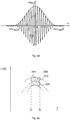
- the baseband input signal 113 can be one with a window function, e.g. a Tuckey window function, weighted baseband signal.
- the quantities ⁇ m and ⁇ denote the center frequency or the bandwidth of the signal.
- the Tuckey weighting is characterized by a good combination between frequency and time behavior. Typical bandwidths can be a few hundred MHz.
- the center frequency ⁇ m can be selected almost as desired by frequency conversion, but preferably in a range from 300 MHz to 300 GHz.
- the spectrum and time profile of the measurement signal 113 or 117 can be specified analytically.
- F. N ⁇ ⁇ 1 2 ⁇ 1 + cos 2 ⁇ ⁇ - ⁇ m ⁇ For ⁇ - ⁇ m ⁇ ⁇ ⁇ 2 0 otherwise
- FM chirps or multi-carrier signals (e.g. OFDM signals) can of course also be used.
- multi-carrier signals e.g. OFDM signals
- the signal generation unit 110 also has a high frequency carrier signal generation unit 114 which is designed to generate an RF carrier signal 115, for example in a frequency range from 300 MHz to 300 GHz to generate.
- the high-frequency carrier signal generation unit 114 can comprise an oscillator circuit.
- an up-conversion unit 116 is provided in the signal generation unit 110 for frequency conversion, which is designed to generate the broadband and band-limited RF input signal 117 for the RF filter 120 from the broadband and band-limited baseband input signal 113 and the RF carrier signal 115.
- the band-limited RF signal 117 obtained in this way can then be passed to the test arrangement with the RF filter 120 after appropriate conditioning (amplification, adaptation, possibly filtering, etc.).
- an electromagnetic field is created in the HF filter 120 and in its surroundings.
- the active ingredient units 102 passed along the filter surface influence this electromagnetic field in a characteristic manner for the active ingredient units and thus change a transmission characteristic of the HF filter 120, such as its amplitude response (magnitude frequency response) and / or phase response (phase frequency response).
- the changed transmission characteristic of the RF filter 120 as a measure e.g. the signal evaluation unit 130 can determine the mass and / or moisture of the active ingredient units 102.
- the signal 121 filtered by the test arrangement can also be received in the time domain.
- an optional down-mixer unit 136 is provided in the illustrated embodiment in order to generate an intermediate-frequency or baseband output signal 137 with manageable frequencies from the HF output signal 121 and the HF carrier signal 115 of the high-frequency carrier signal generation unit 114.
- the down-conversion unit 136 could also be dispensed with.
- the signal evaluation unit 130 is designed to determine from the baseband input signal (reference signal) 113 and the baseband output signal (received signal) 137 a transmission characteristic of the RF filter 120 as a measure for the characteristic variable (mass / moisture) of the active ingredient units 102.
- the two (analog) baseband signals 113 and 137 can be fed to an analog-to-digital converter (A / D converter) 132 before a digital signal processing unit 134, e.g. in the form of an FPGA, carries out digital signal processing of the resulting digital baseband signals.
- the signal evaluation unit 130 could also include a memory for the known baseband input signal (reference signal) 113. The desired information is obtained e.g. by dividing the received spectrum by the reference spectrum within the measurement bandwidth.
- the measurement bandwidth of the signal 113 or 117 can be several 100 MHz.
- the measurement time can easily be reduced to less than 1 ⁇ s with modern FPGAs.
- the digital signal processing unit 134 can use the digitized signals 113 and 137 to determine the transfer function H (f) of the filter 120 over a frequency range with a plurality of frequencies at short time intervals .
- These discrete values do not have to have recorded the precise point in time at which an active ingredient unit 102 was at the location of the highest measurement sensitivity. Therefore, from the discrete measured values and a known sensitivity curve of the HF filter 120, the maximum change in the transfer function can be calculated. This determined point of greatest influence on the transfer function can serve as a measure for the mass of the active ingredient units 102.
- a mass of an active ingredient unit 102 can be determined directly or indirectly as a characteristic variable based on the transfer characteristic determined during the interaction between the active ingredient unit 102 and the electromagnetic stray field and based on a reference transfer characteristic of the HF filter 120.
- This reference transfer characteristic can be calibrated beforehand with test specimens whose mass is precisely known. For example, a certain amount of a tablet type to be measured can first be precisely weighed out. The variations in the weights of the test tablets can be selected to be greater than the mass range in which the active ingredient units 102 later declared as “good” lie.
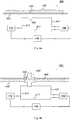
- Figure 2b shows schematically the course of a reference transmission characteristic 210 obtained by pre-calibration with known mass units in a frequency band from a lower frequency f u to an upper frequency f o . Furthermore, a tolerance range 220 with absolute lower and upper limits 222, 224 is shown.
- a transfer characteristic measured during the interaction between the active ingredient units 102 and the electromagnetic stray field can now be compared with the setpoint or reference transfer characteristic 210 applicable to the active ingredient unit 102. If the measured transfer characteristic deviates from the desired transfer characteristic 210 within the permissible tolerance range 220, an active ingredient unit 102 is released for further processing. Otherwise an error message will appear.
- the Fig. 3 shows a schematic flow diagram of a method 300 which can carry out the described measuring arrangement 100.
- the method 300 includes generating 310 an input signal 113, 117 for the RF filter 120.
- a baseband input signal 113 with a signal bandwidth of at least 10 MHz, at least 50 MHz, or at least 100 MHz can be used be generated.
- a carrier signal 115 can be generated in a frequency range of, for example, 300 MHz to 300 GHz.
- a broadband high-frequency input signal 117 for the filter 120 can then be generated from the baseband input signal 113 and the carrier signal 115.
- the method 300 further comprises producing 320 an interaction between at least one active substance unit 102 and a stray electromagnetic field of the HF filter 120 caused by the input signal 117.
- the at least one active substance unit 102 can be on the surface 122 of the HF filter 120 for an interaction between the electromagnetic stray field of the HF filter 120 and the at least one active ingredient unit 102, for example be passed by touching.
- the method 300 also includes determining 330 a transmission characteristic of the HF filter 120 as a measure for the characteristic variable from the input signal 113, 117 and an output signal 121, 137 of the HF filter 120.
- a baseband output signal 137 can be generated from the RF output signal 121 and the carrier signal 115, for example. From the baseband input signal 113 and the baseband output signal 137, a transmission characteristic of the RF filter 120 can be determined as a measure for the characteristic variable of the at least one active ingredient unit 102.
- the mass of the at least one active ingredient unit 102 can now be determined.
- the measured transfer characteristic can be compared with a reference transfer characteristic valid for the at least one active ingredient unit 102.
- This reference transmission characteristic can be calibrated in advance, for example. If a deviation of the measured transfer characteristic from the target transfer characteristic lies within a permissible tolerance range, the at least one active agent unit 102, e.g. one or more tablets released for further processing. Otherwise an error message can be issued.
- the transfer function can describe the transmission properties or the reflection properties of the test arrangement.
- the transmitted and received signals are compared with one another. This can be done, for example, by determining the respective spectra of the two signals 113 and 137 by Fourier transformation.
- the transfer function H (f) can be obtained by dividing the two spectra. In practice, the division is limited to the signal bandwidth in order to avoid division by 0.
- the device 400 again comprises a signal generation unit 410, a high-frequency filter (RF filter) 420 coupled to the latter, and a signal evaluation unit 430 coupled therewith.
- the RF filter 420 has an input for an RF input signal 417 generated by the signal generation unit 410, an output for a filtered HF output signal 421 and a (closed or open) surface 422 for an interaction between an electromagnetic stray field of the HF filter 420 and the portioned active ingredient units 402.
- the output of the HF filter 420 is connected to an input of the signal evaluation unit 430.
- the signal generation unit 410 is designed to generate an input signal 417 for the RF filter 420.
- the input signal 417 can be a mono-frequency HF signal, for example the carrier signal 115, act.
- the signal evaluation unit 130 is designed to determine from the input signal 417 and the output signal 421 of the HF filter 420 a transmission characteristic in the form of a transit time difference between the signals 417 and 421 as a measure for the characteristic size of the portioned active ingredient units 102.
- a mass flow 402 is conducted past the HF filter 420.
- the measurement can again take place in a touching manner.
- the HF filter 420 can, for example, be built into a housing that is open on one side.
- the HF filter 420 can be mounted under the net and the measurement can be carried out through the net.
- a ceramic surface or the like can also be used instead of the open housing.
- the RF or microwave signal 417 is generated in the signal generation unit 410 and fed in parallel to the RF filter 420 and the signal evaluation unit 430.
- the phase difference between the filter output signal 421 and the input signal 417 can be formed by that of the signal generation unit 410.
- the frequency of the signal generation unit 410 or the input signal 417 generated by it can be readjusted via a suitably set controller 435 such that the frequency of the input signal 417 is at the maximum of the transfer function of the filter structure.
- the point of maximum slope of the measured curve for the phase difference can be used as a criterion for this.
- Fig. 5 a possible profile of the measured phase difference of the RF filter 420 can be seen.
- the frequency is plotted on the horizontal axis and the phase difference on the vertical axis.
- the curve shows a possible course of the phase difference with the point of greatest slope at 510.
- the mass flow 402 is passed through a sensor head 420 ', the measurement also takes place in a touching manner.
- the sensor head 420 ' comprises a suitably selected filter structure that can be built into a housing with a through opening.
- the measurement is carried out in the same way as the setup from Figure 4a .
- the mass is transported through a suitable pipe 440, for example.
- the Fig. 6 shows a schematic flow diagram of a method 600 which the measuring arrangement 400 can carry out.
- the method 600 comprises generating 610 an input signal 417 for the RF filter 420.
- an RF signal with a (discrete) frequency of e.g. 300 MHz to 300 GHz can be generated.
- the method 600 further comprises producing 620 an interaction between at least one active ingredient unit 402 and a stray electromagnetic field of the RF filter 420 caused by the input signal 417.
- the at least one active ingredient unit 402 on the surface 422 of the RF filter 420 for an interaction between the electromagnetic stray field of the HF filter 420 and the at least one active ingredient unit 102 for example be passed by touching.
- the method 600 also includes determining 630 a transmission characteristic of the RF filter 420 as a measure for the characteristic variable based on the input signal 417 and an output signal 421 of the RF filter 420.
- a transmission characteristic of the RF filter 420 as a measure for the characteristic variable based on the input signal 417 and an output signal 421 of the RF filter 420.
- the phases of the RF signals 417 and 421, or the Phases of signals derived therefrom The greater the influence of the mass flow 402 on the signal transit time through the filter 420, the greater the phase difference will turn out as a characteristic measure for the mass flow 402.
- embodiments of the present invention relate to a concept for measuring the mass and / or moisture of tablets or other portioned solid units by contact measurement with a high-frequency filter structure.
- the tablets or portioned solid units can be guided over the surface of a high-frequency filter at high speed.
- the presence of materials in the area of the stray field causes a changed phase shift and / or changed attenuation of the signal chain.
- This change in the transfer function of the high-frequency filter or the signal propagation time through the filter caused by the mass flow can be used to deduce the mass and / or the moisture content of the tablets or other portioned solid units.
- the transfer function of several signal components of a certain amplitude and frequency, that is to say a broadband signal, are modulated onto a high-frequency carrier, the frequency of which is in the pass band of the filter.
- the modulated carrier is passed through the filter and then demodulated and the resulting signals digitized.
- the transfer function of the high-frequency filter can be calculated from the digitized signals by digital signal processing. Both the modulation and the digital signal processing can take place with such a high bandwidth, for example 200 MHz, that the mechanical movement of the tablets or the portioned solid units is very slow in comparison. This means that even at very high transport speeds through the field of the high-frequency filter, a tablet or portioned solid unit is measured several times.
- the presence of material in the area of the stray field causes a change in the transit time through the high-frequency filter structure.
- the signal is fed to a detector through the filter structure from the generator and the signal is fed directly from the signal generation unit as a reference. This signal does not need to be broadband here.
- the detector evaluates a phase difference between the two signals.
- the signal frequency of the signal generation unit can now be readjusted via a suitably set controller so that the frequency lies at the point of the maximum slope of the measured curve for the phase difference.
- the frequency of the signal supplied by the generator is now a measure of the sum of the dielectric properties of the substance to be measured. Since the frequency can be measured very precisely, a high level of measurement accuracy is achieved. By appropriately dimensioning the controller, a high measurement speed can also be achieved.
- a major advantage here is the high sensitivity and thus high measurement accuracy.
- aspects have been described in connection with a device, it goes without saying that these aspects also represent a description of the corresponding method, so that a block or a component of a device is also to be understood as a corresponding method step or as a feature of a method step. Analogously, aspects that have been described in connection with or as a method step also represent a description of a corresponding block or details or features of a corresponding device.
- exemplary embodiments of the present invention can be implemented in hardware or in software.
- the implementation can be carried out using a digital storage medium such as a floppy disk, a DVD, a Blu-Ray disk, a CD, a ROM, a PROM, an EPROM, an EEPROM or a FLASH memory, a hard disk or other magnetic memory or optical memory, on which electronically readable control signals are stored, which can interact or cooperate with a programmable hardware component in such a way that the respective method is carried out.
- a digital storage medium such as a floppy disk, a DVD, a Blu-Ray disk, a CD, a ROM, a PROM, an EPROM, an EEPROM or a FLASH memory, a hard disk or other magnetic memory or optical memory, on which electronically readable control signals are stored, which can interact or cooperate with a programmable hardware component in such a way that the respective method is carried out.
- the digital storage medium can therefore be machine or computer readable.
- Some exemplary embodiments thus include a data carrier that has electronically readable control signals that are able to interact with a programmable computer system or a programmable hardware component in such a way that one of the methods described herein is carried out.
- An embodiment is thus a data carrier (or a digital storage medium or a computer-readable medium) on which the program for performing one of the methods described herein is recorded.
- embodiments of the present invention can be implemented as a program, firmware, computer program or computer program product with a program code or as data, wherein the program code or the data is effective or are to carry out one of the methods when the program is on a processor or a programmable hardware component runs.
- the program code or the data can, for example, also be stored on a machine-readable carrier or data carrier.
- the program code or the data can be present as source code, machine code or bytecode, as well as other intermediate code, among other things.
- a program can implement one of the methods while it is being carried out, for example, by reading out memory locations or writing data or several data into them, which may result in switching operations or other operations in transistor structures, in amplifier structures or in other electrical, optical, magnetic or components working according to another functional principle. Accordingly, data, values, sensor values or other information can be recorded, determined or measured by a program by reading out a memory location.
- a program can therefore acquire, determine or measure quantities, values, measured quantities and other information by reading out one or more memory locations, and by writing to one or more memory locations it can cause, initiate or carry out an action and control other devices, machines and components .
Landscapes
- Health & Medical Sciences (AREA)
- Physics & Mathematics (AREA)
- General Physics & Mathematics (AREA)
- Life Sciences & Earth Sciences (AREA)
- Chemical & Material Sciences (AREA)
- General Health & Medical Sciences (AREA)
- Biochemistry (AREA)
- Engineering & Computer Science (AREA)
- Pathology (AREA)
- Immunology (AREA)
- Analytical Chemistry (AREA)
- Pharmacology & Pharmacy (AREA)
- Food Science & Technology (AREA)
- Medicinal Chemistry (AREA)
- Bioinformatics & Cheminformatics (AREA)
- Toxicology (AREA)
- Molecular Biology (AREA)
- Biophysics (AREA)
- Electromagnetism (AREA)
- Investigating Or Analysing Materials By Optical Means (AREA)
Claims (11)
- Appareil (100) pour déterminer une caractéristique variable d'un objet (102), comprenant :une unité de génération de signal (110) configurée pour générer un signal d'entrée (113 ; 117);un filtre haute fréquence (120) avec une entrée pour le signal d'entrée (113 ; 117;), une sortie pour un signal de sortie (121 ; 137), et avec une région (122) pour une interaction entre un champ de dispersion électromagnétique du filtre haute fréquence (120) et l'objet (102) ; etune unité d'évaluation de signal (130) configurée pour utiliser le signal d'entrée (113 ; 117) et le signal de sortie (121 ; 137) du filtre haute fréquence pour déterminer une caractéristique de transmission du filtre haute fréquence comme mesure de la taille caractéristique de l'objet (102),caractérisé par le fait quel'unité de génération de signal (110) est configurée pour générer le signal d'entrée (117) en mélangeant un signal d'entrée en bande de base (113) avec un signal porteur (115) dans la bande passante du filtre haute fréquence (120),l'unité de génération de signal (110) est configurée pour générer le signal d'entrée en bande de base (113) avec une largeur de bande de signal d'au moins 10 MHz,etl'unité d'évaluation de signal (130) est configurée pour générer un signal de sortie en bande de base (137) en mélangeant le signal de sortie (121) avec le signal porteur (115) et pour déterminer la caractéristique de transmission sur la base du signal d'entrée en bande de base (113) et du signal de sortie en bande de base (137).
- Appareil (100) selon la revendication 1, comprenant en outre :
un dispositif de transport (140) configuré pour déplacer l'objet (102) le long d'une surface (122) du filtre haute fréquence. - Appareil (100) selon la revendication 2, dans lequel le dispositif de transport (140) est configuré pour déplacer l'objet (102) le long de la surface d'une manière en contact de surface (122).
- Appareil (100) selon l'une des revendications précédentes dans lequel l'unité d'évaluation de signal (130) est configurée pour établir la caractéristique de transmission en déterminant une différence de phase entre le signal d'entrée (113 ; 117) et le signal de sortie (121 ; 137).
- Appareil (100) selon l'une des revendications précédentes, dans lequel l'unité de génération de signal (110) est configurée pour fournir le signal d'entrée (117) avec une fréquence porteuse dans une gamme de fréquences allant de 300 MHz à 300 GHz.
- Appareil (100) selon l'une des revendications précédentes, dans lequel l'unité de génération de signal (110) est configurée pour pondérer le signal d'entrée en bande de base (113) au moyen d'une fonction fenêtre, en particulier une fonction fenêtre Tuckey.
- Appareil (100) selon l'une des revendications précédentes, dans lequel l'unité d'évaluation de signal (130) est configurée pour déterminer la caractéristique de transmission pour une gamme de fréquences comprenant une pluralité de fréquences.
- Appareil (100) selon l'une des revendications précédentes, dans lequel l'unité d'évaluation de signal (130) est configurée pour comparer la caractéristique de transmission avec une caractéristique de transmission de référence prédéterminée pour l'objet (102) et pour émettre un message d'erreur si une différence entre la caractéristique de transmission et la caractéristique de transmission de référence est supérieure à une valeur-seuil.
- Appareil (100) selon l'une des revendications précédentes, dans lequel l'objet (102) comprend au moins un comprimé et la variable caractéristique est une masse et/ou une humidité du au moins un comprimé.
- Procédé (300) pour déterminer une variable qui est caractéristique d'un objet (102), comprenant le fait de :générer (310) un signal d'entrée pour un filtre haute fréquence ;produire (320) une interaction entre l'objet et un champ de dispersion électromagnétique du filtre haute fréquence provoqué par le signal d'entrée ;déterminer (330), à partir du signal d'entrée et d'un signal de sortie du filtre haute fréquence, une caractéristique de transmission du filtre haute fréquence en tant que mesure de la taille caractéristique,caractérisé par le fait quele signal d'entrée (117 ; 417) est généré en mélangeant un signal d'entrée en bande de base (113) avec un signal porteur (115) dans la bande passante du filtre haute fréquence d,le signal d'entrée en bande de base (113) est généré avec une largeur de bande de signal d'au moins 10 MHz,le signal de sortie (121) est mélangé avec le signal porteur (115) pour générer un signal de sortie en bande de base, etla caractéristique de transmission est déterminée à partir du signal d'entrée en bande de base (113) et du signal de sortie en bande de base (137).
- Procédé (300) selon la revendication 10, dans lequel produire (320) l'interaction comprend le déplacement de l'objet le long de la surface du filtre haute fréquence.
Applications Claiming Priority (1)
| Application Number | Priority Date | Filing Date | Title |
|---|---|---|---|
| DE102015110491.1A DE102015110491B3 (de) | 2015-06-30 | 2015-06-30 | Vorrichtung, verfahren zur ermittlung einer für ein objekt charakteristischen grösse |
Publications (2)
| Publication Number | Publication Date |
|---|---|
| EP3112824A1 EP3112824A1 (fr) | 2017-01-04 |
| EP3112824B1 true EP3112824B1 (fr) | 2020-09-30 |
Family
ID=56551780
Family Applications (1)
| Application Number | Title | Priority Date | Filing Date |
|---|---|---|---|
| EP16173923.0A Active EP3112824B1 (fr) | 2015-06-30 | 2016-06-10 | Dispositif et procede de determination d'une taille caracteristique d'un objet |
Country Status (2)
| Country | Link |
|---|---|
| EP (1) | EP3112824B1 (fr) |
| DE (1) | DE102015110491B3 (fr) |
Families Citing this family (2)
| Publication number | Priority date | Publication date | Assignee | Title |
|---|---|---|---|---|
| DE102018111944A1 (de) * | 2018-05-17 | 2019-11-21 | Endress+Hauser SE+Co. KG | Messgerät zur Bestimmung eines Dielektrizitätswertes |
| DE102019113219A1 (de) | 2019-05-20 | 2020-11-26 | Deutsche Post Ag | Sensoreinrichtung zum Erkennen aufeinanderfolgender Objekte |
Family Cites Families (7)
| Publication number | Priority date | Publication date | Assignee | Title |
|---|---|---|---|---|
| US4223751A (en) * | 1979-03-26 | 1980-09-23 | Modern Controls, Inc. | High speed capacitance apparatus for classifying pharmaceutical capsules |
| US5602485A (en) * | 1996-01-16 | 1997-02-11 | Modern Controls, Inc. | Apparatus for screening capsules using velocity measurements |
| US6163158A (en) * | 1996-02-20 | 2000-12-19 | Hauni Maschinenbau Ag | Method of and apparatus for ascertaining at least one characteristic of a substance |
| US20060208194A1 (en) * | 2005-03-18 | 2006-09-21 | Voith Paper Patent Gmbh | Microwave mass measuring device and process |
| DE202006020481U1 (de) * | 2006-05-09 | 2008-08-21 | Ams Advanced Microwave Systems Gmbh | Mikrowellenmessvorrichtung zur Bestimmung mindestens einer Messgröße an einem Produkt |
| WO2008141833A1 (fr) * | 2007-05-22 | 2008-11-27 | Mediseal Gmbh | Dispositif de mesure de diélectricité |
| EP2251679B9 (fr) * | 2009-05-11 | 2013-01-09 | AMS- Advanced Microwave Systems GmbH | Dispositif et procédé de mesure d'une caractéristique de produit à l'aide d'un agencement de capteur de champ de dispersion à micro-ondes |
-
2015
- 2015-06-30 DE DE102015110491.1A patent/DE102015110491B3/de active Active
-
2016
- 2016-06-10 EP EP16173923.0A patent/EP3112824B1/fr active Active
Non-Patent Citations (1)
| Title |
|---|
| None * |
Also Published As
| Publication number | Publication date |
|---|---|
| EP3112824A1 (fr) | 2017-01-04 |
| DE102015110491B3 (de) | 2016-08-18 |
Similar Documents
| Publication | Publication Date | Title |
|---|---|---|
| DE69729117T2 (de) | Gerät zur Bestimmung des Feuchtigkeitsgehalts eines Materials | |
| EP3308110B1 (fr) | Procédé et dispositif pour contrôler la fonctionnalité d'un appareil de mesure du niveau de remplissage basé sur un radar | |
| EP2867693B1 (fr) | Procédé de mesure de distance et dispositif de mesure de distance | |
| DE102014008670A1 (de) | Radarkalibrierungssystem für fahrzeuge | |
| DE3940404C2 (de) | Verfahren und Gerät zur Dopplereffekt-Geschwindigkeitsmessung | |
| DE102015107419A1 (de) | Radarvorrichtung | |
| DE102014114350A1 (de) | Radarvorrichtung | |
| DE2219085B2 (de) | Frequenzanalysator | |
| EP2867694B1 (fr) | Procédé de mesure de distance et dispositif de mesure de distance | |
| WO2017060263A1 (fr) | Capteur de mesure pour système de mesure approprié à la spectroscopie d'impédance diélectrique | |
| EP3112824B1 (fr) | Dispositif et procede de determination d'une taille caracteristique d'un objet | |
| EP3388847A1 (fr) | Analyse du signal au niveau du temps et de la fréquence | |
| EP3811103B1 (fr) | Dispositif radar et procédé de fonctionnement d'un dispositif radar | |
| DE102017100269A1 (de) | Verfahren zur Detektion eines Fehlerzustandes an einem FMCW-basierten Füllstandsmessgerät | |
| DE102018102367A1 (de) | Verfahren zur Detektion von potentiellen Fehlerzuständen an einem FMCW-basierten Füllstandsmessgerät | |
| DE102019110621B4 (de) | Tomografievorrichtung und Tomografieverfahren | |
| EP2414772A1 (fr) | Analyseur de réseau présentant un multiport doté d'au moins deux ports pour la mesure des paramètres ondulatoires d'un objet à mesurer | |
| EP4632425A1 (fr) | Appareil de mesure radar | |
| DE1952283C3 (de) | Einrichtung zur Bestimmung und Registrierung des Anteils und der Verteilung von digital anfallenden Meßwerten | |
| EP3788327B1 (fr) | Procédé d'optimisation d'une bande de pesée | |
| DE102018201735B4 (de) | Vorrichtung und Verfahren zum Ermitteln eines Abstandes eines bewegten Objekts | |
| DE202016008273U1 (de) | Einrichtung zum Messen der Breite eines durch Bandwalzen erzeugten Metallbandes | |
| EP3494390B1 (fr) | Procédé de mesure d'articles d'hygiène absorbants | |
| DE102019132354A1 (de) | FMCW-basiertes Abstandsmessgerät | |
| DE102011003276A1 (de) | Empfängertest-Schaltungen, -Systeme und -Verfahren |
Legal Events
| Date | Code | Title | Description |
|---|---|---|---|
| PUAI | Public reference made under article 153(3) epc to a published international application that has entered the european phase |
Free format text: ORIGINAL CODE: 0009012 |
|
| STAA | Information on the status of an ep patent application or granted ep patent |
Free format text: STATUS: THE APPLICATION HAS BEEN PUBLISHED |
|
| AK | Designated contracting states |
Kind code of ref document: A1 Designated state(s): AL AT BE BG CH CY CZ DE DK EE ES FI FR GB GR HR HU IE IS IT LI LT LU LV MC MK MT NL NO PL PT RO RS SE SI SK SM TR |
|
| AX | Request for extension of the european patent |
Extension state: BA ME |
|
| STAA | Information on the status of an ep patent application or granted ep patent |
Free format text: STATUS: REQUEST FOR EXAMINATION WAS MADE |
|
| 17P | Request for examination filed |
Effective date: 20170704 |
|
| RBV | Designated contracting states (corrected) |
Designated state(s): AL AT BE BG CH CY CZ DE DK EE ES FI FR GB GR HR HU IE IS IT LI LT LU LV MC MK MT NL NO PL PT RO RS SE SI SK SM TR |
|
| STAA | Information on the status of an ep patent application or granted ep patent |
Free format text: STATUS: EXAMINATION IS IN PROGRESS |
|
| 17Q | First examination report despatched |
Effective date: 20200219 |
|
| GRAP | Despatch of communication of intention to grant a patent |
Free format text: ORIGINAL CODE: EPIDOSNIGR1 |
|
| STAA | Information on the status of an ep patent application or granted ep patent |
Free format text: STATUS: GRANT OF PATENT IS INTENDED |
|
| INTG | Intention to grant announced |
Effective date: 20200520 |
|
| GRAS | Grant fee paid |
Free format text: ORIGINAL CODE: EPIDOSNIGR3 |
|
| GRAA | (expected) grant |
Free format text: ORIGINAL CODE: 0009210 |
|
| STAA | Information on the status of an ep patent application or granted ep patent |
Free format text: STATUS: THE PATENT HAS BEEN GRANTED |
|
| AK | Designated contracting states |
Kind code of ref document: B1 Designated state(s): AL AT BE BG CH CY CZ DE DK EE ES FI FR GB GR HR HU IE IS IT LI LT LU LV MC MK MT NL NO PL PT RO RS SE SI SK SM TR |
|
| REG | Reference to a national code |
Ref country code: CH Ref legal event code: EP Ref country code: GB Ref legal event code: FG4D Free format text: NOT ENGLISH |
|
| REG | Reference to a national code |
Ref country code: AT Ref legal event code: REF Ref document number: 1319276 Country of ref document: AT Kind code of ref document: T Effective date: 20201015 |
|
| REG | Reference to a national code |
Ref country code: DE Ref legal event code: R096 Ref document number: 502016011296 Country of ref document: DE |
|
| REG | Reference to a national code |
Ref country code: IE Ref legal event code: FG4D Free format text: LANGUAGE OF EP DOCUMENT: GERMAN |
|
| PG25 | Lapsed in a contracting state [announced via postgrant information from national office to epo] |
Ref country code: FI Free format text: LAPSE BECAUSE OF FAILURE TO SUBMIT A TRANSLATION OF THE DESCRIPTION OR TO PAY THE FEE WITHIN THE PRESCRIBED TIME-LIMIT Effective date: 20200930 Ref country code: NO Free format text: LAPSE BECAUSE OF FAILURE TO SUBMIT A TRANSLATION OF THE DESCRIPTION OR TO PAY THE FEE WITHIN THE PRESCRIBED TIME-LIMIT Effective date: 20201230 Ref country code: GR Free format text: LAPSE BECAUSE OF FAILURE TO SUBMIT A TRANSLATION OF THE DESCRIPTION OR TO PAY THE FEE WITHIN THE PRESCRIBED TIME-LIMIT Effective date: 20201231 Ref country code: SE Free format text: LAPSE BECAUSE OF FAILURE TO SUBMIT A TRANSLATION OF THE DESCRIPTION OR TO PAY THE FEE WITHIN THE PRESCRIBED TIME-LIMIT Effective date: 20200930 Ref country code: BG Free format text: LAPSE BECAUSE OF FAILURE TO SUBMIT A TRANSLATION OF THE DESCRIPTION OR TO PAY THE FEE WITHIN THE PRESCRIBED TIME-LIMIT Effective date: 20201230 Ref country code: HR Free format text: LAPSE BECAUSE OF FAILURE TO SUBMIT A TRANSLATION OF THE DESCRIPTION OR TO PAY THE FEE WITHIN THE PRESCRIBED TIME-LIMIT Effective date: 20200930 |
|
| PG25 | Lapsed in a contracting state [announced via postgrant information from national office to epo] |
Ref country code: RS Free format text: LAPSE BECAUSE OF FAILURE TO SUBMIT A TRANSLATION OF THE DESCRIPTION OR TO PAY THE FEE WITHIN THE PRESCRIBED TIME-LIMIT Effective date: 20200930 Ref country code: LV Free format text: LAPSE BECAUSE OF FAILURE TO SUBMIT A TRANSLATION OF THE DESCRIPTION OR TO PAY THE FEE WITHIN THE PRESCRIBED TIME-LIMIT Effective date: 20200930 |
|
| REG | Reference to a national code |
Ref country code: NL Ref legal event code: MP Effective date: 20200930 |
|
| REG | Reference to a national code |
Ref country code: LT Ref legal event code: MG4D |
|
| PG25 | Lapsed in a contracting state [announced via postgrant information from national office to epo] |
Ref country code: CZ Free format text: LAPSE BECAUSE OF FAILURE TO SUBMIT A TRANSLATION OF THE DESCRIPTION OR TO PAY THE FEE WITHIN THE PRESCRIBED TIME-LIMIT Effective date: 20200930 Ref country code: SM Free format text: LAPSE BECAUSE OF FAILURE TO SUBMIT A TRANSLATION OF THE DESCRIPTION OR TO PAY THE FEE WITHIN THE PRESCRIBED TIME-LIMIT Effective date: 20200930 Ref country code: RO Free format text: LAPSE BECAUSE OF FAILURE TO SUBMIT A TRANSLATION OF THE DESCRIPTION OR TO PAY THE FEE WITHIN THE PRESCRIBED TIME-LIMIT Effective date: 20200930 Ref country code: PT Free format text: LAPSE BECAUSE OF FAILURE TO SUBMIT A TRANSLATION OF THE DESCRIPTION OR TO PAY THE FEE WITHIN THE PRESCRIBED TIME-LIMIT Effective date: 20210201 Ref country code: NL Free format text: LAPSE BECAUSE OF FAILURE TO SUBMIT A TRANSLATION OF THE DESCRIPTION OR TO PAY THE FEE WITHIN THE PRESCRIBED TIME-LIMIT Effective date: 20200930 Ref country code: LT Free format text: LAPSE BECAUSE OF FAILURE TO SUBMIT A TRANSLATION OF THE DESCRIPTION OR TO PAY THE FEE WITHIN THE PRESCRIBED TIME-LIMIT Effective date: 20200930 Ref country code: EE Free format text: LAPSE BECAUSE OF FAILURE TO SUBMIT A TRANSLATION OF THE DESCRIPTION OR TO PAY THE FEE WITHIN THE PRESCRIBED TIME-LIMIT Effective date: 20200930 |
|
| PG25 | Lapsed in a contracting state [announced via postgrant information from national office to epo] |
Ref country code: ES Free format text: LAPSE BECAUSE OF FAILURE TO SUBMIT A TRANSLATION OF THE DESCRIPTION OR TO PAY THE FEE WITHIN THE PRESCRIBED TIME-LIMIT Effective date: 20200930 Ref country code: AL Free format text: LAPSE BECAUSE OF FAILURE TO SUBMIT A TRANSLATION OF THE DESCRIPTION OR TO PAY THE FEE WITHIN THE PRESCRIBED TIME-LIMIT Effective date: 20200930 Ref country code: PL Free format text: LAPSE BECAUSE OF FAILURE TO SUBMIT A TRANSLATION OF THE DESCRIPTION OR TO PAY THE FEE WITHIN THE PRESCRIBED TIME-LIMIT Effective date: 20200930 Ref country code: IS Free format text: LAPSE BECAUSE OF FAILURE TO SUBMIT A TRANSLATION OF THE DESCRIPTION OR TO PAY THE FEE WITHIN THE PRESCRIBED TIME-LIMIT Effective date: 20210130 |
|
| PG25 | Lapsed in a contracting state [announced via postgrant information from national office to epo] |
Ref country code: SK Free format text: LAPSE BECAUSE OF FAILURE TO SUBMIT A TRANSLATION OF THE DESCRIPTION OR TO PAY THE FEE WITHIN THE PRESCRIBED TIME-LIMIT Effective date: 20200930 |
|
| REG | Reference to a national code |
Ref country code: DE Ref legal event code: R097 Ref document number: 502016011296 Country of ref document: DE |
|
| PLBE | No opposition filed within time limit |
Free format text: ORIGINAL CODE: 0009261 |
|
| STAA | Information on the status of an ep patent application or granted ep patent |
Free format text: STATUS: NO OPPOSITION FILED WITHIN TIME LIMIT |
|
| PG25 | Lapsed in a contracting state [announced via postgrant information from national office to epo] |
Ref country code: DK Free format text: LAPSE BECAUSE OF FAILURE TO SUBMIT A TRANSLATION OF THE DESCRIPTION OR TO PAY THE FEE WITHIN THE PRESCRIBED TIME-LIMIT Effective date: 20200930 |
|
| 26N | No opposition filed |
Effective date: 20210701 |
|
| PG25 | Lapsed in a contracting state [announced via postgrant information from national office to epo] |
Ref country code: SI Free format text: LAPSE BECAUSE OF FAILURE TO SUBMIT A TRANSLATION OF THE DESCRIPTION OR TO PAY THE FEE WITHIN THE PRESCRIBED TIME-LIMIT Effective date: 20200930 |
|
| PG25 | Lapsed in a contracting state [announced via postgrant information from national office to epo] |
Ref country code: MC Free format text: LAPSE BECAUSE OF FAILURE TO SUBMIT A TRANSLATION OF THE DESCRIPTION OR TO PAY THE FEE WITHIN THE PRESCRIBED TIME-LIMIT Effective date: 20200930 |
|
| GBPC | Gb: european patent ceased through non-payment of renewal fee |
Effective date: 20210610 |
|
| REG | Reference to a national code |
Ref country code: BE Ref legal event code: MM Effective date: 20210630 |
|
| PG25 | Lapsed in a contracting state [announced via postgrant information from national office to epo] |
Ref country code: LU Free format text: LAPSE BECAUSE OF NON-PAYMENT OF DUE FEES Effective date: 20210610 |
|
| PG25 | Lapsed in a contracting state [announced via postgrant information from national office to epo] |
Ref country code: IE Free format text: LAPSE BECAUSE OF NON-PAYMENT OF DUE FEES Effective date: 20210610 Ref country code: GB Free format text: LAPSE BECAUSE OF NON-PAYMENT OF DUE FEES Effective date: 20210610 |
|
| PG25 | Lapsed in a contracting state [announced via postgrant information from national office to epo] |
Ref country code: IS Free format text: LAPSE BECAUSE OF FAILURE TO SUBMIT A TRANSLATION OF THE DESCRIPTION OR TO PAY THE FEE WITHIN THE PRESCRIBED TIME-LIMIT Effective date: 20210130 Ref country code: FR Free format text: LAPSE BECAUSE OF NON-PAYMENT OF DUE FEES Effective date: 20210630 |
|
| PG25 | Lapsed in a contracting state [announced via postgrant information from national office to epo] |
Ref country code: BE Free format text: LAPSE BECAUSE OF NON-PAYMENT OF DUE FEES Effective date: 20210630 |
|
| REG | Reference to a national code |
Ref country code: AT Ref legal event code: MM01 Ref document number: 1319276 Country of ref document: AT Kind code of ref document: T Effective date: 20210610 |
|
| PG25 | Lapsed in a contracting state [announced via postgrant information from national office to epo] |
Ref country code: AT Free format text: LAPSE BECAUSE OF NON-PAYMENT OF DUE FEES Effective date: 20210610 |
|
| PG25 | Lapsed in a contracting state [announced via postgrant information from national office to epo] |
Ref country code: HU Free format text: LAPSE BECAUSE OF FAILURE TO SUBMIT A TRANSLATION OF THE DESCRIPTION OR TO PAY THE FEE WITHIN THE PRESCRIBED TIME-LIMIT; INVALID AB INITIO Effective date: 20160610 |
|
| PG25 | Lapsed in a contracting state [announced via postgrant information from national office to epo] |
Ref country code: CY Free format text: LAPSE BECAUSE OF FAILURE TO SUBMIT A TRANSLATION OF THE DESCRIPTION OR TO PAY THE FEE WITHIN THE PRESCRIBED TIME-LIMIT Effective date: 20200930 |
|
| PG25 | Lapsed in a contracting state [announced via postgrant information from national office to epo] |
Ref country code: MK Free format text: LAPSE BECAUSE OF FAILURE TO SUBMIT A TRANSLATION OF THE DESCRIPTION OR TO PAY THE FEE WITHIN THE PRESCRIBED TIME-LIMIT Effective date: 20200930 |
|
| PG25 | Lapsed in a contracting state [announced via postgrant information from national office to epo] |
Ref country code: TR Free format text: LAPSE BECAUSE OF FAILURE TO SUBMIT A TRANSLATION OF THE DESCRIPTION OR TO PAY THE FEE WITHIN THE PRESCRIBED TIME-LIMIT Effective date: 20200930 |
|
| PG25 | Lapsed in a contracting state [announced via postgrant information from national office to epo] |
Ref country code: MT Free format text: LAPSE BECAUSE OF FAILURE TO SUBMIT A TRANSLATION OF THE DESCRIPTION OR TO PAY THE FEE WITHIN THE PRESCRIBED TIME-LIMIT Effective date: 20200930 |
|
| PGFP | Annual fee paid to national office [announced via postgrant information from national office to epo] |
Ref country code: DE Payment date: 20250630 Year of fee payment: 10 |
|
| PGFP | Annual fee paid to national office [announced via postgrant information from national office to epo] |
Ref country code: IT Payment date: 20250630 Year of fee payment: 10 |
|
| PGFP | Annual fee paid to national office [announced via postgrant information from national office to epo] |
Ref country code: CH Payment date: 20250701 Year of fee payment: 10 |