EP3112838A1 - Instrument de test de réseau optique comprenant une capacité de capture d'identificateur d'unité de réseau optique à partir de signaux en aval - Google Patents
Instrument de test de réseau optique comprenant une capacité de capture d'identificateur d'unité de réseau optique à partir de signaux en aval Download PDFInfo
- Publication number
- EP3112838A1 EP3112838A1 EP16176809.8A EP16176809A EP3112838A1 EP 3112838 A1 EP3112838 A1 EP 3112838A1 EP 16176809 A EP16176809 A EP 16176809A EP 3112838 A1 EP3112838 A1 EP 3112838A1
- Authority
- EP
- European Patent Office
- Prior art keywords
- optical
- onu
- downstream
- olt
- test instrument
- Prior art date
- Legal status (The legal status is an assumption and is not a legal conclusion. Google has not performed a legal analysis and makes no representation as to the accuracy of the status listed.)
- Granted
Links
Images



Classifications
-
- H—ELECTRICITY
- H04—ELECTRIC COMMUNICATION TECHNIQUE
- H04B—TRANSMISSION
- H04B10/00—Transmission systems employing electromagnetic waves other than radio-waves, e.g. infrared, visible or ultraviolet light, or employing corpuscular radiation, e.g. quantum communication
- H04B10/07—Arrangements for monitoring or testing transmission systems; Arrangements for fault measurement of transmission systems
- H04B10/075—Arrangements for monitoring or testing transmission systems; Arrangements for fault measurement of transmission systems using an in-service signal
- H04B10/079—Arrangements for monitoring or testing transmission systems; Arrangements for fault measurement of transmission systems using an in-service signal using measurements of the data signal
- H04B10/0793—Network aspects, e.g. central monitoring of transmission parameters
-
- G—PHYSICS
- G01—MEASURING; TESTING
- G01M—TESTING STATIC OR DYNAMIC BALANCE OF MACHINES OR STRUCTURES; TESTING OF STRUCTURES OR APPARATUS, NOT OTHERWISE PROVIDED FOR
- G01M11/00—Testing of optical apparatus; Testing structures by optical methods not otherwise provided for
- G01M11/30—Testing of optical devices, constituted by fibre optics or optical waveguides
- G01M11/33—Testing of optical devices, constituted by fibre optics or optical waveguides with a light emitter being disposed at one fibre or waveguide end-face, and a light receiver at the other end-face
- G01M11/335—Testing of optical devices, constituted by fibre optics or optical waveguides with a light emitter being disposed at one fibre or waveguide end-face, and a light receiver at the other end-face using two or more input wavelengths
-
- H—ELECTRICITY
- H04—ELECTRIC COMMUNICATION TECHNIQUE
- H04B—TRANSMISSION
- H04B10/00—Transmission systems employing electromagnetic waves other than radio-waves, e.g. infrared, visible or ultraviolet light, or employing corpuscular radiation, e.g. quantum communication
- H04B10/07—Arrangements for monitoring or testing transmission systems; Arrangements for fault measurement of transmission systems
-
- H—ELECTRICITY
- H04—ELECTRIC COMMUNICATION TECHNIQUE
- H04B—TRANSMISSION
- H04B10/00—Transmission systems employing electromagnetic waves other than radio-waves, e.g. infrared, visible or ultraviolet light, or employing corpuscular radiation, e.g. quantum communication
- H04B10/07—Arrangements for monitoring or testing transmission systems; Arrangements for fault measurement of transmission systems
- H04B10/075—Arrangements for monitoring or testing transmission systems; Arrangements for fault measurement of transmission systems using an in-service signal
- H04B10/079—Arrangements for monitoring or testing transmission systems; Arrangements for fault measurement of transmission systems using an in-service signal using measurements of the data signal
- H04B10/0795—Performance monitoring; Measurement of transmission parameters
- H04B10/07955—Monitoring or measuring power
-
- H—ELECTRICITY
- H04—ELECTRIC COMMUNICATION TECHNIQUE
- H04Q—SELECTING
- H04Q11/00—Selecting arrangements for multiplex systems
- H04Q11/0001—Selecting arrangements for multiplex systems using optical switching
- H04Q11/0062—Network aspects
- H04Q11/0067—Provisions for optical access or distribution networks, e.g. Gigabit Ethernet Passive Optical Network (GE-PON), ATM-based Passive Optical Network (A-PON), PON-Ring
-
- H—ELECTRICITY
- H04—ELECTRIC COMMUNICATION TECHNIQUE
- H04Q—SELECTING
- H04Q11/00—Selecting arrangements for multiplex systems
- H04Q11/0001—Selecting arrangements for multiplex systems using optical switching
- H04Q11/0062—Network aspects
- H04Q2011/0079—Operation or maintenance aspects
- H04Q2011/0083—Testing; Monitoring
Definitions
- Optical networks encode signals onto light to transmit information to its destination via fiber optic cables.
- Optical networks have become extremely popular because of their high bandwidth capabilities, and are often used by service providers for delivering services, such as cable television, high-speed Internet, telephone, etc., to customers.
- service providers for delivering services, such as cable television, high-speed Internet, telephone, etc., to customers.
- fiber optic networks were used in a portion of the network, and other communication mediums were used to connect the customer premises to the network.
- Recently, network service providers have been installing fiber optic cables all the way to the customer premises, allowing for better quality of service.
- a passive optical network uses optical splitters and couplers to separate signals and deliver the signals to their proper destinations.
- a passive optical network includes a central optical line terminal (OLT) that is connected with a plurality of optical network units (ONUs) via an optical distribution network (ODN) including optical fibers connected by optical splitters and couplers.
- OLT optical line terminal
- ODN optical distribution network
- a single OLT may communicate with multiple ONUs in a point-to-multipoint configuration.
- the OLT may broadcast downstream signals to the ONUs, and organize upstream communication from the ONUs to the OLT using time-domain multiple access (TDMA).
- TDMA time-domain multiple access
- Technicians servicing passive optical networks may travel to various locations of the ODN, and check optical power levels at those locations, to ensure that optical signals are propagating to their destinations with acceptable optical loss. Both average optical power levels and peak optical power levels may be measured and recorded and compared against thresholds to determine whether the power levels of the optical signals are within acceptable tolerances.
- a test instrument for optical networks may be connected to the optical network to measure parameters of optical signals transmitted in the optical network.
- the test instrument may also capture parameters of devices connected to the optical network, including device identifiers, from optical signals received by the test instrument.
- the optical signals for example include downstream signals transmitted from a service provider end point towards customer premises in the optical network.
- a test instrument is an apparatus that can connect to an optical network and can determine information about devices connected to the optical network and/or information about optical signals transmitted in the optical network.
- the test instrument may be connected to a passive optical network (PON).
- PON passive optical network
- the test instrument may be connect to a test point in an optical distribution network (ODN) of the PON.
- the test point may be between an optical line terminal (OLT) and one or more optical network units (ONUs).
- OLT optical line terminal
- the OLT may be is a service provider endpoint in the PON that sends downstream optical signals to the ONUs which may be connected to customer premises.
- the test instrument can take measurements of the downstream optical signals, including power level measurements, and can also determine identifiers, such as serial numbers, of the ONUs from messages sent from the OLT to the ONUs.
- the messages sent from the OLT are messages captured during an activation procedure of the ONUs, which may be invoked by connecting the test instrument to the ODN at a test point between the OLT and ONUs.
- the test instrument may include a processor, display, and data storage to store and display measurements, bytes captured from the downstream signals, including ONU identifiers, and other information.
- the test instrument may include a network interface, such as WiFi, Bluetooth, Ethernet, etc., to connect the test instrument to other devices via a network, and to transmit the stored data to other devices or computers.
- the test instrument is a portable, hand-held device. In other examples, the test instrument may be part of a larger system.
- Upstream optical signals may be sent from the ONUs to the OLT.
- the test instrument may take measurements of the upstream optical signals and may capture parameters of the ONUs or the OLT sent in messages in the upstream signals.
- capturing upstream signals sent from ONUs to the OLT is technically very challenging due to the bursty nature of the upstream signals.
- the OLT broadcasts optical signals to the ONUs in continuous mode.
- the ONUs typically transmit data in allocated time slots (e.g., using TDMA) so the signals from the ONUs do not converge.
- An ONU may transmit an upstream signal in burst mode in an allocated time slot. Due to variations in phase and amplitude, information in the burst mode upstream signals can be difficult to capture. Examples described herein may capture information, including ONU identifiers, from downstream signals, which may be broadcasted from the OLT, instead of burst mode upstream signals sent from the ONUs.
- the test instrument may include a capture circuit to capture information from downstream signals at predetermined times to facilitate capture of information for a particular ONU during an activation process.
- a capture circuit is to start and stop storing data from a downstream signal based on conditions derived from at least one of data patterns found in the downstream signal, a burst detector detecting an upstream signal transmitted from the ONU just prior to receiving the downstream signal, and signals from a processor which may indicate the ONU is in an activation process.
- the test circuit may capture information for multiple ONUs at a single test point or connection point in the ODN if multiple ONUs are connected downstream from the test point.
- the ONU identifiers determined from captured downstream signals may include ONU serial numbers and/or ONU IDs assigned by an OLT.
- An ONU serial number may be a unique identifier assigned by a manufacturer or another entity and typically does not change.
- An ONU ID assigned by an OLT may be unique to a set of ONUs that are currently determined by the OLT to be connected to the OLT. If an ONU is disconnected and then re-connected, the OLT may assign a new ONU ID to the ONU. Determining the ONU identifiers may be used for debugging transmission problems in the ODN and for determining which ONUs are currently connected to the ODN.
- the test instrument may be used with any suitable type of optical network, including different types of PONs, such as GPON, XG-PON, EPON, 10G-EPON, etc. Some examples of the test instrument are described below with respect to GPON and protocol messages exchanged during an ONU activation process for GPON as described in the ITU-T G.984 communications standard. However, the test instrument may be used in optical networks employing other standards.
- Figure 1 illustrates a test instrument 100 connected to an optical network.
- the test instrument 100 may be connected between a service provider end point and a node in the network.
- the test instrument 100 is connected to test point 105 in an ODN 101 of a PON.
- the ODN 101 carries bidirectional traffic.
- the test point 105 is between OLT 102, which may be located at a central office of a service provider, and ONU 103, which may be located at or near a customer premises.
- the PON may include multiple ONUs, which is further described with respect to figure 2 .
- test instrument 100 To connect the test instrument 100 at the test point 105 shown in figure 1 , optical fibers of the ODN 101 are disconnected at the test point 105, and the test instrument 100 is inserted by coupling optical ports of the test instrument 100 to the disconnected optical fibers. In this manner, downstream signals 110 from the OLT 102 to ONU 103 flow through the test instrument 100. Also, upstream signals 111 from the ONU 103 to the OLT 102 also flow through the test instrument 100. The test instrument 100 may capture information from the downstream signals 110, including ONU identifiers, and measure power and other parameters of the downstream signals 110 and the upstream signals 111.
- a downstream signal which is an optical signal transmitted in the ODN 101, includes signals sent from the OLT to ONUs.
- the OLT 102 may broadcast the downstream signals 110 to one or multiple ONUs simultaneously.
- the downstream signals may carry broadcast data, such as, for example, television data for a cable service provider, as well as data intended to individual ONUs, which may include identification data to identify intended recipients.
- An upstream signal which is an optical signal transmitted in the ODN 101, includes signals sent from ONUs to an OLT. Upstream signals are commonly organized using TDMA.
- the upstream signals 111 may be sent in time slots assigned by the OLT 102. Different frequencies may be used to transmit downstream and upstream signals.
- the downstream signals 110 may be transmitted at wavelengths of 1490 nanometers (nm) ⁇ 10 nm and/or 1550 nm ⁇ 10 nm, and the upstream signals 111 may use wavelengths of 1270 nm ⁇ 10 nm and/or 1310 nm ⁇ 10 nm.
- optical network unit or ONU and optical network terminal or ONT are used interchangeably herein, because they perform similar operations according to the examples described herein.
- ONUs are usually deployed near a group of customer premises or "at a curb”, whereas ONTs are usually deployed at individual customer premises.
- the term ONU denotes both ONU and ONT.
- the test instrument 100 may be deployed in an optical network that includes a PON.
- a PON may use unpowered optical splitters to enable a single optical fiber to serve multiple customer premises.
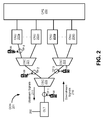
- Figure 2 shows an example of an ODN 201 with a point-to-multipoint configuration and including optical power splitters/combiners (OSCs) 220-222.
- the test instrument 100 may connect at different test points (e.g., TP1-4) in the ODN 201.
- the ODN 201 may include more than one OLT and may include more or less ONUs and OSCs than shown in figure 2 and may be connected in hierarchal configurations other than shown in figure 2 .
- the ODN 201 carries bidirectional optical traffic between the OLT 202 and ONUs 203a-n and 204a-n.
- Downstream signals 210 may be broadcasted by the OLT 202 to the ONUs 203a-n and 204a-n and may carry data intended for all the ONUs or individual ONUs.
- the downstream signals 210 are power divided by the OSCs 220-222. For example, each of the OSCs 220-222 power-divides the downstream signals 210 equally between its output legs.
- the OLT 202 may be connected to another network, e.g. an Ethernet network, which serves as an external source and recipient of communications.
- ONUs 203a-n and 204a-n may be connected to customer premises equipment 230 located at multiple customer premises and/or may be connected to other networks.
- the ONUs 203a-n and 204a-n may be connected to respective subscriber networks or subscriber devices, which may be a source of payload data transmitted in the ODN 201 from the subscriber/customer premises side.
- Upstream signals 211 from the ONUs 203a-n and 204a-n may be organized using TDMA.
- the OLT 202 operates as a "master", which assigns a time slot to each of the ONUs 203a-n and 204a-n, during which an upstream transmission may be performed.
- the OSCs 220-222 may combine all signals arriving at downstream facing ports into combined upstream signals, in which all of the upstream signal bursts from ONUs arrive properly separated in their time slots.
- test points TP1-4 are shown.
- the test instrument 100 may be connected at any of the test points, and may capture downstream signals at any of these test points to determine ONU identifiers of downstream ONUs. For example, at TP4, an ONU identifier may be determined for ONU 203a, and at TP3, ONU identifiers may be determined for ONUs 204a-n from downstream signals. Also, optical signals received by the test instrument 100 at any of the test points may be measured to determine power levels, loss, and other information.
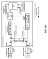
- FIG 3 shows the test instrument 100 according to an example.
- the test instrument 100 may include optical ports 1 and 2 connected to fiber optic cables in an ODN.
- the test instrument 100 is connected to the test point 105 shown in figure 1 , between OLT 102 and ONU 103.
- Optical ports 1 and 2 are connected to fiber optic cables in the ODN 101 at the test point 105.
- the test instrument 100 receives downstream signals 110 and upstream signals 111 via optical ports 1 and 2, respectively, and also passes through the signals (e.g., attenuated signals) towards their destination via an optical coupler 304, such as a 2x2 coupler.
- an optical coupler 304 such as a 2x2 coupler.
- the optical coupler 304 includes coupler port 331 and coupler port 332.
- the coupler port 331 is coupled to optical port 1, and coupler port 332 is coupled to optical port 2.
- the coupler ports 331 and 332 carry bidirectional optical traffic (e.g., downstream signals 110 and upstream signals 111) between optical ports 1 and 2.
- the optical coupler 304 further includes a drop port 341 for dropping a portion of the upstream signals 111 and a drop port 342 for dropping a portion of the downstream signals 110.
- the coupler 304 power splits the signals. For example, referring to downstream signals 110 received at optical port 1, the signals enter the coupler at coupler port 331 (shown as DS 100%). The coupler 304 power-splits the downstream signals 110. A major portion of the downstream signal power is output from the coupler port 332. For example, 80% of optical power of the downstream signals are passed to coupler port 332 (shown as DS 80%) and propagate to ONU 103 via optical port 2. A minor portion of the downstream signal power is output through the drop port 342. For example, twenty percent (20%) of the optical power of the downstream signals 110 (shown as DS 20%) are output through drop port 342 to downstream receiver 306.
- the 80/20 power split performed by the coupler 304 is an example, and the coupler 304 may be designed to perform other percentages of power split.
- the major portion of the signal power may be 3 to 4 times the minor portion.
- a similar operation may be performed for the upstream signals 111 to drop a portion of the upstream signals via drop port 341 to the upstream receiver 307.
- the downstream receiver 306 may include a filter 311 to pass desired wavelengths, a photodetector 312 to convert the dropped portion of the downstream optical signals 110 to electric signals, a power meter 313 to measure power levels and loss, a clock data recovery (CDR) circuit 314 to recover clock data from the electrical signal fed to the capture circuit 320, and other components to perform other functions.
- the power meter 313 may measure peak and/or an average optical power, and may include amplifiers connected to a peak/average signal detector. Many types of amplifiers may be used.
- the test instrument 100 may include a user interface 321 to receive user input and to display information, such as power levels, loss, ONU identifiers, etc.
- optical power level of the downstream traffic may be displayed together with the identification information of the ONU 103.
- the upstream receiver 307 may include similar components to the downstream receiver and other components as needed.
- the downstream and upstream receivers 306 and 307 may be referred to as optical receivers because they receive optical signals.
- the coupling of the test instrument 100 to the test point 105 causes the ONU 103 to be disconnected and re-connected to the ODN 101. This initiates an activation or discovery procedure between the OLT 102 and the ONU 103 upon re-coupling of the ONU 103 to the ODN via the test instrument 100.
- the activation procedure may correspond to a communication standard used in a particular network.
- the ONU 103 may transmit its ONU identifier (e.g., ONU serial number) to the OLT 102 for example to announce its presence, and the OLT 102 may respond by transmitting a message that includes the ONU identifier it received from the ONU 103 and other information.
- ONU identifier e.g., ONU serial number
- the test instrument 100 captures the ONU identifier in the message transmitted in the downstream signal from the OLT 102 to the ONU.
- the output of the downstream receiver 306 may include a digital data stream (e.g., bit stream) of bytes in the downstream signals 110.
- the capture circuit 320 captures the bytes of the downstream signals 110 during the activation procedure.
- the captured bytes include an identifier of the ONU 103.
- the capture circuit 320 extracts this information, thereby identifying the ONU 103, and stores this information in the data storage 351.
- the data storage 351 may store any information captured from the downstream signals 110 and upstream stream signals 111.
- the data storage 351 may store power level measurements or any other measurements taken by the test instrument 100.
- the stored information may be displayed and/or communicated via communications interface 322, such as WiFi, Ethernet, Bluetooth, USB, etc., to another device or system.
- the capture circuit 320 starts and stops saving the bytes of the downstream signals 110 to the data storage 351.
- the conditions of when to start and stop saving the bytes may be derived from data patterns found in the data stream and may also utilize other signals, e.g., provided from burst detector 352 and/or provided from processor 350.
- the burst detector 352 generates a signal when an upstream signal burst (e.g., upstream signals 111) arrives at the test instrument 100.
- the ONU 103 sends a message upstream to the OLT 102 during the activation period.
- the burst detector 352 detects the upstream signal and outputs a capture enable signal to the capture circuit 320, and the capture circuit 320 is enabled to capture and store the bytes of any subsequently received downstream signals 110 responsive to the capture enable signal. Accordingly, when the OLT 102 sends a response or acknowledgement to the received upstream message, the capture circuit 320 captures the information from the OLT message. If the capture enable signal is not set or is not output by the burst detector 352, the capture circuit 320 does not capture the bytes of the downstream signals 110.
- the capture enable signal minimizes opportunities to capture information for ONUs other than ONU 103 which may not be connected downstream of the test point 105.
- the test instrument 100 may operate without the burst detector 352 and the upstream receiver 307.
- the processor 350 controls the test process and performs data processing on the captured data.
- the processor 350 may also display information via the user interface 321 and transmit/receive data via the communications interface 322.
- the processor 350 may also send signals to the capture circuit 320 to control the capture circuit 320 to start and stop capturing data from the downstream signals 110.
- the processor 350 may enable the capture circuit 320 when it determines that the ONU 103 has entered the activation process.
- the hardware of the test instrument 100 may include a hardware processor, microcontroller, a digital signal processor (DSP), an application specific integrated circuit (ASIC), a field programmable gate array (FPGA) or other programmable logic device, discrete gate or transistor logic, discrete hardware components, or any combination thereof designed to perform the functions and methods described herein.
- DSP digital signal processor
- ASIC application specific integrated circuit
- FPGA field programmable gate array
- one or more of the functions and steps of the methods may be performed by the processor 350 or other hardware executing machine readable instructions stored in a non-transitory computer readable medium, such as the data storage 351, which may comprise RAM (random access memory), ROM (read only memory), EPROM (erasable, programmable ROM), EEPROM (electrically erasable, programmable ROM), hard drives, flash memory, or other types of storage devices, which may be volatile and/or nonvolatile.
- a non-transitory computer readable medium such as the data storage 351, which may comprise RAM (random access memory), ROM (read only memory), EPROM (erasable, programmable ROM), EEPROM (electrically erasable, programmable ROM), hard drives, flash memory, or other types of storage devices, which may be volatile and/or nonvolatile.
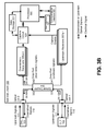
- Figure 3B shows an example of the test instrument 100 that is similar to as shown in figure 3A , except multiple downstream receivers 306a-n and multiple upstream receiver 307a-n are provided in the test instrument 100.
- Each of the downstream receivers 306a-n may include the components of the downstream receiver 306 shown in figure 3A
- each of the upstream receivers 307a-n may include the components of the upstream receiver 307 of figure 3A .
- FIG. 3B shows an example of the test instrument 100 whereby the test instrument 100 is capable of testing different PON systems.
- Different PON systems generally use different wavelengths for downstream and upstream signals and may have different data rates.
- Each of the downstream receivers 306a-n and upstream receivers 307a-n is used for a particular PON system.
- the filters in each of the downstream receivers 306a-n and upstream receivers 307a-n pass the wavelengths of the corresponding PON system, so the optical signals for a particular PON system are received, measured and converted to electrical signals by its corresponding receiver.
- the downstream receivers 306a-n and upstream receivers 307a-n may be coupled to the same capture circuit 320 or may be coupled to separate capture circuits to capture information from the downstream signals 110, including the identifiers of the ONUs in the particular PON system that are downstream from the test point.
- the downstream signals 110 for example include signals for different PON systems.
- Each pair of receivers may be for a different PON system.
- receivers 306a and 307a are for receiving G-PON signals
- receivers 306b and 307b are for receiving XG-PON, etc.
- the capture circuit 320 (or multiple capture circuits if a capture circuit is provided for each PON system) captures ONU identifiers and other information for each PON system and stores it in the data storage 351. Any suitable number of downstream and upstream receivers may be provided in the test instrument 100, and may be based on the number of different PON systems that may be implemented on an ODN.
- Figure 4 shows a method 400 that may be performed by the test instrument 100. Steps of the method 400 and other methods described herein may be performed in orders other than shown and described or at the same time.
- the method 400 is described by way of example with respect to figure 3 .
- the test instrument 100 is connected at test point 105 in ODN 101.
- the ONU 103 enters into an activation process according to a communications standard, an example of which is described with respect to figures 5 and 6 .
- the activation process may be initiated in response to connecting the ONU 103.
- connecting the test instrument 100 to the test point 105 causes the ONU 103 to be disconnected and re-connected to the ODN 101, initiating the activation process.
- the burst detector 352 is reset for example by the processor 350.
- the burst detector 352 may not send a capture enable signal to the capture circuit 320 or the capture enable signal is set to a value indicating that the capture circuit 320 is not enabled to capture information from downstream signals.
- the processor 350 may reset the burst detector 352 for example when the processor determines the test instrument 100 is initially connected to the test point 105 and prior to receiving an upstream signal from the ONU 103.
- the processor 350 may send a signal to the burst detector 352 to reset.
- the test instrument 100 may not include a burst detector 352 and in that case any steps involving the burst detector 352 are not performed.
- the test instrument 100 synchronizes with received downstream signals 110 in order to receive data sent from the OLT 102.
- the burst detector 352 detects a first upstream burst after the test instrument 100 is connected to the test point 105, and sends capture enable signal to the capture circuit 320.
- the first upstream burst which may include a message sent upstream from the ONU 103 to the OLT 102 during an activation procedure, indicates that the ONU 103 has currently started its activation process.
- the capture circuit 320 is enabled to capture data from downstream signals 110 from the OLT 102.
- the capture circuit 320 captures the ONU identifier sent in the downstream signals 110 from the OLT 102 after being enabled. For example, the capture circuit 320 receives a digital data stream from the downstream receiver 306, identifies an OLT message including an identifier of the ONU from the digital data stream, and stores bytes of the OLT message, including the identifier of the ONU, in the data storage 351.
- An OLT message may include a header and payload, and is transmitted from the OLT 102 downstream in the ODN 101 to one or more ONUs.
- the capture circuit 320 is to start and stop storing data based on conditions derived from at least one of data patterns found in the digital data stream which may identify a message containing the ONU identifier, the burst detector 352 detecting an upstream signal transmitted from the ONU, and signals from the processor 350.
- the optical signals received at the test instrument 100 may be measured and stored.
- power levels of the downstream signals 110 are measured by the power meter 313 and stored in the data storage 351 and may be displayed via the user interface 321.
- the test instrument 100 can test for multiple ON Us at a single test point. For example, referring to figure 2 , the test instrument 100 is connected at TP 2.
- the method 400 is performed to determine the ONU identifiers for ONUs 203a-n downstream from TP2 from downstream signals 110 sent from the OLT 202.
- the capture circuit 320 may stop capturing information from messages from the OLT after a predefined number of messages are captured, after a predefined time interval, and/or after some other messages are received that may indicate the activation process is completed.
- the ONU identifier may be extracted from downstream messages from the OLT during an activation procedure of the ONU.
- An ONU may communicate with the OLT according to a communication standard which sets forth the message exchange between the OLT and ONU during the activation procedure.
- the communication standard may include the ITU-T G.984.3 communication standard for a gigabit-capable passive optical network (G-PON): Transmission convergence layer specification.
- the message exchange between the OLT and OLU during the activation procedure according to the G.984.3 communication standard includes the exchange of physical layer operation and maintenance (PLOAM) messages.
- PLOAM physical layer operation and maintenance
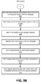
- Figures 5A-B show a method describing the G-PON activation procedure in conjunction with steps of the method 400 performed by the test instrument 100 to determine ONU identifiers from downstream signals 110.
- the method 500 is described by way of example with respect to the test instrument 100 shown in figures 1 and 3 .
- Upstream and downstream messages sent between the ONU 103 and the OLT 102 pass through the test instrument 100 after the test instrument 100 is connected at the test point 105.
- the test instrument 100 can measure power levels and other signal parameters of the upstream signals 111 and downstream signals 110 passing through the test instrument 100.
- the method 500 does not include steps performed by the burst detector 352, but the method 500 may include those steps as described in the method 400.
- the activation procedure is initiated in the ONU 103, for example, in response to the ONU 103 being re-connected to the ODN 101 when the test instrument 100 is connected at test point 105.
- the ONU 103 waits for a broadcast from the OLT
- the ONU 103 receives an Upstream_Overhead PLOAM message, optionally followed by an Extended_Burst_Length PLOAM message periodically issued by the OLT 102, and determines PON operating parameters (e.g., the lengths and patterns of the burst mode overhead components, value of the pre-assigned delay, and initial optical power level) from the received PLOAM messages.
- PON operating parameters e.g., the lengths and patterns of the burst mode overhead components, value of the pre-assigned delay, and initial optical power level
- the ONU 103 sends an upstream message to the OLT 102 including its serial number (e.g., Serial_Number_ONU message) in response to a broadcast serial number request message received from the OLT 102.
- serial number e.g., Serial_Number_ONU message
- the ONU 103 adjusts its transmission optical power level using the absence of directed messages from the OLT as a negative acknowledgment.
- the OLT 102 receives the Serial_Number_ONU message and extracts the serial number of the ONU 103 and assigns an ONU-ID to it and sends an Assign_ONU-ID message to the ONU 103, including the serial number of the ONU and the ONU-ID assigned by the OLT 102.
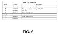
- Bytes of the Assign_ONU-ID message are shown in figure 6 .
- Byte 2 includes a pattern of bits that indicates that the message is an Assign_ONU-ID message.
- Byte 3 includes the ONU-ID and bytes 4-11 include the serial number of the ONU 103.
- the test instrument 100 receives a downstream signal from the OLT 102 including the Assign_ONU-ID message on optical port 1.
- the test instrument sends a major portion of the downstream signal to the ONU 103 via optical coupler 304 and optical port 2. The major portion for example is shown in figure 3 as DS 80%.
- a minor portion of the downstream signal is dropped via drop port 342 and sent to the downstream receiver 306.
- the capture circuit 320 captures the data in the Assign_ONU-ID message, including the ONU-ID and the ONU serial number in bytes 3-11 of the message. The data is stored in the data storage 351.
- Determining when to start and stop capturing data from the downstream signal may be based on conditions derived from at least one of data patterns found in the digital data stream (e.g., data patterns identifying the Assign_ONU-ID message), signals from the burst detector 352, and signals from the processor 350.
- data patterns found in the digital data stream e.g., data patterns identifying the Assign_ONU-ID message
- signals from the burst detector 352 e.g., data patterns identifying the Assign_ONU-ID message
- signals from the burst detector 352 e.g., data patterns identifying the Assign_ONU-ID message
- the OLT 102 assigns delay time for each ONU connected to the OLT 102 via the ODN 101 so different propagation delays are equalized.
- the ONU 103 adjusts the start of its upstream frame clock based on its assigned equalization delay, and the ONU 103 completes activation and starts regular operation.
- the ONU 103 may go through various states. In an initial state, the ONU 103 is powered up, and in a standby state, the ONU 103 is waiting for the PON parameters from the OLT 102. In a serial number state, the ONU 103 makes itself known to the OLT 102 by sending its serial number to the OLT 102 and the ONU 103 receives the Assign_ONU-ID message with the ONU identifiers. In a ranging state, the ONU 103 synchronizes its upstream frame clock based on its assigned equalization delay. The ONU identifiers, such as the ONU-ID and the ONU serial number, may be captured from the downstream signals 110 from the OLT 102 in the serial number state.
- ONU identifiers may be captured from downstream signals transmitted from an OLT when communications standards other than the GPON communications standards are implemented in the PON. ONU identifiers may be captured from downstream signals for any communications standard that includes transmission of downstream messages that include ONU identifiers.
Landscapes
- Physics & Mathematics (AREA)
- Engineering & Computer Science (AREA)
- Computer Networks & Wireless Communication (AREA)
- Electromagnetism (AREA)
- Signal Processing (AREA)
- Optics & Photonics (AREA)
- Chemical & Material Sciences (AREA)
- Analytical Chemistry (AREA)
- General Physics & Mathematics (AREA)
- Optical Communication System (AREA)
- Small-Scale Networks (AREA)
Applications Claiming Priority (1)
| Application Number | Priority Date | Filing Date | Title |
|---|---|---|---|
| US14/788,116 US9673897B2 (en) | 2015-06-30 | 2015-06-30 | Optical network test instrument including optical network unit identifier capture capability from downstream signals |
Publications (2)
| Publication Number | Publication Date |
|---|---|
| EP3112838A1 true EP3112838A1 (fr) | 2017-01-04 |
| EP3112838B1 EP3112838B1 (fr) | 2022-08-10 |
Family
ID=56737870
Family Applications (1)
| Application Number | Title | Priority Date | Filing Date |
|---|---|---|---|
| EP16176809.8A Active EP3112838B1 (fr) | 2015-06-30 | 2016-06-29 | Instrument de test de réseau optique comprenant une capacité de capture d'identificateur d'unité de réseau optique à partir de signaux en aval |
Country Status (2)
| Country | Link |
|---|---|
| US (2) | US9673897B2 (fr) |
| EP (1) | EP3112838B1 (fr) |
Cited By (3)
| Publication number | Priority date | Publication date | Assignee | Title |
|---|---|---|---|---|
| CN110196153A (zh) * | 2019-05-22 | 2019-09-03 | 上海嘉慧光电子技术有限公司 | 一种基于双联lc的可拆卸探测结构件 |
| CN110213678A (zh) * | 2018-02-28 | 2019-09-06 | 上海诺基亚贝尔股份有限公司 | 无源光网络中的通信方法、设备和计算机可读介质 |
| EP4373011A1 (fr) * | 2022-11-18 | 2024-05-22 | Viavi Solutions Inc. | Instrument de test de réseau optique comprenant un test pour une unité de réseau optique et une attribution de terminal de ligne optique |
Families Citing this family (22)
| Publication number | Priority date | Publication date | Assignee | Title |
|---|---|---|---|---|
| JP6547512B2 (ja) * | 2015-08-10 | 2019-07-24 | 富士通株式会社 | 伝送装置及び光透過特性の測定方法 |
| US10644748B2 (en) | 2015-08-26 | 2020-05-05 | Viavi Solutions Inc. | Network test instrument with cable connection and signature testing |
| US10615894B2 (en) * | 2015-08-31 | 2020-04-07 | Viavi Solutions Inc. | Network test instrument with testing session analysis |
| CN106549706B (zh) * | 2015-09-16 | 2019-04-26 | 青岛海信宽带多媒体技术有限公司 | 一种电口模块 |
| EP3382919A4 (fr) * | 2017-01-24 | 2019-01-16 | Huawei Technologies Co., Ltd. | Procédé de communication, dispositif et système pour réseau optique passif (pon) |
| US10128943B2 (en) * | 2017-04-06 | 2018-11-13 | At&T Intellectual Property I, L.P. | Predictive maintenance of optical transport network system |
| WO2020062938A1 (fr) * | 2018-09-24 | 2020-04-02 | Huawei Technologies Co., Ltd. | Activation d'unité de réseau optique (onu) à débits multiples |
| TWI742598B (zh) * | 2020-04-06 | 2021-10-11 | 中華電信股份有限公司 | 行動化查測被動式光網路之系統與方法 |
| US11115124B1 (en) * | 2020-05-29 | 2021-09-07 | Corning Research & Development Corporation | Adaptive scheduling for periodic data traffic in an optical communications network for a wireless communications system (WCS) |
| CN111901706B (zh) * | 2020-06-17 | 2022-05-06 | 烽火通信科技股份有限公司 | 一种tdm pon中的onu发现测距方法和系统 |
| JP7424506B2 (ja) * | 2020-10-14 | 2024-01-30 | 日本電信電話株式会社 | モニタ装置及び光ファイバ特定方法 |
| US11601196B2 (en) | 2021-04-27 | 2023-03-07 | Dell Products L.P. | Real-time health monitoring in an all-photonics network |
| US11677463B2 (en) | 2021-04-27 | 2023-06-13 | Dell Products L.P. | Infrastructure integrity and attestation of an all-photonics network |
| US11595123B2 (en) | 2021-04-27 | 2023-02-28 | Dell Products L.P. | Identifying optimal paths in an all-photonics network |
| US11388493B1 (en) | 2021-04-27 | 2022-07-12 | Dell Products L.P. | Secure and attested all-photonics network |
| US11595122B2 (en) | 2021-04-27 | 2023-02-28 | Dell Products L.P. | Identifying link fingerprint anomalies in real-time in an all-photonics network |
| US11595124B2 (en) | 2021-04-27 | 2023-02-28 | Dell Products L.P. | Path management for tiered service level agreements in an all-photonics network |
| CN116131934A (zh) * | 2021-11-15 | 2023-05-16 | 深圳市滕源科技有限公司 | Onu的自动检测系统 |
| US12531637B2 (en) * | 2022-10-17 | 2026-01-20 | Boost SubscriberCo L.L.C. | Network probing including split light signal monitoring |
| US11936424B1 (en) * | 2023-04-27 | 2024-03-19 | Frontier Communications Holdings, Llc | Passive optical network adaptor with wireless interface |
| US11997437B1 (en) * | 2023-04-27 | 2024-05-28 | Frontier Communications Holdings, Llc | In-line diagnostic tool in passive optical networks |
| CN120498995B (zh) * | 2023-10-10 | 2026-03-13 | 华为技术有限公司 | 一种上行开销配置方法、光纤网络系统以及相关设备 |
Citations (3)
| Publication number | Priority date | Publication date | Assignee | Title |
|---|---|---|---|---|
| EP2690802A1 (fr) * | 2011-03-23 | 2014-01-29 | Telnet Redes Inteligentes, S.A. | Système pour la certification d'un réseau optique passif et pour la détection de problèmes et d'avaries dans les derniers segments de fibre |
| CN102752211B (zh) * | 2012-07-11 | 2014-12-03 | 烽火通信科技股份有限公司 | 自动捕获10g epon报文的定时装置及方法 |
| EP2846479A1 (fr) * | 2013-08-07 | 2015-03-11 | JDSU Deutschland GmbH | Test d'un réseau optique passif |
Family Cites Families (25)
| Publication number | Priority date | Publication date | Assignee | Title |
|---|---|---|---|---|
| US7688843B2 (en) * | 2002-09-13 | 2010-03-30 | Pmc-Sierra Israel Ltd. | Operations method in an ethernet passive optical network that includes a network unit with multiple entities |
| US9312953B2 (en) * | 2003-03-03 | 2016-04-12 | Alexander Ivan Soto | System and method for performing in-service optical network certification |
| US7187861B2 (en) | 2003-10-15 | 2007-03-06 | Exfo Electro-Optical Engineering Inc. | Method and apparatus for testing optical networks |
| US20060007426A1 (en) * | 2004-07-08 | 2006-01-12 | Weller Whitney T | Novel Algorithm, Method and apparatus for In-Service Testing of Passive Optical Networks (PON) and Fiber to the Premise (FTTP) Networks |
| EP1856825A2 (fr) | 2005-03-07 | 2007-11-21 | Nettest North America, Inc. | Dispositif de mesure de pertes dans des reseaux optiques passifs et procede d'utilisation |
| JP2007096847A (ja) * | 2005-09-29 | 2007-04-12 | Fujitsu Ltd | 光アクセス・ネットワーク試験装置 |
| US20070242954A1 (en) | 2006-04-14 | 2007-10-18 | Tellabs Petaluma, Inc. | System and method for monitoring transmissions within a passive optical network |
| JP4910735B2 (ja) | 2007-02-05 | 2012-04-04 | 富士通株式会社 | ネットワーク試験装置、ネットワーク試験方法およびネットワーク試験プログラム |
| EP1965517A1 (fr) | 2007-02-28 | 2008-09-03 | British Telecommunications Public Limited Company | Test d'un réseau optique |
| US7684702B2 (en) * | 2007-05-21 | 2010-03-23 | Inventec Multimedia & Telecom Corporation | Optical link monitoring system and method for passive optical network |
| ES2656788T3 (es) | 2008-05-09 | 2018-02-28 | Afl Telecommunications Llc | Reflectómetro óptico en el dominio del tiempo |
| CN101630979B (zh) * | 2008-07-16 | 2015-05-06 | 华为技术有限公司 | 一种延长器、数据传输方法及无源光网络系统 |
| US8213002B2 (en) | 2009-03-04 | 2012-07-03 | Fluke Corporation | PON tester |
| TWI406526B (zh) | 2009-06-12 | 2013-08-21 | Univ Nat Taiwan Science Tech | 用於光網路監控及錯誤檢測之光信號切換模組 |
| TWI466466B (zh) | 2009-06-12 | 2014-12-21 | Univ Nat Taiwan Science Tech | 具雙向性之多波長路由與放大模組 |
| CN101998183B (zh) * | 2009-08-10 | 2015-05-13 | 中兴通讯股份有限公司 | 一种无源光网络中ploam消息的传输方法及组装方法 |
| EP2337247A1 (fr) * | 2009-12-21 | 2011-06-22 | Nokia Siemens Networks Oy | Procédé et appareil pour empêcher l'interférence de signal dans un réseau optique passif |
| CN103125085B (zh) * | 2010-12-27 | 2016-04-27 | 三菱电机株式会社 | 中继装置、站侧光通信装置、通信系统以及带宽分配方法 |
| US20120288273A1 (en) * | 2011-05-12 | 2012-11-15 | Alcatel-Lucent Usa, Inc. | Intelligent splitter monitor |
| WO2013098325A1 (fr) * | 2011-12-30 | 2013-07-04 | Nokia Siemens Networks Oy | Méthode et agencement de transmission de signal et de compensation de rétroréflections dans des systèmes pon à accès optique |
| US8805183B2 (en) | 2012-02-08 | 2014-08-12 | Broadcom Corporation | Optical line terminal (OLT) and method therefore for performing in-band and out-band OTDR measurements |
| US8948589B2 (en) * | 2012-03-30 | 2015-02-03 | Alcatel Lucent | Apparatus and method for testing fibers in a PON |
| EP2675089B1 (fr) * | 2012-06-15 | 2019-07-24 | ADVA Optical Networking SE | Procédé de fonctionnement d'un premier noed optique et second noed optique |
| US9571156B2 (en) * | 2013-03-14 | 2017-02-14 | Cisco Technology, Inc. | Burst triggered signal analysis |
| US10003428B2 (en) * | 2013-05-15 | 2018-06-19 | Zte Corporation | Using noisy window for uncalibrated optical network unit activation |
-
2015
- 2015-06-30 US US14/788,116 patent/US9673897B2/en active Active
-
2016
- 2016-06-29 EP EP16176809.8A patent/EP3112838B1/fr active Active
-
2017
- 2017-05-04 US US15/587,238 patent/US10742317B2/en active Active
Patent Citations (3)
| Publication number | Priority date | Publication date | Assignee | Title |
|---|---|---|---|---|
| EP2690802A1 (fr) * | 2011-03-23 | 2014-01-29 | Telnet Redes Inteligentes, S.A. | Système pour la certification d'un réseau optique passif et pour la détection de problèmes et d'avaries dans les derniers segments de fibre |
| CN102752211B (zh) * | 2012-07-11 | 2014-12-03 | 烽火通信科技股份有限公司 | 自动捕获10g epon报文的定时装置及方法 |
| EP2846479A1 (fr) * | 2013-08-07 | 2015-03-11 | JDSU Deutschland GmbH | Test d'un réseau optique passif |
Cited By (4)
| Publication number | Priority date | Publication date | Assignee | Title |
|---|---|---|---|---|
| CN110213678A (zh) * | 2018-02-28 | 2019-09-06 | 上海诺基亚贝尔股份有限公司 | 无源光网络中的通信方法、设备和计算机可读介质 |
| CN110213678B (zh) * | 2018-02-28 | 2020-09-08 | 上海诺基亚贝尔股份有限公司 | 无源光网络中的通信方法、设备和计算机可读介质 |
| CN110196153A (zh) * | 2019-05-22 | 2019-09-03 | 上海嘉慧光电子技术有限公司 | 一种基于双联lc的可拆卸探测结构件 |
| EP4373011A1 (fr) * | 2022-11-18 | 2024-05-22 | Viavi Solutions Inc. | Instrument de test de réseau optique comprenant un test pour une unité de réseau optique et une attribution de terminal de ligne optique |
Also Published As
| Publication number | Publication date |
|---|---|
| US9673897B2 (en) | 2017-06-06 |
| US20170338888A1 (en) | 2017-11-23 |
| EP3112838B1 (fr) | 2022-08-10 |
| US20170005723A1 (en) | 2017-01-05 |
| US10742317B2 (en) | 2020-08-11 |
Similar Documents
| Publication | Publication Date | Title |
|---|---|---|
| EP3112838B1 (fr) | Instrument de test de réseau optique comprenant une capacité de capture d'identificateur d'unité de réseau optique à partir de signaux en aval | |
| US9379813B2 (en) | Testing a passive optical network | |
| KR100584383B1 (ko) | 광선로가입자장치들의 링크 상태를 관리하기 위한광선로종단장치 및 이를 적용한 기가비트 이더넷 기반의수동 광가입자망 | |
| US9319139B2 (en) | Long distance multi-mode communication | |
| CN101677415B (zh) | 光网络系统数据链路切换方法、光网络单元及系统 | |
| US8774623B2 (en) | Passive optical network system and method for detecting fault in optical network terminal | |
| US20150037035A1 (en) | Network system | |
| US20080056714A1 (en) | Method and Apparatus for Obtaining an Optical Power Level in a Pon Network | |
| US20120027402A1 (en) | In-Band Optical Frequency Division Reflectometry | |
| CN105451840A (zh) | 一种光时域反射仪实现装置及系统 | |
| EP3975580B1 (fr) | Procédé de détermination de connexion de terminaux de réseau optique, appareil et système | |
| CN101369846A (zh) | 一种无源光网络信号监控方法及电中继再生器 | |
| KR100738559B1 (ko) | Epon 시스템의 대역폭 설정 방법 및 그 장치 | |
| JP2008277893A (ja) | マルチレートponシステムとその局側装置、端末装置及び伝送レート設定方法 | |
| JP4891715B2 (ja) | 受動型光ネットワークシステム | |
| EP4373011A1 (fr) | Instrument de test de réseau optique comprenant un test pour une unité de réseau optique et une attribution de terminal de ligne optique | |
| JP2015008456A (ja) | 光通信判別装置、光通信判別方法および端末局の敷設方法 | |
| WO2017179241A1 (fr) | Appareil de relais de signaux optiques et procédé de relais | |
| JP5949228B2 (ja) | 通信監視装置および通信監視方法 | |
| JP2012173184A (ja) | 光多重反射点特定装置及び方法 | |
| JP5411805B2 (ja) | 受動光網システム及び送信光制御方法、光多重終端装置及び光網終端装置 | |
| Premadi et al. | Optical Managing Project--Effectively Survivability and Monitoring System | |
| KR102211854B1 (ko) | Pon 기반 광통신장치 및 이를 포함하는 epon 시스템 | |
| CN106160862A (zh) | 一种光纤网络接入系统及其组网方法 | |
| JP2012151760A (ja) | モニタ装置および試験方法 |
Legal Events
| Date | Code | Title | Description |
|---|---|---|---|
| PUAI | Public reference made under article 153(3) epc to a published international application that has entered the european phase |
Free format text: ORIGINAL CODE: 0009012 |
|
| STAA | Information on the status of an ep patent application or granted ep patent |
Free format text: STATUS: THE APPLICATION HAS BEEN PUBLISHED |
|
| AK | Designated contracting states |
Kind code of ref document: A1 Designated state(s): AL AT BE BG CH CY CZ DE DK EE ES FI FR GB GR HR HU IE IS IT LI LT LU LV MC MK MT NL NO PL PT RO RS SE SI SK SM TR |
|
| AX | Request for extension of the european patent |
Extension state: BA ME |
|
| STAA | Information on the status of an ep patent application or granted ep patent |
Free format text: STATUS: REQUEST FOR EXAMINATION WAS MADE |
|
| 17P | Request for examination filed |
Effective date: 20170703 |
|
| RBV | Designated contracting states (corrected) |
Designated state(s): AL AT BE BG CH CY CZ DE DK EE ES FI FR GB GR HR HU IE IS IT LI LT LU LV MC MK MT NL NO PL PT RO RS SE SI SK SM TR |
|
| STAA | Information on the status of an ep patent application or granted ep patent |
Free format text: STATUS: EXAMINATION IS IN PROGRESS |
|
| 17Q | First examination report despatched |
Effective date: 20191129 |
|
| GRAP | Despatch of communication of intention to grant a patent |
Free format text: ORIGINAL CODE: EPIDOSNIGR1 |
|
| STAA | Information on the status of an ep patent application or granted ep patent |
Free format text: STATUS: GRANT OF PATENT IS INTENDED |
|
| INTG | Intention to grant announced |
Effective date: 20220218 |
|
| GRAS | Grant fee paid |
Free format text: ORIGINAL CODE: EPIDOSNIGR3 |
|
| GRAA | (expected) grant |
Free format text: ORIGINAL CODE: 0009210 |
|
| STAA | Information on the status of an ep patent application or granted ep patent |
Free format text: STATUS: THE PATENT HAS BEEN GRANTED |
|
| AK | Designated contracting states |
Kind code of ref document: B1 Designated state(s): AL AT BE BG CH CY CZ DE DK EE ES FI FR GB GR HR HU IE IS IT LI LT LU LV MC MK MT NL NO PL PT RO RS SE SI SK SM TR |
|
| REG | Reference to a national code |
Ref country code: AT Ref legal event code: REF Ref document number: 1510900 Country of ref document: AT Kind code of ref document: T Effective date: 20220815 Ref country code: CH Ref legal event code: EP |
|
| REG | Reference to a national code |
Ref country code: IE Ref legal event code: FG4D |
|
| REG | Reference to a national code |
Ref country code: DE Ref legal event code: R096 Ref document number: 602016074107 Country of ref document: DE |
|
| REG | Reference to a national code |
Ref country code: NL Ref legal event code: MP Effective date: 20220810 |
|
| REG | Reference to a national code |
Ref country code: LT Ref legal event code: MG9D |
|
| PG25 | Lapsed in a contracting state [announced via postgrant information from national office to epo] |
Ref country code: SE Free format text: LAPSE BECAUSE OF FAILURE TO SUBMIT A TRANSLATION OF THE DESCRIPTION OR TO PAY THE FEE WITHIN THE PRESCRIBED TIME-LIMIT Effective date: 20220810 Ref country code: RS Free format text: LAPSE BECAUSE OF FAILURE TO SUBMIT A TRANSLATION OF THE DESCRIPTION OR TO PAY THE FEE WITHIN THE PRESCRIBED TIME-LIMIT Effective date: 20220810 Ref country code: PT Free format text: LAPSE BECAUSE OF FAILURE TO SUBMIT A TRANSLATION OF THE DESCRIPTION OR TO PAY THE FEE WITHIN THE PRESCRIBED TIME-LIMIT Effective date: 20221212 Ref country code: NO Free format text: LAPSE BECAUSE OF FAILURE TO SUBMIT A TRANSLATION OF THE DESCRIPTION OR TO PAY THE FEE WITHIN THE PRESCRIBED TIME-LIMIT Effective date: 20221110 Ref country code: NL Free format text: LAPSE BECAUSE OF FAILURE TO SUBMIT A TRANSLATION OF THE DESCRIPTION OR TO PAY THE FEE WITHIN THE PRESCRIBED TIME-LIMIT Effective date: 20220810 Ref country code: LV Free format text: LAPSE BECAUSE OF FAILURE TO SUBMIT A TRANSLATION OF THE DESCRIPTION OR TO PAY THE FEE WITHIN THE PRESCRIBED TIME-LIMIT Effective date: 20220810 Ref country code: LT Free format text: LAPSE BECAUSE OF FAILURE TO SUBMIT A TRANSLATION OF THE DESCRIPTION OR TO PAY THE FEE WITHIN THE PRESCRIBED TIME-LIMIT Effective date: 20220810 Ref country code: FI Free format text: LAPSE BECAUSE OF FAILURE TO SUBMIT A TRANSLATION OF THE DESCRIPTION OR TO PAY THE FEE WITHIN THE PRESCRIBED TIME-LIMIT Effective date: 20220810 Ref country code: ES Free format text: LAPSE BECAUSE OF FAILURE TO SUBMIT A TRANSLATION OF THE DESCRIPTION OR TO PAY THE FEE WITHIN THE PRESCRIBED TIME-LIMIT Effective date: 20220810 |
|
| REG | Reference to a national code |
Ref country code: AT Ref legal event code: MK05 Ref document number: 1510900 Country of ref document: AT Kind code of ref document: T Effective date: 20220810 |
|
| PG25 | Lapsed in a contracting state [announced via postgrant information from national office to epo] |
Ref country code: PL Free format text: LAPSE BECAUSE OF FAILURE TO SUBMIT A TRANSLATION OF THE DESCRIPTION OR TO PAY THE FEE WITHIN THE PRESCRIBED TIME-LIMIT Effective date: 20220810 Ref country code: IS Free format text: LAPSE BECAUSE OF FAILURE TO SUBMIT A TRANSLATION OF THE DESCRIPTION OR TO PAY THE FEE WITHIN THE PRESCRIBED TIME-LIMIT Effective date: 20221210 Ref country code: HR Free format text: LAPSE BECAUSE OF FAILURE TO SUBMIT A TRANSLATION OF THE DESCRIPTION OR TO PAY THE FEE WITHIN THE PRESCRIBED TIME-LIMIT Effective date: 20220810 Ref country code: GR Free format text: LAPSE BECAUSE OF FAILURE TO SUBMIT A TRANSLATION OF THE DESCRIPTION OR TO PAY THE FEE WITHIN THE PRESCRIBED TIME-LIMIT Effective date: 20221111 |
|
| PG25 | Lapsed in a contracting state [announced via postgrant information from national office to epo] |
Ref country code: SM Free format text: LAPSE BECAUSE OF FAILURE TO SUBMIT A TRANSLATION OF THE DESCRIPTION OR TO PAY THE FEE WITHIN THE PRESCRIBED TIME-LIMIT Effective date: 20220810 Ref country code: RO Free format text: LAPSE BECAUSE OF FAILURE TO SUBMIT A TRANSLATION OF THE DESCRIPTION OR TO PAY THE FEE WITHIN THE PRESCRIBED TIME-LIMIT Effective date: 20220810 Ref country code: DK Free format text: LAPSE BECAUSE OF FAILURE TO SUBMIT A TRANSLATION OF THE DESCRIPTION OR TO PAY THE FEE WITHIN THE PRESCRIBED TIME-LIMIT Effective date: 20220810 Ref country code: CZ Free format text: LAPSE BECAUSE OF FAILURE TO SUBMIT A TRANSLATION OF THE DESCRIPTION OR TO PAY THE FEE WITHIN THE PRESCRIBED TIME-LIMIT Effective date: 20220810 Ref country code: AT Free format text: LAPSE BECAUSE OF FAILURE TO SUBMIT A TRANSLATION OF THE DESCRIPTION OR TO PAY THE FEE WITHIN THE PRESCRIBED TIME-LIMIT Effective date: 20220810 |
|
| REG | Reference to a national code |
Ref country code: DE Ref legal event code: R097 Ref document number: 602016074107 Country of ref document: DE |
|
| PG25 | Lapsed in a contracting state [announced via postgrant information from national office to epo] |
Ref country code: SK Free format text: LAPSE BECAUSE OF FAILURE TO SUBMIT A TRANSLATION OF THE DESCRIPTION OR TO PAY THE FEE WITHIN THE PRESCRIBED TIME-LIMIT Effective date: 20220810 Ref country code: EE Free format text: LAPSE BECAUSE OF FAILURE TO SUBMIT A TRANSLATION OF THE DESCRIPTION OR TO PAY THE FEE WITHIN THE PRESCRIBED TIME-LIMIT Effective date: 20220810 |
|
| PLBE | No opposition filed within time limit |
Free format text: ORIGINAL CODE: 0009261 |
|
| STAA | Information on the status of an ep patent application or granted ep patent |
Free format text: STATUS: NO OPPOSITION FILED WITHIN TIME LIMIT |
|
| PG25 | Lapsed in a contracting state [announced via postgrant information from national office to epo] |
Ref country code: AL Free format text: LAPSE BECAUSE OF FAILURE TO SUBMIT A TRANSLATION OF THE DESCRIPTION OR TO PAY THE FEE WITHIN THE PRESCRIBED TIME-LIMIT Effective date: 20220810 |
|
| 26N | No opposition filed |
Effective date: 20230511 |
|
| PG25 | Lapsed in a contracting state [announced via postgrant information from national office to epo] |
Ref country code: SI Free format text: LAPSE BECAUSE OF FAILURE TO SUBMIT A TRANSLATION OF THE DESCRIPTION OR TO PAY THE FEE WITHIN THE PRESCRIBED TIME-LIMIT Effective date: 20220810 |
|
| PG25 | Lapsed in a contracting state [announced via postgrant information from national office to epo] |
Ref country code: MC Free format text: LAPSE BECAUSE OF FAILURE TO SUBMIT A TRANSLATION OF THE DESCRIPTION OR TO PAY THE FEE WITHIN THE PRESCRIBED TIME-LIMIT Effective date: 20220810 |
|
| PG25 | Lapsed in a contracting state [announced via postgrant information from national office to epo] |
Ref country code: MC Free format text: LAPSE BECAUSE OF FAILURE TO SUBMIT A TRANSLATION OF THE DESCRIPTION OR TO PAY THE FEE WITHIN THE PRESCRIBED TIME-LIMIT Effective date: 20220810 |
|
| REG | Reference to a national code |
Ref country code: CH Ref legal event code: PL |
|
| REG | Reference to a national code |
Ref country code: BE Ref legal event code: MM Effective date: 20230630 |
|
| PG25 | Lapsed in a contracting state [announced via postgrant information from national office to epo] |
Ref country code: LU Free format text: LAPSE BECAUSE OF NON-PAYMENT OF DUE FEES Effective date: 20230629 |
|
| REG | Reference to a national code |
Ref country code: IE Ref legal event code: MM4A |
|
| PG25 | Lapsed in a contracting state [announced via postgrant information from national office to epo] |
Ref country code: LU Free format text: LAPSE BECAUSE OF NON-PAYMENT OF DUE FEES Effective date: 20230629 |
|
| PG25 | Lapsed in a contracting state [announced via postgrant information from national office to epo] |
Ref country code: IE Free format text: LAPSE BECAUSE OF NON-PAYMENT OF DUE FEES Effective date: 20230629 |
|
| PG25 | Lapsed in a contracting state [announced via postgrant information from national office to epo] |
Ref country code: IE Free format text: LAPSE BECAUSE OF NON-PAYMENT OF DUE FEES Effective date: 20230629 Ref country code: CH Free format text: LAPSE BECAUSE OF NON-PAYMENT OF DUE FEES Effective date: 20230630 |
|
| PG25 | Lapsed in a contracting state [announced via postgrant information from national office to epo] |
Ref country code: IT Free format text: LAPSE BECAUSE OF FAILURE TO SUBMIT A TRANSLATION OF THE DESCRIPTION OR TO PAY THE FEE WITHIN THE PRESCRIBED TIME-LIMIT Effective date: 20220810 Ref country code: BE Free format text: LAPSE BECAUSE OF NON-PAYMENT OF DUE FEES Effective date: 20230630 |
|
| PG25 | Lapsed in a contracting state [announced via postgrant information from national office to epo] |
Ref country code: BG Free format text: LAPSE BECAUSE OF FAILURE TO SUBMIT A TRANSLATION OF THE DESCRIPTION OR TO PAY THE FEE WITHIN THE PRESCRIBED TIME-LIMIT Effective date: 20220810 |
|
| PG25 | Lapsed in a contracting state [announced via postgrant information from national office to epo] |
Ref country code: BG Free format text: LAPSE BECAUSE OF FAILURE TO SUBMIT A TRANSLATION OF THE DESCRIPTION OR TO PAY THE FEE WITHIN THE PRESCRIBED TIME-LIMIT Effective date: 20220810 |
|
| PGFP | Annual fee paid to national office [announced via postgrant information from national office to epo] |
Ref country code: GB Payment date: 20250627 Year of fee payment: 10 |
|
| PGFP | Annual fee paid to national office [announced via postgrant information from national office to epo] |
Ref country code: FR Payment date: 20250626 Year of fee payment: 10 |
|
| PG25 | Lapsed in a contracting state [announced via postgrant information from national office to epo] |
Ref country code: CY Free format text: LAPSE BECAUSE OF FAILURE TO SUBMIT A TRANSLATION OF THE DESCRIPTION OR TO PAY THE FEE WITHIN THE PRESCRIBED TIME-LIMIT; INVALID AB INITIO Effective date: 20160629 |
|
| PG25 | Lapsed in a contracting state [announced via postgrant information from national office to epo] |
Ref country code: HU Free format text: LAPSE BECAUSE OF FAILURE TO SUBMIT A TRANSLATION OF THE DESCRIPTION OR TO PAY THE FEE WITHIN THE PRESCRIBED TIME-LIMIT; INVALID AB INITIO Effective date: 20160629 |
|
| PGFP | Annual fee paid to national office [announced via postgrant information from national office to epo] |
Ref country code: DE Payment date: 20250630 Year of fee payment: 10 |
|
| PG25 | Lapsed in a contracting state [announced via postgrant information from national office to epo] |
Ref country code: TR Free format text: LAPSE BECAUSE OF FAILURE TO SUBMIT A TRANSLATION OF THE DESCRIPTION OR TO PAY THE FEE WITHIN THE PRESCRIBED TIME-LIMIT Effective date: 20220810 |