EP3112845A1 - Procédé d'analyse optique in situ d'un gaz de mesure - Google Patents
Procédé d'analyse optique in situ d'un gaz de mesure Download PDFInfo
- Publication number
- EP3112845A1 EP3112845A1 EP16159307.4A EP16159307A EP3112845A1 EP 3112845 A1 EP3112845 A1 EP 3112845A1 EP 16159307 A EP16159307 A EP 16159307A EP 3112845 A1 EP3112845 A1 EP 3112845A1
- Authority
- EP
- European Patent Office
- Prior art keywords
- gas
- guide channel
- housing
- light
- gas guide
- Prior art date
- Legal status (The legal status is an assumption and is not a legal conclusion. Google has not performed a legal analysis and makes no representation as to the accuracy of the status listed.)
- Granted
Links
Images


Classifications
-
- G—PHYSICS
- G01—MEASURING; TESTING
- G01N—INVESTIGATING OR ANALYSING MATERIALS BY DETERMINING THEIR CHEMICAL OR PHYSICAL PROPERTIES
- G01N21/00—Investigating or analysing materials by the use of optical means, i.e. using sub-millimetre waves, infrared, visible or ultraviolet light
- G01N21/17—Systems in which incident light is modified in accordance with the properties of the material investigated
- G01N21/25—Colour; Spectral properties, i.e. comparison of effect of material on the light at two or more different wavelengths or wavelength bands
- G01N21/31—Investigating relative effect of material at wavelengths characteristic of specific elements or molecules, e.g. atomic absorption spectrometry
- G01N21/35—Investigating relative effect of material at wavelengths characteristic of specific elements or molecules, e.g. atomic absorption spectrometry using infrared light
- G01N21/3504—Investigating relative effect of material at wavelengths characteristic of specific elements or molecules, e.g. atomic absorption spectrometry using infrared light for analysing gases, e.g. multi-gas analysis
-
- G—PHYSICS
- G01—MEASURING; TESTING
- G01N—INVESTIGATING OR ANALYSING MATERIALS BY DETERMINING THEIR CHEMICAL OR PHYSICAL PROPERTIES
- G01N21/00—Investigating or analysing materials by the use of optical means, i.e. using sub-millimetre waves, infrared, visible or ultraviolet light
- G01N21/17—Systems in which incident light is modified in accordance with the properties of the material investigated
- G01N21/47—Scattering, i.e. diffuse reflection
- G01N21/49—Scattering, i.e. diffuse reflection within a body or fluid
- G01N21/53—Scattering, i.e. diffuse reflection within a body or fluid within a flowing fluid, e.g. smoke
- G01N21/532—Scattering, i.e. diffuse reflection within a body or fluid within a flowing fluid, e.g. smoke with measurement of scattering and transmission
-
- G—PHYSICS
- G01—MEASURING; TESTING
- G01N—INVESTIGATING OR ANALYSING MATERIALS BY DETERMINING THEIR CHEMICAL OR PHYSICAL PROPERTIES
- G01N21/00—Investigating or analysing materials by the use of optical means, i.e. using sub-millimetre waves, infrared, visible or ultraviolet light
- G01N21/17—Systems in which incident light is modified in accordance with the properties of the material investigated
- G01N21/47—Scattering, i.e. diffuse reflection
- G01N21/49—Scattering, i.e. diffuse reflection within a body or fluid
- G01N21/53—Scattering, i.e. diffuse reflection within a body or fluid within a flowing fluid, e.g. smoke
- G01N21/534—Scattering, i.e. diffuse reflection within a body or fluid within a flowing fluid, e.g. smoke by measuring transmission alone, i.e. determining opacity
-
- G—PHYSICS
- G01—MEASURING; TESTING
- G01N—INVESTIGATING OR ANALYSING MATERIALS BY DETERMINING THEIR CHEMICAL OR PHYSICAL PROPERTIES
- G01N1/00—Sampling; Preparing specimens for investigation
- G01N1/02—Devices for withdrawing samples
- G01N1/22—Devices for withdrawing samples in the gaseous state
- G01N1/2247—Sampling from a flowing stream of gas
-
- G—PHYSICS
- G01—MEASURING; TESTING
- G01N—INVESTIGATING OR ANALYSING MATERIALS BY DETERMINING THEIR CHEMICAL OR PHYSICAL PROPERTIES
- G01N21/00—Investigating or analysing materials by the use of optical means, i.e. using sub-millimetre waves, infrared, visible or ultraviolet light
- G01N21/01—Arrangements or apparatus for facilitating the optical investigation
- G01N21/15—Preventing contamination of the components of the optical system or obstruction of the light path
- G01N2021/158—Eliminating condensation
-
- G—PHYSICS
- G01—MEASURING; TESTING
- G01N—INVESTIGATING OR ANALYSING MATERIALS BY DETERMINING THEIR CHEMICAL OR PHYSICAL PROPERTIES
- G01N21/00—Investigating or analysing materials by the use of optical means, i.e. using sub-millimetre waves, infrared, visible or ultraviolet light
- G01N21/17—Systems in which incident light is modified in accordance with the properties of the material investigated
- G01N21/47—Scattering, i.e. diffuse reflection
- G01N21/49—Scattering, i.e. diffuse reflection within a body or fluid
- G01N21/53—Scattering, i.e. diffuse reflection within a body or fluid within a flowing fluid, e.g. smoke
- G01N21/534—Scattering, i.e. diffuse reflection within a body or fluid within a flowing fluid, e.g. smoke by measuring transmission alone, i.e. determining opacity
- G01N2021/536—Measurement device mounted at stack
-
- G—PHYSICS
- G01—MEASURING; TESTING
- G01N—INVESTIGATING OR ANALYSING MATERIALS BY DETERMINING THEIR CHEMICAL OR PHYSICAL PROPERTIES
- G01N21/00—Investigating or analysing materials by the use of optical means, i.e. using sub-millimetre waves, infrared, visible or ultraviolet light
- G01N21/17—Systems in which incident light is modified in accordance with the properties of the material investigated
- G01N21/25—Colour; Spectral properties, i.e. comparison of effect of material on the light at two or more different wavelengths or wavelength bands
- G01N21/31—Investigating relative effect of material at wavelengths characteristic of specific elements or molecules, e.g. atomic absorption spectrometry
- G01N21/33—Investigating relative effect of material at wavelengths characteristic of specific elements or molecules, e.g. atomic absorption spectrometry using ultraviolet light
-
- G—PHYSICS
- G01—MEASURING; TESTING
- G01N—INVESTIGATING OR ANALYSING MATERIALS BY DETERMINING THEIR CHEMICAL OR PHYSICAL PROPERTIES
- G01N21/00—Investigating or analysing materials by the use of optical means, i.e. using sub-millimetre waves, infrared, visible or ultraviolet light
- G01N21/17—Systems in which incident light is modified in accordance with the properties of the material investigated
- G01N21/25—Colour; Spectral properties, i.e. comparison of effect of material on the light at two or more different wavelengths or wavelength bands
- G01N21/31—Investigating relative effect of material at wavelengths characteristic of specific elements or molecules, e.g. atomic absorption spectrometry
- G01N21/39—Investigating relative effect of material at wavelengths characteristic of specific elements or molecules, e.g. atomic absorption spectrometry using tunable lasers
Definitions
- the invention relates to a device for optical in-situ analysis of a sample gas component of a measurement gas according to the preamble of claim 1.
- gas fractions As hydrogen sulfide, carbon monoxide, SO2, NH3, NO, NO2, HCl, HF or the like, measured by optical transmission or light scattering. In most cases, the concentration of these gas components is determined. Areas of application include, for example, emission measurements of industrial plants, where the exhaust gases must be monitored for their content of certain molecular compounds.
- the gas streams to which the optoelectronic device is exposed to measure the desired gas fractions are characterized by high particulate loads, such as smoke, dusts, condensed water, or other aerosols. These high particle loads cause a high light absorption and / or a high light scattering, which makes the actual measurement much hindered or impossible.
- high particulate loads such as smoke, dusts, condensed water, or other aerosols.
- These high particle loads cause a high light absorption and / or a high light scattering, which makes the actual measurement much hindered or impossible.
- hydrogen sulfide has a very broad absorption as well as ultrafine dust. It can then no longer be distinguished whether the absorption is due to hydrogen sulphide or from the dust.
- test gas is introduced into the measuring section, which can escape through the filter.
- a filter with a low gas passage is desirable so that as little as possible of the expensive test gas can escape for the duration of the calibration measurements.
- Another solution consists of extractively measuring the sample gas, ie extracting it from the exhaust gas channel and examining it in a remote gas analyzer under as much conditions as possible in the exhaust gas channel.
- an extractive structure is very complex and requires not only additional infrastructure (for sample preparation, for gas transport, for additional heaters, etc.) and space requirements, but also has the disadvantage that the response time is very slow and the measurement by the conditioning of the Transport route is falsified.
- the response time can be improved by bringing the location of the measurement as close as possible to the sampling point.
- a route for the transport of the measuring gas remains from the sampling point to the measuring location, so that the transport requires all the aforementioned infrastructure and the risk of falsification persists.
- the device according to the invention for optical in-situ analysis of a measurement gas component of a measurement gas comprises a gas guide channel in which the measurement gas is guided, a light transmitter for emitting a light beam into a measurement path located in the gas guide channel, a light receiver for receiving scattered and / or transmitted light the measuring section and an evaluation unit for determining data of the sample gas component from the received light intensity.
- the measuring section is arranged in a gas-tight housing which has at least one opening to the gas guide channel, in which a filter is arranged and the pressure is maintained in the housing with a gas conveyor to a pressure which is slightly smaller than the pressure in the gas guide channel , so that in the measuring section, the measuring gas is present at almost the same pressure as that in the gas guide channel.
- the invention realizes a measuring zone directly in the process and with process parameters, in particular temperature, pressure and gas composition, which almost correspond to those which are present in the gas guide channel. At the same time, however, the interfering particles are filtered out, wherein the gas permeability of the filter can be low, so that its filter performance is high. Because of the gas delivery device, the measurement gas is actively conveyed through the filter in the measuring section, so that despite good filtering effect, a sufficiently high gas exchange is possible.
- the advantages of the in-situ technique namely no sample preparation, no gas transport over routes to be conditioned, no or only small changes in the process parameters obtained, and in addition, a significant improvement in the response time by the active gas delivery through the filter reached.
- the filter area can be significantly reduced compared to conventional systems, whereby the consumption of expensive test gas for calibrations or tests can be considerably reduced.
- Another advantage is that the Measurement with test gases takes place under real process conditions and thus is more accurate and reliable.
- Dirt of the filter can be compensated in a simple manner by regulating the flow rate of the gas conveyor.
- the cleaning of the filter can thus take place in larger time intervals.
- the gas-tight housing is designed like a lance and the opening is located at the lance tip.
- the gas to be measured is removed only at one point from the gas guide channel and guided into the measuring section. In any case, this is not a problem if the components of the sample gas are thoroughly mixed and the same composition is present at every location in the gas guide channel. In cases where this is not the case, it may be advantageous if a plurality of openings in each of which a filter is provided at different locations in the housing, so that the gas passes from different points in the gas guide channel in the measuring section.
- the assembly of the device according to the invention and the electrical connection is considerably simplified if light emitter and light receiver are arranged on the same side of the gas guide channel.
- the gas delivered from the measuring section is returned to the gas guide channel.
- the gas-tight housing has an outlet opening through which the recirculated gas exits.
- the outlet opening is advantageously arranged such that condensate accumulating in the housing is discharged through the outlet opening simultaneously with the gas.
- This embodiment also makes applications in saturated or wet exhaust gases problem-free, because the condensations occurring in the measurement of such exhaust gases are then unproblematic that the condensate can run off easily, or even actively supported with the discharged gas from the housing out.
- the opening has a one-way seal, which opens in the direction of the housing interior, and / or the outlet opening a one-way seal, which in the direction the gas duct opens, on.
- the outlet opening is part of an outlet of the gas conveying device designed as an ejector. Then, for example, ambient air can be blown through a fan through the ejector into the gas guide channel in a simple manner. Through the ejector, the gas to be measured is then conveyed out of the housing, that is, blown out of the outlet opening into the channel. Due to the resulting negative pressure in the lance housing, sample gas is sucked through the opening and the filter.
- the condensate removal can be supported in a further development by a drainage device that drains the condensate to the outlet.
- An inventive device 10 for in-situ gas analysis of a sample gas stream which is indicated by an arrow 28 and is guided in a gas guide channel 26, has in an in Fig. 1 illustrated, the first embodiment, a light emitter 12, which emits a transmitted light beam 14.
- the light emitter can be designed as a UV and / or IR light source.
- the light emitter 12 may be formed as a tunable laser in order to be able to tune the wavelength of the laser light via an absorption of the measured gas component to be measured.
- the transmitted light beam 14 defines a measuring path 16 and is received by a light receiver 22 after reflection at a retroreflector 18 and a divider mirror 20.
- the light receiver 22 generates electrical received signals as a function of the incident light, which are evaluated in an evaluation device 24.
- Such a device 10 may for example be designed as a transmissiometer, so that the intensity of the light passing through the measuring section 16 and not absorbed is measured with the light receiver 22.
- the light transmitter 12 is tuned to a specific wavelength or is scanned via an absorption line of a gas component to be examined, for example hydrogen sulfide.
- a statement can be made as to how high the concentration of the gas component of interest, for. B. the hydrogen sulfide, in the sample gas stream 28.
- the detection of a backward scattering could also be realized in a known manner in a non-collinear arrangement of transmitting and receiving light path.
- the optoelectronic device 10 comprises a component housing 29 located outside the gas guide channel 26 and attached to the gas guide channel 26 by means of a flange 27.
- the optoelectronic components such as light emitter 12, light receiver 22 and evaluation device 24 are arranged in the component housing 29. Transmitting and receiving light pass through a window 42 from the component housing 29 or a.
- the component housing 29 is adjoined by a lance-like extension 30, in which the light is guided and in which the measuring section 16 is thus located. At the end of this extension 30, the retroreflector 18 is held.
- the lance-like extension 30 comprises a further housing 32, which is referred to below as a distinction from the component housing 29 lance housing 32.
- the lance housing 32 is gas-tight and has at least one opening 34 to the gas guide channel 26 in the area in which it projects into the gas guide channel 26.
- a filter 35 is arranged, so that the measurement gas 28 can only pass through the filter 35 in the measuring section 16.
- the sample gas 28 flows through the opening 34 and the filter 35 in the lance housing 32 (and not vice versa), because to the lance housing 32, a gas conveyor 36 is connected, which keeps the pressure in the lance housing 32 slightly smaller than the pressure in the gas guide channel 26.
- the sample gas 28 at almost the same pressure, which is only slightly smaller than that in the gas guide channel 26, before. Since the lance housing protrudes into the gas guide channel, it also has the prevailing in the gas guide channel temperature, so that prevails in the measuring section 16 in about the same temperature.
- a gas conveyor control 38 is provided which detects the pressure in the lance housing 32 via a pressure sensor 40 and the pressure via a pressure sensor 41 in the channel 26 to the Gas conveyor 36 to control according to the regulation specifications. Via a gas outlet 60, the gas conveyed out of the lance housing 32 can be discharged into the gas guide channel 26.
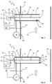
- the Fig. 2 shows the possibility of providing not only one opening 34 but a plurality of these openings 34 in the lance housing 32.
- the openings are arranged on the front side of the lance tip.
- a filter 35 is arranged in each of the openings 34.
- the openings 34 with the filters 35 could also be distributed over the region of the lance 30, which projects into the channel 26.
- FIG. 2 shows a further exemplary embodiment of the device 10 according to the invention, in which the device 10 is divided into two and has a first device part 50, which can be constructed like that of the first embodiment, and a second device part 52, which is arranged on the opposite side of the chimney 26 and in which, for example, the reflector 18 could be arranged.
- a second light receiver 54 may be arranged, which is arranged so that it can receive, for example, forward scattered light, so that with this meter 10 also on the principle of scattered light measurement, a concentration evaluation of gas fractions can be made.
- the scattered light received by the receiver 54 is evaluated in a second evaluation device 56 for this purpose.
- the first receiver 22 could also be arranged in the second device part 52 instead of the reflector 18.
- Fig. 4 shows a further embodiment in which, in contrast to the first or second, the measuring section 16 is shortened, that does not extend over the full lance length.
- the lance 30 here has a gas-tight, coaxially arranged inner tube 70, which has a window 74 at its reflector-side end 72, through which the light beam 14 exits.
- the measuring section 16 thus extends only from the window 74 to the reflector 18. This can be meaningful, because thus the measuring section 16 extends only in the region of the lance 30, in which the openings 34 are located, whereby more accurate measurement results can be obtained, because in this area, the process conditions are those in the gas guide channel 26 most similar.
- the measurement gas is pumped through the openings 34 with the filters 35 through the measuring section 16 and through a gap 76 between the further housing 32 and inner tube 70.
- the lance housing 32 has an outlet opening 80 through which the recirculated gas exits.
- the outlet opening 80 is arranged at the end of the lance housing 32.
- the gas entering the measuring section 16 through the opening 34 and the filter 35, which is indicated by the arrow 82, is conveyed through the measuring section 16 in the direction of the outlet opening 80 and discharged through the outlet opening 80 into the channel (arrows 84 and 86).
- the delivery of the measurement gas from the opening 34 to the outlet opening 80 is effected by virtue of the fact that the outlet opening 80 is part of an ejector 88 of the gas delivery device 36 designed as an ejector.
- the outlet 88 designed as an ejector at the end of a channel 90 thus effects a negative pressure, through which the sample gas is sucked out of the outlet opening 80, which in turn causes the sample gas to be sucked through the opening 34.
- the gas delivery device 36 may then be designed as a simple fan, is blown with the ambient air through the ejector 88 into the gas guide channel 26.
- condensate accumulating in the lance housing 30 is discharged through the outlet port 80 simultaneously with the gas.
- a drain device 92 is provided for condensate removal, which drains the condensate to the outlet opening 80. This allows the condensate not only run off easily, but is actively sucked out of the housing with the discharged gas.
- Fig. 6 shows a further embodiment.
- the measurement gas is as in the embodiments after Fig. 1 to 4 sucked through the opening 34 and the filter 35 by means of the gas conveyor 36 and conveyed into the measuring section 16.
- the opening 34 is closable with a disposable seal 94, in the manner of a non-return valve, which thus permits only one conveying direction into the interior of the lance housing 30.
- the outlet opening 80 can be closed with a second disposable seal 96 which opens only in the direction of the gas guide channel.
- the one-way seals 94 and 96 may be made of a thin membrane, as known from a diaphragm pump or gas mask.
- the sample gas is sucked through only the opening 34 and the filter 35.
- the one-way seal 96 of the outlet port 80 does not permit gas flow from the channel into the lance housing.
- the measuring gas flows through the measuring section 16 and is reintroduced via the gas conveying device 36 into the exhaust gas channel 26. Nevertheless, resulting condensate may drain via the downcomer 92 and drain into the duct 26 through the outlet port 80 because the disposable seal 96 permits flow in that direction.
Landscapes
- Physics & Mathematics (AREA)
- Health & Medical Sciences (AREA)
- Life Sciences & Earth Sciences (AREA)
- Chemical & Material Sciences (AREA)
- Analytical Chemistry (AREA)
- Biochemistry (AREA)
- General Health & Medical Sciences (AREA)
- General Physics & Mathematics (AREA)
- Immunology (AREA)
- Pathology (AREA)
- Spectroscopy & Molecular Physics (AREA)
- Investigating Or Analysing Materials By Optical Means (AREA)
Priority Applications (1)
| Application Number | Priority Date | Filing Date | Title |
|---|---|---|---|
| EP16159307.4A EP3112845B1 (fr) | 2016-03-09 | 2016-03-09 | Procédé d'analyse optique in situ d'un gaz de mesure |
Applications Claiming Priority (1)
| Application Number | Priority Date | Filing Date | Title |
|---|---|---|---|
| EP16159307.4A EP3112845B1 (fr) | 2016-03-09 | 2016-03-09 | Procédé d'analyse optique in situ d'un gaz de mesure |
Publications (2)
| Publication Number | Publication Date |
|---|---|
| EP3112845A1 true EP3112845A1 (fr) | 2017-01-04 |
| EP3112845B1 EP3112845B1 (fr) | 2018-01-24 |
Family
ID=55527813
Family Applications (1)
| Application Number | Title | Priority Date | Filing Date |
|---|---|---|---|
| EP16159307.4A Active EP3112845B1 (fr) | 2016-03-09 | 2016-03-09 | Procédé d'analyse optique in situ d'un gaz de mesure |
Country Status (1)
| Country | Link |
|---|---|
| EP (1) | EP3112845B1 (fr) |
Cited By (2)
| Publication number | Priority date | Publication date | Assignee | Title |
|---|---|---|---|---|
| CN107271365A (zh) * | 2017-08-23 | 2017-10-20 | 华纳创新(北京)科技有限公司 | 一种原位在线测定氨逃逸的装置 |
| DE102019129658A1 (de) * | 2019-11-04 | 2021-05-06 | Sick Ag | Vorrichtung zur optischen In-Situ Analyse eines Prozessgases |
Citations (10)
| Publication number | Priority date | Publication date | Assignee | Title |
|---|---|---|---|---|
| US4549080A (en) | 1983-06-17 | 1985-10-22 | Infrared Industries, Inc. | Double-pass flue gas analyzer |
| JPS60231137A (ja) * | 1984-04-30 | 1985-11-16 | Fuji Electric Co Ltd | 光学的ガス濃度計 |
| DE19947123A1 (de) * | 1999-09-30 | 2001-04-05 | Siemens Ag | Meßzelle zur Bestimmung eines gasförmigen Bestandteils der Atemluft |
| CN1414373A (zh) * | 2001-10-26 | 2003-04-30 | 韩宏峰 | 气态污染物微量抽取现场分析方法及装置 |
| EP1469299A1 (fr) * | 2003-04-16 | 2004-10-20 | ABB PATENT GmbH | Cuvette de mesure pour un photomètre, et méthode d'utilisation |
| US20080168851A1 (en) * | 2007-01-12 | 2008-07-17 | Martin Lopez | Probe |
| EP2416145A1 (fr) * | 2010-08-04 | 2012-02-08 | SICK MAIHAK GmbH | Dispositif destiné à l'analyse d'un fluide |
| JP2014002072A (ja) * | 2012-06-19 | 2014-01-09 | Horiba Ltd | ガス分析装置 |
| DE102014002087A1 (de) * | 2014-02-14 | 2015-08-20 | Abb Technology Ag | Spektroskopische Gasanalysevorrichtung und Verfahren dazu |
| WO2015193370A1 (fr) * | 2014-06-19 | 2015-12-23 | Danfoss Ixa A/S | Sonde pour capteur de gaz ayant une protection de gaz de purge |
-
2016
- 2016-03-09 EP EP16159307.4A patent/EP3112845B1/fr active Active
Patent Citations (10)
| Publication number | Priority date | Publication date | Assignee | Title |
|---|---|---|---|---|
| US4549080A (en) | 1983-06-17 | 1985-10-22 | Infrared Industries, Inc. | Double-pass flue gas analyzer |
| JPS60231137A (ja) * | 1984-04-30 | 1985-11-16 | Fuji Electric Co Ltd | 光学的ガス濃度計 |
| DE19947123A1 (de) * | 1999-09-30 | 2001-04-05 | Siemens Ag | Meßzelle zur Bestimmung eines gasförmigen Bestandteils der Atemluft |
| CN1414373A (zh) * | 2001-10-26 | 2003-04-30 | 韩宏峰 | 气态污染物微量抽取现场分析方法及装置 |
| EP1469299A1 (fr) * | 2003-04-16 | 2004-10-20 | ABB PATENT GmbH | Cuvette de mesure pour un photomètre, et méthode d'utilisation |
| US20080168851A1 (en) * | 2007-01-12 | 2008-07-17 | Martin Lopez | Probe |
| EP2416145A1 (fr) * | 2010-08-04 | 2012-02-08 | SICK MAIHAK GmbH | Dispositif destiné à l'analyse d'un fluide |
| JP2014002072A (ja) * | 2012-06-19 | 2014-01-09 | Horiba Ltd | ガス分析装置 |
| DE102014002087A1 (de) * | 2014-02-14 | 2015-08-20 | Abb Technology Ag | Spektroskopische Gasanalysevorrichtung und Verfahren dazu |
| WO2015193370A1 (fr) * | 2014-06-19 | 2015-12-23 | Danfoss Ixa A/S | Sonde pour capteur de gaz ayant une protection de gaz de purge |
Cited By (3)
| Publication number | Priority date | Publication date | Assignee | Title |
|---|---|---|---|---|
| CN107271365A (zh) * | 2017-08-23 | 2017-10-20 | 华纳创新(北京)科技有限公司 | 一种原位在线测定氨逃逸的装置 |
| DE102019129658A1 (de) * | 2019-11-04 | 2021-05-06 | Sick Ag | Vorrichtung zur optischen In-Situ Analyse eines Prozessgases |
| WO2021089408A1 (fr) | 2019-11-04 | 2021-05-14 | Sick Ag | Dispositif d'analyse optique in situ d'un gaz de procédé |
Also Published As
| Publication number | Publication date |
|---|---|
| EP3112845B1 (fr) | 2018-01-24 |
Similar Documents
| Publication | Publication Date | Title |
|---|---|---|
| EP1467194B2 (fr) | Procédé et dispositif pour la détection, caractérisation et/ou élimination de particules | |
| DE2543726A1 (de) | Geraet zur feststellung einer gasfoermigen verunreinigung | |
| EP1176414B1 (fr) | Procédé et dispositif pour déterminer des paramètres physiques collectifs des particules dans les gaz | |
| EP3788340A1 (fr) | Procédé permettant de déterminer la position relative d'une fuite de gaz | |
| WO2011061069A1 (fr) | Dispositif pour mesurer la concentration massique de poussière fine présente dans les gaz d'échappement de dispositifs de combustion de matière solide | |
| EP3104163B1 (fr) | Analyseur de gaz de processus et procédé d'analyse d'un gaz de processus | |
| EP3112845B1 (fr) | Procédé d'analyse optique in situ d'un gaz de mesure | |
| WO2020038658A1 (fr) | Système de mesure de particule pourvu d'un dispositif de dilution et procédé pour la mesure de particules | |
| DE102014101915B4 (de) | Vorrichtung und Verfahren zur Bestimmung der Konzentration zumindest eines Gases in einem Probengasstrom mittels Infrarotabsorptionsspektroskopie | |
| EP2378270B1 (fr) | Procédé de détermination d'une concentration de particules et dispositif de mesure | |
| WO2021089408A1 (fr) | Dispositif d'analyse optique in situ d'un gaz de procédé | |
| DE2521453C2 (fr) | ||
| DE202016101286U1 (de) | Vorrichtung zur optischen In-Situ Analyse eines Messgases | |
| WO1999009391A2 (fr) | Photometre a spectroscopie d'absorption non dispersive dans l'infrarouge (ndir) pour la mesure de plusieurs constituants | |
| EP1287335B1 (fr) | Procede et dispositif permettant de determiner la composition du melange de fluides quelconques et de mesurer la quantite de matiere | |
| EP2416145B1 (fr) | Dispositif destiné à l'analyse d'un fluide | |
| DE202016100234U1 (de) | Vorrichtung zur optischen In-Situ Analyse eines Messgases | |
| AT515495B1 (de) | Verfahren und Vorrichtung zur Bestimmung einer Partikelkonzentration eines mit Partikel geladenen Messgases | |
| DE102016111657B4 (de) | Vorrichtung zur optischen in-situ Gasanalyse | |
| WO2012123124A1 (fr) | Procédé et appareil de mesure pour la détermination d'atomes et de molécules dans des échantillons d'analyse | |
| DE102022119186B3 (de) | Gasanalysator zur optischen Gasanalyse | |
| AT515596B1 (de) | Partikelmessgerät und Verfahren zum Messen der Massenemission und der optischen Absorption eines partikelgeladenen Probengases | |
| DE202019106119U1 (de) | Vorrichtung zur optischen In-Situ Analyse eines Prozessgases | |
| EP3220132B1 (fr) | Système de mesure de gaz in situ pour réacteurs à gaz dans des environnements critiques | |
| DE202010010042U1 (de) | Einrichtung zur fotometrischen Messung in Gasen und Flüssigkeiten |
Legal Events
| Date | Code | Title | Description |
|---|---|---|---|
| PUAI | Public reference made under article 153(3) epc to a published international application that has entered the european phase |
Free format text: ORIGINAL CODE: 0009012 |
|
| 17P | Request for examination filed |
Effective date: 20161014 |
|
| AK | Designated contracting states |
Kind code of ref document: A1 Designated state(s): AL AT BE BG CH CY CZ DE DK EE ES FI FR GB GR HR HU IE IS IT LI LT LU LV MC MK MT NL NO PL PT RO RS SE SI SK SM TR |
|
| AX | Request for extension of the european patent |
Extension state: BA ME |
|
| GRAP | Despatch of communication of intention to grant a patent |
Free format text: ORIGINAL CODE: EPIDOSNIGR1 |
|
| RIC1 | Information provided on ipc code assigned before grant |
Ipc: G01N 21/53 20060101ALI20170914BHEP Ipc: G01N 1/22 20060101ALN20170914BHEP Ipc: G01N 21/3504 20140101AFI20170914BHEP Ipc: G01N 21/39 20060101ALN20170914BHEP Ipc: G01N 33/00 20060101ALN20170914BHEP Ipc: G01N 21/15 20060101ALN20170914BHEP Ipc: G01N 21/33 20060101ALN20170914BHEP |
|
| INTG | Intention to grant announced |
Effective date: 20171004 |
|
| GRAS | Grant fee paid |
Free format text: ORIGINAL CODE: EPIDOSNIGR3 |
|
| GRAA | (expected) grant |
Free format text: ORIGINAL CODE: 0009210 |
|
| AK | Designated contracting states |
Kind code of ref document: B1 Designated state(s): AL AT BE BG CH CY CZ DE DK EE ES FI FR GB GR HR HU IE IS IT LI LT LU LV MC MK MT NL NO PL PT RO RS SE SI SK SM TR |
|
| REG | Reference to a national code |
Ref country code: GB Ref legal event code: FG4D Free format text: NOT ENGLISH |
|
| REG | Reference to a national code |
Ref country code: CH Ref legal event code: EP |
|
| REG | Reference to a national code |
Ref country code: AT Ref legal event code: REF Ref document number: 966052 Country of ref document: AT Kind code of ref document: T Effective date: 20180215 |
|
| REG | Reference to a national code |
Ref country code: IE Ref legal event code: FG4D Free format text: LANGUAGE OF EP DOCUMENT: GERMAN |
|
| REG | Reference to a national code |
Ref country code: DE Ref legal event code: R096 Ref document number: 502016000484 Country of ref document: DE |
|
| REG | Reference to a national code |
Ref country code: FR Ref legal event code: PLFP Year of fee payment: 3 |
|
| REG | Reference to a national code |
Ref country code: NL Ref legal event code: MP Effective date: 20180124 |
|
| REG | Reference to a national code |
Ref country code: LT Ref legal event code: MG4D |
|
| PG25 | Lapsed in a contracting state [announced via postgrant information from national office to epo] |
Ref country code: NL Free format text: LAPSE BECAUSE OF FAILURE TO SUBMIT A TRANSLATION OF THE DESCRIPTION OR TO PAY THE FEE WITHIN THE PRESCRIBED TIME-LIMIT Effective date: 20180124 |
|
| PG25 | Lapsed in a contracting state [announced via postgrant information from national office to epo] |
Ref country code: HR Free format text: LAPSE BECAUSE OF FAILURE TO SUBMIT A TRANSLATION OF THE DESCRIPTION OR TO PAY THE FEE WITHIN THE PRESCRIBED TIME-LIMIT Effective date: 20180124 Ref country code: NO Free format text: LAPSE BECAUSE OF FAILURE TO SUBMIT A TRANSLATION OF THE DESCRIPTION OR TO PAY THE FEE WITHIN THE PRESCRIBED TIME-LIMIT Effective date: 20180424 Ref country code: CY Free format text: LAPSE BECAUSE OF FAILURE TO SUBMIT A TRANSLATION OF THE DESCRIPTION OR TO PAY THE FEE WITHIN THE PRESCRIBED TIME-LIMIT Effective date: 20180124 Ref country code: FI Free format text: LAPSE BECAUSE OF FAILURE TO SUBMIT A TRANSLATION OF THE DESCRIPTION OR TO PAY THE FEE WITHIN THE PRESCRIBED TIME-LIMIT Effective date: 20180124 Ref country code: LT Free format text: LAPSE BECAUSE OF FAILURE TO SUBMIT A TRANSLATION OF THE DESCRIPTION OR TO PAY THE FEE WITHIN THE PRESCRIBED TIME-LIMIT Effective date: 20180124 Ref country code: ES Free format text: LAPSE BECAUSE OF FAILURE TO SUBMIT A TRANSLATION OF THE DESCRIPTION OR TO PAY THE FEE WITHIN THE PRESCRIBED TIME-LIMIT Effective date: 20180124 |
|
| PG25 | Lapsed in a contracting state [announced via postgrant information from national office to epo] |
Ref country code: PL Free format text: LAPSE BECAUSE OF FAILURE TO SUBMIT A TRANSLATION OF THE DESCRIPTION OR TO PAY THE FEE WITHIN THE PRESCRIBED TIME-LIMIT Effective date: 20180124 Ref country code: LV Free format text: LAPSE BECAUSE OF FAILURE TO SUBMIT A TRANSLATION OF THE DESCRIPTION OR TO PAY THE FEE WITHIN THE PRESCRIBED TIME-LIMIT Effective date: 20180124 Ref country code: SE Free format text: LAPSE BECAUSE OF FAILURE TO SUBMIT A TRANSLATION OF THE DESCRIPTION OR TO PAY THE FEE WITHIN THE PRESCRIBED TIME-LIMIT Effective date: 20180124 Ref country code: BG Free format text: LAPSE BECAUSE OF FAILURE TO SUBMIT A TRANSLATION OF THE DESCRIPTION OR TO PAY THE FEE WITHIN THE PRESCRIBED TIME-LIMIT Effective date: 20180424 Ref country code: RS Free format text: LAPSE BECAUSE OF FAILURE TO SUBMIT A TRANSLATION OF THE DESCRIPTION OR TO PAY THE FEE WITHIN THE PRESCRIBED TIME-LIMIT Effective date: 20180124 Ref country code: IS Free format text: LAPSE BECAUSE OF FAILURE TO SUBMIT A TRANSLATION OF THE DESCRIPTION OR TO PAY THE FEE WITHIN THE PRESCRIBED TIME-LIMIT Effective date: 20180524 Ref country code: GR Free format text: LAPSE BECAUSE OF FAILURE TO SUBMIT A TRANSLATION OF THE DESCRIPTION OR TO PAY THE FEE WITHIN THE PRESCRIBED TIME-LIMIT Effective date: 20180425 |
|
| PG25 | Lapsed in a contracting state [announced via postgrant information from national office to epo] |
Ref country code: MT Free format text: LAPSE BECAUSE OF FAILURE TO SUBMIT A TRANSLATION OF THE DESCRIPTION OR TO PAY THE FEE WITHIN THE PRESCRIBED TIME-LIMIT Effective date: 20180124 |
|
| REG | Reference to a national code |
Ref country code: DE Ref legal event code: R097 Ref document number: 502016000484 Country of ref document: DE |
|
| PG25 | Lapsed in a contracting state [announced via postgrant information from national office to epo] |
Ref country code: AL Free format text: LAPSE BECAUSE OF FAILURE TO SUBMIT A TRANSLATION OF THE DESCRIPTION OR TO PAY THE FEE WITHIN THE PRESCRIBED TIME-LIMIT Effective date: 20180124 Ref country code: EE Free format text: LAPSE BECAUSE OF FAILURE TO SUBMIT A TRANSLATION OF THE DESCRIPTION OR TO PAY THE FEE WITHIN THE PRESCRIBED TIME-LIMIT Effective date: 20180124 Ref country code: RO Free format text: LAPSE BECAUSE OF FAILURE TO SUBMIT A TRANSLATION OF THE DESCRIPTION OR TO PAY THE FEE WITHIN THE PRESCRIBED TIME-LIMIT Effective date: 20180124 Ref country code: IT Free format text: LAPSE BECAUSE OF FAILURE TO SUBMIT A TRANSLATION OF THE DESCRIPTION OR TO PAY THE FEE WITHIN THE PRESCRIBED TIME-LIMIT Effective date: 20180124 |
|
| PG25 | Lapsed in a contracting state [announced via postgrant information from national office to epo] |
Ref country code: MC Free format text: LAPSE BECAUSE OF FAILURE TO SUBMIT A TRANSLATION OF THE DESCRIPTION OR TO PAY THE FEE WITHIN THE PRESCRIBED TIME-LIMIT Effective date: 20180124 Ref country code: SK Free format text: LAPSE BECAUSE OF FAILURE TO SUBMIT A TRANSLATION OF THE DESCRIPTION OR TO PAY THE FEE WITHIN THE PRESCRIBED TIME-LIMIT Effective date: 20180124 Ref country code: DK Free format text: LAPSE BECAUSE OF FAILURE TO SUBMIT A TRANSLATION OF THE DESCRIPTION OR TO PAY THE FEE WITHIN THE PRESCRIBED TIME-LIMIT Effective date: 20180124 Ref country code: SM Free format text: LAPSE BECAUSE OF FAILURE TO SUBMIT A TRANSLATION OF THE DESCRIPTION OR TO PAY THE FEE WITHIN THE PRESCRIBED TIME-LIMIT Effective date: 20180124 Ref country code: CZ Free format text: LAPSE BECAUSE OF FAILURE TO SUBMIT A TRANSLATION OF THE DESCRIPTION OR TO PAY THE FEE WITHIN THE PRESCRIBED TIME-LIMIT Effective date: 20180124 |
|
| PLBE | No opposition filed within time limit |
Free format text: ORIGINAL CODE: 0009261 |
|
| STAA | Information on the status of an ep patent application or granted ep patent |
Free format text: STATUS: NO OPPOSITION FILED WITHIN TIME LIMIT |
|
| REG | Reference to a national code |
Ref country code: BE Ref legal event code: MM Effective date: 20180331 |
|
| REG | Reference to a national code |
Ref country code: IE Ref legal event code: MM4A |
|
| PG25 | Lapsed in a contracting state [announced via postgrant information from national office to epo] |
Ref country code: LU Free format text: LAPSE BECAUSE OF NON-PAYMENT OF DUE FEES Effective date: 20180309 |
|
| 26N | No opposition filed |
Effective date: 20181025 |
|
| PG25 | Lapsed in a contracting state [announced via postgrant information from national office to epo] |
Ref country code: IE Free format text: LAPSE BECAUSE OF NON-PAYMENT OF DUE FEES Effective date: 20180309 |
|
| PG25 | Lapsed in a contracting state [announced via postgrant information from national office to epo] |
Ref country code: SI Free format text: LAPSE BECAUSE OF FAILURE TO SUBMIT A TRANSLATION OF THE DESCRIPTION OR TO PAY THE FEE WITHIN THE PRESCRIBED TIME-LIMIT Effective date: 20180124 Ref country code: BE Free format text: LAPSE BECAUSE OF NON-PAYMENT OF DUE FEES Effective date: 20180331 |
|
| REG | Reference to a national code |
Ref country code: CH Ref legal event code: PL |
|
| PG25 | Lapsed in a contracting state [announced via postgrant information from national office to epo] |
Ref country code: CH Free format text: LAPSE BECAUSE OF NON-PAYMENT OF DUE FEES Effective date: 20190331 Ref country code: LI Free format text: LAPSE BECAUSE OF NON-PAYMENT OF DUE FEES Effective date: 20190331 |
|
| PG25 | Lapsed in a contracting state [announced via postgrant information from national office to epo] |
Ref country code: TR Free format text: LAPSE BECAUSE OF FAILURE TO SUBMIT A TRANSLATION OF THE DESCRIPTION OR TO PAY THE FEE WITHIN THE PRESCRIBED TIME-LIMIT Effective date: 20180124 |
|
| PG25 | Lapsed in a contracting state [announced via postgrant information from national office to epo] |
Ref country code: PT Free format text: LAPSE BECAUSE OF FAILURE TO SUBMIT A TRANSLATION OF THE DESCRIPTION OR TO PAY THE FEE WITHIN THE PRESCRIBED TIME-LIMIT Effective date: 20180124 |
|
| PG25 | Lapsed in a contracting state [announced via postgrant information from national office to epo] |
Ref country code: MK Free format text: LAPSE BECAUSE OF NON-PAYMENT OF DUE FEES Effective date: 20180124 Ref country code: HU Free format text: LAPSE BECAUSE OF FAILURE TO SUBMIT A TRANSLATION OF THE DESCRIPTION OR TO PAY THE FEE WITHIN THE PRESCRIBED TIME-LIMIT; INVALID AB INITIO Effective date: 20160309 |
|
| REG | Reference to a national code |
Ref country code: AT Ref legal event code: MM01 Ref document number: 966052 Country of ref document: AT Kind code of ref document: T Effective date: 20210309 |
|
| PG25 | Lapsed in a contracting state [announced via postgrant information from national office to epo] |
Ref country code: AT Free format text: LAPSE BECAUSE OF NON-PAYMENT OF DUE FEES Effective date: 20210309 |
|
| REG | Reference to a national code |
Ref country code: DE Ref legal event code: R081 Ref document number: 502016000484 Country of ref document: DE Owner name: ENDRESS+HAUSER SICK GMBH+CO. KG, DE Free format text: FORMER OWNER: SICK AG, 79183 WALDKIRCH, DE |
|
| REG | Reference to a national code |
Ref country code: GB Ref legal event code: 732E Free format text: REGISTERED BETWEEN 20260102 AND 20260107 |
|
| PGFP | Annual fee paid to national office [announced via postgrant information from national office to epo] |
Ref country code: GB Payment date: 20260324 Year of fee payment: 11 |
|
| PGFP | Annual fee paid to national office [announced via postgrant information from national office to epo] |
Ref country code: DE Payment date: 20260320 Year of fee payment: 11 |
|
| PGFP | Annual fee paid to national office [announced via postgrant information from national office to epo] |
Ref country code: FR Payment date: 20260325 Year of fee payment: 11 |