EP3112893B1 - Détermination de l'emplacement d'un dispositif utilisateur - Google Patents
Détermination de l'emplacement d'un dispositif utilisateur Download PDFInfo
- Publication number
- EP3112893B1 EP3112893B1 EP16177480.7A EP16177480A EP3112893B1 EP 3112893 B1 EP3112893 B1 EP 3112893B1 EP 16177480 A EP16177480 A EP 16177480A EP 3112893 B1 EP3112893 B1 EP 3112893B1
- Authority
- EP
- European Patent Office
- Prior art keywords
- location
- premise
- user device
- access point
- zone
- Prior art date
- Legal status (The legal status is an assumption and is not a legal conclusion. Google has not performed a legal analysis and makes no representation as to the accuracy of the status listed.)
- Active
Links
Images

Classifications
-
- H—ELECTRICITY
- H04—ELECTRIC COMMUNICATION TECHNIQUE
- H04W—WIRELESS COMMUNICATION NETWORKS
- H04W4/00—Services specially adapted for wireless communication networks; Facilities therefor
- H04W4/30—Services specially adapted for particular environments, situations or purposes
- H04W4/33—Services specially adapted for particular environments, situations or purposes for indoor environments, e.g. buildings
-
- G—PHYSICS
- G01—MEASURING; TESTING
- G01S—RADIO DIRECTION-FINDING; RADIO NAVIGATION; DETERMINING DISTANCE OR VELOCITY BY USE OF RADIO WAVES; LOCATING OR PRESENCE-DETECTING BY USE OF THE REFLECTION OR RERADIATION OF RADIO WAVES; ANALOGOUS ARRANGEMENTS USING OTHER WAVES
- G01S5/00—Position-fixing by co-ordinating two or more direction or position line determinations; Position-fixing by co-ordinating two or more distance determinations
- G01S5/02—Position-fixing by co-ordinating two or more direction or position line determinations; Position-fixing by co-ordinating two or more distance determinations using radio waves
- G01S5/0252—Radio frequency fingerprinting
-
- H—ELECTRICITY
- H04—ELECTRIC COMMUNICATION TECHNIQUE
- H04W—WIRELESS COMMUNICATION NETWORKS
- H04W4/00—Services specially adapted for wireless communication networks; Facilities therefor
- H04W4/02—Services making use of location information
- H04W4/021—Services related to particular areas, e.g. point of interest [POI] services, venue services or geofences
Definitions
- the present subject matter relates in general, to location determination, in particular, to determining location of the user device in an indoor environment.
- location of a user device is computed based on known techniques such as trilateration and triangulation.
- the techniques usually determine distance of the user device from three or more signal sources to determine regions within each signal source in which the user device is located.
- the signal sources can be, for instance, GPS satellites, mobile signal towers, and Wi-Fi access points.
- the location of the user device is then determined based on portion of the regions that overlap.
- the techniques can be used to compute location of the user device for outdoor as well as indoor environments.
- location computation is performed by utilizing multiple access points that are distributed across an indoor premise.
- location of the user device may be computed to track employees for one or more purpose such as, providing location based services to the employees.
- One of the prior art paper of JIE YANG ET AL titled 'Indoor localization using improved RSS-Based Lateration methods' at Global Telecommunications Conference, GLOBECOM 2009 discloses location estimation.
- the paper further states that among the large class of localization schemes, RSS-based lateration methods have the advantage of providing closed-form solutions for mathematical analysis as compared to heuristic-based localization approaches.
- the localization accuracy of RSS-based lateration methods are significantly affected by the unpredictable setup in indoor environments.
- the paper discloses two approaches, regression-based and correlation-based.
- the regression-based approach uses linear regression to discover a better fit of Signal propagation model between RSS and the distance, while the correlation-based approach utilizes the correlation among RSS in local area to obtain more accurate signal propagation.
- the paper further mentions that the results using both Simulation as well as real experiments demonstrate that above said techniques outperform the original RSS-based lateration methods.
- method for determining location of a user device within a premise comprises, identifying a plurality of zones with physical boundaries within the premise based on parameters associated with geometry of the premise.
- the premise includes a plurality of access points distributed across the plurality of zones.
- the method further comprises collecting a first set of Received Signal Strength Indicator (RSSI) Data for each zone from amongst the plurality of zones, at different locations within each zone.
- RSSI data is representative of strength of signals received from accessible access points within a zone.
- VPLE Variable Path Loss Exponent
- a location detection system for determining location of a user device within a premise, the location detection system comprising; a processor, a zone prediction module coupled to the processor.
- the zone prediction module is to identify a zone from amongst a plurality of zones within the premise in which the user device is located. Each zone includes a physical boundary; and a data collection module coupled to the processor.
- the data collection module is to collect a second set of Received Signal Strength Indicator (RSSI) data, at the location of the user device, from each accessible access point from amongst a plurality of access points accessible within the zone.
- the RSSI data is representative of strength of signals received from each accessible access point within the zone; and a location module coupled to the data collection module.
- the location module is to compute distance of the user device from each accessible access point based on Variable Path Loss Exponent (VPLE) associated with each accessible access point accessible within the zone and the second set of RSSI data; and compute location coordinates of the user device based on the computed distances.
- VPLE Variable Path Loss Exponent
- the location coordinates are computed by utilizing a trilateration technique, wherein the trilateration technique utilizes the computed distances of the user device from at least three access points from amongst the plurality of access points to determine the location coordinates of the user device.
- the application provides a non-transitory computer-readable medium comprising instructions for determining location of a user device within a premise, executable by a processor resource to identify a plurality of zones with physical boundaries within the premise based on parameters associated with geometry of the premise, wherein the premise includes a plurality of access points distributed across the plurality of zones; collect a first set of Received Signal Strength Indicator (RSSI) Data at different locations within the premise, wherein the first set of RSSI data represents strength of signals received from each accessible access point within the premise, and wherein distance of each accessible access point from each location from amongst the different locations is predetermined; compute a Variable Path Loss Exponent (VPLE) within each zone for each accessible access point for determining location of the user device, wherein the VPLE for each zone is computed based on the first set of RSSI data, line of sight condition, a non-line of sight condition and the distance of each accessible access point from each location.
- RSSI Received Signal Strength Indicator
- VPLE
- Techniques for determining location of a user device are described. Conventionally, various techniques of indoor localization, for determining user location in an indoor environment, have been developed. One such technique leverages a trilateration or finger printing method to determine location of the user device. The technique utilizes past data, such as signals received at different locations and distance of the user device from three or more access points to determine location of the user device. The technique includes a training phase where a system is trained for an extended period of time before determining location of the user device.
- the training phase includes collecting datapoints related to location of the user device at different instances, and signals received during the instances at different locations.
- the datapoints can be, an employee sitting in a conference room at first floor of a building at a location A, a user device of the employee receiving signals of strength -85 dBm and -90 dBm from two access points that are accessible in the conference room, and the user device at a distance of 15 meters and 17 meters from the two access points, in respective order.
- the technique may collect the datapoints associated with the distance from a data store that stores information about different zones within a premise and their respective distances from one or more accessible access points.
- a database model is generated during the training phase based on the collected data.
- the generated database model stores all the datapoints collected at different instances in a structured format.
- a relationship between the datapoints is then derived based on the generated database model.
- the derived relationship between the datapoints can be, reception of signals with strength -85 dBm or less at the location A within the conference room.
- the accuracy of the relationship may be improved over time as more datapoints are collected.
- the relationship is then used to determine the location of the user device when one or more datapoints are predetermined. Thus, a substantial amount of time is needed to collect the datapoints and to derive the relationship between the datapoints.
- the technique utilizes a propagation model for computing distance of the user device from the access points based on the strength of signals received at the location of the user device.
- the propagation model uses fixed value of pathloss constant for computing the distance.
- the fixed value of path loss constant leads to inaccurate results of location determination for indoor environments where the settings are dynamic in nature such as, different materials used for different furniture, different cabinets, and walls within the premise, and moving or sliding doors within the premise.
- techniques for determining location of a user device are described.
- the described techniques are time efficient as they prevent extensive collection of datapoints and deriving relationship during the training phase of the system. Further, the described techniques are cost efficient as they prevent deployment of any additional infrastructure for the training phase. In addition, the described techniques provide a higher degree of accuracy in determining location of the user in a large indoor environment with multiple obstructions.
- a method for determining location of a user device within a premise includes identifying multiple zones with physical boundaries within the premise based on parameters associated with geometry of the premise.
- the premise includes multiple access points distributed across the multiple zones.
- the method thereafter includes collecting a first set of Received Signal Strength Indicator (RSSI) Data at different locations within the premise.
- RSSI data is representative of strength of signals received from each accessible access point within the premise that are accessible within a zone.
- the different locations may be selected based on a predetermined resolution from corresponding physical boundaries and the parameters associated with geometry of the premise.
- the RSSI data is representative of strength of signals received from each accessible access point within the premise that are accessible within a zone.
- distance of each location from each accessible access point within the zone may be predetermined. That is, the distance between each of the location and the accessible access points may be known. For example, three locations A 1 , A 2 , and A 3 are selected within a zone based on a predefined resolution of 5 meters from a common physical boundary, and two access points AP 1 and AP 2 are accessible within the zone.
- the distances of 12 m, 10m and 15m for the access point AP 1 from each location A 1 , A 2 , and A 3 may be known.
- distances of 9 m, 5m and 7m for the access point AP 2 from each location A 1 , A 2 , and A 3 may also be known.
- the distance may be computed based on the predetermined resolution and the parameters associated with geometry of the premise.
- VPLE Variable Path Loss Exponent
- a regression technique is used to compute the VPLE.
- the VPLE for each zone is computed based on the first set of RSSI data, a line of sight condition, and a non-line of sight condition and the distance of each accessible access point from each location.
- Techniques of the present subject matter provide a scalable method of determining location of the user device within the premise by computing VPLE within each zone for each accessible access point.
- the VPLE is computed based on dynamic indoor conditions such as changing number of obstructions, material of obstruction and thickness of such obstructions. Therefore, the location so determined is accurate for any indoor environment, such as, small, medium or large. Further, the described techniques prevent the extensive training phase of collecting large number of datapoints and deriving relationship between the datapoints thereby saving time and additional deployment costs.
- Fig. 1 illustrates an environment 100 according to an implementation of the present subject matter.
- the environment 100 may either be a public distributed environment or may be a private closed network environment.
- the environment 100 may include a location detection system 102 communicatively coupled to a user device 104 through a network 106.
- the user device 104 is located within a premise 108 that includes multiple zones 110-1, 110-2,... 110-n that are separated by physical boundaries.
- the premise 108 includes multiple access points 112-1, 112-2, ...., 112-n, collectively referred to as access points 112-n and individually referred to as access point 112, distributed across the multiple zones for receiving and transmitting wireless signals.
- the access points 112-1, 112-2 and 112-3 are communicatively coupled to the location detection system 102 through the network 106. Further, the location detection system 102 includes a location module 114 for determining location coordinates of the user device 104.
- the location detection system 102 may be one of a server, and a computing device that is located outside the premise 108 to compute location coordinates of the user device 104 within the premise 108. In an implementation, the location detection system 102 may be located within the premise 108 to determine location of the user device 104. In another implementation, the location detection system 102 may be a centrally located unit for determining location of one or more user devices located in one or more premises.
- the user device 104 may be a portable device that is capable of transmitting and receiving wireless signals from the location detection system 102.
- Examples of the user device 104 includes, personal digital assistants, smart phones, hand held devices, mobile phones, laptops and the like.
- the network 106 may be a wireless or a wired network, or a combination thereof.
- the network 106 can be a collection of individual networks, interconnected with each other and functioning as a single large network (e.g., the internet or an intranet). Examples of such individual networks include, but are not limited to, Global System for Mobile Communication (GSM) network, Universal Mobile Telecommunications System (UMTS) network, Personal Communications Service (PCS) network, Time Division Multiple Access (TDMA) network, Code Division Multiple Access (CDMA) network, Next Generation Network (NGN), Public Switched Telephone Network (PSTN), and Integrated Services Digital Network (ISDN).
- GSM Global System for Mobile Communication
- UMTS Universal Mobile Telecommunications System
- PCS Personal Communications Service
- TDMA Time Division Multiple Access
- CDMA Code Division Multiple Access
- NTN Next Generation Network
- PSTN Public Switched Telephone Network
- ISDN Integrated Services Digital Network
- the network 106 includes various network entities, such as transceivers, gateways, and routers; however, such details have been omitted for ease of understanding.
- the premise 108 is an office premise with three rooms as three zones, 110-1, 110-2 and 110-3. The zones are separated by physical boundaries as shown in the fig.1 .
- the location detection system 102 determines location of the user device 104, within the premise 108, based on various parameters.
- the parameters include signals received at the location of user device 104 from each access point 112, path loss associated with each access point 112, and distance of the user device 104 from each access point 112.
- the user device 104 is located in the zone 110-1
- the access point 112-1 is located within the same zone 110-1
- the access points 112-2 and 112-3 are located in zones 110-2 and 110-3 in respective order.
- the user device 104 receives the signals from the access points 112-1, 112-2 and 112-3.
- the strength of signals received by the user device 104 from the access points 112-1, 112-2, and 112-3 may vary based on distance of the user device 104 from the access points.
- the strength of signals received from the access point 112-1 may be high as access point 112-1 is located in vicinity of the user device 104 and within the same zone 110-1.
- the strength of signals received from the access points 112-2 and 112-3 may be lower than that of the signals received from the access point 112-1 as the access points 112-2 and 112-3 are located at a distance from the user device 104 and are located in the other zones 110-2 and 110-3 that are separated by physical boundaries.
- one or more access points that are accessible within a zone with substantial strength of signals may be termed accessible access points hereinafter.
- a location detection data indicative of strength of signals for instance -85dBm, may be recorded at the location of the user device 104.
- the location detection system 102 records the location detection data at the location of the user device 104. Thereafter, the location detection system 102 determines the zone in which the user device 104 is located based on the location detection data. For example, the location detection system 102 may identify the zone 110-1 in which the user device 104 is located based on the location detection data -85dBm. In another implementation, the user device 104 may record the location detection data and determine the zone in which it is located. Thereafter, the user device 104 may provide the information related to the identified zone to the location detection system 102.
- the information related to the identified zone and the location detection data is provided to the location module 114.
- the information of zone 110-1 and the location detection data -85dBm is provided to the location module 114.
- the location module 114 can be understood as a module for computing location coordinates using a model or a relationship between strength of signals and distance.
- a variable path loss information associated with each access point 112 is also provided to the location module 114.
- the variable path losses may be computed based on attenuation of the signals due to dynamic nature of the indoor environment, such as, changing number of obstructions, walls, different materials and thickness of obstructions, different types of furniture and doors within the premise.
- the location module 114 computes distance of the user device 104 from each accessible access point 112 based on the information related to the identified zone, the location detection data, and the variable path loss information. The location module 114 then computes the location of the user device 104 based on the distance.
- the explanation regarding functioning of the location detection system 102 and computation of the location have been further explained in detail with respect to the description of forthcoming figures.
- the location detection system 102 may include a processor(s) 200, an interface(s) 202, and a memory 204. Further, the location detection system 102 may include module(s) 206 and data 208.
- the processor 200 may be configured to fetch and execute computer-readable instructions stored in the memory 204.
- the processor 200 may be implemented as one or more microprocessors, microcomputers, microcontrollers, digital signal processors, central processing units, state machines, logic circuitries, and/or any devices that manipulate signals based on operational instructions.
- the functions of the various elements shown in the figure, including any functional blocks labelled as "processor(s)", may be provided through the use of dedicated hardware as well as hardware capable of executing software in association with appropriate software.
- processor When provided by a processor, the functions may be provided by a single dedicated processor, by a single shared processor, or by a plurality of individual processors, some of which may be shared.
- explicit use of the term "processor” should not be construed to refer exclusively to hardware capable of executing software, and may implicitly include, without limitation, digital signal processor (DSP) hardware, network processor, application specific integrated circuit (ASIC), field programmable gate array (FPGA), read only memory (ROM) for storing software, random access memory (RAM), non-volatile storage. Other hardware, conventional and/or custom, may also be included.
- DSP digital signal processor
- ASIC application specific integrated circuit
- FPGA field programmable gate array
- ROM read only memory
- RAM random access memory
- non-volatile storage Other hardware, conventional and/or custom, may also be included.
- the interface(s) 202 may include a variety of machine readable instructions-based interfaces and hardware interfaces that allow the location detection system 102 to interact with different entities, such as the processor 200, the module 206, and the data 208. Further, the interface(s) 202 may enable the components of the location detection system 102 to communicate with other location detection systems, and external repositories. The interface 202 may facilitate multiple communications within a wide variety of networks and protocol types, including wireless networks, wireless Local Area Network (WLAN), RAN, satellite-based network, etc.
- WLAN wireless Local Area Network
- RAN wireless Local Area Network
- satellite-based network etc.
- the memory 204 may be coupled to the processor 200 and may, among other capabilities, provide data and instructions for generating different requests.
- the memory 204 can include any computer-readable medium known in the art including, for example, volatile memory, such as static random access memory (SRAM) and dynamic random access memory (DRAM), and/or non-volatile memory, such as read only memory (ROM), erasable programmable ROM, flash memories, hard disks, optical disks, and magnetic tapes.
- volatile memory such as static random access memory (SRAM) and dynamic random access memory (DRAM)
- non-volatile memory such as read only memory (ROM), erasable programmable ROM, flash memories, hard disks, optical disks, and magnetic tapes.
- the module(s) 206 may include routines, programs, objects, components, data structures, and the like, which perform particular tasks or implement particular abstract data types.
- the module(s) 206 may further include modules that supplement applications on the location detection system 102, for example, modules of an operating system. Further, the module 206 can be implemented in hardware, instructions executed by a processing unit, or by a combination thereof.
- the module(s) 206 may be machine-readable instructions (software) which, when executed by a processor/processing unit, perform any of the described functionalities.
- the machine-readable instructions may be stored on an electronic memory device, hard disk, optical disk or other machine-readable storage medium or non-transitory medium.
- the machine-readable instructions can be also be downloaded to the storage medium via a network connection.
- the data 208 serves, amongst other things, as a repository for storing data that may be fetched, processed, received, or generated by one or more of the module(s) 206.
- the module(s) 206 may perform different functionalities which may include, but may not be limited to, determining a zone in which the user device 104 is located, collecting data related to signal strength at different locations, computing location coordinates for the user device 104. Further, the module(s) 206 may perform clustering of the data, and computing Variable Path Loss Exponent (VPLE). Accordingly, the module(s) 208 may include a zone prediction module 210, a data collection module 212, a location module 214, a clustering module 216, a VPLE module 218, and a communication module 220. The data 208 may include a geometry data 220, a location data 222 and other data 224 such as a database or a knowledge model.
- VPLE Variable Path Loss Exponent
- the zone prediction module 210 identifies the multiple zones 110 within the premise 108 based on the geometry data 220 and the location data 222.
- the geometry data 220 may include details about a floor plan of the premise 108, such as, area of the premise 108, multiple zones 110 and their boundaries.
- the location data 222 may include location details and distance of each access point 112 from each zone within the premise 108.
- the data collection module 212 formulates the location detection data related to strength of signals, for instance Wi-Fi signals, in terms of Received Signal Strength Indicator (RSSI) data at different locations within the premise 108.
- the different locations can be different synthetic points that are selected based on a predefined resolution within the boundaries of each zone and parameters associated with geometry of the premise.
- distance of each accessible access point from each location from amongst the different locations is predetermined. That is, the distance between each of the location and the accessible access points may be known.
- n is calculated empirically for all access points 112 with line of sight and non-line of sight condition.
- the non-line of sight condition is associated with one of, material of obstructions within the premise, thickness of the material, and an attenuation factor of the obstruction.
- the data collection module 212 may then collate the RSSI data in the database.
- the database may also be refined over time based on RSSI data collected in real time from several user devices to obtain a first set of RSSI data that is based on real time conditions.
- the VPLE module 216 computes a Variable Path Loss Exponent (VPLE) within each zone for each accessible access point 112.
- VPLE Variable Path Loss Exponent
- the VPLE for each zone is computed based on one of a first set of RSSI data, a line of sight condition, and a non-line of sight condition and the distance of each accessible point from each location. For instance, the VPLE module 216 computes a value V 1 for VPLE of the access point 112-1 in the zone 110-1, a value of V 2 for VPLE of the access point 112-2 in the zone 110-1 and V 3 for VPLE of the access point 112-3 in the zone 110-1. Similarly, the VPLE module 216 may compute the values of VPLEs for each access point in the zones 110-2 and 110-3.
- the VPLE is computed based on path loss exponents that are computed at each location from amongst the different locations based on the first set of RSSI data collected at each location and the distance of each accessible access point from each location. Thereafter, a regression technique, for instance, a linear regression technique, is applied to the computed path loss exponents to obtain the VPLE.
- a regression technique for instance, a linear regression technique
- the values 2.5, 3.5, and 3 may be values of path loss exponents computed for the access point 112-1 at the different locations within the zone 110-1. Thereafter, the linear regression technique may be applied to the path loss exponents to obtain a value of 3 as the value of VPLE for the access point 112-1 within the zone 110-1.
- the VPLE so computed is sensitive to the dynamic nature of indoor environments, such as, changing number of obstruction, walls, different material and thickness of obstructions, furniture and doors within the premise, and attenuation factors of the obstructions. Therefore, the VPLE provides an accurate estimation of the losses of strength that signals experience during propagation thereby facilitating in accurate location determination.
- the computation of the VPLE within each zone 110 for each access point 112 by the VPLE module 216 can be understood as completion of the calibration phase. Hence, after completion of the calibration phase, each zone 110 within the premise 108 may be calibrated with respective values of VPLEs for each access point 112.
- the VPLE module 216 provides the VPLE within each zone for each access point to the location module 114.
- the VPLE computed for each access point within each zone is stored in another database for later use by location module 114 for location determination.
- the zone prediction module 210 identifies the zone of the user device 104 based on known techniques, such as, biometric sensing, access card, Wi-Fi transceivers, and mobile docketing stations close to a zone. Thereafter, the zone prediction module 210 provides the identified zone to the location module 114.
- the data collection module 212 collects a second set of RSSI data at the location of the user device 104 and provides the second set of RSSI data to the location module 114.
- the user device 104 collects the second set of RSSI data and provide it to the location module 114 of the location detection system 102.
- the location module 114 receives the information related to the identified zone from the zone prediction module 210, the VPLE from the VPLE module 216, and the second set of RSSI data from the data collection module 212 during the location determination phase. The location module 114 then determines distance of the user device 104 from each accessible access point based on the information related to the identified zone, the VPLE, and the second set of RSSI data. In an example implementation, the location module 114 may utilize equation (1) to obtain the distance.
- Pd the signal strength received at the distance of d
- Pdi the signal strength received at the known distance of di
- n the path loss exponent that is derived based on attenuation model for indoor environment
- L a the attenuation factor depends on the building layout and construction material.
- the location module 114 After determining the distance of the user device 104 from each accessible access point 112, the location module 114 computes the location coordinates of the user device 104. The location module 114 computes the location coordinates based on a trilateriation technique that utilizes the distance of the user device from three or more accessible access points to determine the location coordinates of the user device 104. In an example implementation, the location module 114 may utilize a least square trilateration algorithm to compute the location coordinates. The determination of the location coordinates of the user device 104 can be understood as the completion of the location determination phase.
- the location coordinates represent exact location of the user device 104 within the identified zone 110-1 and may be one of, values of x-axis and y-axis within the identified zone 110-1, and distance of the user device 104 from each physical boundary of the identified zone 110-1.
- the location coordinates may be stored as an entry in the database along with a corresponding time instance and a day.
- the entry may later be used by the location detection system 102 to predict location coordinates of the user device 104 based on the corresponding time instant and the day.
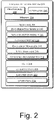
- Fig.3 and Fig. 4 illustrates method 300 and 400 in accordance according with implementations of the present subject matter.
- the order in which the methods 300 and 400 are described is not intended to be construed as a limitation, and any number of the described method blocks may be combined in any order to implement the methods 300 and 400 or an alternative method.
- the methods 300 and 400 may be implemented by processor(s) or computing system(s) through any suitable hardware, non-transitory machine readable instructions, or combination thereof.
- steps of the methods 300 and 400 may be performed by programmed computing systems.
- the steps of the methods 300 and 400 may be executed based on instructions stored in a non-transitory computer readable medium, as will be readily understood.
- the non-transitory computer readable medium may include, for example, digital memories, magnetic storage media, such as one or more magnetic disks and magnetic tapes, hard drives, or optically readable digital data storage media.
- the methods 300 and 400 may be executed by the location detection system 102, as described earlier.
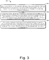
- Fig. 3 illustrates a method for calibrating multiple zones within a premise, according to the invention.
- block 302 multiple zones with physical boundaries are identified within a premise based on parameters associated with geometry of the premise.
- the premise includes multiple access points distributed across the multiple zones.
- the zone prediction module 210 identifies the multiple zones within the premise 108 based on the geometry data 220.
- a first set of Received Signal Strength Indicator (RSSI) data is collected at different locations within the premise.
- the RSSI data represents strength of signals received from each accessible access point in the premise.
- the data collection module 212 collects the first set of RSSI data at the different locations within the premise 108. Distance of each accessible access point from each location from amongst the different locations is predetermined
- a Variable Path Loss Exponent is computed within each zone for each accessible access point.
- the VPLE is computed based on the first set of RSSI data, a line of sight condition and a non-line of sight condition and the distance of each accessible access point from each location.
- the line of sight condition can be understood as signals that are received by the user device without any obstruction and the non-line of sight condition as a condition when the signals are received through the obstructions.
- the VPLE module 216 of the location detection system 102 computes the VPLE based on the line of sight condition and the non-line of sight condition.
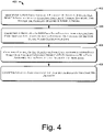
- Fig. 4 illustrates a method for determining location of a user device, according to the invention.
- a zone is identified from amongst the multiple zones within the premise where the user device is located.
- the zone prediction module 210 identifies the zone 110-1 in which the user device 104 is located.
- a second set of RSSI data is collected from each accessible access point at the location of the user device at block 404.
- the data collection module 212 collects the second set of RSSI data at the location of the user device 104
- distance of the user device from each accessible access point is computed based on the identified zone, the VPLE associated with each access point, and the second set of RSSI data received from each accessible access point.
- the distance is computed by the location module 114 based on the identified zone, the VPLE, and the second set of RSSI data.
- location coordinates of the user device are computed based on the computed distances at block 408.
- the location module 114 computes the location coordinates using the computed distances.
- the described method and system provide a higher degree of accuracy in computing location of the user device by utilizing dynamic nature of the obstructions within a premise and corresponding attenuation in strength of signals for computing the location. Further, the described method and system are time-efficient and prevent any dedicated infrastructure to be deployed thereby avoiding additional deployment costs.
- a computer-readable storage medium refers to any type of physical memory on which information or data readable by a processor may be stored.
- a computer-readable storage medium may store instructions for execution by one or more processors, including instructions for causing the processor(s) to perform steps or stages consistent with the embodiments described herein.
- the term "computer-readable medium” should be understood to include tangible items and exclude carrier waves and transient signals, i.e., be non-transitory. Examples include random access memory (RAM), read-only memory (ROM), volatile memory, nonvolatile memory, hard drives, CD ROMs, DVDs, flash drives, disks, and any other known physical storage media.
Landscapes
- Engineering & Computer Science (AREA)
- Computer Networks & Wireless Communication (AREA)
- Signal Processing (AREA)
- Physics & Mathematics (AREA)
- General Physics & Mathematics (AREA)
- Radar, Positioning & Navigation (AREA)
- Remote Sensing (AREA)
- Position Fixing By Use Of Radio Waves (AREA)
- Navigation (AREA)
Claims (9)
- Procédé de détermination de l'emplacement d'un dispositif utilisateur (104) dans un local, le procédé comprenant les étapes ci-dessous consistant à :identifier une pluralité de zones avec des limites physiques dans le local sur la base de paramètres associés à la géométrie du local, dans lequel le local inclut une pluralité de points d'accès répartis sur la pluralité de zones ;collecter un premier ensemble de données d'indicateur d'intensité de signal reçu (RSSI) pour chaque zone parmi la pluralité de zones, à différents emplacements au sein de chaque zone, dans lequel les données d'indicateur RSSI sont représentatives de l'intensité de signaux reçus en provenance de points d'accès accessibles au sein d'une zone, et dans lequel une distance de chaque point d'accès accessible par rapport à chaque emplacement parmi les différents emplacements est prédéterminée ; etcalculer un exposant de perte de chemin variable (VPLE) pour chaque point d'accès accessible au sein de chaque zone, sur la base du premier ensemble de données d'indicateur RSSI, des signaux reçus par le dispositif utilisateur (104) sans aucune obstruction dans le local, des signaux reçus par le dispositif utilisateur (104) à travers les obstructions dans le local et de la distance de chaque point d'accès accessible par rapport à chaque emplacement, en vue de déterminer l'emplacement du dispositif utilisateur (104), dans lequel l'exposant VPLE est calculé sur la base d'un exposant de perte de chemin à chaque point d'accès accessible au niveau de chaque emplacement parmi les différents emplacements, et l'exposant VPLE est sensible à la nature dynamique du local et à un ou plusieurs facteurs d'atténuation d'obstructions dans le local, et l'exposant VPLE fournit une estimation de pertes d'intensité de signaux pendant la propagation, dans lequel l'exposant VPLE est calculé en mettant en œuvre les étapes ci-dessous consistant à :calculer l'exposant de perte de chemin à chaque point d'accès accessible au niveau de chaque emplacement parmi les différents emplacements, sur la base du premier ensemble de données d'indicateur RSSI collecté à chaque emplacement et de la distance de chaque point d'accès accessible par rapport à chaque emplacement ; etappliquer une technique de régression aux exposants de perte de chemin calculés, en vue de calculer l'exposant VPLE ;identifier une zone parmi la pluralité de zones dans laquelle le dispositif utilisateur est situé, dans lequel chaque zone inclut une limite physique ;collecter un second ensemble de données d'indicateur RSSI, reçu en provenance de chaque point d'accès accessible au sein de la zone, à partir de l'emplacement du dispositif utilisateur au sein de la zone identifiée ;calculer une distance du dispositif utilisateur (104) par rapport à chaque point d'accès accessible, sur la base de l'exposant de perte de chemin variable (VPLE) associé à chaque point d'accès accessible au sein de la zone, et du second ensemble de données d'indicateur RSSI ; etcalculer des coordonnées d'emplacement du dispositif utilisateur (104) sur la base de la distance calculée, dans lequel les coordonnées d'emplacement sont calculées en utilisant une technique de trilatération, dans lequel la technique de trilatération utilise les distances calculées du dispositif utilisateur (104) à partir d'au moins trois points d'accès accessibles parmi la pluralité de points d'accès, en vue de déterminer les coordonnées d'emplacement du dispositif utilisateur (104).
- Procédé selon la revendication 1, dans lequel la géométrie du local inclut des données associées à au moins l'une parmi une surface du local et une limite de chaque zone.
- Procédé selon la revendication 1, dans lequel les signaux reçus par le dispositif utilisateur à travers les obstructions dans le local sont associés à au moins l'un des éléments parmi un matériau d'obstructions au sein du local, une épaisseur du matériau, et un facteur d'atténuation de l'obstruction.
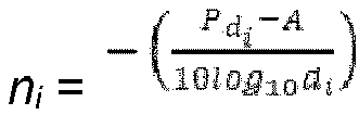
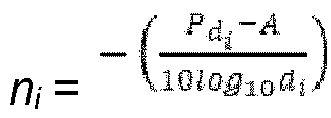
- Procédé selon la revendication 1, dans lequel l'exposant de perte de chemin est calculé pour chaque point d'accès sur la base des signaux reçus par le dispositif utilisateur sans aucune obstruction dans le local, et des signaux reçus par le dispositif utilisateur à travers les obstructions dans le local, dans lequel l'exposant de perte de chemin ni , à chaque emplacement, pour chacun des points d'accès accessibles, est calculé en utilisant l'équation :
- Système de détection d'emplacement (102) destiné à déterminer l'emplacement d'un dispositif utilisateur (104) dans un local, le système de détection d'emplacement (102) comprenant :un processeur (200) ;un module de prédiction de zone (210) couplé au processeur (200), pour identifier une pluralité de zones avec des limites physiques, au sein du local, sur la base de paramètres associés à la géométrie du local, dans lequel le local inclut une pluralité de points d'accès répartis à travers la pluralité de zones ;un module de collecte de données (212), couplé au processeur (200), pour collecter un premier ensemble de données d'indicateur RSSI à différents emplacements dans le local, dans lequel une distance de chaque point d'accès accessible par rapport à chaque emplacement parmi les différents emplacements est prédéterminée ; etun module d'exposant de perte de chemin variable (VPLE) (214), couplé au processeur (200), pour calculer un exposant VPLE pour chaque point d'accès au sein de chaque zone, sur la base du premier ensemble de données d'indicateur RSSI, des signaux reçus par le dispositif utilisateur (104) sans aucune obstruction dans le local, et des signaux reçus par le dispositif utilisateur (104) à travers les obstructions dans le local, dans lequel l'exposant VPLE est calculé sur la base d'un exposant de perte de chemin à chaque emplacement parmi les différents emplacements, et l'exposant VPLE est sensible à la nature dynamique du local et à un ou plusieurs facteurs d'atténuation d'obstructions dans le local, et l'exposant VPLE fournit une estimation de pertes d'intensité de signaux pendant la propagation, et dans lequel le module d'exposant de perte de chemin variable (VPLE) (214) est apte à calculer l'exposant VPLE :en calculant les exposants de perte de chemin à chaque point d'accès accessible au niveau de chaque emplacement parmi les différents emplacements, sur la base du premier ensemble de données d'indicateur RSSI collecté à chaque emplacement et de la distance de chaque point d'accès accessible par rapport à chaque emplacement ; eten appliquant une technique de régression aux exposants de perte de chemin calculés en vue de calculer l'exposant VPLE ;le module de prédiction de zone (210) est apte à identifier une zone parmi la pluralité de zones dans le local dans laquelle le dispositif utilisateur est situé, dans lequel chaque zone inclut une limite physique ;le module de collecte de données (212) est apte à collecter un second ensemble de données d'indicateur d'intensité de signal reçu (RSSI), à l'emplacement du dispositif utilisateur, à partir de chaque point d'accès accessible parmi une pluralité de points d'accès accessibles dans la zone, dans lequel les données d'indicateur RSSI sont représentatives de l'intensité de signaux reçus à partir de chaque point d'accès accessible dans la zone ; etle module d'emplacement (214), couplé au module de collecte de données (212), est apte à :calculer la distance du dispositif utilisateur par rapport à chaque point d'accès accessible, sur la base de l'exposant VPLE associé à chaque point d'accès accessible dans la zone et du second ensemble de données d'indicateur RSSI ; etcalculer des coordonnées d'emplacement du dispositif utilisateur sur la base des distances calculées, dans lequel les coordonnées d'emplacement sont calculées en utilisant une technique de trilatération, dans lequel la technique de trilatération utilise les distances calculées du dispositif utilisateur à partir d'au moins trois points d'accès parmi la pluralité de points d'accès, en vue de déterminer les coordonnées d'emplacement du dispositif utilisateur.
- Système de détection d'emplacement (102) selon la revendication 5, dans lequel les signaux reçus par le dispositif utilisateur à travers les obstructions dans le local correspondent à un matériau d'une obstruction dans le local, à l'épaisseur du matériau, et à un facteur d'atténuation de l'obstruction.
- Système de détection d'emplacement (102) selon la revendication 5, dans lequel l'exposant de perte de chemin est calculé pour chaque point d'accès sur la base des signaux reçus par le dispositif utilisateur sans aucune obstruction dans le local, et des signaux reçus par le dispositif utilisateur à travers les obstructions dans le local, dans lequel l'exposant de perte de chemin ni , à chaque emplacement, pour chacun des points d'accès accessibles, est calculé en utilisant l'équation :

- Support non transitoire lisible par ordinateur comprenant des instructions pour déterminer l'emplacement d'un dispositif utilisateur (104) au sein d'un local, exécutables par une ressource de processeur (200) pour :identifier une pluralité de zones avec des limites physiques dans le local sur la base de paramètres associés à la géométrie du local, dans lequel le local inclut une pluralité de points d'accès répartis sur la pluralité de zones ;collecter un premier ensemble de données d'indicateur d'intensité de signal reçu (RSSI) à différents emplacements au sein du local, dans lequel le premier ensemble de données d'indicateur RSSI représente une intensité de signaux reçus en provenance de chaque point d'accès accessible au sein du local, et dans lequel une distance de chaque point d'accès accessible par rapport à chaque emplacement parmi les différents emplacements est prédéterminée ; etcalculer un exposant de perte de chemin variable (VPLE) au sein de chaque zone pour chaque point d'accès accessible, sur la base du premier ensemble de données d'indicateur RSSI, des signaux reçus par le dispositif utilisateur sans aucune obstruction dans le local, des signaux reçus par le dispositif utilisateur à travers les obstructions dans le local et de la distance de chaque point d'accès accessible par rapport à chaque emplacement, dans lequel l'exposant VPLE est calculé sur la base d'un exposant de perte de chemin à chaque emplacement parmi les différents emplacements, et l'exposant VPLE est sensible à la nature dynamique du local et à des facteurs d'atténuation d'obstructions dans le local, et l'exposant VPLE fournit une estimation de pertes d'intensité de signaux pendant la propagation, dans lequel l'étape de calcul de l'exposant VPLE comprend les étapes ci-dessous consistant à :calculer les exposants de perte de chemin à chaque point d'accès accessible au niveau de chaque emplacement parmi les différents emplacements, sur la base du premier ensemble de données d'indicateur RSSI collecté à chaque emplacement et de la distance de chaque point d'accès accessible par rapport à chaque emplacement ;appliquer une technique de régression aux exposants de perte de chemin calculés, en vue de calculer l'exposant VPLE ;identifier une zone parmi la pluralité de zones dans laquelle le dispositif utilisateur est situé, dans lequel chaque zone inclut une limite physique ;collecter un second ensemble de données d'indicateur RSSI, reçu en provenance de chaque point d'accès accessible au sein de la zone, à partir de l'emplacement du dispositif utilisateur au sein de la zone identifiée ;calculer une distance du dispositif utilisateur par rapport à chaque point d'accès accessible, sur la base de l'exposant de perte de chemin variable (VPLE) associé à chaque point d'accès accessible au sein de la zone, et du second ensemble de données d'indicateur RSSI ; etcalculer des coordonnées d'emplacement du dispositif utilisateur sur la base de la distance calculée, dans lequel les coordonnées d'emplacement sont calculées en utilisant une technique de trilatération, dans lequel la technique de trilatération utilise les distances calculées du dispositif utilisateur à partir d'au moins trois points d'accès accessibles parmi la pluralité de points d'accès, en vue de déterminer les coordonnées d'emplacement du dispositif utilisateur.
- Support non transitoire lisible par ordinateur selon la revendication 8, dans lequel l'exposant de perte de chemin est calculé pour chaque point d'accès sur la base des signaux reçus par le dispositif utilisateur sans aucune obstruction dans le local, et des signaux reçus par le dispositif utilisateur à travers les obstructions dans le local, dans lequel l'exposant de perte de chemin ni , à chaque emplacement, pour chacun des points d'accès accessibles, est calculé en utilisant l'équation :
Applications Claiming Priority (1)
| Application Number | Priority Date | Filing Date | Title |
|---|---|---|---|
| IN2540MU2015 | 2015-07-02 |
Publications (2)
| Publication Number | Publication Date |
|---|---|
| EP3112893A1 EP3112893A1 (fr) | 2017-01-04 |
| EP3112893B1 true EP3112893B1 (fr) | 2022-08-17 |
Family
ID=56292584
Family Applications (1)
| Application Number | Title | Priority Date | Filing Date |
|---|---|---|---|
| EP16177480.7A Active EP3112893B1 (fr) | 2015-07-02 | 2016-07-01 | Détermination de l'emplacement d'un dispositif utilisateur |
Country Status (4)
| Country | Link |
|---|---|
| US (1) | US9967715B2 (fr) |
| EP (1) | EP3112893B1 (fr) |
| AU (1) | AU2016204607B2 (fr) |
| SG (1) | SG10201605439XA (fr) |
Families Citing this family (11)
| Publication number | Priority date | Publication date | Assignee | Title |
|---|---|---|---|---|
| CN106961668A (zh) * | 2017-03-30 | 2017-07-18 | 努比亚技术有限公司 | 移动终端定位装置及方法 |
| CN107396280A (zh) * | 2017-06-12 | 2017-11-24 | 东南大学 | 一种基于rssi的室内定位系统和方法 |
| CN107801147A (zh) * | 2017-07-21 | 2018-03-13 | 西安工程大学 | 一种基于rssi测距改进的多区域自适应室内定位方法 |
| CN108495265B (zh) * | 2018-04-19 | 2020-07-03 | 北京邮电大学 | 一种室内定位方法、装置及计算设备 |
| US11006383B2 (en) * | 2018-11-15 | 2021-05-11 | Arizona Board Of Regents On Behalf Of Arizona State University | Mapping and localization using image processing of wireless signals |
| US10694053B1 (en) | 2019-01-22 | 2020-06-23 | Xerox Corporation | Wireless location tracking tag for monitoring real time location-tracking apparatus for an electronic device |
| US11728571B2 (en) | 2019-07-12 | 2023-08-15 | Arizona Board Of Regents On Behalf Of Arizona State University | Large intelligent surfaces with sparse channel sensors |
| US11009583B1 (en) | 2019-12-23 | 2021-05-18 | At&T Intellectual Property I, L.P. | Refining and selecting timing data to increase accuracy of timing-based location for user equipment |
| US11356800B2 (en) * | 2020-08-27 | 2022-06-07 | Xerox Corporation | Method of estimating indoor location of a device |
| CN112348631B (zh) * | 2020-10-27 | 2023-05-23 | 贝壳技术有限公司 | 一种推荐相似房源的方法、装置、电子设备及存储介质 |
| CN118632343A (zh) * | 2023-03-10 | 2024-09-10 | 台达电子工业股份有限公司 | 未授权装置的检测系统及其检测方法 |
Family Cites Families (16)
| Publication number | Priority date | Publication date | Assignee | Title |
|---|---|---|---|---|
| US7787891B2 (en) * | 2006-12-20 | 2010-08-31 | Intel Corporation | Mobile station localization apparatus, systems, and methods |
| CA2779126C (fr) * | 2009-10-30 | 2015-12-29 | Tata Consultancy Services Ltd. | Systeme d'estimation d'emplacements sans fil au moyen d'emetteurs-recepteurs radio a diversite de polarisation |
| KR100994840B1 (ko) | 2009-11-27 | 2010-11-16 | 주식회사 케이티 | 무선랜 신호 세기 기반의 실내 측위 방법 및 시스템 |
| US9853847B2 (en) * | 2009-12-30 | 2017-12-26 | Mediatek Inc. | Measurement and carrier group based optimization in wireless OFDM multi-carrier communication systems |
| US8077090B1 (en) * | 2010-06-15 | 2011-12-13 | Microsoft Corp. | Simultaneous localization and RF modeling |
| US8669902B2 (en) * | 2010-09-03 | 2014-03-11 | Cisco Technology, Inc. | Location estimation for wireless devices |
| US8750895B2 (en) * | 2011-06-03 | 2014-06-10 | Apple Inc. | Monitoring a geofence using wireless access points |
| US10237688B2 (en) * | 2011-08-18 | 2019-03-19 | Rivada Research, Llc | Method and system for improving the location of fixed wireless CBSD nodes |
| US9194935B2 (en) * | 2012-05-08 | 2015-11-24 | Texas Instruments Incorporated | Wireless local area network based positioning |
| US20140064112A1 (en) * | 2012-09-06 | 2014-03-06 | Qualcomm Incorporated | Context-based position determination |
| US9318885B2 (en) | 2012-11-09 | 2016-04-19 | Medashield Technologies, LLC | Protective sheath device with mounting piece for lead wire cables |
| GB201222376D0 (en) * | 2012-12-12 | 2013-01-23 | Al Najjar Ahmad | System and method for determining a postion of a mobile unit |
| US10015737B2 (en) * | 2013-11-12 | 2018-07-03 | Taiwan Semiconductor Manufacturing Co., Ltd. | Network selection recommender system and method |
| IN2014MU00776A (fr) * | 2014-03-07 | 2015-09-25 | Tata Consultancy Services Ltd | |
| US9743254B2 (en) * | 2015-04-30 | 2017-08-22 | Mist Systems, Inc. | Methods and apparatus relating to the use of received signals to determine wireless terminal location and/or refine location determination models |
| US9780888B2 (en) * | 2015-05-12 | 2017-10-03 | Qualcomm Incorporated | Techniques for mitigating cross device co-existence interference |
-
2016
- 2016-07-01 EP EP16177480.7A patent/EP3112893B1/fr active Active
- 2016-07-01 SG SG10201605439XA patent/SG10201605439XA/en unknown
- 2016-07-01 US US15/200,781 patent/US9967715B2/en active Active - Reinstated
- 2016-07-04 AU AU2016204607A patent/AU2016204607B2/en active Active
Also Published As
| Publication number | Publication date |
|---|---|
| SG10201605439XA (en) | 2017-02-27 |
| EP3112893A1 (fr) | 2017-01-04 |
| US9967715B2 (en) | 2018-05-08 |
| US20170006436A1 (en) | 2017-01-05 |
| AU2016204607A1 (en) | 2017-01-19 |
| AU2016204607B2 (en) | 2020-03-12 |
Similar Documents
| Publication | Publication Date | Title |
|---|---|---|
| EP3112893B1 (fr) | Détermination de l'emplacement d'un dispositif utilisateur | |
| CN104853379B (zh) | 一种无线网络质量评估方法及装置 | |
| CN112218330B (zh) | 定位方法及通信装置 | |
| Macarulla Rodriguez et al. | Google timeline accuracy assessment and error prediction | |
| WO2013085516A1 (fr) | Détection localisation au moyen d'une empreinte d'évanouissement de canal | |
| KR101328328B1 (ko) | 로그 데이터를 이용한 장소 추정 장치 및 그 방법 | |
| US10520578B2 (en) | Checking fingerprint samples for a radio model | |
| US9544732B2 (en) | Mobile communication system | |
| US9651654B2 (en) | Correcting device error radius estimates in positioning systems | |
| US9568588B2 (en) | Geolocation of wireless access points for wireless platforms | |
| US20210240745A1 (en) | Matching location-related information with name information of points of interest | |
| JP6025692B2 (ja) | エリア品質劣化推定装置及び方法 | |
| US20250056495A1 (en) | Systems and methods for predicting user location from radio data of telecommunication network | |
| CN106796277B (zh) | 移动通信网络中的位置调整 | |
| Liu et al. | A wireless location system in LTE networks | |
| AU2016433153B2 (en) | Estimated user location from cellular telephony data | |
| CN118338349A (zh) | 5g测量报告的定位方法、装置、设备和介质 | |
| Grzechca et al. | Indoor localization of objects based on RSSI and MEMS sensors | |
| Kaushal et al. | Improving accuracy of beacon-based indoor positioning system using weighted adaptive KNN algorithm | |
| US12013469B2 (en) | Sensor privacy management | |
| Le et al. | Convert wi-fi signals for fingerprint localization algorithm | |
| WO2016174655A1 (fr) | Positionnement du dernier kilomètre d'un dispositif de communications mobiles | |
| Estrada et al. | Evaluation of ML-based Positioning Systems with RSSI Measured on the User's Device or APs | |
| CN118488548A (zh) | 一种室内移动设备的定位系统、方法、电子设备及介质 | |
| CN119893660A (zh) | 定位方法、装置及系统 |
Legal Events
| Date | Code | Title | Description |
|---|---|---|---|
| PUAI | Public reference made under article 153(3) epc to a published international application that has entered the european phase |
Free format text: ORIGINAL CODE: 0009012 |
|
| STAA | Information on the status of an ep patent application or granted ep patent |
Free format text: STATUS: THE APPLICATION HAS BEEN PUBLISHED |
|
| AK | Designated contracting states |
Kind code of ref document: A1 Designated state(s): AL AT BE BG CH CY CZ DE DK EE ES FI FR GB GR HR HU IE IS IT LI LT LU LV MC MK MT NL NO PL PT RO RS SE SI SK SM TR |
|
| AX | Request for extension of the european patent |
Extension state: BA ME |
|
| STAA | Information on the status of an ep patent application or granted ep patent |
Free format text: STATUS: REQUEST FOR EXAMINATION WAS MADE |
|
| RIN1 | Information on inventor provided before grant (corrected) |
Inventor name: CHAKRAVAR, TAPAS Inventor name: GHOSE, AVIK Inventor name: AHMED, NASIMUDDIN Inventor name: PAL, ARPAN |
|
| 17P | Request for examination filed |
Effective date: 20170704 |
|
| RBV | Designated contracting states (corrected) |
Designated state(s): AL AT BE BG CH CY CZ DE DK EE ES FI FR GB GR HR HU IE IS IT LI LT LU LV MC MK MT NL NO PL PT RO RS SE SI SK SM TR |
|
| RIN1 | Information on inventor provided before grant (corrected) |
Inventor name: GHOSE, AVIK Inventor name: AHMED, NASIMUDDIN Inventor name: CHAKRAVAR, TAPAS Inventor name: PAL, ARPAN |
|
| STAA | Information on the status of an ep patent application or granted ep patent |
Free format text: STATUS: EXAMINATION IS IN PROGRESS |
|
| 17Q | First examination report despatched |
Effective date: 20191030 |
|
| GRAP | Despatch of communication of intention to grant a patent |
Free format text: ORIGINAL CODE: EPIDOSNIGR1 |
|
| STAA | Information on the status of an ep patent application or granted ep patent |
Free format text: STATUS: GRANT OF PATENT IS INTENDED |
|
| INTG | Intention to grant announced |
Effective date: 20220225 |
|
| GRAS | Grant fee paid |
Free format text: ORIGINAL CODE: EPIDOSNIGR3 |
|
| GRAA | (expected) grant |
Free format text: ORIGINAL CODE: 0009210 |
|
| STAA | Information on the status of an ep patent application or granted ep patent |
Free format text: STATUS: THE PATENT HAS BEEN GRANTED |
|
| AK | Designated contracting states |
Kind code of ref document: B1 Designated state(s): AL AT BE BG CH CY CZ DE DK EE ES FI FR GB GR HR HU IE IS IT LI LT LU LV MC MK MT NL NO PL PT RO RS SE SI SK SM TR |
|
| REG | Reference to a national code |
Ref country code: CH Ref legal event code: EP |
|
| REG | Reference to a national code |
Ref country code: DE Ref legal event code: R096 Ref document number: 602016074309 Country of ref document: DE |
|
| REG | Reference to a national code |
Ref country code: IE Ref legal event code: FG4D |
|
| REG | Reference to a national code |
Ref country code: AT Ref legal event code: REF Ref document number: 1512530 Country of ref document: AT Kind code of ref document: T Effective date: 20220915 |
|
| REG | Reference to a national code |
Ref country code: NL Ref legal event code: FP |
|
| REG | Reference to a national code |
Ref country code: LT Ref legal event code: MG9D |
|
| PG25 | Lapsed in a contracting state [announced via postgrant information from national office to epo] |
Ref country code: SE Free format text: LAPSE BECAUSE OF FAILURE TO SUBMIT A TRANSLATION OF THE DESCRIPTION OR TO PAY THE FEE WITHIN THE PRESCRIBED TIME-LIMIT Effective date: 20220817 Ref country code: RS Free format text: LAPSE BECAUSE OF FAILURE TO SUBMIT A TRANSLATION OF THE DESCRIPTION OR TO PAY THE FEE WITHIN THE PRESCRIBED TIME-LIMIT Effective date: 20220817 Ref country code: PT Free format text: LAPSE BECAUSE OF FAILURE TO SUBMIT A TRANSLATION OF THE DESCRIPTION OR TO PAY THE FEE WITHIN THE PRESCRIBED TIME-LIMIT Effective date: 20221219 Ref country code: NO Free format text: LAPSE BECAUSE OF FAILURE TO SUBMIT A TRANSLATION OF THE DESCRIPTION OR TO PAY THE FEE WITHIN THE PRESCRIBED TIME-LIMIT Effective date: 20221117 Ref country code: LV Free format text: LAPSE BECAUSE OF FAILURE TO SUBMIT A TRANSLATION OF THE DESCRIPTION OR TO PAY THE FEE WITHIN THE PRESCRIBED TIME-LIMIT Effective date: 20220817 Ref country code: LT Free format text: LAPSE BECAUSE OF FAILURE TO SUBMIT A TRANSLATION OF THE DESCRIPTION OR TO PAY THE FEE WITHIN THE PRESCRIBED TIME-LIMIT Effective date: 20220817 Ref country code: FI Free format text: LAPSE BECAUSE OF FAILURE TO SUBMIT A TRANSLATION OF THE DESCRIPTION OR TO PAY THE FEE WITHIN THE PRESCRIBED TIME-LIMIT Effective date: 20220817 Ref country code: ES Free format text: LAPSE BECAUSE OF FAILURE TO SUBMIT A TRANSLATION OF THE DESCRIPTION OR TO PAY THE FEE WITHIN THE PRESCRIBED TIME-LIMIT Effective date: 20220817 |
|
| REG | Reference to a national code |
Ref country code: AT Ref legal event code: MK05 Ref document number: 1512530 Country of ref document: AT Kind code of ref document: T Effective date: 20220817 |
|
| PG25 | Lapsed in a contracting state [announced via postgrant information from national office to epo] |
Ref country code: PL Free format text: LAPSE BECAUSE OF FAILURE TO SUBMIT A TRANSLATION OF THE DESCRIPTION OR TO PAY THE FEE WITHIN THE PRESCRIBED TIME-LIMIT Effective date: 20220817 Ref country code: IS Free format text: LAPSE BECAUSE OF FAILURE TO SUBMIT A TRANSLATION OF THE DESCRIPTION OR TO PAY THE FEE WITHIN THE PRESCRIBED TIME-LIMIT Effective date: 20221217 Ref country code: HR Free format text: LAPSE BECAUSE OF FAILURE TO SUBMIT A TRANSLATION OF THE DESCRIPTION OR TO PAY THE FEE WITHIN THE PRESCRIBED TIME-LIMIT Effective date: 20220817 Ref country code: GR Free format text: LAPSE BECAUSE OF FAILURE TO SUBMIT A TRANSLATION OF THE DESCRIPTION OR TO PAY THE FEE WITHIN THE PRESCRIBED TIME-LIMIT Effective date: 20221118 |
|
| PG25 | Lapsed in a contracting state [announced via postgrant information from national office to epo] |
Ref country code: SM Free format text: LAPSE BECAUSE OF FAILURE TO SUBMIT A TRANSLATION OF THE DESCRIPTION OR TO PAY THE FEE WITHIN THE PRESCRIBED TIME-LIMIT Effective date: 20220817 Ref country code: RO Free format text: LAPSE BECAUSE OF FAILURE TO SUBMIT A TRANSLATION OF THE DESCRIPTION OR TO PAY THE FEE WITHIN THE PRESCRIBED TIME-LIMIT Effective date: 20220817 Ref country code: DK Free format text: LAPSE BECAUSE OF FAILURE TO SUBMIT A TRANSLATION OF THE DESCRIPTION OR TO PAY THE FEE WITHIN THE PRESCRIBED TIME-LIMIT Effective date: 20220817 Ref country code: CZ Free format text: LAPSE BECAUSE OF FAILURE TO SUBMIT A TRANSLATION OF THE DESCRIPTION OR TO PAY THE FEE WITHIN THE PRESCRIBED TIME-LIMIT Effective date: 20220817 Ref country code: AT Free format text: LAPSE BECAUSE OF FAILURE TO SUBMIT A TRANSLATION OF THE DESCRIPTION OR TO PAY THE FEE WITHIN THE PRESCRIBED TIME-LIMIT Effective date: 20220817 |
|
| REG | Reference to a national code |
Ref country code: DE Ref legal event code: R097 Ref document number: 602016074309 Country of ref document: DE |
|
| PG25 | Lapsed in a contracting state [announced via postgrant information from national office to epo] |
Ref country code: SK Free format text: LAPSE BECAUSE OF FAILURE TO SUBMIT A TRANSLATION OF THE DESCRIPTION OR TO PAY THE FEE WITHIN THE PRESCRIBED TIME-LIMIT Effective date: 20220817 Ref country code: EE Free format text: LAPSE BECAUSE OF FAILURE TO SUBMIT A TRANSLATION OF THE DESCRIPTION OR TO PAY THE FEE WITHIN THE PRESCRIBED TIME-LIMIT Effective date: 20220817 |
|
| PLBE | No opposition filed within time limit |
Free format text: ORIGINAL CODE: 0009261 |
|
| STAA | Information on the status of an ep patent application or granted ep patent |
Free format text: STATUS: NO OPPOSITION FILED WITHIN TIME LIMIT |
|
| PG25 | Lapsed in a contracting state [announced via postgrant information from national office to epo] |
Ref country code: AL Free format text: LAPSE BECAUSE OF FAILURE TO SUBMIT A TRANSLATION OF THE DESCRIPTION OR TO PAY THE FEE WITHIN THE PRESCRIBED TIME-LIMIT Effective date: 20220817 |
|
| P01 | Opt-out of the competence of the unified patent court (upc) registered |
Effective date: 20230526 |
|
| 26N | No opposition filed |
Effective date: 20230519 |
|
| PG25 | Lapsed in a contracting state [announced via postgrant information from national office to epo] |
Ref country code: SI Free format text: LAPSE BECAUSE OF FAILURE TO SUBMIT A TRANSLATION OF THE DESCRIPTION OR TO PAY THE FEE WITHIN THE PRESCRIBED TIME-LIMIT Effective date: 20220817 |
|
| PG25 | Lapsed in a contracting state [announced via postgrant information from national office to epo] |
Ref country code: MC Free format text: LAPSE BECAUSE OF FAILURE TO SUBMIT A TRANSLATION OF THE DESCRIPTION OR TO PAY THE FEE WITHIN THE PRESCRIBED TIME-LIMIT Effective date: 20220817 |
|
| PG25 | Lapsed in a contracting state [announced via postgrant information from national office to epo] |
Ref country code: MC Free format text: LAPSE BECAUSE OF FAILURE TO SUBMIT A TRANSLATION OF THE DESCRIPTION OR TO PAY THE FEE WITHIN THE PRESCRIBED TIME-LIMIT Effective date: 20220817 |
|
| REG | Reference to a national code |
Ref country code: BE Ref legal event code: MM Effective date: 20230731 |
|
| PG25 | Lapsed in a contracting state [announced via postgrant information from national office to epo] |
Ref country code: LU Free format text: LAPSE BECAUSE OF NON-PAYMENT OF DUE FEES Effective date: 20230701 |
|
| PG25 | Lapsed in a contracting state [announced via postgrant information from national office to epo] |
Ref country code: LU Free format text: LAPSE BECAUSE OF NON-PAYMENT OF DUE FEES Effective date: 20230701 |
|
| REG | Reference to a national code |
Ref country code: IE Ref legal event code: MM4A |
|
| PG25 | Lapsed in a contracting state [announced via postgrant information from national office to epo] |
Ref country code: IT Free format text: LAPSE BECAUSE OF FAILURE TO SUBMIT A TRANSLATION OF THE DESCRIPTION OR TO PAY THE FEE WITHIN THE PRESCRIBED TIME-LIMIT Effective date: 20220817 Ref country code: BE Free format text: LAPSE BECAUSE OF NON-PAYMENT OF DUE FEES Effective date: 20230731 |
|
| PG25 | Lapsed in a contracting state [announced via postgrant information from national office to epo] |
Ref country code: IE Free format text: LAPSE BECAUSE OF NON-PAYMENT OF DUE FEES Effective date: 20230701 |
|
| PG25 | Lapsed in a contracting state [announced via postgrant information from national office to epo] |
Ref country code: IE Free format text: LAPSE BECAUSE OF NON-PAYMENT OF DUE FEES Effective date: 20230701 |
|
| PG25 | Lapsed in a contracting state [announced via postgrant information from national office to epo] |
Ref country code: BG Free format text: LAPSE BECAUSE OF FAILURE TO SUBMIT A TRANSLATION OF THE DESCRIPTION OR TO PAY THE FEE WITHIN THE PRESCRIBED TIME-LIMIT Effective date: 20220817 |
|
| PG25 | Lapsed in a contracting state [announced via postgrant information from national office to epo] |
Ref country code: BG Free format text: LAPSE BECAUSE OF FAILURE TO SUBMIT A TRANSLATION OF THE DESCRIPTION OR TO PAY THE FEE WITHIN THE PRESCRIBED TIME-LIMIT Effective date: 20220817 |
|
| PG25 | Lapsed in a contracting state [announced via postgrant information from national office to epo] |
Ref country code: CY Free format text: LAPSE BECAUSE OF FAILURE TO SUBMIT A TRANSLATION OF THE DESCRIPTION OR TO PAY THE FEE WITHIN THE PRESCRIBED TIME-LIMIT; INVALID AB INITIO Effective date: 20160701 |
|
| PG25 | Lapsed in a contracting state [announced via postgrant information from national office to epo] |
Ref country code: HU Free format text: LAPSE BECAUSE OF FAILURE TO SUBMIT A TRANSLATION OF THE DESCRIPTION OR TO PAY THE FEE WITHIN THE PRESCRIBED TIME-LIMIT; INVALID AB INITIO Effective date: 20160701 |
|
| PGFP | Annual fee paid to national office [announced via postgrant information from national office to epo] |
Ref country code: NL Payment date: 20250724 Year of fee payment: 10 |
|
| PGFP | Annual fee paid to national office [announced via postgrant information from national office to epo] |
Ref country code: DE Payment date: 20250728 Year of fee payment: 10 |
|
| PGFP | Annual fee paid to national office [announced via postgrant information from national office to epo] |
Ref country code: GB Payment date: 20250722 Year of fee payment: 10 |
|
| PGFP | Annual fee paid to national office [announced via postgrant information from national office to epo] |
Ref country code: FR Payment date: 20250725 Year of fee payment: 10 |
|
| PGFP | Annual fee paid to national office [announced via postgrant information from national office to epo] |
Ref country code: CH Payment date: 20250801 Year of fee payment: 10 |
|
| PG25 | Lapsed in a contracting state [announced via postgrant information from national office to epo] |
Ref country code: TR Free format text: LAPSE BECAUSE OF FAILURE TO SUBMIT A TRANSLATION OF THE DESCRIPTION OR TO PAY THE FEE WITHIN THE PRESCRIBED TIME-LIMIT Effective date: 20220817 |