EP3113108B1 - Erkennung von linsenkontamination mit erwarteten kantentrajektorien - Google Patents
Erkennung von linsenkontamination mit erwarteten kantentrajektorien Download PDFInfo
- Publication number
- EP3113108B1 EP3113108B1 EP15174937.1A EP15174937A EP3113108B1 EP 3113108 B1 EP3113108 B1 EP 3113108B1 EP 15174937 A EP15174937 A EP 15174937A EP 3113108 B1 EP3113108 B1 EP 3113108B1
- Authority
- EP
- European Patent Office
- Prior art keywords
- transition
- value
- evaluation unit
- pixels
- values
- Prior art date
- Legal status (The legal status is an assumption and is not a legal conclusion. Google has not performed a legal analysis and makes no representation as to the accuracy of the status listed.)
- Active
Links
Images








Classifications
-
- G—PHYSICS
- G06—COMPUTING OR CALCULATING; COUNTING
- G06T—IMAGE DATA PROCESSING OR GENERATION, IN GENERAL
- G06T7/00—Image analysis
- G06T7/0002—Inspection of images, e.g. flaw detection
-
- G—PHYSICS
- G06—COMPUTING OR CALCULATING; COUNTING
- G06T—IMAGE DATA PROCESSING OR GENERATION, IN GENERAL
- G06T7/00—Image analysis
- G06T7/10—Segmentation; Edge detection
- G06T7/13—Edge detection
-
- G—PHYSICS
- G06—COMPUTING OR CALCULATING; COUNTING
- G06T—IMAGE DATA PROCESSING OR GENERATION, IN GENERAL
- G06T7/00—Image analysis
- G06T7/20—Analysis of motion
- G06T7/246—Analysis of motion using feature-based methods, e.g. the tracking of corners or segments
- G06T7/248—Analysis of motion using feature-based methods, e.g. the tracking of corners or segments involving reference images or patches
-
- G—PHYSICS
- G06—COMPUTING OR CALCULATING; COUNTING
- G06T—IMAGE DATA PROCESSING OR GENERATION, IN GENERAL
- G06T2207/00—Indexing scheme for image analysis or image enhancement
- G06T2207/10—Image acquisition modality
- G06T2207/10016—Video; Image sequence
-
- G—PHYSICS
- G06—COMPUTING OR CALCULATING; COUNTING
- G06T—IMAGE DATA PROCESSING OR GENERATION, IN GENERAL
- G06T2207/00—Indexing scheme for image analysis or image enhancement
- G06T2207/10—Image acquisition modality
- G06T2207/10028—Range image; Depth image; 3D point clouds
-
- G—PHYSICS
- G06—COMPUTING OR CALCULATING; COUNTING
- G06T—IMAGE DATA PROCESSING OR GENERATION, IN GENERAL
- G06T2207/00—Indexing scheme for image analysis or image enhancement
- G06T2207/20—Special algorithmic details
- G06T2207/20021—Dividing image into blocks, subimages or windows
-
- G—PHYSICS
- G06—COMPUTING OR CALCULATING; COUNTING
- G06T—IMAGE DATA PROCESSING OR GENERATION, IN GENERAL
- G06T2207/00—Indexing scheme for image analysis or image enhancement
- G06T2207/20—Special algorithmic details
- G06T2207/20076—Probabilistic image processing
-
- G—PHYSICS
- G06—COMPUTING OR CALCULATING; COUNTING
- G06T—IMAGE DATA PROCESSING OR GENERATION, IN GENERAL
- G06T2207/00—Indexing scheme for image analysis or image enhancement
- G06T2207/30—Subject of image; Context of image processing
- G06T2207/30168—Image quality inspection
-
- G—PHYSICS
- G06—COMPUTING OR CALCULATING; COUNTING
- G06T—IMAGE DATA PROCESSING OR GENERATION, IN GENERAL
- G06T2207/00—Indexing scheme for image analysis or image enhancement
- G06T2207/30—Subject of image; Context of image processing
- G06T2207/30241—Trajectory
-
- G—PHYSICS
- G06—COMPUTING OR CALCULATING; COUNTING
- G06T—IMAGE DATA PROCESSING OR GENERATION, IN GENERAL
- G06T2207/00—Indexing scheme for image analysis or image enhancement
- G06T2207/30—Subject of image; Context of image processing
- G06T2207/30248—Vehicle exterior or interior
- G06T2207/30252—Vehicle exterior; Vicinity of vehicle
Definitions
- the cameras may be positioned at places with less risk of contamination, or the cameras may be cleaned by an electric wiper. Despite of these provisions, it is impossible to avoid a contamination of the optical system completely. Therefore, it has been proposed to detect dirt particles on a camera lens automatically in order to trigger an appropriate action.
- An example for such an automatic detection of lens contaminations is disclosed in the European patent application EP 2351351 .
- EP 2 682 898 A1 discloses a lens attached matter detector, wherein it is determined that an attention area of an input image corresponds to lens-attached matter based on that an edge intensity of the attention area is within a threshold range, that a brightness value of the attention area is smaller than the brightness value of a circumference area, and that a time series variation in a brightness value in the attention area is small.
- the present specification discloses a method and corresponding device for detecting contaminations on a lens of a vehicle camera.
- Image data which comprises image frames is received from the vehicle camera or from multiple vehicle cameras over a data connection, such as an automotive data bus or a data cable of the camera.
- Transition values are assigned to pixels of the image frames using a transition indicator.
- the transition values indicate whether there is a clearly recognizable intensity transition from dark to bright or from bright to dark at a corresponding pixel location of the frame.
- the transition may in turn indicate that there is a corner, an edge or another type of feature point at the corresponding location.
- a transition indicator is an operator or a filter, such as a Laplace detector or a Harris corner detector, which is applied to the pixel values of the frame and generates transition values, which are associated to the pixels of the image.
- a pixel may also stand for a low resolution pixel, which corresponds to multiple adjacent pixels of the frame.
- the operator or filter can be provided by a function of the pixels in the vicinity of a pixel, which assigns a transition value to the pixel.
- the function can be a linear function of the pixel values, which can be represented by a matrix, such as a convolution matrix.
- Three-dimensional coordinates are assigned to the pixels using a model of the exterior scene. For example, in a simple model the scene is divided into a ground surface and into regions comprising vertical objects with surfaces that are aligned in parallel to the road boundaries, such as houses and walls at the side of the road. Further information, such as surface recognition via vanishing lines or stereo images may be used to improve the accuracy of the three-dimensional coordinates.
- the assigned three-dimensional coordinates and movement data of the vehicle is used to assign trajectories to the pixels, the movement data being provided by one or more vehicle sensors, such as CAN data comprising velocity and steering angle, camera data, ego-motion data which is derived from the camera data, etc.
- the ego-motion data may be derived from cameras of a surround view system.
- a trajectory can be defined by only two points, such as a starting point (x0, y0) and an end point (x, y).
- pre-determined criteria such as criteria for the accuracy of the estimated motion vector
- the expectation value is derived from a transition value of a starting pixel of the trajectory.
- the trajectory may extend forwards or backwards in time and it comprises pixels of a set of adjacent image frames.
- the satisfied transition value is derived from transition values along the trajectory, which begins with the starting pixel and extends over a set of frames that are adjacent to the frame of the starting pixel.
- the expectation value and the satisfied transition value are accumulated over time, wherein time is represented by the frame index.
- a cleanliness value of a corresponding location of the camera lens is derived from a ratio of the accumulated satisfied transition value to the accumulated expectation value.
- the cleanliness value which is derived from accumulated quantities, and the accumulated quantities themselves may have a well-defined value, even if the pixel location in the current frame does not have an associated trajectory. If the available information is not sufficient to update the accumulated quantities, the cleanliness value is computed based on the previous values, which were obtained as a result of the last update.
- the accumulation over time may comprise update rules according to which a new accumulated value is derived from a weighted average of the previous accumulated value and a new value of the expectation value or of the satisfied transition value.
- the weighting factor is determined by the magnitude of the transition value at the starting point of the trajectory. A stronger transition value results in - or contributes to - a higher weight for the new value and a smaller weight for the previous value.
- the expectation value Tot(x, y) and the satisfied transition value Sat (x, y) of a pixel location (x, y) are updated based on at least two quantities, wherein the quantity is chosen which has the highest value, i.e. which gives the strongest indication.
- the first quantity indicates if there is a clearly visible transition at the pixel location (x, y) and the second quantity indicates whether a transition is found at (x, y) that corresponds to the transition at a starting point (x0, y0) of the trajectory.
- the first value is computed as a weighted sum of the previous accumulated satisfied transition value and the value one, if the transition value at the pixel is equal to one, and it is set to zero, if the transition value is less than one. Setting the first value to zero is equivalent to disregarding the value.
- the expectation value Tot(x, y) and the satisfied transition value Sat (x, y) of a pixel location (x, y) are updated based on at least three quantities, wherein the quantity is chosen which has the highest value, i.e. which gives the strongest indication.
- the first quantity indicates if there is a clearly visible transition at the pixel location (x, y)
- the second quantity indicates whether a transition is found at (x, y) that corresponds to the transition at a starting point (x0, y0) of the trajectory with respect to a trajectory that progresses forwards in time
- the third quantity indicates whether a transition is found at (x, y) that corresponds to the transition at a starting point (x0, y0) of the trajectory with respect to a trajectory that progresses backwards in time.
- only cleanliness values are considered which are based on a sufficiently high expectation value.
- the accumulated expectation value Tot(x, y) is compared with a predetermined threshold.
- the threshold may be 0.9 or higher.
- the cleanliness value C(x, y) of the pixel is the ratio of the accumulated satisfied transition value with the accumulated expectation value. If the expectation value is less than the pre-determined threshold, the cleanliness value C(x, y) of the pixel is represented as "undetermined", for example by assigning no value or by assigning a value representing the status "undetermined”.
- the transition values can be computed as a two dimensional convolution of a filter with the pixels of an image frame and assigning the resulting transition value to the respective high resolution or low resolution pixels. Pixels at the image boundaries may be disregarded, a one-sided transition value can be assigned to the boundary pixels or a suitable outer boundary may be provided, such that the boundary pixels become inner pixels.
- a filter can be chosen which provides a discrete approximation to a magnitude of a Laplace operator.
- the computation of the transition values may furthermore comprise comparing the pixel transition values with a detection threshold and setting the respective transition value to one if the respective transition magnitude value is greater than the detection threshold.
- the transition value becomes a value between 0 and 1 and can be interpreted as a detection probability.
- the output value depends on the implementation. Often, a result is not sensitive to exact values but only to ranges of values. In this case, the output value can be the same as for values above or below the threshold or it could be some value in between.
- the method may furthermore comprise the computation of low-resolution transition values of low-resolution pixels.
- the further computation steps such as the update equations, the time accumulation and the computation of the cleanliness value are based on the low-resolution pixels.
- the computation of the low-resolution transition values comprises dividing the image frames into disjoint subregions and computing low resolution transition values by selecting maximum values of the transition values in the respective subregions.
- the low resolution transition values are stored in a memory, such as a circular buffer, for a predetermined number of image frames.
- the circular buffer is also referred to as ring buffer of "FIFO buffer”.
- the low resolution transition values are then used to compute the corresponding expectation values and the corresponding satisfied transition values.
- the movement data may be provided in various ways. According to one embodiment, the movement data is provided by a vehicle speed sensor and a steering angle sensor. According to another embodiment, the movement data is provided by an ego-motion computation, which is derived from at least one vehicle camera sensor.
- the assignment of motion vectors, or of a trajectory, to the pixels is done using a simplified model of a surrounding scene.
- the simplified model comprises a horizontal ground surface, a left region of vertically oriented objects and a right region of vertically oriented objects.
- the prediction of a trajectory is particularly simple for a straight movement of a car.
- sets of nearby frames are identified for which the vehicle is moving essentially in a straight line, or in a straight line within a predetermined margin.
- the accumulated expectation value and the accumulated satisfied transition value are then updated for the identified frames only.
- the present specification discloses a computer program product with computer readable code for executing the aforementioned method.
- the present specification discloses an evaluation unit.
- the evaluation unit comprising an input connection for receiving image data and a circular buffer for storing a predetermined number of image frames.
- the evaluation unit is operative to execute the aforementioned method by providing suitable electronic components such as integrated circuits, such as a microprocessor, an ASIC, and computer memory for storing computer readable code and data, such as EPROMs, EEPROMS, flash memory and so forth.
- the evaluation unit is operative to receive image data from the vehicle camera via the input connection, which comprises images frames.
- the evaluation unit assigns transition values to pixels of the image frames using a transition indicator and assigns three-dimensional coordinates to the pixels using a model of the exterior scene.
- the model can be represented by computer readable instructions, which process input data from the camera or from the cameras and assign three-dimensional coordinates to the pixels of the image frames.
- the evaluation unit is operative to use the assigned three-dimensional coordinates and movement data of the vehicle to assign trajectories to the pixels.
- the movement data which is received over the input connection, is provided by one or more vehicle sensors, such as a speed sensor, a steering angle sensor or camera sensors.
- vehicle sensors such as a speed sensor, a steering angle sensor or camera sensors.
- the input connection may comprise separate connection lines for camera data and other data.
- the velocity, the steering angle or the ego-motion data may be provided by an automotive data bus, such as a CAN bus.
- the evaluation unit is operative to compute, for pixels to which a trajectory is assigned, a respective expectation value for the pixels, which is derived from a transition value of a starting pixel of the trajectory, and to computed a satisfied transition value for the pixel location.
- the satisfied transition value is derived from transition values along the trajectory that begins with the starting pixel for a set of frames in the circular buffer that are adjacent to the frame of the starting pixel.
- the evaluation unit is operative to accumulate the expectation value and the satisfied transition value over time and to derive a cleanliness value from a ratio of the accumulated satisfied transition value to the accumulated expectation value.
- the respective accumulated values may be stored in arrays Sat(x, y) and Tot(x, y), which may be stored in a permanent memory such that they are available when the evaluation unit is powered on.
- the arrays may also be provided in a read and write memory during operation of the evaluation unit.
- a results buffer can be provided for storing the cleanliness values C(x, y) and an output connection can be provided for outputting the cleanliness values C(x, y).
- the input connection may also be used as output connection in case of a two-way data traffic.
- the evaluation unit may comprise a connection for connecting it to a further image processing unit, which evaluates the image frames using the information about the lens soiling.
- the evaluation unit may comprise a power connection for receiving electric power from a battery power supply of a car.
- the buffer for storing the image frames can be provided as a circular buffer.
- the circular buffer may be realized using pointers to the memory areas of the respective frames. Thereby, a shifting of memory content can be avoided and the last frame may simply be overwritten by a new incoming frame.
- the evaluation unit is operative to compare the accumulated expectation value with a predetermined threshold and to set the cleanliness value of the pixel to the ratio of the accumulated satisfied transition value to the accumulated expectation value, if the expectation value is greater than the pre-determined threshold.
- the cleanliness value of the pixel is represented as "undetermined” if the expectation value is less than the pre-determined threshold.
- the evaluation unit is operative to compute the transition values as a two-dimensional convolution of a filter with pixels of an image frame pixel.
- the evaluation unit is operative to compare the pixel transition values with a detection threshold and to set the respective transition value to one if the respective transition value is equal or greater than the detection threshold.
- the evaluation unit is operative to divide the image frames into disjoint subregions and to compute low-resolution transition values by selecting maximum values of the transition values in the subregions. Furthermore, the evaluation unit is operative to store the low-resolution transition values in the buffer for a predetermined number of image frames and to use the low-resolution transition values to compute the corresponding expectation values and the corresponding satisfied transition values.
- the evaluation unit is operative to receive and process movement data from a vehicle speed sensor and from a steering angle sensor.
- the evaluation unit is operative to receive and to process movement data at least one camera sensor, such as a camera sensor of a surround camera system.
- the evaluation unit is operative to assign motion vectors to the pixels of the image frames according to a simplified model of a surrounding scene, the simplified model comprising a horizontal ground surface, a first region of vertical objects and a second region of vertical objects.
- the evaluation unit is operative to identify sets of nearby frames for which the vehicle is moving essentially in a straight line, within a pre-determined margin, and to update the accumulated expectation value and the accumulated satisfied transition value for the identified frames only.
- the present specification discloses a kit with the aforementioned evaluation unit and at least one vehicle camera.
- the vehicle camera is connectable to the evaluation unit, directly via a dedicated cable or indirectly via an automotive data bus.
- the kit may furthermore comprise a data transmission cable, the camera and the evaluation unit are adapted for a data transmission from the camera to the evaluation unit, for example by providing a pre-defined data exchange protocol on both devices.
- the present application discloses a vehicle with the aforementioned kit, in which the evaluation unit is connected to an automotive data bus of the vehicle, at least one camera is mounted to the vehicle, and at least one camera is connected to the evaluation unit.
- a common assumption in imaging systems is that the radiance emitted from a scene is observed directly at the sensor.
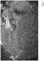
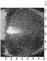
- the lenses of vehicle cameras, consumer digital cameras, or the front windows of security cameras often accumulate various types of contaminants over time such as water, fingerprints, dust and dirt. Artifacts from a dirty camera are shown in Figs. 1 and 2 .
- a method that detects that there are issues on the lens can order the lens to be cleaned, notify a human that it needs attention or disable or notify the methods that follow that that particular part of the image is not usable.
- the media obstructing the visual path is located at the lens, it either obstructs light completely, as shown in Fig. 1 , or it makes the information very blurry in the soiled regions.
- the latter occurs because the media is not in focus and also because elements like water droplets have a magnifying effect, as shown in Fig. 2 .
- An approach which detects blurred regions works best if the entire image or very large portions of it are being considered, since it is very unlikely that an image taken from a realistic environment is blurred everywhere.
- this ambiguity can be reduced or even resolved.
- areas with sharp edges can be marked as artifact free. This step is based on the consideration that a sharp edge on the image indicates that the lens is not soiled in that location.
- a known movement of the vehicle is used to derive a trajectory of an edge point and to check if the edge point is observed at an expected location of the image. If an edge point is not detected at some location along its expected trajectory, the location corresponds to a location of the lens that is soiled and is marked as an artifact.
- the magnitude of derivatives, E, in the image, I is computed for every frame.
- the derivative E can be obtained by a convolution with a filter that approximates a derivative.
- Absolute maximum and minimum values of the second derivative have been found particularly useful for edge detection.
- the sum of the second derivatives in all spatial directions is also referred to as a "Laplace operator".
- This approximation is isotropic, i.e., puts equal weight on vertical, horizontal and diagonal derivatives.
- the pixel values I(x, y) represent an intensity, such as a grey scale intensity, an intensity in a colour channel or also an effective intensity of multiple colour channels.
- Laplace filter instead of a Laplace filter, other derivative operators such as the Sobel or Prewitt derivative operators can be used to identify changes within the images.
- the values along the borders of the image frame can be computed by imposing special conditions, for example by creating an outer frame, wherein the pixels have the same or similar values as the outer pixels or zero values.
- the convolution is only computed for the inner pixels of the image frame.
- the detection threshold ThEdge is chosen sufficiently high, such that only the clearly visible transitions are detected.
- a lower resolution version of T HRes is computed, wherein each pixel corresponds to non-overlapping N ⁇ N pixels of the original resolution.
- N x N can be chosen as 20 x 20 pixels.
- the low resolution probability is assigned to all pixels of the subregion.
- the pixels of the subregion correspond to an effective "N x N pixel" (x0, y0), which is stored as a single low-resolution pixel in computer memory.
- a 1280 x 800 image frame can be divided into non-overlapping or disjoint quadratic subregions with sizes 10 x 10, 16 x 16, 20 x 20 or 40 x 40.
- regions ⁇ ( x 0 , y 0 ) with different sizes may be the case if an image frame cannot be subdivided into N x N regions without remainder.
- the subregions may also comprise rectangular subregions, in particular near the boundary of the image frame.
- the probabilities of detecting a transition for a few frames is stored in a computer memory.
- a method of determining the number of frames to be stored is described further below.
- conditional probability that the lens is clean in a point (x,y) along the trajectory of a transition point is represented as the conditional probability of finding a transition in that trajectory in a nearby frame with a frame index f ⁇ , under the condition that a transition was detected at point ( x 0 , y 0 ).
- the right hand side refers to the probability that there exists at least one frame, with index in [f+1, f+F], such that it has a transition T(x, y) for this frame index, under the condition that the transition in point (x 0 , y 0 ) has value T(x 0 , y 0 ), and under the condition that (x, y) is a point on an estimated transition point trajectory starting in (x 0 , y 0 ).
- the transition values T can have any value between 0 and 1.
- C f ( x,y ) is computed for frames in which the vehicle is moving in an approximate straight line.
- the trajectory estimation is made simpler.
- the motion of the vehicle can be determined by using CAN data and the vehicle speed. This situation occurs most of the times and will in general lead to a valid approximation. However, all other motions are also possible.
- Fig. 4 illustrates an estimated three-dimensional surface and vectors obtained from it.
- the scenario of Fig. 4 is such that the image processing system estimates a forward motion.
- Fig. 4 shows that some vectors are approximately zero. Since no trajectory is created in these regions, it is not possible to estimate soiling of the lens there. However, they occur mostly in sky regions when the vehicle has forward motion and, therefore, are not so important. To determine soiling in all areas of the lens, other types of motion, such as curving to the left or right, are needed.
- the scene is subdivided into a first region, which corresponds to the ground surface, a second region, which is left to a fixed point of the motion and a right region, which is right the fixed point.
- the objects are assumed to have vertical orientation.
- An artifact detection according to the present specification is improved when the overall probability C (x,y) of the lens being clean is obtained over time and with a lot of accumulated evidence.
- a transition request be the expectation that is created in point ( x,y ) from the fact that a transition was detected in point ( x 0 , y 0 ) in a nearby frame.
- C ( x,y ) can be computed as the ratio between the number of transition requests that are satisfied, Sat ( x,y ), and the total amount of transition requests, Tot ( x,y ), for that pixel.
- Tot ( x,y ) and Sat ( x,y ) are probabilities and may also be regarded as relative numbers of transition requests.
- the value of Tot ( x,y ) provides a measure of confidence for the value of C ( x,y ).
- Smaller values of Tot ( x,y ) indicate that few transitions were expected in that pixel and that a large importance is being given to the few observations that were made.
- Larger values of Tot ( x,y ) imply that C ( x,y ) is the result of a large set of accumulated data and, therefore, has a higher probability of being correct. This is in turn indicates a higher probability that the value is not affected by the abovementioned simplifying assumptions.
- the number of frames F to use and store are the result of a compromise.
- F should be as large as possible, to enable the detection of very large blurry areas: the more frames F are used, the longer is the expected trajectory and deeper it can go into blurry areas.
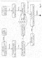
- Fig. 4 illustrates a method for detection of a lens contamination according to the present specification.
- image frames of size 1280 x 800 pixels are received from a vehicle camera, which operates at a frame rate of 30 frames per second.
- a magnitude of a derivative is computed for the pixels of the image frames by computing the two-dimensional convolution of a filter that approximates a Laplacian operator.
- a transition probability is computed as the minimum of the derivative magnitude divided by a transition threshold "Th" and the value 1.
- the transition probability can also be regarded as the probability that the pixel corresponds to a feature point, such as an edge.
- a fourth step 24 the image frame is subdivided into disjunct 20 x 20 subregions and a low resolution transition probability of a 20 x 20 subregion is computed as the maximum of the previously computed transition probabilities over the respective 20 x 20 subregion.
- the low resolution probability is assigned to an effective pixel.
- a fifth step 25 pixels having a low resolution probability of 1 are marked as clear.
- the set of low resolution transition values for F + 1 consecutive image frames, which has been computed in the previous step 24 is stored in a circular buffer.
- a seventh step 27 the vehicle speed and steering angle are received from a CAN bus and in an eight step 28, estimated motion vectors are computed using the vehicle speed and steering angle of step 27 and a simplified model of the exterior scene.
- the motion vectors are computed for regions of the scene, which are assumed to be non-moving and to have horizontal or vertical orientation.
- the road surface and artificial structures along the road side provide corresponding objects.
- a ninth step 29 the low resolution transition values of the F + 1 image frames in the circular buffer are used to find transitions along the estimated trajectories and to compare detected and expected transitions.
- the ratios of detected and expected transitions are accumulated, wherein the regions, which have already been marked as clean in the fifth step, are taken into account.
- the ratios are used in an eleventh step 31 to create a "cleanMap" which indicates locations of the lens which are clean, soiled or for which a contamination status cannot be derived with a sufficient certainty.
- the cleanMap can be represented by a memory area of a computer memory, which represents values that indicate which pixels correspond to clean areas of the lens and which pixels correspond to contaminated areas of the lens.
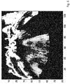
- the image series of Figures 5 to 7 shows the results of the artifact detection method after processing 10 frames of a sequence of the front camera using a surround view system, in which the lenses have drops of water.
- the second image, Fig. 6 shows the requests that were detected at those pixels, with brighter regions being originated mostly by strong transitions, since they have a high impact on this map.
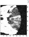
- the third image, Fig. 7 shows an estimate of the state of the lens.
- the white pixels mean that there isn't enough data to confirm any scenario, which is equivalent to Tot ( x,y ) ⁇ 0.95 for the threshold of Fig. 7 .
- the grey pixels indicate that the lens is clean at those pixels.
- the image series of Figures 8 to 10 , 11 to 13 and 14 to 16 show the evolution of the estimates, as more measurements are collected.
- the second images, Figs. 9 , 12 and 15 indicate that the amount of data that was expected for each pixel becomes progressively complete.
- the third images, Figs. 10 , 13 and 16 converge towards the estimate of the state of the lens.
- Figs. 5 to 16 demonstrate the effectiveness of a method in capturing the soiling status of the lens, both in locations that are densely populated with transitions and on locations that are not. Naturally, areas with little content take longer to detect.
- transitions are detected but not tracked.
- the method results to be simple, yet powerful.
- a "tracking" comprises an explicit search or comparison to find out where a feature went on the subsequent frames.
- the method according to the first embodiment is based on the assumption that the transitions will be detected somewhere along the expected trajectory. It does not require a confirmation that a transition at a point (x, y) actually corresponds to the transition that was detected at point (x0, y0). It could actually be a transition from some other point (x1, y1).
- the accuracy of the method can be increased by tracking the detected transition with a matching method such as sum absolute difference (SAD), correlation, sum squared difference (SSD) or a scale invariant feature transform (SIFT).
- a matching method such as sum absolute difference (SAD), correlation, sum squared difference (SSD) or a scale invariant feature transform (SIFT).
Landscapes
- Engineering & Computer Science (AREA)
- Computer Vision & Pattern Recognition (AREA)
- Physics & Mathematics (AREA)
- General Physics & Mathematics (AREA)
- Theoretical Computer Science (AREA)
- Quality & Reliability (AREA)
- Multimedia (AREA)
- Image Analysis (AREA)
- Studio Devices (AREA)
Claims (15)
- Verfahren zum Detektieren von Verschmutzungen auf einer Linse einer Fahrzeugkamera, das Folgendes umfasst:- Empfangen von Bilddaten von der Fahrzeugkamera, wobei die Bilddaten Bildrahmen umfassen,- Zuweisen von Übergangswerten, die angeben, ob an einem entsprechenden Bildpunktort des Rahmens ein eindeutig erkennbarer Intensitätsübergang von dunkel zu hell oder von hell zu dunkel vorliegt, zu Bildpunkten der Bildrahmen,- Zuweisen von dreidimensionalen Koordinaten zu den Bildpunkten unter Verwendung eines Modells der äußeren Landschaft,- Verwenden der zugewiesenen, dreidimensionalen Koordinaten und von Bewegungsdaten des Fahrzeugs, um den Bildpunkten Bewegungsbahnen zuzuweisen, wobei die Bewegungsdaten durch einen oder mehrere Fahrzeugsensoren bereitgestellt werden, wobei eine Bewegungsbahn Bildpunkte aus einer Gruppe benachbarter Bildrahmen umfasst, wobei sich die Bewegungsbahn für jene Bildpunkte, denen eine Bewegungsbahn zugewiesen ist, zeitlich vorwärts oder rückwärts erstrecken kann,- Berechnen eines Erwartungswertes für den Bildpunkt, wobei der Erwartungswert von einem Übergangswert eines Anfangsbildpunktes der Bewegungsbahn abgeleitet wird,- Berechnen eines erfüllten Übergangswertes für den Bildpunktort, wobei der erfüllte Übergangswert von Übergangswerten entlang der Bewegungsbahn für eine Gruppe von Rahmen, die an den Rahmen des Anfangsbildpunktes angrenzen, abgeleitet wird,- Akkumulieren des Erwartungswertes und des erfüllten Übergangswertes im Zeitablauf,- Ableiten eines Sauberkeitswertes von einem Verhältnis des akkumulierten, erfüllten Übergangswertes zu dem akkumulierten Erwartungswert.
- Computerprogrammprodukt, auf dem computerausführbarer Code gespeichert ist, der dann, wenn er auf einem Computer ausgeführt wird, das Verfahren nach Anspruch 1 ausführt.
- Auswertungseinheit, wobei die Auswertungseinheit Folgendes umfasst:- eine Eingangsverbindung zum Empfangen von Bilddaten,- einen Puffer zum Speichern einer vorgegebenen Anzahl von Bildrahmen, wobei die Auswertungseinheit betreibbar ist zum- Empfangen von Bilddaten von der Fahrzeugkamera über die Eingangsverbindung, wobei die Bilddaten Bildrahmen umfassen,- Zuweisen von Übergangswerten, die angeben, ob an einem entsprechenden Bildpunktort des Rahmens ein eindeutig erkennbarer Intensitätsübergang von dunkel zu hell oder von hell zu dunkel vorliegt, zu Bildpunkten der Bildrahmen,- Zuweisen von dreidimensionalen Koordinaten zu den Bildpunkten unter Verwendung eines Modells der äußeren Landschaft,- Verwenden der zugewiesenen, dreidimensionalen Koordinaten und von Bewegungsdaten des Fahrzeugs, um den Bildpunkten Bewegungsbahnen zuzuweisen, wobei die Bewegungsdaten durch einen oder mehrere Fahrzeugsensoren bereitgestellt werden, wobei eine Bewegungsbahn Bildpunkte aus einer Gruppe benachbarter Bildrahmen umfasst, wobei sich die Bewegungsbahn für jene Bildpunkte, denen eine Bewegungsbahn zugewiesen ist, zeitlich vorwärts oder rückwärts erstrecken kann,- Berechnen eines Erwartungswertes für den Bildpunkt, wobei der Erwartungswert von einem Übergangswert eines Anfangsbildpunktes der Bewegungsbahn abgeleitet wird,- Berechnen eines erfüllten Übergangswertes für den Bildpunktort, wobei der erfüllte Übergangswert von Übergangswerten entlang der Bewegungsbahn für eine Gruppe von Rahmen in dem Puffer, die an den Rahmen des Anfangsbildpunktes angrenzen, abgeleitet wird,- Akkumulieren des Erwartungswertes und des erfüllten Übergangswertes im Zeitablauf,- Ableiten eines Sauberkeitswertes von einem Verhältnis des akkumulierten, erfüllten Übergangswertes zu dem akkumulierten Erwartungswert.
- Auswertungseinheit nach Anspruch 3, wobei der Puffer zum Speichern der Bildrahmen ein Rundpuffer ist.
- Auswertungseinheit nach Anspruch 3 oder 4, die ferner einen ersten Speicherbereich zum Speichern einer Gruppe akkumulierter Erwartungswerte und einen zweiten Speicherbereich zum Speichern einer Gruppe erfüllter Übergangswerte umfasst, wobei ein Element der jeweiligen Gruppe einem Bildpunktort entspricht.
- Auswertungseinheit nach einem der Ansprüche 3 bis 5, wobei die Auswertungseinheit betreibbar ist zum- Vergleichen des akkumulierten Erwartungswertes mit einem vorgegebenen Schwellenwert,
Einstellen des Sauberkeitswertes des Bildpunktes auf das Verhältnis des akkumulierten, erfüllten Übergangswertes zu dem akkumulierten Erwartungswert, wenn der Erwartungswert größer als der vorgegebene Schwellenwert ist,
und zum Darstellen des Sauberkeitswertes des Bildpunktes als "unbestimmt", wenn der Erwartungswert kleiner als der vorgegebene Schwellenwert ist. - Auswertungseinheit nach einem der Ansprüche 3 bis 6, wobei die Auswertungseinheit betreibbar ist zum Berechnen der Übergangswerte als eine zweidimensionale Faltung eines Filters mit Bildpunkten eines Bildrahmenbildpunktes.
- Auswertungseinheit nach einem der Ansprüche 3 bis 7, wobei die Auswertungseinheit betreibbar ist zum Vergleichen der Bildpunktübergangswerte mit einem Detektionsschwellenwert und Einstellen des jeweiligen Übergangswertes auf eins, wenn der jeweilige Übergangswert größer oder gleich dem Detektionsschwellenwert ist.
- Auswertungseinheit nach einem der Ansprüche 3 bis 8, wobei die Auswertungseinheit betreibbar ist zum- Aufteilen der Bildrahmen in getrennte Teilbereiche und Berechnen von Niedrigauflösungs-Übergangswerten durch Auswählen von Maximalwerten der Übergangswerte in den Teilbereichen,- Speichern der Niedrigauflösungs-Übergangswerte in dem Puffer für eine vorgegebene Anzahl von Bildrahmen,- Verwenden der Niedrigauflösungs-Übergangswerte, um die entsprechenden Erwartungswerte und die entsprechenden erfüllten Übergangswerte zu berechnen.
- Auswertungseinheit nach einem der Ansprüche 3 bis 9, wobei die Auswertungseinheit betreibbar ist zum Empfangen und Verarbeiten von Bewegungsdaten von einem Fahrzeuggeschwindigkeitssensor und von einem Lenkwinkelsensor.
- Auswertungseinheit nach einem der Ansprüche 3 bis 10, wobei die Auswertungseinheit betreibbar ist zum Empfangen und Verarbeiten von Bewegungsdaten von mindestens einem Kamerasensor.
- Auswertungseinheit nach einem der Ansprüche 3 bis 11, wobei die Auswertungseinheit betreibbar ist zum Zuweisen von Bewegungsvektoren zu den Bildpunkten der Bildrahmen gemäß einem vereinfachten Modell einer umgebenden Landschaft, wobei das vereinfachte Modell eine horizontale Bodenoberfläche, einen ersten Bereich vertikaler Gegenstände und einen zweiten Bereich vertikaler Gegenstände umfasst.
- Auswertungseinheit nach einem der Ansprüche 3 bis 11, wobei die Auswertungseinheit betreibbar ist zum Identifizieren von Bildrahmen, für die sich das Fahrzeug im Wesentlichen in einer geraden Linie bewegt, und zum Aktualisieren des Erwartungswertes und des erfüllten Übergangswertes für die identifizierten Rahmen.
- Bausatz, wobei der Bausatz die Auswertungseinheit nach Anspruch 13 und mindestens eine Fahrzeugkamera umfasst, wobei die Fahrzeugkamera mit der Auswertungseinheit verbunden werden kann.
- Fahrzeug, das den Bausatz nach Anspruch 14 umfasst, wobei die Auswertungseinheit mit einem Kraftfahrzeugdatenbus des Fahrzeugs verbunden ist, die mindestens eine Kamera an dem Fahrzeug angebracht ist und die mindestens eine Kamera mit der Auswertungseinheit verbunden ist.
Priority Applications (4)
| Application Number | Priority Date | Filing Date | Title |
|---|---|---|---|
| EP15174937.1A EP3113108B1 (de) | 2015-07-02 | 2015-07-02 | Erkennung von linsenkontamination mit erwarteten kantentrajektorien |
| PCT/EP2016/063650 WO2017001189A1 (en) | 2015-07-02 | 2016-06-14 | Detection of lens contamination using expected edge trajectories |
| JP2017567406A JP6744336B2 (ja) | 2015-07-02 | 2016-06-14 | 予想されるエッジ軌跡を用いたレンズ汚染の検出 |
| US15/834,601 US10388008B2 (en) | 2015-07-02 | 2017-12-07 | Detection of lens contamination using expected edge trajectories |
Applications Claiming Priority (1)
| Application Number | Priority Date | Filing Date | Title |
|---|---|---|---|
| EP15174937.1A EP3113108B1 (de) | 2015-07-02 | 2015-07-02 | Erkennung von linsenkontamination mit erwarteten kantentrajektorien |
Publications (2)
| Publication Number | Publication Date |
|---|---|
| EP3113108A1 EP3113108A1 (de) | 2017-01-04 |
| EP3113108B1 true EP3113108B1 (de) | 2020-03-11 |
Family
ID=53723991
Family Applications (1)
| Application Number | Title | Priority Date | Filing Date |
|---|---|---|---|
| EP15174937.1A Active EP3113108B1 (de) | 2015-07-02 | 2015-07-02 | Erkennung von linsenkontamination mit erwarteten kantentrajektorien |
Country Status (4)
| Country | Link |
|---|---|
| US (1) | US10388008B2 (de) |
| EP (1) | EP3113108B1 (de) |
| JP (1) | JP6744336B2 (de) |
| WO (1) | WO2017001189A1 (de) |
Families Citing this family (17)
| Publication number | Priority date | Publication date | Assignee | Title |
|---|---|---|---|---|
| JP6690955B2 (ja) * | 2016-02-02 | 2020-04-28 | 株式会社デンソーテン | 画像処理装置及び水滴除去システム |
| US10196047B1 (en) * | 2017-08-07 | 2019-02-05 | Ford Global Technologies, Llc | Contamination prevention of vehicle cameras and sensors |
| EP3489892B1 (de) * | 2017-11-24 | 2022-01-05 | Ficosa Adas, S.L.U. | Bestimmung von sauberen oder schmutzigen aufgenommenen bildern |
| US11479213B1 (en) * | 2017-12-11 | 2022-10-25 | Zoox, Inc. | Sensor obstruction detection and mitigation |
| US10549723B2 (en) * | 2018-05-04 | 2020-02-04 | Ford Global Technologies, Llc | Vehicle object-detection sensor assembly |
| JP2020005142A (ja) * | 2018-06-28 | 2020-01-09 | キヤノン株式会社 | 撮像装置及びその制御方法、プログラム、記憶媒体 |
| CN111583169A (zh) * | 2019-01-30 | 2020-08-25 | 杭州海康威视数字技术股份有限公司 | 一种车载相机镜头的污染处理方法及系统 |
| US11209282B2 (en) * | 2019-07-02 | 2021-12-28 | Ford Global Technologies, Llc | Vehicle cleanliness detection and carwash recommendation |
| US11328428B2 (en) * | 2019-12-18 | 2022-05-10 | Clarion Co., Ltd. | Technologies for detection of occlusions on a camera |
| KR20210128803A (ko) | 2020-04-17 | 2021-10-27 | 삼성전자주식회사 | 다중 포토다이오드 센서에 의해 획득된 서브 이미지들의 차이에 기반하여 이미지의 결함을 검출하는 전자 장치 및 이의 동작 방법 |
| DE102020112204A1 (de) | 2020-05-06 | 2021-11-11 | Connaught Electronics Ltd. | System und Verfahren zum Steuern einer Kamera |
| JP7319597B2 (ja) * | 2020-09-23 | 2023-08-02 | トヨタ自動車株式会社 | 車両運転支援装置 |
| WO2022092620A1 (en) | 2020-10-30 | 2022-05-05 | Samsung Electronics Co., Ltd. | Method and system operating an imaging system in an image capturing device based on artificial intelligence techniques |
| US11102381B1 (en) | 2021-01-05 | 2021-08-24 | Board Of Regents, The University Of Texas System Clearcam Inc. | Methods, systems and controllers for facilitating cleaning of an imaging element of an imaging device |
| SE2150168A1 (en) * | 2021-02-16 | 2022-08-17 | Husqvarna Ab | Robotic work tool system and method for determining whether there is an interfering object on a camera unit of a robotic work tool |
| CN114757888B (zh) * | 2022-03-21 | 2025-03-21 | 同济大学 | 一种基于纹理特征的挡风玻璃脏污检测方法 |
| US12470835B2 (en) * | 2023-02-06 | 2025-11-11 | Motorola Solutions, Inc. | Method and apparatus for analyzing a dirty camera lens to determine if the dirty camera lens causes a failure to detect various events |
Family Cites Families (9)
| Publication number | Priority date | Publication date | Assignee | Title |
|---|---|---|---|---|
| JP2008060874A (ja) * | 2006-08-31 | 2008-03-13 | Hitachi Ltd | 車載カメラ及び車載カメラ用付着物検出装置 |
| WO2010038223A1 (en) | 2008-10-01 | 2010-04-08 | Hi-Key Limited | A method and a system for detecting the presence of an impediment on a lens of an image capture device to light passing through the lens of an image capture device |
| JP2010273014A (ja) * | 2009-05-20 | 2010-12-02 | Toshiba Alpine Automotive Technology Corp | 移動体用カメラ装置及び付着物検出方法 |
| US9616851B2 (en) * | 2011-06-17 | 2017-04-11 | Robert Bosch Gmbh | Method and apparatus for recognizing directional structures on a window pane of a vehicle |
| JP2014011785A (ja) * | 2012-07-03 | 2014-01-20 | Clarion Co Ltd | 車載カメラ汚れ除去装置の診断装置、診断方法及び車両システム |
| JP6117634B2 (ja) * | 2012-07-03 | 2017-04-19 | クラリオン株式会社 | レンズ付着物検知装置、レンズ付着物検知方法、および、車両システム |
| JP5981322B2 (ja) * | 2012-11-27 | 2016-08-31 | クラリオン株式会社 | 車載画像処理装置 |
| US9767571B2 (en) * | 2013-07-29 | 2017-09-19 | Samsung Electronics Co., Ltd. | Apparatus and method for analyzing image including event information |
| JP6174975B2 (ja) * | 2013-11-14 | 2017-08-02 | クラリオン株式会社 | 周囲環境認識装置 |
-
2015
- 2015-07-02 EP EP15174937.1A patent/EP3113108B1/de active Active
-
2016
- 2016-06-14 JP JP2017567406A patent/JP6744336B2/ja active Active
- 2016-06-14 WO PCT/EP2016/063650 patent/WO2017001189A1/en not_active Ceased
-
2017
- 2017-12-07 US US15/834,601 patent/US10388008B2/en active Active
Non-Patent Citations (1)
| Title |
|---|
| None * |
Also Published As
| Publication number | Publication date |
|---|---|
| EP3113108A1 (de) | 2017-01-04 |
| WO2017001189A1 (en) | 2017-01-05 |
| JP2018523223A (ja) | 2018-08-16 |
| JP6744336B2 (ja) | 2020-08-19 |
| US10388008B2 (en) | 2019-08-20 |
| US20180096474A1 (en) | 2018-04-05 |
Similar Documents
| Publication | Publication Date | Title |
|---|---|---|
| US10388008B2 (en) | Detection of lens contamination using expected edge trajectories | |
| You et al. | Adherent raindrop modeling, detection and removal in video | |
| US11138698B2 (en) | Static soiling detection and correction | |
| You et al. | Adherent raindrop detection and removal in video | |
| CN107038723B (zh) | 棒状像素估计方法和系统 | |
| CN111860120B (zh) | 车载相机自动遮挡检测方法和装置 | |
| Roser et al. | Realistic modeling of water droplets for monocular adherent raindrop recognition using bezier curves | |
| EP3070430B1 (de) | Vorrichtung zur positionsschätzung eines beweglichen körpers und verfahren zur positionsschätzung eines beweglichen körpers | |
| JP7107931B2 (ja) | 移動オブジェクトのレンジを推定する方法および装置 | |
| CN116648734A (zh) | 下雨、光线入射和脏污时环视摄像系统图像的修正 | |
| CN113689493A (zh) | 镜头附着物检测方法、装置、电子设备和存储介质 | |
| WO2013107525A1 (en) | Impact time from image sensing | |
| JP2013122624A (ja) | 車両火災検出装置 | |
| US12299906B2 (en) | Estimating the movement of an image position | |
| KR20190007758A (ko) | 영상 처리 시스템 및 그에 의한 영상 처리 방법 | |
| Tanaka et al. | Removal of adherent waterdrops from images acquired with a stereo camera system | |
| US9928430B2 (en) | Dynamic stixel estimation using a single moving camera | |
| Chumerin et al. | Ground plane estimation based on dense stereo disparity | |
| EP3306522A1 (de) | Vorrichtung zur bestimmung eines interessierenden bereiches auf und/oder in einer fahrzeugscheibe | |
| JP7169227B2 (ja) | 異常検出装置、および異常検出方法 | |
| CN115272781A (zh) | 车辆图像的评价方法及其设备 | |
| EP3282420B1 (de) | Verfahren und vorrichtung zur verschmutzungsdetektion, bildverarbeitungssystem und fortschrittliches fahrerassistenzsystem | |
| KR101728670B1 (ko) | 카메라 이물질 부착 확인 기능을 구비한 avm 시스템 및 카메라 이물질 부착 확인 방법 | |
| CN115880239B (zh) | 相机视野干扰的检测方法、装置、智能机器人及存储介质 | |
| WO2007072370A2 (en) | Method and apparatus for estimating object speed |
Legal Events
| Date | Code | Title | Description |
|---|---|---|---|
| PUAI | Public reference made under article 153(3) epc to a published international application that has entered the european phase |
Free format text: ORIGINAL CODE: 0009012 |
|
| STAA | Information on the status of an ep patent application or granted ep patent |
Free format text: STATUS: THE APPLICATION HAS BEEN PUBLISHED |
|
| AK | Designated contracting states |
Kind code of ref document: A1 Designated state(s): AL AT BE BG CH CY CZ DE DK EE ES FI FR GB GR HR HU IE IS IT LI LT LU LV MC MK MT NL NO PL PT RO RS SE SI SK SM TR |
|
| AX | Request for extension of the european patent |
Extension state: BA ME |
|
| STAA | Information on the status of an ep patent application or granted ep patent |
Free format text: STATUS: REQUEST FOR EXAMINATION WAS MADE |
|
| 17P | Request for examination filed |
Effective date: 20170704 |
|
| RBV | Designated contracting states (corrected) |
Designated state(s): AL AT BE BG CH CY CZ DE DK EE ES FI FR GB GR HR HU IE IS IT LI LT LU LV MC MK MT NL NO PL PT RO RS SE SI SK SM TR |
|
| GRAP | Despatch of communication of intention to grant a patent |
Free format text: ORIGINAL CODE: EPIDOSNIGR1 |
|
| STAA | Information on the status of an ep patent application or granted ep patent |
Free format text: STATUS: GRANT OF PATENT IS INTENDED |
|
| INTG | Intention to grant announced |
Effective date: 20191105 |
|
| GRAS | Grant fee paid |
Free format text: ORIGINAL CODE: EPIDOSNIGR3 |
|
| GRAA | (expected) grant |
Free format text: ORIGINAL CODE: 0009210 |
|
| STAA | Information on the status of an ep patent application or granted ep patent |
Free format text: STATUS: THE PATENT HAS BEEN GRANTED |
|
| AK | Designated contracting states |
Kind code of ref document: B1 Designated state(s): AL AT BE BG CH CY CZ DE DK EE ES FI FR GB GR HR HU IE IS IT LI LT LU LV MC MK MT NL NO PL PT RO RS SE SI SK SM TR |
|
| REG | Reference to a national code |
Ref country code: GB Ref legal event code: FG4D |
|
| REG | Reference to a national code |
Ref country code: CH Ref legal event code: EP |
|
| REG | Reference to a national code |
Ref country code: AT Ref legal event code: REF Ref document number: 1244076 Country of ref document: AT Kind code of ref document: T Effective date: 20200315 |
|
| REG | Reference to a national code |
Ref country code: DE Ref legal event code: R096 Ref document number: 602015048460 Country of ref document: DE |
|
| REG | Reference to a national code |
Ref country code: IE Ref legal event code: FG4D |
|
| REG | Reference to a national code |
Ref country code: SE Ref legal event code: TRGR |
|
| PG25 | Lapsed in a contracting state [announced via postgrant information from national office to epo] |
Ref country code: NO Free format text: LAPSE BECAUSE OF FAILURE TO SUBMIT A TRANSLATION OF THE DESCRIPTION OR TO PAY THE FEE WITHIN THE PRESCRIBED TIME-LIMIT Effective date: 20200611 Ref country code: FI Free format text: LAPSE BECAUSE OF FAILURE TO SUBMIT A TRANSLATION OF THE DESCRIPTION OR TO PAY THE FEE WITHIN THE PRESCRIBED TIME-LIMIT Effective date: 20200311 Ref country code: RS Free format text: LAPSE BECAUSE OF FAILURE TO SUBMIT A TRANSLATION OF THE DESCRIPTION OR TO PAY THE FEE WITHIN THE PRESCRIBED TIME-LIMIT Effective date: 20200311 |
|
| REG | Reference to a national code |
Ref country code: NL Ref legal event code: MP Effective date: 20200311 |
|
| RAP2 | Party data changed (patent owner data changed or rights of a patent transferred) |
Owner name: CONTINENTAL AUTOMOTIVE GMBH |
|
| PG25 | Lapsed in a contracting state [announced via postgrant information from national office to epo] |
Ref country code: BG Free format text: LAPSE BECAUSE OF FAILURE TO SUBMIT A TRANSLATION OF THE DESCRIPTION OR TO PAY THE FEE WITHIN THE PRESCRIBED TIME-LIMIT Effective date: 20200611 Ref country code: LV Free format text: LAPSE BECAUSE OF FAILURE TO SUBMIT A TRANSLATION OF THE DESCRIPTION OR TO PAY THE FEE WITHIN THE PRESCRIBED TIME-LIMIT Effective date: 20200311 Ref country code: HR Free format text: LAPSE BECAUSE OF FAILURE TO SUBMIT A TRANSLATION OF THE DESCRIPTION OR TO PAY THE FEE WITHIN THE PRESCRIBED TIME-LIMIT Effective date: 20200311 Ref country code: GR Free format text: LAPSE BECAUSE OF FAILURE TO SUBMIT A TRANSLATION OF THE DESCRIPTION OR TO PAY THE FEE WITHIN THE PRESCRIBED TIME-LIMIT Effective date: 20200612 |
|
| REG | Reference to a national code |
Ref country code: LT Ref legal event code: MG4D |
|
| PG25 | Lapsed in a contracting state [announced via postgrant information from national office to epo] |
Ref country code: NL Free format text: LAPSE BECAUSE OF FAILURE TO SUBMIT A TRANSLATION OF THE DESCRIPTION OR TO PAY THE FEE WITHIN THE PRESCRIBED TIME-LIMIT Effective date: 20200311 |
|
| PG25 | Lapsed in a contracting state [announced via postgrant information from national office to epo] |
Ref country code: PT Free format text: LAPSE BECAUSE OF FAILURE TO SUBMIT A TRANSLATION OF THE DESCRIPTION OR TO PAY THE FEE WITHIN THE PRESCRIBED TIME-LIMIT Effective date: 20200805 Ref country code: RO Free format text: LAPSE BECAUSE OF FAILURE TO SUBMIT A TRANSLATION OF THE DESCRIPTION OR TO PAY THE FEE WITHIN THE PRESCRIBED TIME-LIMIT Effective date: 20200311 Ref country code: CZ Free format text: LAPSE BECAUSE OF FAILURE TO SUBMIT A TRANSLATION OF THE DESCRIPTION OR TO PAY THE FEE WITHIN THE PRESCRIBED TIME-LIMIT Effective date: 20200311 Ref country code: LT Free format text: LAPSE BECAUSE OF FAILURE TO SUBMIT A TRANSLATION OF THE DESCRIPTION OR TO PAY THE FEE WITHIN THE PRESCRIBED TIME-LIMIT Effective date: 20200311 Ref country code: SM Free format text: LAPSE BECAUSE OF FAILURE TO SUBMIT A TRANSLATION OF THE DESCRIPTION OR TO PAY THE FEE WITHIN THE PRESCRIBED TIME-LIMIT Effective date: 20200311 Ref country code: EE Free format text: LAPSE BECAUSE OF FAILURE TO SUBMIT A TRANSLATION OF THE DESCRIPTION OR TO PAY THE FEE WITHIN THE PRESCRIBED TIME-LIMIT Effective date: 20200311 Ref country code: SK Free format text: LAPSE BECAUSE OF FAILURE TO SUBMIT A TRANSLATION OF THE DESCRIPTION OR TO PAY THE FEE WITHIN THE PRESCRIBED TIME-LIMIT Effective date: 20200311 Ref country code: IS Free format text: LAPSE BECAUSE OF FAILURE TO SUBMIT A TRANSLATION OF THE DESCRIPTION OR TO PAY THE FEE WITHIN THE PRESCRIBED TIME-LIMIT Effective date: 20200711 |
|
| REG | Reference to a national code |
Ref country code: AT Ref legal event code: MK05 Ref document number: 1244076 Country of ref document: AT Kind code of ref document: T Effective date: 20200311 |
|
| REG | Reference to a national code |
Ref country code: DE Ref legal event code: R097 Ref document number: 602015048460 Country of ref document: DE |
|
| PLBE | No opposition filed within time limit |
Free format text: ORIGINAL CODE: 0009261 |
|
| STAA | Information on the status of an ep patent application or granted ep patent |
Free format text: STATUS: NO OPPOSITION FILED WITHIN TIME LIMIT |
|
| PG25 | Lapsed in a contracting state [announced via postgrant information from national office to epo] |
Ref country code: ES Free format text: LAPSE BECAUSE OF FAILURE TO SUBMIT A TRANSLATION OF THE DESCRIPTION OR TO PAY THE FEE WITHIN THE PRESCRIBED TIME-LIMIT Effective date: 20200311 Ref country code: AT Free format text: LAPSE BECAUSE OF FAILURE TO SUBMIT A TRANSLATION OF THE DESCRIPTION OR TO PAY THE FEE WITHIN THE PRESCRIBED TIME-LIMIT Effective date: 20200311 Ref country code: DK Free format text: LAPSE BECAUSE OF FAILURE TO SUBMIT A TRANSLATION OF THE DESCRIPTION OR TO PAY THE FEE WITHIN THE PRESCRIBED TIME-LIMIT Effective date: 20200311 |
|
| 26N | No opposition filed |
Effective date: 20201214 |
|
| PG25 | Lapsed in a contracting state [announced via postgrant information from national office to epo] |
Ref country code: PL Free format text: LAPSE BECAUSE OF FAILURE TO SUBMIT A TRANSLATION OF THE DESCRIPTION OR TO PAY THE FEE WITHIN THE PRESCRIBED TIME-LIMIT Effective date: 20200311 Ref country code: SI Free format text: LAPSE BECAUSE OF FAILURE TO SUBMIT A TRANSLATION OF THE DESCRIPTION OR TO PAY THE FEE WITHIN THE PRESCRIBED TIME-LIMIT Effective date: 20200311 Ref country code: MC Free format text: LAPSE BECAUSE OF FAILURE TO SUBMIT A TRANSLATION OF THE DESCRIPTION OR TO PAY THE FEE WITHIN THE PRESCRIBED TIME-LIMIT Effective date: 20200311 |
|
| REG | Reference to a national code |
Ref country code: CH Ref legal event code: PL |
|
| REG | Reference to a national code |
Ref country code: BE Ref legal event code: MM Effective date: 20200731 |
|
| PG25 | Lapsed in a contracting state [announced via postgrant information from national office to epo] |
Ref country code: IE Free format text: LAPSE BECAUSE OF NON-PAYMENT OF DUE FEES Effective date: 20200702 Ref country code: LI Free format text: LAPSE BECAUSE OF NON-PAYMENT OF DUE FEES Effective date: 20200731 Ref country code: LU Free format text: LAPSE BECAUSE OF NON-PAYMENT OF DUE FEES Effective date: 20200702 Ref country code: CH Free format text: LAPSE BECAUSE OF NON-PAYMENT OF DUE FEES Effective date: 20200731 |
|
| PG25 | Lapsed in a contracting state [announced via postgrant information from national office to epo] |
Ref country code: BE Free format text: LAPSE BECAUSE OF NON-PAYMENT OF DUE FEES Effective date: 20200731 |
|
| PG25 | Lapsed in a contracting state [announced via postgrant information from national office to epo] |
Ref country code: TR Free format text: LAPSE BECAUSE OF FAILURE TO SUBMIT A TRANSLATION OF THE DESCRIPTION OR TO PAY THE FEE WITHIN THE PRESCRIBED TIME-LIMIT Effective date: 20200311 Ref country code: MT Free format text: LAPSE BECAUSE OF FAILURE TO SUBMIT A TRANSLATION OF THE DESCRIPTION OR TO PAY THE FEE WITHIN THE PRESCRIBED TIME-LIMIT Effective date: 20200311 Ref country code: CY Free format text: LAPSE BECAUSE OF FAILURE TO SUBMIT A TRANSLATION OF THE DESCRIPTION OR TO PAY THE FEE WITHIN THE PRESCRIBED TIME-LIMIT Effective date: 20200311 |
|
| PG25 | Lapsed in a contracting state [announced via postgrant information from national office to epo] |
Ref country code: MK Free format text: LAPSE BECAUSE OF FAILURE TO SUBMIT A TRANSLATION OF THE DESCRIPTION OR TO PAY THE FEE WITHIN THE PRESCRIBED TIME-LIMIT Effective date: 20200311 Ref country code: AL Free format text: LAPSE BECAUSE OF FAILURE TO SUBMIT A TRANSLATION OF THE DESCRIPTION OR TO PAY THE FEE WITHIN THE PRESCRIBED TIME-LIMIT Effective date: 20200311 |
|
| REG | Reference to a national code |
Ref country code: DE Ref legal event code: R081 Ref document number: 602015048460 Country of ref document: DE Owner name: CONTINENTAL AUTONOMOUS MOBILITY GERMANY GMBH, DE Free format text: FORMER OWNER: CONTINENTAL AUTOMOTIVE GMBH, 30165 HANNOVER, DE Ref country code: DE Ref legal event code: R081 Ref document number: 602015048460 Country of ref document: DE Owner name: AUMOVIO AUTONOMOUS MOBILITY GERMANY GMBH, DE Free format text: FORMER OWNER: CONTINENTAL AUTOMOTIVE GMBH, 30165 HANNOVER, DE |
|
| REG | Reference to a national code |
Ref country code: GB Ref legal event code: 732E Free format text: REGISTERED BETWEEN 20230126 AND 20230201 |
|
| REG | Reference to a national code |
Ref country code: DE Ref legal event code: R081 Ref document number: 602015048460 Country of ref document: DE Owner name: AUMOVIO AUTONOMOUS MOBILITY GERMANY GMBH, DE Free format text: FORMER OWNER: CONTINENTAL AUTONOMOUS MOBILITY GERMANY GMBH, 85057 INGOLSTADT, DE |
|
| PGFP | Annual fee paid to national office [announced via postgrant information from national office to epo] |
Ref country code: DE Payment date: 20250731 Year of fee payment: 11 |
|
| PGFP | Annual fee paid to national office [announced via postgrant information from national office to epo] |
Ref country code: IT Payment date: 20250724 Year of fee payment: 11 |
|
| PGFP | Annual fee paid to national office [announced via postgrant information from national office to epo] |
Ref country code: GB Payment date: 20250722 Year of fee payment: 11 |
|
| PGFP | Annual fee paid to national office [announced via postgrant information from national office to epo] |
Ref country code: FR Payment date: 20250725 Year of fee payment: 11 |
|
| PGFP | Annual fee paid to national office [announced via postgrant information from national office to epo] |
Ref country code: SE Payment date: 20250722 Year of fee payment: 11 |