EP3113135A1 - Modul und verfahren zur bestimmung der augenermüdung - Google Patents
Modul und verfahren zur bestimmung der augenermüdung Download PDFInfo
- Publication number
- EP3113135A1 EP3113135A1 EP15306071.0A EP15306071A EP3113135A1 EP 3113135 A1 EP3113135 A1 EP 3113135A1 EP 15306071 A EP15306071 A EP 15306071A EP 3113135 A1 EP3113135 A1 EP 3113135A1
- Authority
- EP
- European Patent Office
- Prior art keywords
- visual
- user
- visual fatigue
- fatigue
- data
- Prior art date
- Legal status (The legal status is an assumption and is not a legal conclusion. Google has not performed a legal analysis and makes no representation as to the accuracy of the status listed.)
- Withdrawn
Links
Images

Classifications
-
- G—PHYSICS
- G08—SIGNALLING
- G08B—SIGNALLING SYSTEMS, e.g. PERSONAL CALLING SYSTEMS; ORDER TELEGRAPHS; ALARM SYSTEMS
- G08B21/00—Alarms responsive to a single specified undesired or abnormal condition and not otherwise provided for
- G08B21/02—Alarms for ensuring the safety of persons
- G08B21/06—Alarms for ensuring the safety of persons indicating a condition of sleep, e.g. anti-dozing alarms
Definitions
- the invention relates to a vision fatigue monitoring module, a visual monitoring device comprising a vision fatigue monitoring module of the invention and a method for monitoring the visual fatigue of a user.
- Visual fatigue is a phenomenon difficult to measure. In particular it is difficult to have an easy-to-measure device to assess visual fatigue.
- visual fatigue may help predict general fatigue of an individual and determining the level of fatigue of an individual may be useful in many situations.
- One object of the present invention is to provide such a module and method for monitoring the visual fatigue.
- the invention proposes a vision fatigue monitoring module configured to monitor eye fatigue of a user, the module comprising at least:
- the vision fatigue monitoring module can be mounted on an existing optical equipment or head mounted device or communicate with a sensing device to monitor the visual fatigue of the user.
- the invention further relates to a visual fatigue determining device, for example intended to be worn by a user, comprising at least one sensor configured to sense at least one visual behavior parameter indicative of the visual behavior of the user when wearing the visual fatigue determining device and a communication unit configured to communicate visual behavior data indicative of the sense visual behavior parameter to a visual fatigue determining module according to the invention.
- the invention also relates to a method of determining the visual fatigue level of a user, comprising:
- the method according to the invention may further comprise:
- the invention further relates to a method for improving a visual fatigue determining module according to the invention, comprising:
- the invention further relates to a computer program product comprising one or more stored sequences of instructions that are accessible to a processor and which, when executed by the processor, causes the processor to carry out the steps of the method according to the invention.
- the invention also relates to a computer-readable storage medium having a program recorded thereon; where the program makes the computer execute the method of the invention.
- the invention further relates to a device comprising a processor adapted to store one or more sequence of instructions and to carry out at least one of the steps of the method according to the invention.
- Embodiments of the present invention may include apparatuses for performing the operations herein.
- This apparatus may be specially constructed for the desired purposes, or it may comprise a general purpose computer or Digital Signal Processor ("DSP") selectively activated or reconfigured by a computer program stored in the computer.
- DSP Digital Signal Processor
- Such a computer program may be stored in a computer readable storage medium, such as, but is not limited to, any type of disk including floppy disks, optical disks, CD-ROMs, magnetic-optical disks, read-only memories (ROMs), random access memories (RAMs) electrically programmable read-only memories (EPROMs), electrically erasable and programmable read only memories (EEPROMs), magnetic or optical cards, or any other type of media suitable for storing electronic instructions, and capable of being coupled to a computer system bus.
- a computer readable storage medium such as, but is not limited to, any type of disk including floppy disks, optical disks, CD-ROMs, magnetic-optical disks, read-only memories (ROMs), random access memories (RAMs) electrically programmable read-only memories (EPROMs), electrically erasable and programmable read only memories (EEPROMs), magnetic or optical cards, or any other type of media suitable for storing electronic instructions, and capable of being coupled to a computer system bus.
- the invention relates to a visual fatigue determining module configured to determine visual fatigue level of a user.
- the visual fatigue determining module 10 comprises a communication component 12, an image memory 14 and a processor 16.
- the communication component 12 is configured to receive visual behavior data, for example from a visual fatigue determining device as described in greater detail latter.
- the visual behavior data are indicative of at least one visual behavior parameter of the user.
- the inventors have observed that among the different visual behavior parameter of the user visual behavior data relating to the pupil and/or vergence micro fluctuation and/or the near point of convergence, and/or microfluctuations of eyemovements and/or accomodation microfluctuation allow determining the visual fatigue with a great accuracy.
- microfluctation of pupil of the user allows direct measurement, easy-to-measure (no optical alignment neither fixation point) and cheap (simple camera, preferably in infrared for dark eyes) device for assessing visual fatigue.
- microfluctuations of vergence and eye movement increased significantly after 30 minutes (in particular LFC) of performing the task.
- the memory 14 is configured to store at least computer executable instructions.
- the memory 14 may also be configured to store at least part of the received visual behavior data.
- the memory 14 may also store further user related data that may be used for determining the user visual fatigue.
- the processor 16 is configured to execute the computer executable instructions stored in the memory 14.
- the computer executable instructions comprise instructions for processing the visual behavior data to generate visual fatigue information indicative of the visual fatigue level of the user.
- the visual fatigue information may include, but is not limited to, statistical information based at least on the visual behavior data processing.
- the processing can be, for example, a statistical analysis.
- Statistics involves the collection, organization, analysis, interpretation, and/or presentation of measured/collected data. With advances in technology, more extensive and complex computing allows massive amounts of data to be collected, stored and/or processed. Further, methods for evaluating the data are numerous.
- Statistical analysis can be employed to process and/or evaluate data received by the visual fatigue module of the invention.
- the two main types of statistics are descriptive and inferential statistics.
- Descriptive statistics includes methods for organizing and summarizing collected data. These methods include, but are not limited to, graphs, tables, charts and measurements such as averages, percentiles, and measures of variation of the data. Data mining for pattern detection, machine learning and artificial intelligence methods, regression modeling and summary statistics can be employed in descriptive statistics.
- Inferential statistics is based on methods for making conclusions about data collected based on the evaluation of a sample of the data. For example, predictions can be made regarding the entire set of data. An example prediction can relate to the likelihood that a level of visual fatigue is reached based on the visual behavior data collected. Recommendations can be made according to such predictions.
- Regression analysis includes techniques for analyzing different variables to determine the relationship between one or more dependent variables and independent variables. For example, the analysis can be employed to determine how the value of a dependent variable changes when a value of one independent variable changes while keeping the values of other independent variables constant. Regression analysis can be employed for prediction and overlaps with the field of machine learning (a branch of artificial intelligence that employs algorithms to identify patterns in data and/or make predictions based on evaluated data).
- Linear regression is a type of regression analysis.
- Linear regression models the relationship between a dependent variable and an independent variable using linear predictor functions.
- Unknown model parameters are estimated from the data on which linear regression is performed. Interpolation methods can be employed to perform prediction based on values within the set of collected data used for model-fitting while extrapolation can be employed to perform prediction based on values outside the set of collected data.
- conditional mean of an independent variable given the dependent variable value is typically an affine function.
- median, or some other quantile of the conditional distribution of the independent variable given the dependent variable is a linear function of the dependent variable.
- Non-linear regression is a type of regression analysis in which observed information is modeled by a non-linear function.
- the non-linear function is a combination of the model parameters and depends on an independent variable.
- the processing of the visual behavior data is done by comparing said visual behavior data with at least one predetermined threshold value.
- the processing of the visual behavior may further comprise comparing said visual behavior data with a set of threshold values allowing to predict or anticipate a level of visual fatigue of the user.
- the visual fatigue information may be an alert information sent to the user or to a third party.
- the alert information may be of any type, such as visual alert as a message, an alert sound such as a specific sound, a haptic feedback such as a specific vibration.
- the alert information provides a feedback to the user or a third person on the determined visual fatigue level of the user.
- the visual fatigue information may prompt the user that he may need anti-fatigue lenses and/or other general precautions like maintaining right posture, distance from computer, have a break or a pause, close his eyes for a given time etc.
- Correspondence between the level of visual fatigue and the type of alert to be provided and to whom may be stored as a look-up table or a data base, for example in the memory of the visual fatigue determining module. Such correspondence may further be stored in a distant entity, such as a distant server, a smartphone, a touchpad, or a smart watch.
- the communication component 12 is further configured to receive activity data indicative of the activity of the user.
- activity data indicative of the activity of the user.
- both the visual behavior data and activity data are processed. Indeed, the inventors have observed that the processing of the visual behavior is to be adjusted based on the activity of the user.
- the activity data may identify directly an activity carried out by the user or may be data allowing determining such activity, for example an indication allowing determining the activity of the user from a data base and/or lookup table.
- the person activity data may be provided directly by the user itself, for example by selecting an activity in a list of activities.
- the person activity data may be determined based on analysis of data provided by sensors that measure the user's behavior or the environment of the wearer.
- the activity data may identify the current activity of the user to adapt the processing of the visual behavior data. Indeed, the processing of the visual may be a different according to the activity of the user. For example if the user is reading or computing his visual fatigue may increase more quickly than if the user is walking in the street or in the forest.
- the activity data may relate to the past activity of the user or the past so as, for example, to process more accurately the past visual behavior data.
- the activity data may relate to a future activity.
- the user may indicate that he is to carry out a specific activity and based on his current visual behavior, the module of the invention may generate information predicting a future visual fatigue level.
- the activity that may be identified may be for example, but not limited to driving, sport, playing golf, playing tennis, practicing archery, reading, walking, paragliding, computing, etc...
- the value(s) of the predetermined threshold may be adapted based on the activity data.
- such module may be arranged to allow for calibration.
- Such calibration may be an initial calibration carried out when the user first uses the module or may be performed regularly when the user is using the module, so as to improve the processing of the visual behavior data specifically to said user.
- the communication component may be configured to receive subjective fatigue level data indicative of a subjective fatigue level provided, for example by the user.
- the subjective fatigue level data are indicative of the visual fatigue level experienced by the user.
- Scale examples may include a letter grade or a numerical value, such as 1-10, but can be any desired scale.
- the communication unit receives subjective visual behavior data indicative of at least one visual behavior parameter the user in the subjective fatigue level.
- the processing of the visual behavior data may be adapted based on the subjective fatigue level data and the subjective visual behavior data.
- the processing of the visual behavior may be more and more accurate as the user provides subjective visual behavior level.
- the visual fatigue determining module 10 may further provide information concerning the general fatigue condition of the user. Indeed, in some cases, it is possible to link the visual fatigue level of the user with his general fatigue condition.
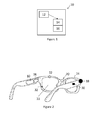
- the invention further relates to a visual fatigue determining device 20 intended to be worn by a user.
- the visual fatigue determining device is a head mounted device comprising a spectacle frame that may comprise optical lenses 22.
- Other head mounted device may be used, in particular head mounted devices that do not comprise optical lenses.
- the visual fatigue determining device 20 may comprise active optical lenses.
- the optical function of the active optical lenses may be controlled by an optical function controller (not shown).
- the visual fatigue determining device 20 can determine that that the eyes of the user are fatigue and alerts the user and/or control the active optical lenses to adapt the optical function to the visual fatigue level of the user.
- the optical function may comprise dioptric function, light absorption, polarizing capability, reinforcement of contrast capacity, etc...
- the dioptric function corresponds to the optical lens power (mean power, astigmatism etc... ) as a function of the gaze direction.
- the optical function of the head mounted device may comprise the dioptric function of at least one of the lenses that the head mounted device may comprise, a sun protection function for example by controlling a transmission parameter of the head mounted device or the polarization of a surface of at least one of the lenses that the head mounted device may comprise.
- the dioptric function may be adapted based on the visual fatigue level by adapting the addition in the near zone to relieve the user from the visual fatigue.
- the color or light absorption of the optical lenses may also be adapted based on the visual fatigue level of the user.
- optical function won't comprise the addition/ tint when it is not needed by the user and thus protecting eyes of the user from unnecessary symptoms of headache, dizziness etc.
- the visual fatigue determining device 20 illustrated on figure 2 further comprises sensors 32 and a communication unit 38.
- the sensors 32 are configured to sense at least one visual behavior parameter indicative of the visual behavior of the user when wearing the visual fatigue determining device.
- binocular or monocular tracking may be user. For example capturing both pupil and then considering worst eye provides good results, monocular tracking is enough for pupilla size monitoring.
- Pupil diameter is measured by image processing.
- a normalization relative to inter-pupillary distance or distance between two nodal points of the face permit to compensate variation of distance between camera and eyes.
- DiamPupNor DiamPupCam / DistPupCam , with DiamPupNorm being the normalized pupil diameter, DiamPupCam being the pupil diam size seen by the camera (size in pixels) and DistPupCam being the interpupilary distance seen by the camera (in pixels).
- the distance variation can be compensated using the size of the IRIS that is constant.
- Spectrum of pupil diameter variation over time may be calculated with Fourier transform. Energy in specific bandwidth are assessed (low is below 1Hz, medium is between 1Hz and 2.5 Hz). From the results low frequency is good enough to measure.
- pupil microfluctuations exceeds a particular threshold in one eye (low frequency component>0.002) or evolves during the day then this would imply that person is visually fatigue and may need anti-fatigue lenses.
- the duration for measurement may typically be between 10 and 20 seconds.
- the vergence fluctuation calculation can be done based on the center of rotation of the eye, interpupillary distance and distance between the camera and the eyes.
- DistPup the actual pupillary distance
- DistPupMoy the average (vs time) pupillary distance
- ⁇ the fluctuation of convergence over a period of time
- the vergence fluctuation can further be determined based on the gaze values of right and left eyes.
- Eyemovement speed can be calculated based on the gaze values of x- and y-coordinates for each eye.
- ⁇ for Right eye can be calculated as [sqrt(alphaR2-alphaR1) ⁇ 2 + (betaR2-betaR1) ⁇ 2]/Time2-Time1; ⁇ being the fluctuation of eye movement.
- Threshold for vergence - low frequency component >0.25 and threshold for eye movement - low frequency component >0.1. Considering low frequency component is good enough for vergence and eye movement microfluctuations.
- the visual fatigue determining device 20 may further sense visual behavior of the user based on the near point of convergence.
- An object or target is positioned at set distances and the user is asked if it appears double or examiner or camera can pick if one of the eyes loses fixation.
- a target is shown which is placed at a particular defined distance and move towards the user and the user fixates at the target tip and reports when the target splits into two or the camera in the tool can detect the deviation of the eye.
- the camera it is also possible to use the camera to display on the tablet screen the position of both eyes, and let the user detect by himself when one of the two eyes deviates.
- Distance from the eyes to the target may be recorded by the camera, or as an alternative can be recorded via a position sensor associated to the target.
- the communication unit 38 is configured to communicate visual behavior data indicative of the sense visual behavior parameter to a visual fatigue determining module 10 according to the invention.
- the communication unit 38 may further be configured to receive from the visual fatigue determining module 10 information indicative of the visual fatigue of the user.
- the visual fatigue determining device 20 may further comprise an output unit arranged to output a signal to the user based on the information indicative of the visual fatigue level of the user received from visual fatigue determining module 10.
- the output unit may be a visual output unit configured to provide a visual signal to the user based on the information indicative of the visual fatigue level.
- Such visual signal output unit may be a simple led or a more complex display device allowing for example to display a text message to the user.
- the output unit may be an audio output unit such as a speaker or an intraocular prosthesis outputting an audio message to the user.
- the output unit may be configured to provide a haptic feedback to the user such as a specific vibration.
- the output unit could be part of a distant entity connected to the visual fatigue determining device or module.
- the output unit may be part a personal digital assistants, an audio/video device, a mobile phone, a MPEG-1 Audio Layer 3 (MP3) player, a personal computer, a laptop, a tablet, a bluetooth headset, a watch, a wristband, etc...
- MP3 MPEG-1 Audio Layer 3
- Such distant entity may typically communicate with the visual fatigue determining device or module by wireless communication.
- the wireless communication can use different communication protocols such a Bluetooth, Zigbee, Wifi or others.
- the visual fatigue determining device 20 may further comprise an activity input unit 18 configured to collect activity information indicative of the activity of the user.
- the activity information may be communicated to the visual fatigue determining module 10 by the communication unit 38.
- the activity input unit 18 may comprise a sensor, such as a scene camera, adapted to determine information concerning the activity of the user.
- the activity input unit 18 may further comprise input means, such as voice control, a keyboard virtual or not, or any device that allows the user to provide an indication of his activity. For example the user may select his activity in a list of activities.
- the user may provide information concerning his past activities and/or future activities.
- the device assessing fatigue is connected to a device currently used by the user as a Smartphone, or a personal computer, the activity may be automatically provided.
- the activity data may be used by the visual fatigue determining module 10 when generating the visual fatigue information.
- the visual fatigue determining module 10 is embedded in the visual fatigue determining device 20.
- the visual fatigue determining module 10 may be a distant entity communicating with the visual fatigue determining device 20.
- the visual fatigue determining device 20 communicates with a distant entity that comprises a visual fatigue determining module 10 according to the invention. Communication can be done through different communication devices and protocols, like Bluetooth, Zigbee, WiFi or others.
- the communication unit may be configured to communicate with the distant entity either to store the measured features in a memory MEM or to provide information indicative of the visual behavior of the user.
- the distant entity comprises a communication module 12 configured to communicate at least with the communication unit 38 of the visual fatigue determining device 20, a memory 14, at least one processor 16 and program instructions stored on a non-transitory computer-readable medium and executable by the at least one processor to execute the steps of the method of the invention.
- the distant entity can include different computing objects such as personal digital assistants, audio/video devices, mobile phones, MPEG-1 Audio Layer 3 (MP3) players, personal computers, laptops, tablets, bluetooth headset, watch, wristband, etc...
- MP3 MPEG-1 Audio Layer 3
- Each computing object and the head mounted device can communicate with one or more other by way of a communication network, either directly or indirectly.
- network can include other computing objects and computing devices that provide services to the system of figure 3 , and/or can represent multiple interconnected networks, which are not shown.
- the computing objects can be Web servers, file servers, media servers, etc. with which the client computing objects or devices communicate via any of a number of known protocols, such as the hypertext transfer protocol (HTTP).
- HTTP hypertext transfer protocol
- the device can be in the form of a simple stick having graduations for distance measurement, one end of the stick is intended to be in contact with the chin of the person, and a target movable along the stick.
- the visual fatigue determining device may be a smartphone comprising the visual fatigue determining module.
- the camera of the phone can be used to sense the distance corresponding to the near point of convergence and if the camera detects 6/8 cm it may display on the screen 'move back' that is, to start from further distance.
- a 'correct distance' or 'proceed' may be displayed.
- a target for example a tower such as the Eiffel tower, may be displayed on the screen and the user looks at the tip of the tower and if tower appears single then click on button 'OK' on the screen and move to next closer distance and if target still appears single click on 'OK' and if double then click on 'double' tab.
- a message may appear on the screen 'moderate fatigue' - needs preventive measures. If the user pushes 'double' tab for the distance of 9 cm then 'severe fatigue' is displayed which implies, need for visual fatigue treatment.
- the camera of the smartphone or touch pad is be able to sense the distance in different ways:
- the camera can be a stereo camera that is able to sense the 3D scene, and so determine the distance of the imaged environment,
- the camera is a standard camera, and known dimension of an imaged object (the head size of the person, or the pupil distance of the person) is provided, so that it is possible to scale the image.
- Another way for visual fatigue assessment may be instead of having the user push the button, is to have the camera arranged to sense when one of the eyes deviates more than the specified convergence range. Depending on the distance from eye to the camera, the user's visual fatigue level is either no fatigue, moderate or severe fatigue.
- One advantage of measuring the loss of convergence using the camera is that the user could suppress one of the images of the R/L eye instead of having double vision, leading to incorrect result, whereas measuring with the camera the convergence of the both eye provides correct results in any cases.
- the device of the invention can be used for a specific process of delivery a lens or service for attenuating visual fatigue.
- antifatigue lens for example, if the distance is in the risk range, antifatigue lens, lens reducing glare, lens reducing reflection, or visual training may be proposed to the user.
- the visual fatigue determining device may be a smartphone and used sense pupilla microflucation.
- the invention further relates to a method of determining the visual fatigue level of a user, comprising:
- visual behavior data indicative of the visual behavior of the user are received, typically by the communication component of the visual fatigue determining module 10 from the communication unit 38 of the visual fatigue determining device 20.
- the received data are processed during the processing step to generate visual fatigue information indicative of the visual fatigue level of the user.
- the method may further comprise, prior to the processing step, an activity data providing step S2.
- activity data providing step S2 activity data indicative of the activity of the user are provided.
- the visual fatigue information may be generated based on the visual behavior data and the activity data.
- the invention also relates to a method for improving a visual fatigue determining module according to the invention.
- the method for improving a visual fatigue determining module comprises:
- Subjective fatigue level data indicative of a subjective fatigue level are provided during the subjective fatigue level data providing step.
- the subjective fatigue level data may be provided by the user or a third party. As indicated previously such data relates to a subjective indication of the visual fatigue level of the user.
- subjective visual behavior data are received during the subjective visual behavior data receiving step S11.
- the subjective visual behavior data are indicative of at least one visual behavior parameter of the user in the subjective fatigue level.
- the computer executable instructions for processing the visual behavior data are adapted based on the subjective fatigue level data and the subjective visual behavior data during the adapting step S12.
Landscapes
- Business, Economics & Management (AREA)
- Emergency Management (AREA)
- Physics & Mathematics (AREA)
- General Physics & Mathematics (AREA)
- Measurement Of The Respiration, Hearing Ability, Form, And Blood Characteristics Of Living Organisms (AREA)
Priority Applications (2)
| Application Number | Priority Date | Filing Date | Title |
|---|---|---|---|
| EP15306071.0A EP3113135A1 (de) | 2015-07-01 | 2015-07-01 | Modul und verfahren zur bestimmung der augenermüdung |
| PCT/EP2016/064805 WO2017001319A1 (en) | 2015-07-01 | 2016-06-27 | A visual fatigue determining module |
Applications Claiming Priority (1)
| Application Number | Priority Date | Filing Date | Title |
|---|---|---|---|
| EP15306071.0A EP3113135A1 (de) | 2015-07-01 | 2015-07-01 | Modul und verfahren zur bestimmung der augenermüdung |
Publications (1)
| Publication Number | Publication Date |
|---|---|
| EP3113135A1 true EP3113135A1 (de) | 2017-01-04 |
Family
ID=53539627
Family Applications (1)
| Application Number | Title | Priority Date | Filing Date |
|---|---|---|---|
| EP15306071.0A Withdrawn EP3113135A1 (de) | 2015-07-01 | 2015-07-01 | Modul und verfahren zur bestimmung der augenermüdung |
Country Status (2)
| Country | Link |
|---|---|
| EP (1) | EP3113135A1 (de) |
| WO (1) | WO2017001319A1 (de) |
Cited By (1)
| Publication number | Priority date | Publication date | Assignee | Title |
|---|---|---|---|---|
| EP4421821A1 (de) * | 2023-02-27 | 2024-08-28 | Essilor International | Berechnungsmodul, system und computerimplementiertes verfahren zur bestimmung mindestens einer ursache einer visuellen ermüdung eines patienten |
Families Citing this family (3)
| Publication number | Priority date | Publication date | Assignee | Title |
|---|---|---|---|---|
| CN108874122A (zh) * | 2018-04-28 | 2018-11-23 | 深圳市赛亿科技开发有限公司 | 智能眼镜及其控制方法、计算机可读存储介质 |
| TWI714173B (zh) * | 2019-01-02 | 2020-12-21 | 見臻科技股份有限公司 | 監控視覺疲勞之方法和光學系統 |
| CN111387933B (zh) | 2019-01-02 | 2023-05-05 | 见臻科技股份有限公司 | 监控视觉疲劳的方法和光学系统 |
Citations (4)
| Publication number | Priority date | Publication date | Assignee | Title |
|---|---|---|---|---|
| US20060214807A1 (en) * | 2005-03-24 | 2006-09-28 | Tengshe Vishwas V | Drowsy driving alarm system |
| DE102008007149A1 (de) * | 2007-03-30 | 2008-10-02 | Volkswagen Ag | Verfahren und Vorrichtung zum Erzeugen, Steuern und Auslösen eines Warnsignals in einem Kraftfahrzeug |
| US8610585B1 (en) * | 2009-12-07 | 2013-12-17 | Matthew Kielbasa | Electronic alerting device and associated method |
| US20140152444A1 (en) * | 2012-12-05 | 2014-06-05 | Hyundai Motor Company | Apparatus for measuring driver's visual fatigue |
Family Cites Families (2)
| Publication number | Priority date | Publication date | Assignee | Title |
|---|---|---|---|---|
| DE10152852A1 (de) * | 2001-10-25 | 2003-05-22 | Daimler Chrysler Ag | System zur Bestimmung und Beeinflussung der emotionalen Verfassung des Fahrers eines Kraftfahrzeugs |
| DE102014204980B4 (de) * | 2013-07-05 | 2017-10-05 | Ford Global Technologies, Llc | Verfahren und Vorrichtung zur Einschränkung oder Zwangsaktivierung von Kraftfahrzeugfunktionen |
-
2015
- 2015-07-01 EP EP15306071.0A patent/EP3113135A1/de not_active Withdrawn
-
2016
- 2016-06-27 WO PCT/EP2016/064805 patent/WO2017001319A1/en not_active Ceased
Patent Citations (4)
| Publication number | Priority date | Publication date | Assignee | Title |
|---|---|---|---|---|
| US20060214807A1 (en) * | 2005-03-24 | 2006-09-28 | Tengshe Vishwas V | Drowsy driving alarm system |
| DE102008007149A1 (de) * | 2007-03-30 | 2008-10-02 | Volkswagen Ag | Verfahren und Vorrichtung zum Erzeugen, Steuern und Auslösen eines Warnsignals in einem Kraftfahrzeug |
| US8610585B1 (en) * | 2009-12-07 | 2013-12-17 | Matthew Kielbasa | Electronic alerting device and associated method |
| US20140152444A1 (en) * | 2012-12-05 | 2014-06-05 | Hyundai Motor Company | Apparatus for measuring driver's visual fatigue |
Cited By (2)
| Publication number | Priority date | Publication date | Assignee | Title |
|---|---|---|---|---|
| EP4421821A1 (de) * | 2023-02-27 | 2024-08-28 | Essilor International | Berechnungsmodul, system und computerimplementiertes verfahren zur bestimmung mindestens einer ursache einer visuellen ermüdung eines patienten |
| WO2024179800A1 (en) * | 2023-02-27 | 2024-09-06 | Essilor International | Calculation module, system and computer-implemented method for determining at least one cause of a visual fatigue of a patient |
Also Published As
| Publication number | Publication date |
|---|---|
| WO2017001319A1 (en) | 2017-01-05 |
Similar Documents
| Publication | Publication Date | Title |
|---|---|---|
| EP3108295B1 (de) | Verfahren zur optimierung einer optischen linseneinrichtung für einen träger | |
| JP7106569B2 (ja) | ユーザーの健康状態を評価するシステム | |
| EP3239870B1 (de) | Verfahren zur überwachung des verhaltens einer kohortengruppe von elementen | |
| EP3834059B1 (de) | Steuerung der fokusparameter einer am kopf montierten anzeige basierend auf geschätztem benutzeralter | |
| US20150138048A1 (en) | Glasses apparatus using eyesight-based virtual image | |
| EP3113135A1 (de) | Modul und verfahren zur bestimmung der augenermüdung | |
| JP2020528333A (ja) | 視力検査試験を実施する方法 | |
| US20230301569A1 (en) | A method and device for providing an automated prediction of a change of a state of fatigue of a subject carrying out a visual task | |
| US20160309998A1 (en) | System and Methods for Assessing Vision Using a Computing Device | |
| US11016295B2 (en) | Eyeglasses wearable device, method of controlling the eyeglasses wearable device and data management server | |
| US11815744B2 (en) | Method for determining a postural and visual behavior of a person | |
| EP3075315B1 (de) | Vorrichtung und computerimplementiertes verfahren zur überwachung des visuellen verhaltens einer person | |
| US8851677B2 (en) | Arrangement with a spectacle lens having a changeable effect and method for setting the effect of a spectacle lens | |
| KR20230065989A (ko) | 광학 디바이스 오-적응 검출 방법 및 장치 | |
| CN120722583B (zh) | 光学调节方法、装置、头显设备及存储介质 | |
| CN120742549B (zh) | 光学调节方法、头显设备及存储介质 | |
| JP7851916B2 (ja) | 視作業を実行する対象者の疲労状態の変化の自動予測を提供する方法及びデバイス | |
| EP4556989A1 (de) | Verfahren und vorrichtungen zur bestimmung mindestens eines brechungswerts | |
| CN121487686A (zh) | 用于评估光致不适的系统及相关联的方法 |
Legal Events
| Date | Code | Title | Description |
|---|---|---|---|
| PUAI | Public reference made under article 153(3) epc to a published international application that has entered the european phase |
Free format text: ORIGINAL CODE: 0009012 |
|
| AK | Designated contracting states |
Kind code of ref document: A1 Designated state(s): AL AT BE BG CH CY CZ DE DK EE ES FI FR GB GR HR HU IE IS IT LI LT LU LV MC MK MT NL NO PL PT RO RS SE SI SK SM TR |
|
| AX | Request for extension of the european patent |
Extension state: BA ME |
|
| 17P | Request for examination filed |
Effective date: 20170628 |
|
| RBV | Designated contracting states (corrected) |
Designated state(s): AL AT BE BG CH CY CZ DE DK EE ES FI FR GB GR HR HU IE IS IT LI LT LU LV MC MK MT NL NO PL PT RO RS SE SI SK SM TR |
|
| GRAP | Despatch of communication of intention to grant a patent |
Free format text: ORIGINAL CODE: EPIDOSNIGR1 |
|
| INTG | Intention to grant announced |
Effective date: 20171024 |
|
| RAP1 | Party data changed (applicant data changed or rights of an application transferred) |
Owner name: ESSILOR INTERNATIONAL |
|
| STAA | Information on the status of an ep patent application or granted ep patent |
Free format text: STATUS: THE APPLICATION IS DEEMED TO BE WITHDRAWN |
|
| 18D | Application deemed to be withdrawn |
Effective date: 20180306 |