EP3113136A1 - Vorrichtung und verfahren zur konfiguration einer brandmeldersteuerung - Google Patents
Vorrichtung und verfahren zur konfiguration einer brandmeldersteuerung Download PDFInfo
- Publication number
- EP3113136A1 EP3113136A1 EP16176017.8A EP16176017A EP3113136A1 EP 3113136 A1 EP3113136 A1 EP 3113136A1 EP 16176017 A EP16176017 A EP 16176017A EP 3113136 A1 EP3113136 A1 EP 3113136A1
- Authority
- EP
- European Patent Office
- Prior art keywords
- configuration
- matrix
- input
- fire alarm
- output
- Prior art date
- Legal status (The legal status is an assumption and is not a legal conclusion. Google has not performed a legal analysis and makes no representation as to the accuracy of the status listed.)
- Withdrawn
Links
Images


Classifications
-
- G—PHYSICS
- G08—SIGNALLING
- G08B—SIGNALLING SYSTEMS, e.g. PERSONAL CALLING SYSTEMS; ORDER TELEGRAPHS; ALARM SYSTEMS
- G08B17/00—Fire alarms; Alarms responsive to explosion
-
- G—PHYSICS
- G08—SIGNALLING
- G08B—SIGNALLING SYSTEMS, e.g. PERSONAL CALLING SYSTEMS; ORDER TELEGRAPHS; ALARM SYSTEMS
- G08B25/00—Alarm systems in which the location of the alarm condition is signalled to a central station, e.g. fire or police telegraphic systems
- G08B25/14—Central alarm receiver or annunciator arrangements
-
- A—HUMAN NECESSITIES
- A62—LIFE-SAVING; FIRE-FIGHTING
- A62C—FIRE-FIGHTING
- A62C37/00—Control of fire-fighting equipment
-
- G—PHYSICS
- G05—CONTROLLING; REGULATING
- G05B—CONTROL OR REGULATING SYSTEMS IN GENERAL; FUNCTIONAL ELEMENTS OF SUCH SYSTEMS; MONITORING OR TESTING ARRANGEMENTS FOR SUCH SYSTEMS OR ELEMENTS
- G05B19/00—Program-control systems
- G05B19/02—Program-control systems electric
- G05B19/04—Program control other than numerical control, i.e. in sequence controllers or logic controllers
- G05B19/042—Program control other than numerical control, i.e. in sequence controllers or logic controllers using digital processors
- G05B19/0426—Programming the control sequence
-
- G—PHYSICS
- G05—CONTROLLING; REGULATING
- G05B—CONTROL OR REGULATING SYSTEMS IN GENERAL; FUNCTIONAL ELEMENTS OF SUCH SYSTEMS; MONITORING OR TESTING ARRANGEMENTS FOR SUCH SYSTEMS OR ELEMENTS
- G05B2219/00—Program-control systems
- G05B2219/20—Pc systems
- G05B2219/23—Pc programming
- G05B2219/23236—Table lookup driven system
-
- G—PHYSICS
- G05—CONTROLLING; REGULATING
- G05B—CONTROL OR REGULATING SYSTEMS IN GENERAL; FUNCTIONAL ELEMENTS OF SUCH SYSTEMS; MONITORING OR TESTING ARRANGEMENTS FOR SUCH SYSTEMS OR ELEMENTS
- G05B2219/00—Program-control systems
- G05B2219/20—Pc systems
- G05B2219/25—Pc structure of the system
- G05B2219/25118—Matrix to connect sensor to corresponding actuator
Definitions
- the present invention relates to the field of fire-fighting, in particular to a configuration apparatus for a fire alarm controller and a configuration method thereof.
- Fig. 1 shows a schematic diagram of a typical fire alarm system.
- various fire detectors, acoustic/optical alarms or manual alarms distributed throughout a building are collectively referred to as peripheral devices 10.
- peripheral devices 10 are connected to a fire alarm controller (control panel) 20 via a wired or wireless network.
- the fire alarm controller 20, also abbreviated as controller 20, receives an input from these peripheral devices 10, for example an alert signal, and monitors the operating state of these peripheral devices 10.
- the controller 20 drives an acoustic/optical alarm 10 for example to issue an alert, to prompt personnel in the building to pay attention and promptly evacuate, or even drives a linked device to act to extinguish the fire.
- the controller in a fire alarm system must generally be configured before use.
- the content of configuration includes the addresses, types, objects of monitoring, and linkage control logic, etc. of the various devices connected to the controller.
- the controller In an existing fire alarm system, the controller generally has a communication interface 22, which can be connected to a terminal device (e.g. a PC or a mobile terminal such as a mobile phone) 30. An operator can use the terminal device 30 to complete various configurations of the controller 20.
- the communication interface 22 can be any suitable interface type, e.g. a serial port, a wired or wireless network interface, a high-speed parallel interface, etc.
- the terminal device 30 at least comprises a display component 32 and an input component 34.
- the display component 32 may be a display screen or a projector.
- the input component 34 may be a mouse, a keyboard, a gesture input capture device, etc.
- linkage control logic is an important part of configuration work.
- the operator must perform linkage logic configuration on devices which have a causal association therebetween according to the way in which wires are connected on site and the installation situation.
- Existing ways of performing linkage logic configuration can broadly be divided into two major types: one is configuration based on logic formula, the other is configuration based on tree logic.
- the present invention proposes a configuration method for a fire alarm controller, the method comprising: presenting a configuration matrix, in which either the rows represent inputs while the columns represent outputs, or the rows represent outputs while the columns represent inputs, with a matrix element in the configuration matrix being binary data, which indicates whether a causal relationship exists between the input and output in the row and column where the matrix element is located, wherein the input is a signal received or sensed by the fire alarm controller, and the output comprises at least one enable signal capable of activating a linked apparatus connected directly or indirectly to the fire alarm controller in response to at least one of the inputs; receiving at least one external input adapted to amend the value of a matrix element in the configuration matrix; according to the amended configuration matrix, generating a configuration file for updating linkage control logic of the fire alarm controller.
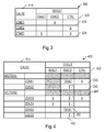
- Fig. 3 shows by way of example a schematic diagram of a manner of configuration according to an embodiment of the present invention.
- a configuration matrix is used to present and realize configuration of linkage control logic.
- a configuration matrix 300 as shown in Fig. 3 is presented on the display component 32 of the terminal device 30 shown in Fig. 1 .
- the configuration matrix 300 shown in Fig. 3 is for example a 3*3 matrix.
- rows represent linkage causes (CAUSE), while columns represent effects (EFFECT) caused when relevant cause conditions are satisfied, i.e. must be set to be a valid output.
- CAUSE linkage causes
- ETFECT effects
- Each matrix element 330 in the configuration matrix 300 may for example be a binary value, i.e. a valid value or invalid value.
- the validity/invalidity of a matrix element 330 can indicate the existence/non-existence of a causal relationship, also called a linkage logic relationship, between the input of the row in which the matrix element 330 is located and the output of the column in which the matrix element is located.
- the content of the matrix element 330 is precisely content which needs to be configured by an operator.
- a configuration program running on the terminal device 30 can generate a corresponding configuration file according to the configuration matrix.
- the configuration file can be downloaded onto the fire alarm controller 20 via the connection between the fire alarm controller 20 and the terminal device 30.
- the fire alarm controller 20 reads the updated configuration file and parses a corresponding logic relationship.
- the fire alarm controller 20 controls the input and output ports thereof according to the configured logic relationship, or configures input and output ports of peripheral devices connected directly or indirectly thereto.
- the rows representing causes comprise inputs received in three different zones, represented by ZONE1, ZONE2 and ZONE3 respectively.
- the zone may be a room, multiple rooms, or an open region of a given area.
- the inputs of the three different zones may be multiple different inputs received or sensed in each zone.
- zones are generally divided into automatic detection zones (Automatic Zones), manual trigger zones (Manual Zones), sprinkling action zones (Sprinkler Zones), etc.
- the inputs of each type of zone differ somewhat.
- an input in an automatic zone may be a fire alert signal from a smoke sensing detector.
- An input in a manual zone may be an input signal that a manual alarm has been triggered.
- An input in a sprinkler zone may be an input that sprinkling has been activated.
- the outputs of the configuration matrix 300 comprise EVAC1, EVAC2 and CTRL.
- EVAC1 and EVAC2 represent outputs for activating an evacuation instruction apparatus, e.g. for activating one or more acoustic/optical alarm(s) in a particular zone.
- the number after EVAC can identify different zones.
- a zone controlled by an evacuation instruction is also called an evacuation zone (EVAC ZONE).
- CTRL represents control outputs.
- Each column in the configuration matrix 300 may correspond to an output for controlling an on-site device or a hardware device. One output may be used to control the action of one or more devices. Multiple different causes may also cause the same output to be valid.
- the example shown in Fig. 3 is a configuration matrix configured by an operator.
- the operator can set the matrix elements to be valid/invalid at the points of intersection of rows and columns, i.e. at the positions of the matrix elements, according to the actual circumstances. If a matrix element is valid (indicated by an X in the figure), this indicates that a causal relationship exists between the row and column in which the matrix element is located.
- the first row/second column is set to a valid value "X", which indicates that a ZONE1 input can cause the EVAC2 output to be valid. For instance, if ZONE1 indicates that a fire has been detected in room no.
- EVAC2 is set to be valid, for the purpose of driving a group of acoustic/optical alarms in a corridor zone outside room no. 1 to begin emitting sound or flashing light.
- the second row/third column is set to be valid "X", which indicates that a ZONE2 input (e.g. a manual alarm) can cause the CTRL output to be valid. For instance, if ZONE2 indicates that a manual alarm in room no. 2 has been activated, then CTRL is set to be valid, for the purpose of driving activation of a sprinkling device associated with room no. 2, so as to extinguish the fire.
- the two matrix elements in the third row/first column and the third row/third column are both set to be valid "X".
- ZONE3 for example receives a fire alert
- the EVAC1 and CTRL outputs are set to be valid simultaneously, i.e. in the case of an alert in room no. 3 for example, an acoustic/optical alarm is activated, and a sprinkling device is activated.
- each valid matrix element represents a causal relationship between an input and an output.
- the operator need only set the point of intersection (matrix element) of a row and column which have a causal relationship to be valid. This simplifies the factors which need to be taken into account by the operator, to facilitate configuration by the operator.
- inputs which might be used as causes e.g. an alert signal or sprinkling action
- outputs which can execute corresponding actions in response to causes are all set out above the columns.
- the operator can see at a glance which zones need to be monitored, and discover whether all of the devices which need to act have been taken into account. At the same time, if a particular row of the configuration matrix is observed, the operator can discover very easily which outputs are caused by an input. Similarly, if a particular column of the configuration matrix is observed, then the operator can discover which causes (inputs) can cause the same output. In this way, the entire configuration matrix can provide the operator with a comprehensive, intuitive configuration result, which facilitates prompt discovery of omissions by the operator.
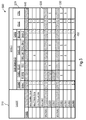
- Fig. 4 shows by way of example a configuration matrix 400 according to an embodiment of the present invention.
- the rows (indicated in the column labeled 410) of the configuration matrix 400 in Fig. 4 also represent inputs (e.g. an alert input, manual alarm input, etc.), while the columns thereof (indicated in sequence in the row labeled 420) likewise represent outputs (e.g. a sprinkling action, acoustic/optical alarm enablement, etc.).
- the cause section in Fig. 4 has a tree structure. As Fig. 4 shows, the causes which serve as rows comprise two levels. A first level is SECTIONS; a second level is ZONES.
- Each section comprises a number of zones. For instance, a first section (SECTION1) comprises two zones, ZONE1 and ZONE2. A second section (SECTION2) comprises four zones, ZONE3 - ZONE6. In this way, the row side of the configuration matrix 400 can provide a level structure which is the same as the actual situation.
- matrix elements 440 have been shaded. These matrix elements 440 represent disabled matrix elements, i.e. no causal relationship exists between the row and column in which the matrix element is located, and the user cannot add a causal relationship therefor.
- a gray region is generally used to identify the disabled matrix element. The presence of disabled matrix elements can avoid a situation where the operator erroneously configures causal logic which should not be there into the fire alarm controller.
- the matrix elements of the second column EVAC1 are the same as in Fig. 3 . If a matrix element is marked as valid "X", this indicates that a causal relationship exists between the row and column in which it is located. This is the same as in Fig. 3 , and will not be repeated here.
- the matrix elements 450 in the third column are not binary values, but instead are parameter selectable matrix elements having multiple parameter options. As Fig. 4 shows, the matrix element 450 may have a pull-down menu button. By clicking this button, the operator can see a number of optional parameters.
- the output of the third column is EVAC2, i.e. an acoustic/optical alarm output.
- the acoustic/optical alarm output may have three optional sound frequencies.
- the operator may select a suitable sound frequency according to the cause in the corresponding row. For example, a sound frequency "TONE2" may be selected for ZONE1 of the first section (SECTION1), whereas a sound frequency "TONE1" may be selected for ZONE5 of the second section (SECTION2).
- Such a parameter selection has two meanings: one is to indicate the causal relationship between ZONE1 and EVAC2 for example, another is to set the parameter for activation of EVAC2 (to emit a sound alert at TONE2).
- the operator can configure the linkage logic and at the same time set the operating mode of the activated device in a single operation.
- the optional parameter may not be limited to the sound frequencies shown in this embodiment, but may also be many other types of parameter, such as flashing light frequency, flashing light intensity, duration of sprinkling, etc.
- Fig. 5 shows a configuration matrix 500 according to another embodiment of the present invention.
- inputs of the fire alarm controller (PANEL) itself are added to the row side of the configuration matrix 500 as causes, and various hardware outputs forming a tree structure are added to the column side of the configuration matrix 500.
- PANEL fire alarm controller
- signals that are received or sensed by the fire alarm controller (PANEL) itself also serve as causes. For instance, ANY SPLINKER ZONE indicates that activation of a sprinkling action in any sprinkler zone is detected at the fire alarm controller side.
- the main board input and output port (MAIN BOARD IO) on the fire alarm controller (PANEL) comprises for example three main types of interface.
- the first type is a sound circuit (SOUND); the specific output interface name thereof is Snder 1.
- the second type is a relay on the main board of the controller (PANEL RELAY); a specific interface thereof comprises for example a remote fire (RT FIRE) or remote fault alert (RT F).
- the third type comprises an input/output interface, PANEL I/O, on the main board of the controller; a specific interface thereof comprises for example system state control outputs FIRE Ctrl1 and FIRE Ctrl2.
- an expansion card CARD
- the configuration matrix 500 also comprises an EVAC output and a CTRL output which are similar to those in Figs. 3 and 4 . It can be seen from Fig. 5 that the outputs which can serve as effects can similarly present the level relationship thereof, or present such a level relationship in the form of a tree. In this way, the operator can intuitively observe the subordination relationship among the hardware outputs, and associate these with the inputs serving as rows as required.
- Fig. 6 shows by way of example a flow chart of the configuration method according to an embodiment of the present invention. As Fig. 6 shows, the configuration method according to the present invention comprises the following steps.
- the program code read from the storage medium is itself capable of realizing the functions of any one of the above embodiments, hence the program code and the storage medium on which the program code is stored form part of the present invention.
- program code read out from the storage medium is written into a memory installed in an expansion board inserted in the computer, or written into a memory installed in an expansion unit connected to the computer, and thereafter commands based on the program code make a CPU etc. installed on the expansion board or expansion unit execute part or all of an actual operation, so as to realize the function of any one of the above embodiments.
Landscapes
- Physics & Mathematics (AREA)
- General Physics & Mathematics (AREA)
- Business, Economics & Management (AREA)
- Emergency Management (AREA)
- Engineering & Computer Science (AREA)
- Automation & Control Theory (AREA)
- Health & Medical Sciences (AREA)
- Public Health (AREA)
- Fire Alarms (AREA)
Applications Claiming Priority (1)
| Application Number | Priority Date | Filing Date | Title |
|---|---|---|---|
| CN201510379709.1A CN106327773A (zh) | 2015-07-01 | 2015-07-01 | 火灾报警控制器的配置装置及其配置方法 |
Publications (1)
| Publication Number | Publication Date |
|---|---|
| EP3113136A1 true EP3113136A1 (de) | 2017-01-04 |
Family
ID=56203252
Family Applications (1)
| Application Number | Title | Priority Date | Filing Date |
|---|---|---|---|
| EP16176017.8A Withdrawn EP3113136A1 (de) | 2015-07-01 | 2016-06-23 | Vorrichtung und verfahren zur konfiguration einer brandmeldersteuerung |
Country Status (3)
| Country | Link |
|---|---|
| US (1) | US9818276B2 (de) |
| EP (1) | EP3113136A1 (de) |
| CN (1) | CN106327773A (de) |
Cited By (3)
| Publication number | Priority date | Publication date | Assignee | Title |
|---|---|---|---|---|
| EP3576065A1 (de) * | 2018-06-01 | 2019-12-04 | Johnson Controls Fire Protection LP | Systeme und verfahren für alarmsteuerungen und zur evakuierung mit geführten audio-anweisungen |
| EP3748597A1 (de) * | 2019-06-04 | 2020-12-09 | Honeywell International Inc. | Feuermeldesystemregelerzeugung |
| US12239866B2 (en) | 2019-08-02 | 2025-03-04 | Tyco Fire Products Lp | Sprinkler box for embedded sprinkler pipe system |
Families Citing this family (7)
| Publication number | Priority date | Publication date | Assignee | Title |
|---|---|---|---|---|
| GB2558817B (en) * | 2015-10-09 | 2022-03-02 | Fisher Rosemount Systems Inc | System and method for verifying the safety logic of a cause and effect matrix |
| US20190196424A1 (en) * | 2017-12-27 | 2019-06-27 | Honeywell International Inc. | Systems and methods for generating a zone configuration and cause and effect logic files |
| GB2592102B (en) | 2018-12-13 | 2023-10-11 | Carrier Corp | A method for commissioning and maintenance of alarm systems |
| US11194460B2 (en) * | 2019-04-01 | 2021-12-07 | Honeywell International Inc. | Systems and methods for commissioning a security system |
| CN110336887A (zh) * | 2019-07-12 | 2019-10-15 | 南京中消安全技术有限公司 | 消防监控系统及其联动控制方法 |
| CN111583610B (zh) * | 2020-04-30 | 2021-07-16 | 深圳市前海用电物联网科技有限公司 | 一种因果模型的消防联动控制方法及系统 |
| CN111583569B (zh) * | 2020-04-30 | 2021-10-08 | 深圳市前海用电物联网科技有限公司 | 一种因果模型的电气火灾检测方法及系统 |
Citations (5)
| Publication number | Priority date | Publication date | Assignee | Title |
|---|---|---|---|---|
| US5402101A (en) * | 1990-11-16 | 1995-03-28 | Esser Sicherheitstechnik Gmbh | Method for determining the configuration of detectors of a danger alarm system and for determining the system configuration of suitable detectors |
| US6448982B1 (en) * | 1998-04-23 | 2002-09-10 | Siemens Energy & Automation, Inc. | System for graphically generating logic for a cause and effects matrix |
| US20070276514A1 (en) * | 2003-12-23 | 2007-11-29 | Abb Research Ltd. | Method In A Safety System For Controlling A Process Or Equipment |
| US20100218962A1 (en) * | 2009-02-27 | 2010-09-02 | Oceano de Dios SA | Fire containment and monitoring system |
| US20130138227A1 (en) * | 2010-07-26 | 2013-05-30 | Katharina Gohr | Method And Viewer For A Cause And Effect Matrix In A Safety System |
Family Cites Families (16)
| Publication number | Priority date | Publication date | Assignee | Title |
|---|---|---|---|---|
| JP2002027573A (ja) * | 2000-07-11 | 2002-01-25 | Matsushita Electric Works Ltd | 通信システム |
| US6545602B2 (en) * | 2000-10-25 | 2003-04-08 | Nohmi Bosai Ltd. | Fire alarm system |
| US6661340B1 (en) * | 2001-04-24 | 2003-12-09 | Microstrategy Incorporated | System and method for connecting security systems to a wireless device |
| US6960987B2 (en) * | 2001-09-21 | 2005-11-01 | Hochiki Corporation | Fire alarm system, fire sensor, fire receiver, and repeater |
| US7233243B2 (en) * | 2004-01-09 | 2007-06-19 | Ctrl Systems, Inc. | Method of defense-in-depth ultrasound intrusion detection |
| US7734572B2 (en) * | 2006-04-04 | 2010-06-08 | Panduit Corp. | Building automation system controller |
| US8773254B2 (en) * | 2010-09-17 | 2014-07-08 | Tyco Fire & Security Gmbh | Automatic configuration of initiating devices |
| US8508359B2 (en) * | 2010-12-17 | 2013-08-13 | Simplexgrinnell Lp | Method and system for wireless configuration, control, and status reporting of devices in a fire alarm system |
| JP5881547B2 (ja) * | 2012-07-05 | 2016-03-09 | 能美防災株式会社 | 火災報知設備 |
| CN202751724U (zh) | 2012-08-14 | 2013-02-27 | 福建师范大学 | 基于物联网的智能消防监控系统 |
| FR3000271B1 (fr) * | 2012-12-21 | 2016-03-11 | Finsecur | Dispositif de detection d'incendie |
| CN203494091U (zh) * | 2013-09-28 | 2014-03-26 | 福建科能中志建设发展有限公司 | 一种消防联动控制系统 |
| ES2588103T3 (es) * | 2014-01-17 | 2016-10-28 | Minimax Gmbh & Co Kg | Procedimiento e instalación para la extinción con un agente extintor sintético líquido y agua |
| CN104299350B (zh) | 2014-09-02 | 2016-08-24 | 杭州航海仪器有限公司 | 一种多冗余可变主从火灾预警监控系统及方法 |
| CN104464158B (zh) | 2014-12-02 | 2016-09-14 | 深圳市泛海三江电子有限公司 | 一种火灾报警的联动控制方法及系统 |
| US9824574B2 (en) * | 2015-09-21 | 2017-11-21 | Tyco Fire & Security Gmbh | Contextual fire detection and alarm verification method and system |
-
2015
- 2015-07-01 CN CN201510379709.1A patent/CN106327773A/zh active Pending
-
2016
- 2016-06-23 EP EP16176017.8A patent/EP3113136A1/de not_active Withdrawn
- 2016-07-01 US US15/200,824 patent/US9818276B2/en active Active
Patent Citations (5)
| Publication number | Priority date | Publication date | Assignee | Title |
|---|---|---|---|---|
| US5402101A (en) * | 1990-11-16 | 1995-03-28 | Esser Sicherheitstechnik Gmbh | Method for determining the configuration of detectors of a danger alarm system and for determining the system configuration of suitable detectors |
| US6448982B1 (en) * | 1998-04-23 | 2002-09-10 | Siemens Energy & Automation, Inc. | System for graphically generating logic for a cause and effects matrix |
| US20070276514A1 (en) * | 2003-12-23 | 2007-11-29 | Abb Research Ltd. | Method In A Safety System For Controlling A Process Or Equipment |
| US20100218962A1 (en) * | 2009-02-27 | 2010-09-02 | Oceano de Dios SA | Fire containment and monitoring system |
| US20130138227A1 (en) * | 2010-07-26 | 2013-05-30 | Katharina Gohr | Method And Viewer For A Cause And Effect Matrix In A Safety System |
Non-Patent Citations (1)
| Title |
|---|
| SIEMENS ENERGY & AUTOMATION INC: "QUADLOG Safety Matrix", 1 January 2004, PRODUCT BROCHURE SIEMENS, PAGE(S) 1 - 6, XP002632845 * |
Cited By (5)
| Publication number | Priority date | Publication date | Assignee | Title |
|---|---|---|---|---|
| EP3576065A1 (de) * | 2018-06-01 | 2019-12-04 | Johnson Controls Fire Protection LP | Systeme und verfahren für alarmsteuerungen und zur evakuierung mit geführten audio-anweisungen |
| US10937285B2 (en) | 2018-06-01 | 2021-03-02 | Johnson Controls Fire Protection LP | Systems and methods of alarm controls and directed audio evacuation |
| EP3748597A1 (de) * | 2019-06-04 | 2020-12-09 | Honeywell International Inc. | Feuermeldesystemregelerzeugung |
| US11338161B2 (en) | 2019-06-04 | 2022-05-24 | Honeywell International Inc. | Fire system rule generation |
| US12239866B2 (en) | 2019-08-02 | 2025-03-04 | Tyco Fire Products Lp | Sprinkler box for embedded sprinkler pipe system |
Also Published As
| Publication number | Publication date |
|---|---|
| US20170004693A1 (en) | 2017-01-05 |
| US9818276B2 (en) | 2017-11-14 |
| CN106327773A (zh) | 2017-01-11 |
Similar Documents
| Publication | Publication Date | Title |
|---|---|---|
| US9818276B2 (en) | Fire alarm controller configuration apparatus and configuration method thereof | |
| US10546470B2 (en) | Mobile user interfaces for smart-home hazard detection devices | |
| US6829513B2 (en) | Fire detection system and method for configuring | |
| CA2684901C (en) | Method and system for testing a building control system | |
| TWI590205B (zh) | 火災信號接受機 | |
| US20150142898A1 (en) | Cloud-based method and apparatus for configuring a fire panel | |
| US20160065721A1 (en) | Emergency communication device | |
| US20040051739A1 (en) | Alarm graphic editor with automatic update | |
| US9076316B2 (en) | System and method for verifying associations between intiating devices and notifications applicances in alarm systems | |
| CA2938693C (en) | Identifying related items associated with devices in a building automation system based on a coverage area | |
| CA2968502A1 (en) | Systems and methods for addressably programming a notification safety device | |
| JP5843713B2 (ja) | 火災受信機 | |
| EP4216185A1 (de) | Aktualisierung der firmware einer brandmeldezentrale unter verwendung von maschinenlernen | |
| HK1229043A1 (en) | Configuration apparatus and configuration method for a fire alarm controller | |
| HK1229043A (en) | Configuration apparatus and configuration method for a fire alarm controller | |
| US10802696B2 (en) | Controlling and monitoring a smoke control system | |
| JP5972724B2 (ja) | 監視制御システム | |
| JP6945465B2 (ja) | 防災監視システム用受信機 | |
| JP2016143007A (ja) | 学習支援装置、学習支援方法及び学習支援プログラム | |
| US9842486B2 (en) | User interface configuration for alarm systems | |
| KR101992678B1 (ko) | 플랜트용 디지털 경보 시스템 및 방법 | |
| CN113557510B (zh) | 安全器具扩展 | |
| JP6173418B2 (ja) | 監視システムシミュレータ | |
| JP2012053577A (ja) | 火災受信機および防災システム | |
| US20230400844A1 (en) | Monitoring apparatus, display method, program, and monitoring system |
Legal Events
| Date | Code | Title | Description |
|---|---|---|---|
| PUAI | Public reference made under article 153(3) epc to a published international application that has entered the european phase |
Free format text: ORIGINAL CODE: 0009012 |
|
| STAA | Information on the status of an ep patent application or granted ep patent |
Free format text: STATUS: THE APPLICATION HAS BEEN PUBLISHED |
|
| AK | Designated contracting states |
Kind code of ref document: A1 Designated state(s): AL AT BE BG CH CY CZ DE DK EE ES FI FR GB GR HR HU IE IS IT LI LT LU LV MC MK MT NL NO PL PT RO RS SE SI SK SM TR |
|
| AX | Request for extension of the european patent |
Extension state: BA ME |
|
| STAA | Information on the status of an ep patent application or granted ep patent |
Free format text: STATUS: THE APPLICATION IS DEEMED TO BE WITHDRAWN |
|
| 18D | Application deemed to be withdrawn |
Effective date: 20170705 |