EP3113579B1 - Système d'éclairage à del et dispositif de commande, procédé de commande d'une pluralité de del et programme informatique associé - Google Patents
Système d'éclairage à del et dispositif de commande, procédé de commande d'une pluralité de del et programme informatique associé Download PDFInfo
- Publication number
- EP3113579B1 EP3113579B1 EP15175023.9A EP15175023A EP3113579B1 EP 3113579 B1 EP3113579 B1 EP 3113579B1 EP 15175023 A EP15175023 A EP 15175023A EP 3113579 B1 EP3113579 B1 EP 3113579B1
- Authority
- EP
- European Patent Office
- Prior art keywords
- leds
- string
- temperature
- heatsink
- strings
- Prior art date
- Legal status (The legal status is an assumption and is not a legal conclusion. Google has not performed a legal analysis and makes no representation as to the accuracy of the status listed.)
- Active
Links
Images




Classifications
-
- H—ELECTRICITY
- H05—ELECTRIC TECHNIQUES NOT OTHERWISE PROVIDED FOR
- H05B—ELECTRIC HEATING; ELECTRIC LIGHT SOURCES NOT OTHERWISE PROVIDED FOR; CIRCUIT ARRANGEMENTS FOR ELECTRIC LIGHT SOURCES, IN GENERAL
- H05B45/00—Circuit arrangements for operating light-emitting diodes [LED]
- H05B45/10—Controlling the intensity of the light
- H05B45/18—Controlling the intensity of the light using temperature feedback
-
- H—ELECTRICITY
- H05—ELECTRIC TECHNIQUES NOT OTHERWISE PROVIDED FOR
- H05B—ELECTRIC HEATING; ELECTRIC LIGHT SOURCES NOT OTHERWISE PROVIDED FOR; CIRCUIT ARRANGEMENTS FOR ELECTRIC LIGHT SOURCES, IN GENERAL
- H05B45/00—Circuit arrangements for operating light-emitting diodes [LED]
- H05B45/50—Circuit arrangements for operating light-emitting diodes [LED] responsive to malfunctions or undesirable behaviour of LEDs; responsive to LED life; Protective circuits
-
- F—MECHANICAL ENGINEERING; LIGHTING; HEATING; WEAPONS; BLASTING
- F21—LIGHTING
- F21V—FUNCTIONAL FEATURES OR DETAILS OF LIGHTING DEVICES OR SYSTEMS THEREOF; STRUCTURAL COMBINATIONS OF LIGHTING DEVICES WITH OTHER ARTICLES, NOT OTHERWISE PROVIDED FOR
- F21V29/00—Protecting lighting devices from thermal damage; Cooling or heating arrangements specially adapted for lighting devices or systems
- F21V29/50—Cooling arrangements
- F21V29/70—Cooling arrangements characterised by passive heat-dissipating elements, e.g. heat-sinks
-
- H—ELECTRICITY
- H05—ELECTRIC TECHNIQUES NOT OTHERWISE PROVIDED FOR
- H05B—ELECTRIC HEATING; ELECTRIC LIGHT SOURCES NOT OTHERWISE PROVIDED FOR; CIRCUIT ARRANGEMENTS FOR ELECTRIC LIGHT SOURCES, IN GENERAL
- H05B45/00—Circuit arrangements for operating light-emitting diodes [LED]
- H05B45/10—Controlling the intensity of the light
-
- H—ELECTRICITY
- H05—ELECTRIC TECHNIQUES NOT OTHERWISE PROVIDED FOR
- H05B—ELECTRIC HEATING; ELECTRIC LIGHT SOURCES NOT OTHERWISE PROVIDED FOR; CIRCUIT ARRANGEMENTS FOR ELECTRIC LIGHT SOURCES, IN GENERAL
- H05B45/00—Circuit arrangements for operating light-emitting diodes [LED]
- H05B45/20—Controlling the colour of the light
-
- H—ELECTRICITY
- H05—ELECTRIC TECHNIQUES NOT OTHERWISE PROVIDED FOR
- H05B—ELECTRIC HEATING; ELECTRIC LIGHT SOURCES NOT OTHERWISE PROVIDED FOR; CIRCUIT ARRANGEMENTS FOR ELECTRIC LIGHT SOURCES, IN GENERAL
- H05B45/00—Circuit arrangements for operating light-emitting diodes [LED]
- H05B45/40—Details of LED load circuits
- H05B45/44—Details of LED load circuits with an active control inside an LED matrix
- H05B45/46—Details of LED load circuits with an active control inside an LED matrix having LEDs disposed in parallel lines
-
- H—ELECTRICITY
- H05—ELECTRIC TECHNIQUES NOT OTHERWISE PROVIDED FOR
- H05B—ELECTRIC HEATING; ELECTRIC LIGHT SOURCES NOT OTHERWISE PROVIDED FOR; CIRCUIT ARRANGEMENTS FOR ELECTRIC LIGHT SOURCES, IN GENERAL
- H05B45/00—Circuit arrangements for operating light-emitting diodes [LED]
- H05B45/50—Circuit arrangements for operating light-emitting diodes [LED] responsive to malfunctions or undesirable behaviour of LEDs; responsive to LED life; Protective circuits
- H05B45/56—Circuit arrangements for operating light-emitting diodes [LED] responsive to malfunctions or undesirable behaviour of LEDs; responsive to LED life; Protective circuits involving measures to prevent abnormal temperature of the LEDs
-
- F—MECHANICAL ENGINEERING; LIGHTING; HEATING; WEAPONS; BLASTING
- F21—LIGHTING
- F21Y—INDEXING SCHEME ASSOCIATED WITH SUBCLASSES F21K, F21L, F21S and F21V, RELATING TO THE FORM OR THE KIND OF THE LIGHT SOURCES OR OF THE COLOUR OF THE LIGHT EMITTED
- F21Y2103/00—Elongate light sources, e.g. fluorescent tubes
- F21Y2103/10—Elongate light sources, e.g. fluorescent tubes comprising a linear array of point-like light-generating elements
-
- F—MECHANICAL ENGINEERING; LIGHTING; HEATING; WEAPONS; BLASTING
- F21—LIGHTING
- F21Y—INDEXING SCHEME ASSOCIATED WITH SUBCLASSES F21K, F21L, F21S and F21V, RELATING TO THE FORM OR THE KIND OF THE LIGHT SOURCES OR OF THE COLOUR OF THE LIGHT EMITTED
- F21Y2115/00—Light-generating elements of semiconductor light sources
- F21Y2115/10—Light-emitting diodes [LED]
-
- H—ELECTRICITY
- H05—ELECTRIC TECHNIQUES NOT OTHERWISE PROVIDED FOR
- H05B—ELECTRIC HEATING; ELECTRIC LIGHT SOURCES NOT OTHERWISE PROVIDED FOR; CIRCUIT ARRANGEMENTS FOR ELECTRIC LIGHT SOURCES, IN GENERAL
- H05B45/00—Circuit arrangements for operating light-emitting diodes [LED]
- H05B45/20—Controlling the colour of the light
- H05B45/28—Controlling the colour of the light using temperature feedback
Definitions
- This present disclosure relates to LED lighting systems, controllers therefor, and to methods of controlling a plurality of LEDs.
- junction temperature of an LED can be useful to control the output of the LED.
- the peak wavelength and perceived colour of an LED depends on the operating temperature.
- the luminous intensity of an LED can vary with temperature.
- the temperature in the critical region - that is to say, the junction which is typically a pn junction for a conventional LED - is generally not directly accessible.
- a temperature sensor may typically be mounted on the heatsink, and the temperature of the LED estimated from the measured heatsink temperature, by generating a thermal model of the arrangement, in order to estimate a temperature off-set between the measured heatsink temperature and the LED junction.
- the applicant has refined these techniques to provide an estimation of the junction temperature from the voltage across the LED at a high current, and the voltage across the LED at a relatively lower current.
- the high current may be of the order of 10mA to 10A
- the relatively lower current may be of the order of 100 ⁇ A or less.
- an LED lighting system comprising: a heatsink; a plurality of strings of LEDs each having a junction and being mounted on the heatsink, and a controller comprising a memory unit and a processor and being configured to supply a current to each of the strings of LEDs; wherein the processor comprises: a first temperature estimation subunit configured to generate a first estimate, being an estimate of a junction temperature of the LEDs of a one of the strings of LEDs; a heatsink temperature estimation subunit configured to estimate a temperature of the heatsink unit from the first estimate; and a second temperature estimation subunit configured to provide a second estimate, being an estimate of a junction temperature of the LEDs of a second string of LEDs, from the estimated temperature of the heatsink.
- a separate temperature-measuring component or circuitry is not required for each of the strings of LEDs.
- the system provides that an estimation of a single string of LEDs' junction temperature be used to estimate the junction temperatures of others of a plurality of LEDs, sharing the same heatsink.
- this aspect it is not required to directly estimate the junction temperature of all of the strings of LEDs.
- this aspect relies on calculating the heatsink temperature from an LED string's junction temperature.
- the present inventors have appreciated that, at least for present purposes, it can be beneficial to estimate a heatsink temperature from the temperature of an operating LED, rather than vice-versa.
- the controller unit is configured to supply a PWM current to the first string of LEDs during an estimation phase during which the PWM current has (a) a high current time, and (b) a low current time during which the PWM current is non-zero.
- the PWM current may be supplied as alternating high-current and low-current times ("high-low"), the low current being sufficiently small that the light emitted by the LEDs is negligible.
- the PWM current may be "high-low" during only an estimation phase, or may be high-low during other operational times (for instance when the LEDs are providing a luminous output but the temperature is not being estimated).
- low-current time of the PWM may not occupy the entire gap between pulses, as will be described in more detail below.
- the first temperature estimation subunit is configured to provide the estimate of the temperature of the junctions of the first string of LEDs during the estimation phase, from a difference between a voltage across the first string of LEDs during the high current part, and a voltage across the first string of LEDs during the low current part.
- the controller unit is configured to supply a PWM pulse having a high current part and a low current part
- the first temperature estimation subunit is configured to provide the estimate of the junction temperature of the LEDs of the first string of LEDs from a voltage across the first string of LEDs during the low current part.
- the heatsink temperature estimation subunit is configured to estimate the heatsink from an average current through the first string of LEDs and the estimated junction temperature of the LEDs of the first string of LED.
- the average current may be defined as the total charge passing through the LED divided by the PWM period.
- the PWM consists of a high current (I_high) and zero current
- the average current is then simply given by I_high multiplied by the PWM duty cycle (which lies between 0, that is to say permanently off and 1 or 100%, that is to say permanently on).
- the memory unit is configured to store a lookup table defining a temperature difference between junction temperature of the LEDs of the first string of LEDs and the heatsink temperature for a plurality of average currents
- the heatsink temperature estimation subunit is configured to estimate the heatsink temperature using the lookup table.
- the lookup table may further define a temperature difference between junction temperature of the LEDs of the second string of LEDs and the heatsink temperature for a plurality of average currents
- the second LED estimation subunit is configured to estimate the junction temperature of the LEDs of the second string of LEDs using the lookup table.
- Such a lookup table may be relatively intensive on memory - but relatively light on processing requirements.
- the LED system comprises a string of red LEDs, a string of blue LEDs a string of green LEDs and a string of white LEDs, and the first string of LEDs is the string of red LEDs.
- the plurality of strings of LEDs further comprises a string of white LEDs.
- a controller configured for use in an LED system having a heatsink and a plurality of strings of LEDs (110, 111, 112, 113) each string comprising one or more LEDs each having a junction (115) and being mounted on the heatsink, the controller comprising: a memory unit (310) and a processor (320) and being configured to supply a respective current to each of the strings of LEDs; wherein the processor comprises: a first temperature estimation subunit (322) configured to generate a first estimate, being an estimate of the junction temperature of the LEDs of a one of the strings of LEDs; a heatsink temperature estimation subunit (324) configured to estimate a temperature of the heatsink unit from the first estimate; and a second temperature estimation subunit (326) configured to provide a second estimate, being an estimate of a junction temperature of LEDs of a second string of LEDs, from the estimated temperature of the heatsink.
- a method of estimating the junction temperature of the LEDs of at least two strings of LEDs from a plurality of strings of LEDs each LED having a junction and mounted on a common heatsink and being supplied by a respective PWM current comprising: estimating the junction temperature of the LEDs of a first string of LEDs of the plurality of strings of LEDs; calculating or estimating the temperature of the heatsink from the estimate of the junction temperature of the LEDs of the first string of LEDs; and estimating the temperature of a second string of LEDs of the plurality of strings of LEDs from the estimated temperature of the heatsink.
- estimating the temperature of the LEDs of the first string of LEDs comprises measuring a first voltage across the first string of LEDs during a high current part of a first LED PWM current, measuring a second voltage across the first string of LEDs during a low current part of a first LED PWM current, and estimating the junction temperature of the LEDs of the first string of LEDs from a difference between the first and second voltages.
- the temperature of the heatsink is estimated from an average current through the first string of LEDs and the estimated junction temperature of the LEDs of the first string of LEDs.
- a temperature offset between the junction temperatures of the first string of LEDs and the heatsink may be estimated from the average current.
- a temperature offset between the junction temperature of the LEDs of the first LED and the heatsink is determined from the average current using a lookup table.
- the junction temperature of the second string of LEDs of the plurality of strings of LEDs is estimated from the estimated temperature of the heatsink and an average current through the second string of LEDs.
- the plurality of strings of LEDs comprises a string of red LEDs being the first string of LEDs, and at least one of a string of blue LEDs and a string of green LEDs. In one or more other embodiments the plurality of strings of LEDs further comprises a string of white LEDs.
- the computer program may be a software implementation, and the computer may be considered as any appropriate hardware, including a digital signal processor, a microcontroller, and an implementation in read only memory (ROM), erasable programmable read only memory (EPROM) or electronically erasable programmable read only memory (EEPROM), as non-limiting examples.
- the software implementation may be an assembly program.
- the computer program may be provided on a computer readable medium, which may be a physical computer readable medium, such as a disc or a memory device, or may be embodied as a transient signal.
- a transient signal may be a network download, including an internet download.
- FIG. 1 shows a block diagram of an LED system 100 according to the present disclosure.
- the LED system comprises a plurality of strings of LEDs 110, 111, 112, 113, the LEDs being are mounted on a common heatsink 120.
- the LEDs may be attached to the heatsink 120 by for instance a eutectic material or a high thermal conductivity adhesive 118, or by other methods with which the skilled person will be familiar.
- the LEDs are thereby in good thermal contact with the heatsink.
- the LEDs each have a junction 115. In the case of conventional LEDs the junction is a pn junction.
- the LEDs are electrically coupled to a controller 300 by means of electrical connections 130, 140.
- the electrical connections 130, 140 respectively connect opposite sides of the PN junction 115 of the LED 110 to the controller 300.
- the junctions of the LEDs are connected in series, and the electrical connections 130, 140 for that string or strings are respectively connected to the N-side or cathode of a first LED in the string and the P-side or anode of a last LED in the string.
- there may be a common ground, or earth electrical connection which may be, for instance, provided through the heatsink 120.
- Figure 2 shows, schematically, a plan view of an arrangement comprising 4 strings of LEDs 110, 111, 112 and 113, each string comprising 3 LEDs connected in series, and the strings being connectable to a controller (not shown) by means of electrical connections 130, 140.
- the strings of LEDs are mounted on a common heatsink 120.
- each string of LEDs 110 may be a single LED or a series-connected plurality of LEDs.
- each string of LEDs comprises between 1 and 20 LEDs; 20 red LEDs may be operated in series provided from a 50V supply, which would generally be considered to be safe.
- the number of LEDs in the string is not limited to 20.
- the strings of LEDs 110..113 respectively are red LEDs 110, blue LEDs 111, green LEDs 112 and white LEDs 113.
- the strings may each be the same colour.
- the strings may be separately controllable, that is to say, a different current level may be provided to each of the strings.
- the current provided to each of the strings may vary with the colour of the LEDs in the string. Varying the current in dependence on the string colour may be useful in order to vary the perceived colour of the overall light output.
- the current provided to each of the strings may vary with their spatial position on the heatsink. Varying the current to each string, in dependence on its spatial position on the heatsink, may be useful for instance to provide beamforming.
- FIG. 3 shows, schematically, a block diagram of a controller 300 according to one or more embodiments.
- the controller 300 comprises a memory unit 310, and a processor 320.
- the processor 320 comprises a first temperature estimation subunit 322, a heatsink temperature estimation subunit 324, and a second temperature estimation subunit 326.
- the processor 320 may comprise one or more PWM generators 328.
- the controller 300 receives as inputs, a requested luminous intensity 351, 352, 353, 354 for each of the strings of LEDs, and the voltage at low current 331 for the red string; it provides as outputs a respective average operating current 361, 362, 363, 364 for each of the strings of LEDs.
- the average current may be a constant current, or may be a PWM current, as will be explained in more detail hereinbelow.
- the output of an LED depends on the junction temperature of the LED.
- output may refer to one or both of intensity and peak wavelength.
- each of the LEDs in a string of LEDs has similar characteristics. In the case that the string consists of just one LED, this is necessarily the case a fortiori; in this case that the string consists of two or more LEDs, it is thus the case that the LEDs should be appropriately similar. For some applications it may be required that the LEDs are matched; however, in general this has not been found to be necessary.
- the LEDs are of the same or similar type or nominal output colour - for example they may all be 'red' LEDs, or all be 'white' LEDs. In other applications even this is not required - in particular, the sensor-less sensing techniques developed by the applicant may be used for characterization of temperature and light (for a string with any combination of LEDs provided only that there is consistency between a characterization (reference) lamp and the production lamps.
- junction temperature in relation to a string is used to refer to the average of the junction temperatures of the individual LEDs in the string.
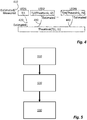
- FIG 4 this figure illustrates, schematically, a method according to the present disclosure.
- the method comprises three elements or steps.
- a first element or step the junction temperature Tj1 of the LED or LEDs in a first string, is estimated or measured, under operating conditions having an average current 11, as shown as 410.
- the estimate Tj1 is then used in a second element of step, in order to estimate the temperature of the heatsink, (Theatsink), as shown at 420
- the junction temperature Tj2 of the second string of LEDs is estimated from the heatsink temperature and the average current 12, as shown at 430.
- the method may be extended to estimate the junction temperature (TjN) of each of one or more further strings of LEDs, as shown at 440.
- the third step may be repeated, for each of the LEDs strings with the exception of the first, or reference string.
- the junction temperature Tj1 of LED or LEDs in the first string is estimated, or polled, on a relatively infrequent basis, and the temperatures of the other strings are estimated relatively frequently, using the third step; the third step may thus be iterated multiple times.
- the temperature of the heatsink depends on the total thermal input to the heatsink and that depends on the current through all of the strings of LEDs.
- FIG. 5 A flow chart corresponding to such a method is shown in figure 5 : at 510 the temperature of the first string is estimated. This is done by directly measuring the junction temperature by a so-called "sensorless sensing" method. At 520 the temperature of the heatsink is estimated. This estimation uses the temperature of the first string, and the average current through the first string in order to determine the offset between the junction temperature of the first string and the temperature of the heatsink. At 530 the temperature of one or more other strings is estimated using the temperature of the heatsink and the average current through that other string.
- a thermal model of the LED system may be used.
- the temperature difference between the heatsink and LED junction depends on the average current through the LED: this determines the heat generated by the LED, and the thermal conductivity of the LED itself (together with any mounting eutectic, compound or adhesive 118) will determine the temperature difference, or offset, between the LED junction and the heatsink.
- the temperature offset may be estimated, or may be measured.
- An example of measurements of the temperature offset, dT is shown in figure 6 in which the offset dT is measured against average current, for four types of LED.
- the four types of LED are red, R 610, blue, B, 620, white, W, 630 and green G, 640.
- the slope of the temperature offset varies between the four different types of LED.
- the average current is varied by a providing a PWM current (with a fixed high current value during the "on" pulse) with a PWM duty cycle which is varied between 10% and 90%.
- a PWM current with a fixed high current value during the "on" pulse
- a PWM duty cycle which is varied between 10% and 90%.
- a look-up table may be used, in which the values of the offset are recorded at different PWM duty cycles for the various types of LEDs.
- the lookup table may be stored in memory unit 310.
- a best fit may be applied to the curve relating the temperature offset to the PWM duty cycle (or average current).
- Figure 6 shows an example of a linear best fit calculation; the coefficients of the best fit curves may be stored in memory unit 310.
- a linear best fit may be used as shown, or a more sophisticated model may be used by determining for instance a quadratic or higher polynomial best fit curve.
- the junction temperatures of just one LED string need be estimated, in particular by directly estimating the junction temperature by use of a "sensorless sensing" technique.
- This LED string may be considered as the reference LEDs string.
- the choice of which string is to be used as the reference LED string may depend on the specific application: in some applications such as specific types of lamp it might be appropriate to choose the LED string which has the greatest impact on the lamp's output, requiring the maximum precision of junction temperature knowledge.
- This may typically be a red LED string since the luminous flux of red LEDs typically demonstrates a very strong dependence on temperature. In other applications it may be appropriate to use the LED string for which the thermal resistance to the heatsink is the least.
- Operation of a method as just described may result in the current through one or more of the strings being varied, with a consequential effect on the temperature of the heatsink. Since the temperature of the junctions in the reference, or first, string depends on the temperature of the heatsink, it may be required to iterate the method multiple times in order to derive accurate temperatures.
- the strings are each supplied with a PWM signal I(t).
- lavg I_high x D.
- the PWM generator requires to have knowledge of the temperature of the string.
- the PWM generator for the reference string (shown as (R)) makes direct use of the estimated temperature of the reference string, as calculated in the temperature estimation subunit 322.
- the PWM generators for the other strings (shown as (G), (B), and (W) make use of the temperature estimated by the respective temperature estimation subunit or subunits 326.
- a single temperature estimation subunit may provide the estimates for each of the strings as shown, or the estimates may be made by separate temperature estimation subunits.
- the term "constant current” refers to a current which is not PWM modulated, rather than a totally time-invariant current. In practice, the current may vary slowly over time: for example as a lamp heats up, the "constant" current may be varied in order to keep the light output constant. Furthermore, a user may change a lamp's settings over time.
- the system may poll the reference string in order to determine the temperature of the junctions, at every PWM cycle.
- the reference string may be polled less frequently, for instance at 100ms intervals, or 1s intervals.
- the temperature may be expected not to vary or fluctuate rapidly, and a low frequency of polling (such as at 1s or longer intervals) will generally reduce the calculation burden on the system.
- An estimation phase may occur relatively infrequently, such as at intervals of 1s or longer.
- a multilevel PWM signal may be used, such as will be familiar to the person skilled in the art of senseless and sensing.
- Such a multilevel PWM signal may include an "on” or “high” time during which the LED is providing luminous output; the gap between these pulses may incorporate both a “low” time during which the temperature of the junction is determined, and an “off' or zero time.
- subunits 322, 324 and 326 are shown as separate elements of the processor 320, along with separate PWM generators, the functions provided by the subunits may be combined into a single subunit or differently distributed between subunits; in the instance of implementation of methods according to the present disclosure either partly or completely in software, the subunits may form a separate or overlapping routines comprised in a set of operating instructions.
- FIG. 7 shows a block diagram of a controller according to one or more embodiments of the present disclosure.
- This controller 700 comprises a processor 320.
- the processor 320 may comprise a first temperature estimation subunit 322, a heatsink temperature estimation subunit 324, and a second temperature estimation subunit 326. These subunits may all be configured or arranged as part of a temperature estimator block 720.
- the controller may further comprise a colour mixer/stabilizer subunit 710.
- the colour mixer/stabilizer subunit 710 may, for instance, use a fixed corners algorithm to stabilise and/or mix the colours from the separate LEDs strings.
- the required red, green and blue intensities may be input to the colour mixer/stabilizer sub-unit 710.
- the temperature estimator block may receive as an input 331 the voltage at low current for the red string, and the PWM levels for each string, and provide, as output to the colour mixer/stabilizer subunit 710 temperature estimates for each string.
Landscapes
- Engineering & Computer Science (AREA)
- General Engineering & Computer Science (AREA)
- Circuit Arrangement For Electric Light Sources In General (AREA)
- Led Devices (AREA)
Claims (15)
- Contrôleur (300) configuré pour être utilisé dans un système d'éclairage à DEL ayant un dissipateur thermique (120) et une pluralité de chaînes de DEL (110, 111, 112, 113), chaque chaîne comprenant une ou plusieurs DEL, chacune ayant une jonction (115) et étant montée sur le dissipateur thermique, le contrôleur comprenant :une unité de mémoire (310) ; et un processeur (320), et étant configuré pour délivrer un courant respectif à chacune des chaînes de DEL ;caractérisé en ce que le processeur comprend : une première sous-unité d'estimation de température (322) configurée pour générer une première estimation, qui est une estimation de la température de jonction des DEL d'une première chaîne de DEL de la pluralité de chaînes de DEL ; une sous-unité d'estimation de température de dissipateur thermique (324) configurée pour estimer une température de l'unité de dissipateur thermique à partir de la première estimation ; et une deuxième sous-unité d'estimation de température (326) configurée pour fournir une deuxième estimation, qui est une estimation d'une température de jonction des DEL d'une deuxième chaîne de DEL de la pluralité de chaînes de DEL, à partir de la température estimée du dissipateur thermique.
- Contrôleur selon la revendication 1, le contrôleur étant configuré pour délivrer un courant PWM à la première chaîne de DEL pendant une phase d'estimation comprenant un temps de courant fort et un temps de courant faible, le courant PWM étant un courant fort (I_high) pendant le temps de courant fort et un courant non nul pendant un temps de courant faible.
- Contrôleur selon la revendication 2, dans lequel la première sous-unité d'estimation de température est configurée pour fournir l'estimation de la température de jonction des DEL de la première chaîne de DEL pendant la phase d'estimation à partir d'une différence entre une tension aux bornes de la première chaîne de DEL pendant le temps de courant fort et une tension aux bornes de la première chaîne de DEL pendant le temps de courant faible.
- Contrôleur selon la revendication 2, dans lequel la première sous-unité d'estimation de température est configurée pour fournir l'estimation de la température de jonction des DEL de la première chaîne de DEL à partir d'une tension aux bornes de la première chaîne de DEL pendant le temps de courant faible.
- Contrôleur selon une quelconque revendication précédente, dans lequel la sous-unité d'estimation de température de dissipateur thermique est configurée pour estimer la température de dissipateur thermique à partir d'un courant moyen à travers la première chaîne de DEL et de la température de jonction estimée des DEL de la première chaîne de DEL.
- Contrôleur selon la revendication 5, dans lequel l'unité de mémoire est configurée pour stocker une table de conversion définissant une différence de température entre la température de jonction des DEL de la première chaîne de DEL et la température de dissipateur thermique pour une pluralité de courants moyens à travers la première chaîne de DEL, et la sous-unité d'estimation de température de dissipateur thermique est configurée pour estimer la température de dissipateur thermique en utilisant la table de conversion.
- Système d'éclairage à DEL comprenant :un dissipateur thermique (120) ;une pluralité de chaînes de DEL (110, 111, 112, 113), chaque chaîne comprenant une ou plusieurs DEL, chacune ayant une jonction (115) et étant montée sur le dissipateur thermique ; etun contrôleur selon une quelconque revendication précédente.
- Système d'éclairage à DEL selon la revendication 7, comprenant une chaîne de DEL rouges, une chaîne de DEL bleues et une chaîne de DEL vertes, et dans lequel la première chaîne de DEL est la chaîne de DEL rouges.
- Procédé d'estimation de la température de jonction des DEL d'au moins deux chaînes de DEL issues d'une pluralité de chaînes de DEL (110, 111, 112, 113), chaque DEL ayant une jonction (115) et étant montée sur un dissipateur thermique commun (120) et étant alimentée par un courant respectif,
caractérisé en ce que le procédé comprend :l'estimation de la température de jonction des DEL d'une première chaîne de DEL de la pluralité de chaînes de DEL ;l'estimation de la température du dissipateur thermique à partir de l'estimation de la température de jonction des DEL de la première chaîne de DEL ; etl'estimation de la température de jonction des DEL d'une deuxième chaîne de DEL de la pluralité de chaînes de DEL à partir de la température estimée du dissipateur thermique. - Procédé de la revendication 9, dans lequel l'estimation de la température des DEL de la première chaîne de DEL comprend la mesure d'une première tension aux bornes de la première chaîne de DEL pendant un temps de courant fort d'un premier courant PWM de DEL, la mesure d'une deuxième tension aux bornes de la première chaîne de DEL pendant un temps de courant faible du premier courant PWM de DEL, et l'estimation de la température de jonction des DEL de la première chaîne de DEL à partir d'une différence entre les première et deuxième tensions.
- Procédé de la revendication 10, dans lequel la température du dissipateur thermique est estimée à partir d'un courant moyen à travers la première chaîne de DEL et de la température de jonction estimée des DEL de la première chaîne de DEL.
- Procédé de la revendication 11, dans lequel un écart de température entre la température de jonction des DEL de la première chaîne de DEL et celle du dissipateur thermique est déterminé à partir du courant moyen en utilisant une table de conversion.
- Procédé de l'une quelconque des revendications 9 à 12, dans lequel la température de jonction de la deuxième chaîne de DEL de la pluralité de chaînes de DEL est estimée à partir de la température estimée du dissipateur thermique et d'un courant moyen à travers la deuxième chaîne de DEL.
- Procédé de l'une quelconque des revendications 9 à 13, dans lequel la pluralité de chaînes de DEL comprend une chaîne de DEL rouges qui est la première chaîne de DEL, et une chaîne de DEL bleues et/ou une chaîne de DEL vertes.
- Programme pour un ordinateur, lequel programme informatique, exécuté sur un ordinateur, conduit l'ordinateur à réaliser les étapes du procédé de l'une quelconque des revendications 9 à 14.
Priority Applications (3)
| Application Number | Priority Date | Filing Date | Title |
|---|---|---|---|
| EP15175023.9A EP3113579B1 (fr) | 2015-07-02 | 2015-07-02 | Système d'éclairage à del et dispositif de commande, procédé de commande d'une pluralité de del et programme informatique associé |
| CN201610481943.XA CN106332343B (zh) | 2015-07-02 | 2016-06-27 | Led照明系统和控制器、控制多个led的方法 |
| US15/200,076 US9723669B2 (en) | 2015-07-02 | 2016-07-01 | LED lighting system and controller, a method of controlling a plurality of LEDs, and a computer program therefor |
Applications Claiming Priority (1)
| Application Number | Priority Date | Filing Date | Title |
|---|---|---|---|
| EP15175023.9A EP3113579B1 (fr) | 2015-07-02 | 2015-07-02 | Système d'éclairage à del et dispositif de commande, procédé de commande d'une pluralité de del et programme informatique associé |
Publications (2)
| Publication Number | Publication Date |
|---|---|
| EP3113579A1 EP3113579A1 (fr) | 2017-01-04 |
| EP3113579B1 true EP3113579B1 (fr) | 2019-09-11 |
Family
ID=53502564
Family Applications (1)
| Application Number | Title | Priority Date | Filing Date |
|---|---|---|---|
| EP15175023.9A Active EP3113579B1 (fr) | 2015-07-02 | 2015-07-02 | Système d'éclairage à del et dispositif de commande, procédé de commande d'une pluralité de del et programme informatique associé |
Country Status (3)
| Country | Link |
|---|---|
| US (1) | US9723669B2 (fr) |
| EP (1) | EP3113579B1 (fr) |
| CN (1) | CN106332343B (fr) |
Families Citing this family (3)
| Publication number | Priority date | Publication date | Assignee | Title |
|---|---|---|---|---|
| CN109410488B (zh) * | 2018-07-06 | 2020-10-16 | 北京西门子西伯乐斯电子有限公司 | 光报警器及其光强补偿方法 |
| US20230115310A1 (en) * | 2021-10-08 | 2023-04-13 | Nichia Corporation | Method for estimating temperature of light emitting module, light emitting module, and automotive unit |
| DE102023120140A1 (de) * | 2023-07-28 | 2025-01-30 | Ams-Osram International Gmbh | Verfahren zum betreiben eines strahlungsemittierenden halbleiterchips und beleuchtungsvorrichtung |
Family Cites Families (6)
| Publication number | Priority date | Publication date | Assignee | Title |
|---|---|---|---|---|
| EP2245904A2 (fr) * | 2008-01-28 | 2010-11-03 | Nxp B.V. | Système et procédé pour estimer la température de jonction d'une diode électroluminescente |
| US8086434B2 (en) * | 2009-02-12 | 2011-12-27 | City University Of Hong Kong | Methods for optimal operation of light emitting diodes |
| US8193741B2 (en) * | 2009-12-24 | 2012-06-05 | Nxp B.V. | Boosting driver circuit for light-emitting diodes |
| CN102939793B (zh) * | 2010-04-02 | 2015-07-15 | 马维尔国际贸易有限公司 | 具有管芯到管芯变化和温度漂移补偿的led控制器 |
| US10321541B2 (en) * | 2011-03-11 | 2019-06-11 | Ilumi Solutions, Inc. | LED lighting device |
| US8605764B1 (en) * | 2012-07-09 | 2013-12-10 | Microvision, Inc. | Laser diode junction temperature compensation |
-
2015
- 2015-07-02 EP EP15175023.9A patent/EP3113579B1/fr active Active
-
2016
- 2016-06-27 CN CN201610481943.XA patent/CN106332343B/zh active Active
- 2016-07-01 US US15/200,076 patent/US9723669B2/en active Active
Non-Patent Citations (1)
| Title |
|---|
| None * |
Also Published As
| Publication number | Publication date |
|---|---|
| CN106332343A (zh) | 2017-01-11 |
| US9723669B2 (en) | 2017-08-01 |
| EP3113579A1 (fr) | 2017-01-04 |
| CN106332343B (zh) | 2019-09-24 |
| US20170006676A1 (en) | 2017-01-05 |
Similar Documents
| Publication | Publication Date | Title |
|---|---|---|
| USRE49479E1 (en) | LED illumination device and calibration method for accurately characterizing the emission LEDs and photodetector(s) included within the LED illumination device | |
| USRE49421E1 (en) | Illumination device and method for avoiding flicker | |
| US9510416B2 (en) | LED illumination device and method for accurately controlling the intensity and color point of the illumination device over time | |
| US9338851B2 (en) | Operation of a LED lighting system at a target output color using a color sensor | |
| EP1808050B1 (fr) | Procede de commande d'un dispositif d'eclairage a diodes | |
| EP2238809B1 (fr) | Circuit et procédé de pilotage de del et procédé permettant d'estimer la température de jonction d'une diode électro-luminescente | |
| EP3860312A1 (fr) | Dispositif d'éclairage à del et procédé d'étalonnage et de commande d'un dispositif d'éclairage à del en présence de variations de température, de courant d'excitation et de temps | |
| EP2296436B1 (fr) | Système et méthode pour determiner le flux lumineux d'une diode électroluminescente | |
| EP2955711B1 (fr) | Procédé d'étalonnage d'une transformation d'espace couleur, procédé de transformation d'espace couleur et système de commande de couleur | |
| WO2010150119A2 (fr) | Système et procédé pour commander un groupe de led | |
| CN112314058B (zh) | 用于照明装置的监测器设备、使用监测装置的驱动器和驱动方法 | |
| CA2708978A1 (fr) | Systeme et procede de commande de luminaire | |
| EP3113579B1 (fr) | Système d'éclairage à del et dispositif de commande, procédé de commande d'une pluralité de del et programme informatique associé | |
| US9986608B2 (en) | Lighting system and related method of operating a lighting system | |
| JP7218353B2 (ja) | 照明構成のためのモニタデバイス、モニタ構成を用いるドライバ、及び駆動方法 | |
| US9097744B2 (en) | Method of determining PWM values for LED modules | |
| EP4082300B1 (fr) | Détection de fin de vie à del | |
| WO2016032772A1 (fr) | Dispositif d'éclairage à led et procédés pour caractériser et commande avec précision les led d'émission et photodétecteurs inclus dans le dispositif d'éclairage à led | |
| US20250130116A1 (en) | Method for determining the temperature of a lighting device | |
| WO2010049882A2 (fr) | Unité d'éclairage avec protection contre la surchauffe | |
| CA2848855C (fr) | Fonctionnement d'un systeme d'eclairage del produisant une couleur ciblee a l'aide d'un capteur de couleur | |
| US11805585B2 (en) | Light emitting diode, LED, based lighting device arranged for emitting a particular color of light, as well as a corresponding method | |
| US20150257221A1 (en) | Controlled function light emitting diode lighting device and method | |
| JP4813629B1 (ja) | 発光素子の駆動装置 | |
| US10723263B2 (en) | Specific color generation with multicolor LED for precise color backlight illumination applications |
Legal Events
| Date | Code | Title | Description |
|---|---|---|---|
| PUAI | Public reference made under article 153(3) epc to a published international application that has entered the european phase |
Free format text: ORIGINAL CODE: 0009012 |
|
| STAA | Information on the status of an ep patent application or granted ep patent |
Free format text: STATUS: THE APPLICATION HAS BEEN PUBLISHED |
|
| AK | Designated contracting states |
Kind code of ref document: A1 Designated state(s): AL AT BE BG CH CY CZ DE DK EE ES FI FR GB GR HR HU IE IS IT LI LT LU LV MC MK MT NL NO PL PT RO RS SE SI SK SM TR |
|
| AX | Request for extension of the european patent |
Extension state: BA ME |
|
| STAA | Information on the status of an ep patent application or granted ep patent |
Free format text: STATUS: REQUEST FOR EXAMINATION WAS MADE |
|
| 17P | Request for examination filed |
Effective date: 20170704 |
|
| RBV | Designated contracting states (corrected) |
Designated state(s): AL AT BE BG CH CY CZ DE DK EE ES FI FR GB GR HR HU IE IS IT LI LT LU LV MC MK MT NL NO PL PT RO RS SE SI SK SM TR |
|
| STAA | Information on the status of an ep patent application or granted ep patent |
Free format text: STATUS: EXAMINATION IS IN PROGRESS |
|
| 17Q | First examination report despatched |
Effective date: 20171108 |
|
| GRAP | Despatch of communication of intention to grant a patent |
Free format text: ORIGINAL CODE: EPIDOSNIGR1 |
|
| STAA | Information on the status of an ep patent application or granted ep patent |
Free format text: STATUS: GRANT OF PATENT IS INTENDED |
|
| GRAJ | Information related to disapproval of communication of intention to grant by the applicant or resumption of examination proceedings by the epo deleted |
Free format text: ORIGINAL CODE: EPIDOSDIGR1 |
|
| GRAP | Despatch of communication of intention to grant a patent |
Free format text: ORIGINAL CODE: EPIDOSNIGR1 |
|
| INTG | Intention to grant announced |
Effective date: 20190329 |
|
| RIC1 | Information provided on ipc code assigned before grant |
Ipc: F21V 29/70 20150101ALN20190318BHEP Ipc: H05B 33/08 20060101AFI20190318BHEP |
|
| RIC1 | Information provided on ipc code assigned before grant |
Ipc: F21V 29/70 20150101ALN20190328BHEP Ipc: H05B 33/08 20060101AFI20190328BHEP |
|
| INTG | Intention to grant announced |
Effective date: 20190410 |
|
| RIC1 | Information provided on ipc code assigned before grant |
Ipc: F21V 29/70 20150101ALN20190402BHEP Ipc: H05B 33/08 20060101AFI20190402BHEP |
|
| GRAS | Grant fee paid |
Free format text: ORIGINAL CODE: EPIDOSNIGR3 |
|
| GRAA | (expected) grant |
Free format text: ORIGINAL CODE: 0009210 |
|
| STAA | Information on the status of an ep patent application or granted ep patent |
Free format text: STATUS: THE PATENT HAS BEEN GRANTED |
|
| AK | Designated contracting states |
Kind code of ref document: B1 Designated state(s): AL AT BE BG CH CY CZ DE DK EE ES FI FR GB GR HR HU IE IS IT LI LT LU LV MC MK MT NL NO PL PT RO RS SE SI SK SM TR |
|
| REG | Reference to a national code |
Ref country code: GB Ref legal event code: FG4D |
|
| REG | Reference to a national code |
Ref country code: CH Ref legal event code: EP |
|
| REG | Reference to a national code |
Ref country code: AT Ref legal event code: REF Ref document number: 1180175 Country of ref document: AT Kind code of ref document: T Effective date: 20190915 |
|
| REG | Reference to a national code |
Ref country code: DE Ref legal event code: R096 Ref document number: 602015037632 Country of ref document: DE Ref country code: IE Ref legal event code: FG4D |
|
| REG | Reference to a national code |
Ref country code: DE Ref legal event code: R079 Ref document number: 602015037632 Country of ref document: DE Free format text: PREVIOUS MAIN CLASS: H05B0033080000 Ipc: H05B0045000000 |
|
| REG | Reference to a national code |
Ref country code: NL Ref legal event code: MP Effective date: 20190911 |
|
| REG | Reference to a national code |
Ref country code: LT Ref legal event code: MG4D |
|
| PG25 | Lapsed in a contracting state [announced via postgrant information from national office to epo] |
Ref country code: BG Free format text: LAPSE BECAUSE OF FAILURE TO SUBMIT A TRANSLATION OF THE DESCRIPTION OR TO PAY THE FEE WITHIN THE PRESCRIBED TIME-LIMIT Effective date: 20191211 Ref country code: NO Free format text: LAPSE BECAUSE OF FAILURE TO SUBMIT A TRANSLATION OF THE DESCRIPTION OR TO PAY THE FEE WITHIN THE PRESCRIBED TIME-LIMIT Effective date: 20191211 Ref country code: SE Free format text: LAPSE BECAUSE OF FAILURE TO SUBMIT A TRANSLATION OF THE DESCRIPTION OR TO PAY THE FEE WITHIN THE PRESCRIBED TIME-LIMIT Effective date: 20190911 Ref country code: HR Free format text: LAPSE BECAUSE OF FAILURE TO SUBMIT A TRANSLATION OF THE DESCRIPTION OR TO PAY THE FEE WITHIN THE PRESCRIBED TIME-LIMIT Effective date: 20190911 Ref country code: LT Free format text: LAPSE BECAUSE OF FAILURE TO SUBMIT A TRANSLATION OF THE DESCRIPTION OR TO PAY THE FEE WITHIN THE PRESCRIBED TIME-LIMIT Effective date: 20190911 Ref country code: FI Free format text: LAPSE BECAUSE OF FAILURE TO SUBMIT A TRANSLATION OF THE DESCRIPTION OR TO PAY THE FEE WITHIN THE PRESCRIBED TIME-LIMIT Effective date: 20190911 |
|
| PG25 | Lapsed in a contracting state [announced via postgrant information from national office to epo] |
Ref country code: LV Free format text: LAPSE BECAUSE OF FAILURE TO SUBMIT A TRANSLATION OF THE DESCRIPTION OR TO PAY THE FEE WITHIN THE PRESCRIBED TIME-LIMIT Effective date: 20190911 Ref country code: ES Free format text: LAPSE BECAUSE OF FAILURE TO SUBMIT A TRANSLATION OF THE DESCRIPTION OR TO PAY THE FEE WITHIN THE PRESCRIBED TIME-LIMIT Effective date: 20190911 Ref country code: GR Free format text: LAPSE BECAUSE OF FAILURE TO SUBMIT A TRANSLATION OF THE DESCRIPTION OR TO PAY THE FEE WITHIN THE PRESCRIBED TIME-LIMIT Effective date: 20191212 Ref country code: RS Free format text: LAPSE BECAUSE OF FAILURE TO SUBMIT A TRANSLATION OF THE DESCRIPTION OR TO PAY THE FEE WITHIN THE PRESCRIBED TIME-LIMIT Effective date: 20190911 Ref country code: AL Free format text: LAPSE BECAUSE OF FAILURE TO SUBMIT A TRANSLATION OF THE DESCRIPTION OR TO PAY THE FEE WITHIN THE PRESCRIBED TIME-LIMIT Effective date: 20190911 |
|
| REG | Reference to a national code |
Ref country code: AT Ref legal event code: MK05 Ref document number: 1180175 Country of ref document: AT Kind code of ref document: T Effective date: 20190911 |
|
| PG25 | Lapsed in a contracting state [announced via postgrant information from national office to epo] |
Ref country code: NL Free format text: LAPSE BECAUSE OF FAILURE TO SUBMIT A TRANSLATION OF THE DESCRIPTION OR TO PAY THE FEE WITHIN THE PRESCRIBED TIME-LIMIT Effective date: 20190911 Ref country code: IT Free format text: LAPSE BECAUSE OF FAILURE TO SUBMIT A TRANSLATION OF THE DESCRIPTION OR TO PAY THE FEE WITHIN THE PRESCRIBED TIME-LIMIT Effective date: 20190911 Ref country code: AT Free format text: LAPSE BECAUSE OF FAILURE TO SUBMIT A TRANSLATION OF THE DESCRIPTION OR TO PAY THE FEE WITHIN THE PRESCRIBED TIME-LIMIT Effective date: 20190911 Ref country code: EE Free format text: LAPSE BECAUSE OF FAILURE TO SUBMIT A TRANSLATION OF THE DESCRIPTION OR TO PAY THE FEE WITHIN THE PRESCRIBED TIME-LIMIT Effective date: 20190911 Ref country code: RO Free format text: LAPSE BECAUSE OF FAILURE TO SUBMIT A TRANSLATION OF THE DESCRIPTION OR TO PAY THE FEE WITHIN THE PRESCRIBED TIME-LIMIT Effective date: 20190911 Ref country code: PT Free format text: LAPSE BECAUSE OF FAILURE TO SUBMIT A TRANSLATION OF THE DESCRIPTION OR TO PAY THE FEE WITHIN THE PRESCRIBED TIME-LIMIT Effective date: 20200113 Ref country code: PL Free format text: LAPSE BECAUSE OF FAILURE TO SUBMIT A TRANSLATION OF THE DESCRIPTION OR TO PAY THE FEE WITHIN THE PRESCRIBED TIME-LIMIT Effective date: 20190911 |
|
| PG25 | Lapsed in a contracting state [announced via postgrant information from national office to epo] |
Ref country code: SK Free format text: LAPSE BECAUSE OF FAILURE TO SUBMIT A TRANSLATION OF THE DESCRIPTION OR TO PAY THE FEE WITHIN THE PRESCRIBED TIME-LIMIT Effective date: 20190911 Ref country code: IS Free format text: LAPSE BECAUSE OF FAILURE TO SUBMIT A TRANSLATION OF THE DESCRIPTION OR TO PAY THE FEE WITHIN THE PRESCRIBED TIME-LIMIT Effective date: 20200224 Ref country code: CZ Free format text: LAPSE BECAUSE OF FAILURE TO SUBMIT A TRANSLATION OF THE DESCRIPTION OR TO PAY THE FEE WITHIN THE PRESCRIBED TIME-LIMIT Effective date: 20190911 Ref country code: SM Free format text: LAPSE BECAUSE OF FAILURE TO SUBMIT A TRANSLATION OF THE DESCRIPTION OR TO PAY THE FEE WITHIN THE PRESCRIBED TIME-LIMIT Effective date: 20190911 |
|
| REG | Reference to a national code |
Ref country code: DE Ref legal event code: R097 Ref document number: 602015037632 Country of ref document: DE |
|
| PLBE | No opposition filed within time limit |
Free format text: ORIGINAL CODE: 0009261 |
|
| STAA | Information on the status of an ep patent application or granted ep patent |
Free format text: STATUS: NO OPPOSITION FILED WITHIN TIME LIMIT |
|
| PG2D | Information on lapse in contracting state deleted |
Ref country code: IS |
|
| PG25 | Lapsed in a contracting state [announced via postgrant information from national office to epo] |
Ref country code: DK Free format text: LAPSE BECAUSE OF FAILURE TO SUBMIT A TRANSLATION OF THE DESCRIPTION OR TO PAY THE FEE WITHIN THE PRESCRIBED TIME-LIMIT Effective date: 20190911 Ref country code: IS Free format text: LAPSE BECAUSE OF FAILURE TO SUBMIT A TRANSLATION OF THE DESCRIPTION OR TO PAY THE FEE WITHIN THE PRESCRIBED TIME-LIMIT Effective date: 20200112 |
|
| 26N | No opposition filed |
Effective date: 20200615 |
|
| PG25 | Lapsed in a contracting state [announced via postgrant information from national office to epo] |
Ref country code: SI Free format text: LAPSE BECAUSE OF FAILURE TO SUBMIT A TRANSLATION OF THE DESCRIPTION OR TO PAY THE FEE WITHIN THE PRESCRIBED TIME-LIMIT Effective date: 20190911 |
|
| PG25 | Lapsed in a contracting state [announced via postgrant information from national office to epo] |
Ref country code: MC Free format text: LAPSE BECAUSE OF FAILURE TO SUBMIT A TRANSLATION OF THE DESCRIPTION OR TO PAY THE FEE WITHIN THE PRESCRIBED TIME-LIMIT Effective date: 20190911 |
|
| REG | Reference to a national code |
Ref country code: CH Ref legal event code: PL |
|
| GBPC | Gb: european patent ceased through non-payment of renewal fee |
Effective date: 20200702 |
|
| REG | Reference to a national code |
Ref country code: BE Ref legal event code: MM Effective date: 20200731 |
|
| PG25 | Lapsed in a contracting state [announced via postgrant information from national office to epo] |
Ref country code: GB Free format text: LAPSE BECAUSE OF NON-PAYMENT OF DUE FEES Effective date: 20200702 Ref country code: IE Free format text: LAPSE BECAUSE OF NON-PAYMENT OF DUE FEES Effective date: 20200702 Ref country code: CH Free format text: LAPSE BECAUSE OF NON-PAYMENT OF DUE FEES Effective date: 20200731 Ref country code: LI Free format text: LAPSE BECAUSE OF NON-PAYMENT OF DUE FEES Effective date: 20200731 Ref country code: LU Free format text: LAPSE BECAUSE OF NON-PAYMENT OF DUE FEES Effective date: 20200702 Ref country code: FR Free format text: LAPSE BECAUSE OF NON-PAYMENT OF DUE FEES Effective date: 20200731 |
|
| PG25 | Lapsed in a contracting state [announced via postgrant information from national office to epo] |
Ref country code: BE Free format text: LAPSE BECAUSE OF NON-PAYMENT OF DUE FEES Effective date: 20200731 |
|
| PG25 | Lapsed in a contracting state [announced via postgrant information from national office to epo] |
Ref country code: TR Free format text: LAPSE BECAUSE OF FAILURE TO SUBMIT A TRANSLATION OF THE DESCRIPTION OR TO PAY THE FEE WITHIN THE PRESCRIBED TIME-LIMIT Effective date: 20190911 Ref country code: MT Free format text: LAPSE BECAUSE OF FAILURE TO SUBMIT A TRANSLATION OF THE DESCRIPTION OR TO PAY THE FEE WITHIN THE PRESCRIBED TIME-LIMIT Effective date: 20190911 Ref country code: CY Free format text: LAPSE BECAUSE OF FAILURE TO SUBMIT A TRANSLATION OF THE DESCRIPTION OR TO PAY THE FEE WITHIN THE PRESCRIBED TIME-LIMIT Effective date: 20190911 |
|
| PG25 | Lapsed in a contracting state [announced via postgrant information from national office to epo] |
Ref country code: MK Free format text: LAPSE BECAUSE OF FAILURE TO SUBMIT A TRANSLATION OF THE DESCRIPTION OR TO PAY THE FEE WITHIN THE PRESCRIBED TIME-LIMIT Effective date: 20190911 |
|
| P01 | Opt-out of the competence of the unified patent court (upc) registered |
Effective date: 20230725 |
|
| PGFP | Annual fee paid to national office [announced via postgrant information from national office to epo] |
Ref country code: DE Payment date: 20240619 Year of fee payment: 10 |
|
| REG | Reference to a national code |
Ref country code: DE Ref legal event code: R119 Ref document number: 602015037632 Country of ref document: DE |
|
| PG25 | Lapsed in a contracting state [announced via postgrant information from national office to epo] |
Ref country code: DE Free format text: LAPSE BECAUSE OF NON-PAYMENT OF DUE FEES Effective date: 20260203 |