EP3114014B1 - System zur befestigung einer vielzahl von karosserieelementen - Google Patents
System zur befestigung einer vielzahl von karosserieelementen Download PDFInfo
- Publication number
- EP3114014B1 EP3114014B1 EP15709225.5A EP15709225A EP3114014B1 EP 3114014 B1 EP3114014 B1 EP 3114014B1 EP 15709225 A EP15709225 A EP 15709225A EP 3114014 B1 EP3114014 B1 EP 3114014B1
- Authority
- EP
- European Patent Office
- Prior art keywords
- plate
- fastening
- fastening system
- section
- interface
- Prior art date
- Legal status (The legal status is an assumption and is not a legal conclusion. Google has not performed a legal analysis and makes no representation as to the accuracy of the status listed.)
- Not-in-force
Links
- 239000000463 material Substances 0.000 claims description 9
- 239000011324 bead Substances 0.000 claims description 3
- 238000004080 punching Methods 0.000 claims description 3
- 238000005452 bending Methods 0.000 claims 1
- BASFCYQUMIYNBI-UHFFFAOYSA-N platinum Chemical compound [Pt] BASFCYQUMIYNBI-UHFFFAOYSA-N 0.000 description 20
- 230000007547 defect Effects 0.000 description 4
- 238000005553 drilling Methods 0.000 description 2
- 238000005253 cladding Methods 0.000 description 1
- 238000005304 joining Methods 0.000 description 1
- 238000004519 manufacturing process Methods 0.000 description 1
- 229910052697 platinum Inorganic materials 0.000 description 1
- 230000001737 promoting effect Effects 0.000 description 1
- 238000003466 welding Methods 0.000 description 1
Images


Classifications
-
- B—PERFORMING OPERATIONS; TRANSPORTING
- B62—LAND VEHICLES FOR TRAVELLING OTHERWISE THAN ON RAILS
- B62D—MOTOR VEHICLES; TRAILERS
- B62D27/00—Connections between superstructure or understructure sub-units
- B62D27/06—Connections between superstructure or understructure sub-units readily releasable
-
- B—PERFORMING OPERATIONS; TRANSPORTING
- B62—LAND VEHICLES FOR TRAVELLING OTHERWISE THAN ON RAILS
- B62D—MOTOR VEHICLES; TRAILERS
- B62D25/00—Superstructure or monocoque structure sub-units; Parts or details thereof not otherwise provided for
- B62D25/08—Front or rear portions
- B62D25/16—Mud-guards or wings; Wheel cover panels
- B62D25/163—Mounting devices
Definitions
- the invention relates to the field of the automobile and more particularly to the fastening devices of the bodywork elements on the body of a motor vehicle.
- the body of the motor vehicle represents the frame of the latter. This box is provided with a whole series of parts of dressing also called elements of bodywork.
- the trim parts contribute to the aerodynamics of the vehicle as well as the aesthetics by promoting the style of a car brand.
- At the front of the vehicle on each side in particular, three body elements are mounted on the body. These three elements are the mudguard, the lower body trim and the front fender.
- the mudguard is a part usually made of a semi-rigid material. This has a semicircular shape overhanging the front wheel to prevent projectiles (chippings, mud) launched at high speed do not damage the motor vehicle.
- the rocker cover is a trim piece that extends between the front and rear wheels.
- the hubcap gives the vehicle a pleasant aesthetic appearance. It also contributes to the aerodynamics of the vehicle.
- the front fender gives aesthetics and aerodynamics to the motor vehicle.
- U.S. Patent No. 8,083,285 discloses the attachment of the mudguard and the rocker cover directly to the body of the motor vehicle with a screw.
- the mudguard is sandwiched between the front end of the lower body trim and the body of the motor vehicle.
- a screw is then inserted into an orifice made at the same time in the lower body trim, the mudguard and the body of the motor vehicle.
- This type of attachment has many disadvantages. A first of them is that it is necessary to position the piercing of the underside trim and the mudguard opposite the drilling in the body of the motor vehicle. A screw is then inserted, the latter to fix the hubcap and mudguard on the body of the motor vehicle.
- a second disadvantage is that the wing is fixed in another place on the body of the motor vehicle. This configuration generates gaps between the trim elements that are not constant given the tolerance intervals of one vehicle to another. In other words, the general appearance of the motor vehicle has visible defects from one vehicle to another and on the same assembly line.
- Fixing body parts on the body of a motor vehicle is all the easier as it is performed on a single interface. This also avoids appearance defects from one vehicle to another.
- the figure 1 represents a vehicle 1 automobile equipped with a system 2 for fixing a plurality of elements 3, 4, 5 of bodywork on a body 6 of a motor vehicle.
- the fixing system 2 comprises an interface 7 shown in detail on the figures 2 and 3 and attached fastening means such as staples 8 and screws.
- Each part extends in a plane, these planes being substantially perpendicular two by two.
- the first portion 9 extends in the plane XZ, the latter comprises a first plate 12 and a second plate 13 on which are respectively arranged an orifice 14 and a hole 15.
- the first plate 12 and the second plate 13 are spaced apart. one from the other by a chicane 16.
- the second part 10 comprises a third plate 17, on which is pierced a notch 18 of substantially square shape.
- the second part 10 is connected to the first part 9 by a connecting section 19 .
- the connecting section 19 faces the second plate 13 of the first part 9.
- the second plate 13 and the connecting section 19 are kept in intimate contact thanks to a clinche 20 and an electric welding point shown in the figures by a cross (PSE).
- the clinche 20 is formed by stamping the material on the side of the connecting section 19 .
- the connecting section 19 extends the first part 9 at one of its ends by a bead 21 of material formed by folding 180 ° of the interface 7. At the other end, the junction with the second part 10 is made with a first turn 22. Two bulldozers 23 make it possible to freeze the angle between the second part 10 and the connecting section 19 . Bulldozers 23 are formed by punching the material to give it structural rigidity.
- the connecting section 19 further comprises an opening 24 to allow free passage of a staple 8 through the hole 15.
- the third section 11 extends in the XY plane in cantilever above the first part 9, with which it is connected via a junction 25 curve.
- the third part 11 has a fourth plate 26 and a fifth plate 27.
- the fourth plate 26 and the fifth plate 27 extend respectively cantilever over the first plate 12 and the second plate 13.
- the fourth platinum 26 and the fifth plate 27 are connected by a curved section 28 which extends over the length of the baffle 16 so that the fifth plate 27 is raised relative to the fourth plate 26.
- the fifth plate 27 comprises a drilling 29 on which is fixed a nut 30.
- the nut 30 can thus receive a screw for fixing a bodywork element.
- the fifth plate 27 comprises at a distal end a zone 31 projecting from the fourth plate 26. This specific geometry allows to adapt to the particularisms that present the models of the various motor vehicles.
- the interface 7 finally comprises a fastening tab 32 connected to the second part 10 via a joining section 33 .
- the connecting section 33 is connected at one of its ends to the second portion 10 via a first curvature 34 on which two bulldozers 23 are arranged. At the other end thereof, the connection with the tab 32 of fixation is done through a second curvature 35 on which is also arranged a bulldozer 23.
- the interface 7 is positioned at the wheel passage 36 on the front end of the lower body 37 .
- the bracket 32 and the first plate 12 are both brought into contact with the body 6 of the motor vehicle, making sure that the orifice 14 is indexed on an indexing hole made in the body 6 of the motor vehicle.
- the rest of the interface 7 is cantilevered.
- the interface 7 is then fixed on the body 6 of the motor vehicle with the aid of several EPS.
- two PES are made at the first plate 12 on either side of the orifice 14 and another PSE is made at the bracket 32 .
- the assembly of the elements 3, 4, 5, bodywork can then begin.
- the order of assembly of the elements 3, 4, 5 of bodywork does not matter, so that we can start with any element.
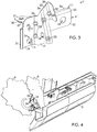
- a first element in this case a hubcap 3 rocker is reported on the interface 7.
- Two staples 8 have previously been pre-positioned on the hubcap 3 rocker.
- the embellisher 3 sill is snapped onto the first portion 9 of the interface 7 as illustrated on the figure 4 .
- a second body element namely the mudguard 5 is attached to the interface 7.
- An anchor (not shown) mounted in the mudguard is placed opposite the notch 18 made in the second part 10 and a screw (not shown) makes it possible to secure it to the interface 7.
- a third body element namely the wing 4 is attached to the interface 7.
- a screw (not shown) is inserted into the nut 30 and the wing 4 is fixed to the third portion 11.
- the interface attachment system 7 has several advantages.
- a first advantage is that the attachment is easy because several body elements 3, 4, 5 are fixed on one and the same piece.
- a second advantage is that the appearance of the body is substantially identical from one vehicle to another, the attachment to a single piece to avoid errors in dimensions related to manufacturing defects.
- a third advantage provided is that, in view of the fact that the interface is partly cantilevered, this avoids the rocker cover to be cantilevered beyond the fixation way too important. This reduces the risk of damage to the trim 3 rocker.
Landscapes
- Engineering & Computer Science (AREA)
- Chemical & Material Sciences (AREA)
- Combustion & Propulsion (AREA)
- Transportation (AREA)
- Mechanical Engineering (AREA)
- Body Structure For Vehicles (AREA)
- Vehicle Interior And Exterior Ornaments, Soundproofing, And Insulation (AREA)
Claims (10)
- System (2) zur Befestigung von Karosserieelementen (3, 4, 5) auf einem Kraftfahrzeugaufbau (6), wobei dieses Befestigungssystem (2) eine Schnittfläche (7) umfasst, die die Form eines einstückigen Teils hat und fest mit dem Kraftfahrzeugaufbau (6) verbunden ist, dadurch gekennzeichnet, dass diese Schnittfläche (7) Folgendes umfasst:- einen ersten Teil (9), der Befestigungsmittel umfasst, die dazu bestimmt sind, eine Aufbauunterseiten-Zierleiste (3) zu erhalten;- einen zweiten Teil (10), der Befestigungsmittel umfasst, die dazu bestimmt sind, einen Kotflügel (5) auf zunehmen;- einen dritten Teil (11), der Befestigungsmittel umfasst, die dazu bestimmt sind, einen vorderen Flügel (4) aufzunehmen.
- Befestigungssystem nach Anspruch 1, dadurch gekennzeichnet, dass sich der erste Teil (9), der zweite Teil (10) und der dritte Teil (11) jeweils in Ebenen, die zu je zwei im Wesentlichen zueinander senkrecht sind, erstrecken.
- Befestigungssystem (2) nach einem der vorhergehenden Ansprüche, dadurch gekennzeichnet, dass der erste Teil (9) eine erste Platte (12) und eine zweite Platte (13) umfasst, wobei diese Letzteren voneinander durch eine Stauplatte (16) beabstandet sind.
- Befestigungssystem (2) nach Anspruch 3, dadurch gekennzeichnet, dass der zweite Teil (10) eine dritte Platte (17) umfasst, wobei der zweite Teil (10) und der erste Teil (9) durch einen Verbindungsabschnitt (19) verbunden sind, der der zweiten Platte (13) gegenüber liegt, wobei der Verbindungsabschnitt (19) und der erste Teil (9) an ihrem Stoß einen Wulst (21), der durch Falten des Materials gebildet wird, aufweisen.
- Befestigungssystem (2) nach Anspruch 4, dadurch gekennzeichnet, dass der zweite Teil (10) und der Verbindungsabschnitt (19) an ihrem Stoß eine erste Kurve (22) aufweisen, auf der zwei Bulldozer (23) durch Stanzen des Materials gebildet sind.
- Befestigungssystem nach einem der vorhergehenden Ansprüche, dadurch gekennzeichnet, dass sich der dritte Teil (11) auskragend oberhalb des ersten Teils (9), mit dem er durch eine gewölbte Verbindung (25) verbunden ist, erstreckt.
- Befestigungssystem (2) nach einem der Ansprüche 3 bis 6, dadurch gekennzeichnet, dass der dritte Teil (11) eine vierte Platte (26) und eine fünfte Platte (27) umfasst, die sich jeweils auskragend oberhalb der ersten Platte (12) und der zweiten Platte (13) erstrecken.
- Befestigungssystem (2) nach einem der vorhergehenden Ansprüche, dadurch gekennzeichnet, dass die Schnittfläche (7) eine Befestigungspratze (32) umfasst, die mit dem zweiten Teil (10) durch einen Verbindungsabschnitt (33) verbunden ist, wobei der Verbindungsabschnitt (33) an einem seiner Enden mit dem zweiten Teil (10) durch eine erste Wölbung (34) und an dem anderen seiner Enden mit der Befestigungspratze (32) durch eine zweite Wölbung (35) verbunden ist.
- Befestigungssystem (2) nach einem der Ansprüche 7 bis 8, dadurch gekennzeichnet, dass die vierte Platte (26) und die fünfte Platte (27) voneinander durch einen gewölbten Abschnitt (28) beabstandet sind, wobei sich der gewölbte Abschnitt (28) auskragend auf der gesamten Länge der Stauplatte (16) erstreckt.
- Kraftfahrzeug (1), das ein Befestigungssystem nach einem der vorhergehenden Ansprüche umfasst.
Applications Claiming Priority (2)
| Application Number | Priority Date | Filing Date | Title |
|---|---|---|---|
| FR1451818A FR3018257B1 (fr) | 2014-03-06 | 2014-03-06 | Systeme de fixation de plusieurs elements de carrosserie |
| PCT/FR2015/050295 WO2015132490A1 (fr) | 2014-03-06 | 2015-02-06 | Système de fixation de plusieurs éléments de carrosserie |
Publications (2)
| Publication Number | Publication Date |
|---|---|
| EP3114014A1 EP3114014A1 (de) | 2017-01-11 |
| EP3114014B1 true EP3114014B1 (de) | 2018-01-10 |
Family
ID=50933327
Family Applications (1)
| Application Number | Title | Priority Date | Filing Date |
|---|---|---|---|
| EP15709225.5A Not-in-force EP3114014B1 (de) | 2014-03-06 | 2015-02-06 | System zur befestigung einer vielzahl von karosserieelementen |
Country Status (4)
| Country | Link |
|---|---|
| EP (1) | EP3114014B1 (de) |
| CN (1) | CN106103252B (de) |
| FR (1) | FR3018257B1 (de) |
| WO (1) | WO2015132490A1 (de) |
Families Citing this family (3)
| Publication number | Priority date | Publication date | Assignee | Title |
|---|---|---|---|---|
| FR3047963B1 (fr) * | 2016-02-18 | 2020-11-06 | Peugeot Citroen Automobiles Sa | Dispositif de fixation d'un garde-boue sur la caisse d'un vehicule automobile |
| FR3086918B1 (fr) * | 2018-10-03 | 2022-05-27 | Psa Automobiles Sa | Vehicule presentant au moins un support inferieur d’aile multifonction |
| FR3104537B1 (fr) | 2019-12-12 | 2022-01-07 | Psa Automobiles Sa | Interface de fixation monobloc entre une pluralité d'éléments de carrosserie et un pied de porte avant que comporte une caisse de véhicule automobile. |
Family Cites Families (15)
| Publication number | Priority date | Publication date | Assignee | Title |
|---|---|---|---|---|
| JPS5839965Y2 (ja) * | 1979-03-01 | 1983-09-08 | 日産自動車株式会社 | 自動車のフエンダ構造 |
| JPS58136571A (ja) * | 1982-02-09 | 1983-08-13 | Nissan Motor Co Ltd | 自動車の車体構造 |
| JPS58218477A (ja) * | 1982-06-14 | 1983-12-19 | Nissan Motor Co Ltd | フエンダプロテクタ構造 |
| DE3315341A1 (de) * | 1983-04-28 | 1984-10-31 | Knut 2000 Hamburg Arenhold | Vorrichtung zur befestigung eines schmutzfaengers am kotfluegelfalz eines kraftfahrzeugs |
| DE102005006306A1 (de) * | 2005-02-11 | 2006-08-17 | Rehau Ag + Co | Bausatz für die Montage eines Fahrzeugverkleidungselements |
| DE102005041216A1 (de) * | 2005-08-31 | 2007-03-15 | Daimlerchrysler Ag | Befestigungsanordnung von Außenbeplankungsteilen eines Kraftwagens |
| DE602005023501D1 (de) * | 2005-12-16 | 2010-10-21 | Ford Global Tech Llc | Radhausbau |
| CN201068168Y (zh) * | 2007-07-31 | 2008-06-04 | 重庆长安汽车股份有限公司 | 一种汽车翼子板保险杠一体安装托架 |
| FR2924085B1 (fr) * | 2007-11-23 | 2010-06-18 | Peugeot Citroen Automobiles Sa | Dispositif et procede de fixation d'un ensemble d'aile sur une paroi de caisse d'un vehicule automobile |
| FR2930925B1 (fr) * | 2008-05-06 | 2010-04-23 | Renault Sas | Support de fixation d'un element d'habillage d'une partie de carrosserie d'un vehicule, element d'habillage correspondant et utilisation d'un tel support de fixation |
| JP4688915B2 (ja) * | 2008-09-29 | 2011-05-25 | 株式会社ホンダアクセス | サイドアンダースポイラー取付構造 |
| CN101659277B (zh) * | 2009-09-25 | 2011-08-24 | 江苏汤臣汽车零部件有限公司 | 一种载重汽车底盘整体支架支承座 |
| CN101863288B (zh) * | 2010-06-28 | 2011-12-21 | 重庆长安汽车股份有限公司 | 一种汽车前轮罩侧板总成 |
| CN102390338A (zh) * | 2011-09-30 | 2012-03-28 | 重庆长安汽车股份有限公司 | 一种汽车保险杠侧安装支架与翼子板的连接结构 |
| FR2990403B1 (fr) * | 2012-05-09 | 2014-05-16 | Peugeot Citroen Automobiles Sa | Dispositif de fixation renforcee d'une aile sur une paroi de caisse |
-
2014
- 2014-03-06 FR FR1451818A patent/FR3018257B1/fr active Active
-
2015
- 2015-02-06 EP EP15709225.5A patent/EP3114014B1/de not_active Not-in-force
- 2015-02-06 CN CN201580012388.XA patent/CN106103252B/zh not_active Expired - Fee Related
- 2015-02-06 WO PCT/FR2015/050295 patent/WO2015132490A1/fr not_active Ceased
Also Published As
| Publication number | Publication date |
|---|---|
| EP3114014A1 (de) | 2017-01-11 |
| CN106103252A (zh) | 2016-11-09 |
| FR3018257A1 (fr) | 2015-09-11 |
| FR3018257B1 (fr) | 2016-04-01 |
| CN106103252B (zh) | 2019-08-02 |
| WO2015132490A1 (fr) | 2015-09-11 |
Similar Documents
| Publication | Publication Date | Title |
|---|---|---|
| EP2914476B1 (de) | Vorrichtung zur befestigung zweier bauteile aneinander mit einem gleitenden positionierungselement | |
| EP3114014B1 (de) | System zur befestigung einer vielzahl von karosserieelementen | |
| FR2957047A1 (fr) | Structure de carrosserie brute d'un vehicule automobile leger avec module de bequet arriere | |
| EP2062804B1 (de) | Vorrichtung und Verfahren zur Befestigung einer Kotflügeleinheit an der Wagenkastenwand eines Kraftfahrzeugs | |
| WO2009001016A2 (fr) | Articulation d'un capot de vehicule automobile | |
| EP1101691B1 (de) | Vorder- Viertel- Befestigung auf Querträger | |
| EP2925565B1 (de) | Dachstruktur für ein kraftfahrzeug | |
| EP2436580A2 (de) | Aerodynamische Baugruppe für Heckklappe eines Kraftfahrzeugs | |
| EP3050758B1 (de) | Strukturelle untereinheit eines kraftfahrzeugs, und montageverfahren dieses unterelements | |
| FR2921040A1 (fr) | Procede d'assemblage d'une peau de pare-chocs sur une caisse de vehicule automobile. | |
| FR3139783A1 (fr) | extension de longeronnet arrière pour véhicule automobile | |
| FR3136720A1 (fr) | Support latéral pour l’assemblage d’une peau de parechoc et d’un pare-boue. | |
| FR3139774A1 (fr) | Enjoliveur latéral pour pare-chocs de véhicule automobile, pare-chocs de véhicule automobile comportant un tel enjoliveur latéral et véhicule automobile comportant un tel pare-chocs | |
| EP3405382B1 (de) | Teil zur verstärkung eines unteren querträgers für eine fensteröffnung | |
| FR2868371A1 (fr) | Ensemble de montage d'une barre de toit longitudinale sur un toit d'un vehicule automobile | |
| FR3100772A1 (fr) | aménagement de parechoc pour véhicule automobile | |
| EP1610005B1 (de) | Klammer für die Befestigung einer Schraube an Teile eines Automobils | |
| EP3860903B1 (de) | Unterer vorderflügelträger zur bereitstellung der funktion der kopplung von 3 verschiedenen teilen | |
| FR2889832A1 (fr) | Dispositif de fixation d'une aile de vehicule automobile | |
| FR3062367B1 (fr) | Traverse de planche de bord et console de support de colonne de direction modulaires | |
| WO2015018991A1 (fr) | Procede de montage d'un poste de conduite sur une caisse de vehicule automobile et ensemble de montage correspondant | |
| FR3102538A1 (fr) | Ensemble de feu arrière de véhicule automobile | |
| FR3161192A1 (fr) | Déflecteur pour véhicule automobile et véhicule comprenant un tel déflecteur | |
| FR2801032A1 (fr) | Fixation quart avant sur traverse | |
| EP4077104A1 (de) | Strukturregal für ein kraftfahrzeug |
Legal Events
| Date | Code | Title | Description |
|---|---|---|---|
| PUAI | Public reference made under article 153(3) epc to a published international application that has entered the european phase |
Free format text: ORIGINAL CODE: 0009012 |
|
| STAA | Information on the status of an ep patent application or granted ep patent |
Free format text: STATUS: REQUEST FOR EXAMINATION WAS MADE |
|
| 17P | Request for examination filed |
Effective date: 20160728 |
|
| AK | Designated contracting states |
Kind code of ref document: A1 Designated state(s): AL AT BE BG CH CY CZ DE DK EE ES FI FR GB GR HR HU IE IS IT LI LT LU LV MC MK MT NL NO PL PT RO RS SE SI SK SM TR |
|
| AX | Request for extension of the european patent |
Extension state: BA ME |
|
| DAX | Request for extension of the european patent (deleted) | ||
| GRAP | Despatch of communication of intention to grant a patent |
Free format text: ORIGINAL CODE: EPIDOSNIGR1 |
|
| STAA | Information on the status of an ep patent application or granted ep patent |
Free format text: STATUS: GRANT OF PATENT IS INTENDED |
|
| INTG | Intention to grant announced |
Effective date: 20170803 |
|
| RAP1 | Party data changed (applicant data changed or rights of an application transferred) |
Owner name: PSA AUTOMOBILES SA |
|
| GRAS | Grant fee paid |
Free format text: ORIGINAL CODE: EPIDOSNIGR3 |
|
| GRAA | (expected) grant |
Free format text: ORIGINAL CODE: 0009210 |
|
| STAA | Information on the status of an ep patent application or granted ep patent |
Free format text: STATUS: THE PATENT HAS BEEN GRANTED |
|
| AK | Designated contracting states |
Kind code of ref document: B1 Designated state(s): AL AT BE BG CH CY CZ DE DK EE ES FI FR GB GR HR HU IE IS IT LI LT LU LV MC MK MT NL NO PL PT RO RS SE SI SK SM TR |
|
| REG | Reference to a national code |
Ref country code: CH Ref legal event code: EP Ref country code: AT Ref legal event code: REF Ref document number: 962065 Country of ref document: AT Kind code of ref document: T Effective date: 20180115 |
|
| REG | Reference to a national code |
Ref country code: DE Ref legal event code: R084 Ref document number: 602015007356 Country of ref document: DE |
|
| REG | Reference to a national code |
Ref country code: IE Ref legal event code: FG4D Free format text: LANGUAGE OF EP DOCUMENT: FRENCH |
|
| REG | Reference to a national code |
Ref country code: DE Ref legal event code: R096 Ref document number: 602015007356 Country of ref document: DE |
|
| REG | Reference to a national code |
Ref country code: FR Ref legal event code: PLFP Year of fee payment: 4 |
|
| REG | Reference to a national code |
Ref country code: GB Ref legal event code: 746 Effective date: 20180202 |
|
| REG | Reference to a national code |
Ref country code: NL Ref legal event code: MP Effective date: 20180110 |
|
| REG | Reference to a national code |
Ref country code: AT Ref legal event code: MK05 Ref document number: 962065 Country of ref document: AT Kind code of ref document: T Effective date: 20180110 |
|
| PG25 | Lapsed in a contracting state [announced via postgrant information from national office to epo] |
Ref country code: NL Free format text: LAPSE BECAUSE OF FAILURE TO SUBMIT A TRANSLATION OF THE DESCRIPTION OR TO PAY THE FEE WITHIN THE PRESCRIBED TIME-LIMIT Effective date: 20180110 |
|
| PG25 | Lapsed in a contracting state [announced via postgrant information from national office to epo] |
Ref country code: ES Free format text: LAPSE BECAUSE OF FAILURE TO SUBMIT A TRANSLATION OF THE DESCRIPTION OR TO PAY THE FEE WITHIN THE PRESCRIBED TIME-LIMIT Effective date: 20180110 Ref country code: HR Free format text: LAPSE BECAUSE OF FAILURE TO SUBMIT A TRANSLATION OF THE DESCRIPTION OR TO PAY THE FEE WITHIN THE PRESCRIBED TIME-LIMIT Effective date: 20180110 Ref country code: LT Free format text: LAPSE BECAUSE OF FAILURE TO SUBMIT A TRANSLATION OF THE DESCRIPTION OR TO PAY THE FEE WITHIN THE PRESCRIBED TIME-LIMIT Effective date: 20180110 Ref country code: NO Free format text: LAPSE BECAUSE OF FAILURE TO SUBMIT A TRANSLATION OF THE DESCRIPTION OR TO PAY THE FEE WITHIN THE PRESCRIBED TIME-LIMIT Effective date: 20180410 Ref country code: CY Free format text: LAPSE BECAUSE OF FAILURE TO SUBMIT A TRANSLATION OF THE DESCRIPTION OR TO PAY THE FEE WITHIN THE PRESCRIBED TIME-LIMIT Effective date: 20180110 Ref country code: FI Free format text: LAPSE BECAUSE OF FAILURE TO SUBMIT A TRANSLATION OF THE DESCRIPTION OR TO PAY THE FEE WITHIN THE PRESCRIBED TIME-LIMIT Effective date: 20180110 |
|
| PG25 | Lapsed in a contracting state [announced via postgrant information from national office to epo] |
Ref country code: IS Free format text: LAPSE BECAUSE OF FAILURE TO SUBMIT A TRANSLATION OF THE DESCRIPTION OR TO PAY THE FEE WITHIN THE PRESCRIBED TIME-LIMIT Effective date: 20180510 Ref country code: GR Free format text: LAPSE BECAUSE OF FAILURE TO SUBMIT A TRANSLATION OF THE DESCRIPTION OR TO PAY THE FEE WITHIN THE PRESCRIBED TIME-LIMIT Effective date: 20180411 Ref country code: LV Free format text: LAPSE BECAUSE OF FAILURE TO SUBMIT A TRANSLATION OF THE DESCRIPTION OR TO PAY THE FEE WITHIN THE PRESCRIBED TIME-LIMIT Effective date: 20180110 Ref country code: PL Free format text: LAPSE BECAUSE OF FAILURE TO SUBMIT A TRANSLATION OF THE DESCRIPTION OR TO PAY THE FEE WITHIN THE PRESCRIBED TIME-LIMIT Effective date: 20180110 Ref country code: RS Free format text: LAPSE BECAUSE OF FAILURE TO SUBMIT A TRANSLATION OF THE DESCRIPTION OR TO PAY THE FEE WITHIN THE PRESCRIBED TIME-LIMIT Effective date: 20180110 Ref country code: SE Free format text: LAPSE BECAUSE OF FAILURE TO SUBMIT A TRANSLATION OF THE DESCRIPTION OR TO PAY THE FEE WITHIN THE PRESCRIBED TIME-LIMIT Effective date: 20180110 Ref country code: BG Free format text: LAPSE BECAUSE OF FAILURE TO SUBMIT A TRANSLATION OF THE DESCRIPTION OR TO PAY THE FEE WITHIN THE PRESCRIBED TIME-LIMIT Effective date: 20180410 Ref country code: AT Free format text: LAPSE BECAUSE OF FAILURE TO SUBMIT A TRANSLATION OF THE DESCRIPTION OR TO PAY THE FEE WITHIN THE PRESCRIBED TIME-LIMIT Effective date: 20180110 |
|
| REG | Reference to a national code |
Ref country code: CH Ref legal event code: PL |
|
| PG25 | Lapsed in a contracting state [announced via postgrant information from national office to epo] |
Ref country code: MT Free format text: LAPSE BECAUSE OF FAILURE TO SUBMIT A TRANSLATION OF THE DESCRIPTION OR TO PAY THE FEE WITHIN THE PRESCRIBED TIME-LIMIT Effective date: 20180110 |
|
| REG | Reference to a national code |
Ref country code: DE Ref legal event code: R097 Ref document number: 602015007356 Country of ref document: DE |
|
| PG25 | Lapsed in a contracting state [announced via postgrant information from national office to epo] |
Ref country code: IT Free format text: LAPSE BECAUSE OF FAILURE TO SUBMIT A TRANSLATION OF THE DESCRIPTION OR TO PAY THE FEE WITHIN THE PRESCRIBED TIME-LIMIT Effective date: 20180110 Ref country code: AL Free format text: LAPSE BECAUSE OF FAILURE TO SUBMIT A TRANSLATION OF THE DESCRIPTION OR TO PAY THE FEE WITHIN THE PRESCRIBED TIME-LIMIT Effective date: 20180110 Ref country code: MC Free format text: LAPSE BECAUSE OF FAILURE TO SUBMIT A TRANSLATION OF THE DESCRIPTION OR TO PAY THE FEE WITHIN THE PRESCRIBED TIME-LIMIT Effective date: 20180110 Ref country code: EE Free format text: LAPSE BECAUSE OF FAILURE TO SUBMIT A TRANSLATION OF THE DESCRIPTION OR TO PAY THE FEE WITHIN THE PRESCRIBED TIME-LIMIT Effective date: 20180110 |
|
| PLBE | No opposition filed within time limit |
Free format text: ORIGINAL CODE: 0009261 |
|
| STAA | Information on the status of an ep patent application or granted ep patent |
Free format text: STATUS: NO OPPOSITION FILED WITHIN TIME LIMIT |
|
| REG | Reference to a national code |
Ref country code: IE Ref legal event code: MM4A |
|
| REG | Reference to a national code |
Ref country code: BE Ref legal event code: MM Effective date: 20180228 |
|
| PG25 | Lapsed in a contracting state [announced via postgrant information from national office to epo] |
Ref country code: DK Free format text: LAPSE BECAUSE OF FAILURE TO SUBMIT A TRANSLATION OF THE DESCRIPTION OR TO PAY THE FEE WITHIN THE PRESCRIBED TIME-LIMIT Effective date: 20180110 Ref country code: LI Free format text: LAPSE BECAUSE OF NON-PAYMENT OF DUE FEES Effective date: 20180228 Ref country code: CH Free format text: LAPSE BECAUSE OF NON-PAYMENT OF DUE FEES Effective date: 20180228 Ref country code: CZ Free format text: LAPSE BECAUSE OF FAILURE TO SUBMIT A TRANSLATION OF THE DESCRIPTION OR TO PAY THE FEE WITHIN THE PRESCRIBED TIME-LIMIT Effective date: 20180110 Ref country code: SK Free format text: LAPSE BECAUSE OF FAILURE TO SUBMIT A TRANSLATION OF THE DESCRIPTION OR TO PAY THE FEE WITHIN THE PRESCRIBED TIME-LIMIT Effective date: 20180110 Ref country code: SM Free format text: LAPSE BECAUSE OF FAILURE TO SUBMIT A TRANSLATION OF THE DESCRIPTION OR TO PAY THE FEE WITHIN THE PRESCRIBED TIME-LIMIT Effective date: 20180110 Ref country code: LU Free format text: LAPSE BECAUSE OF NON-PAYMENT OF DUE FEES Effective date: 20180206 |
|
| 26N | No opposition filed |
Effective date: 20181011 |
|
| PG25 | Lapsed in a contracting state [announced via postgrant information from national office to epo] |
Ref country code: IE Free format text: LAPSE BECAUSE OF NON-PAYMENT OF DUE FEES Effective date: 20180206 |
|
| PG25 | Lapsed in a contracting state [announced via postgrant information from national office to epo] |
Ref country code: BE Free format text: LAPSE BECAUSE OF NON-PAYMENT OF DUE FEES Effective date: 20180228 Ref country code: SI Free format text: LAPSE BECAUSE OF FAILURE TO SUBMIT A TRANSLATION OF THE DESCRIPTION OR TO PAY THE FEE WITHIN THE PRESCRIBED TIME-LIMIT Effective date: 20180110 |
|
| PG25 | Lapsed in a contracting state [announced via postgrant information from national office to epo] |
Ref country code: TR Free format text: LAPSE BECAUSE OF FAILURE TO SUBMIT A TRANSLATION OF THE DESCRIPTION OR TO PAY THE FEE WITHIN THE PRESCRIBED TIME-LIMIT Effective date: 20180110 |
|
| PG25 | Lapsed in a contracting state [announced via postgrant information from national office to epo] |
Ref country code: PT Free format text: LAPSE BECAUSE OF FAILURE TO SUBMIT A TRANSLATION OF THE DESCRIPTION OR TO PAY THE FEE WITHIN THE PRESCRIBED TIME-LIMIT Effective date: 20180110 |
|
| PG25 | Lapsed in a contracting state [announced via postgrant information from national office to epo] |
Ref country code: HU Free format text: LAPSE BECAUSE OF FAILURE TO SUBMIT A TRANSLATION OF THE DESCRIPTION OR TO PAY THE FEE WITHIN THE PRESCRIBED TIME-LIMIT; INVALID AB INITIO Effective date: 20150206 Ref country code: MK Free format text: LAPSE BECAUSE OF NON-PAYMENT OF DUE FEES Effective date: 20180110 Ref country code: RO Free format text: LAPSE BECAUSE OF FAILURE TO SUBMIT A TRANSLATION OF THE DESCRIPTION OR TO PAY THE FEE WITHIN THE PRESCRIBED TIME-LIMIT Effective date: 20180110 |
|
| PGFP | Annual fee paid to national office [announced via postgrant information from national office to epo] |
Ref country code: GB Payment date: 20220119 Year of fee payment: 8 Ref country code: DE Payment date: 20220119 Year of fee payment: 8 |
|
| PGFP | Annual fee paid to national office [announced via postgrant information from national office to epo] |
Ref country code: FR Payment date: 20220119 Year of fee payment: 8 |
|
| REG | Reference to a national code |
Ref country code: DE Ref legal event code: R119 Ref document number: 602015007356 Country of ref document: DE |
|
| GBPC | Gb: european patent ceased through non-payment of renewal fee |
Effective date: 20230206 |
|
| PG25 | Lapsed in a contracting state [announced via postgrant information from national office to epo] |
Ref country code: GB Free format text: LAPSE BECAUSE OF NON-PAYMENT OF DUE FEES Effective date: 20230206 |
|
| PG25 | Lapsed in a contracting state [announced via postgrant information from national office to epo] |
Ref country code: GB Free format text: LAPSE BECAUSE OF NON-PAYMENT OF DUE FEES Effective date: 20230206 Ref country code: FR Free format text: LAPSE BECAUSE OF NON-PAYMENT OF DUE FEES Effective date: 20230228 Ref country code: DE Free format text: LAPSE BECAUSE OF NON-PAYMENT OF DUE FEES Effective date: 20230901 |