EP3114351B1 - Pompe à liquide électrique pour automobile - Google Patents
Pompe à liquide électrique pour automobile Download PDFInfo
- Publication number
- EP3114351B1 EP3114351B1 EP14708535.1A EP14708535A EP3114351B1 EP 3114351 B1 EP3114351 B1 EP 3114351B1 EP 14708535 A EP14708535 A EP 14708535A EP 3114351 B1 EP3114351 B1 EP 3114351B1
- Authority
- EP
- European Patent Office
- Prior art keywords
- rotor
- liquid pump
- electric liquid
- pump
- automotive electric
- Prior art date
- Legal status (The legal status is an assumption and is not a legal conclusion. Google has not performed a legal analysis and makes no representation as to the accuracy of the status listed.)
- Active
Links
Images
Classifications
-
- F—MECHANICAL ENGINEERING; LIGHTING; HEATING; WEAPONS; BLASTING
- F04—POSITIVE - DISPLACEMENT MACHINES FOR LIQUIDS; PUMPS FOR LIQUIDS OR ELASTIC FLUIDS
- F04D—NON-POSITIVE-DISPLACEMENT PUMPS
- F04D13/00—Pumping installations or systems
- F04D13/02—Units comprising pumps and their driving means
- F04D13/06—Units comprising pumps and their driving means the pump being electrically driven
- F04D13/0606—Canned motor pumps
- F04D13/0633—Details of the bearings
-
- F—MECHANICAL ENGINEERING; LIGHTING; HEATING; WEAPONS; BLASTING
- F01—MACHINES OR ENGINES IN GENERAL; ENGINE PLANTS IN GENERAL; STEAM ENGINES
- F01M—LUBRICATING OF MACHINES OR ENGINES IN GENERAL; LUBRICATING INTERNAL COMBUSTION ENGINES; CRANKCASE VENTILATING
- F01M1/00—Pressure lubrication
- F01M1/02—Pressure lubrication using lubricating pumps
-
- F—MECHANICAL ENGINEERING; LIGHTING; HEATING; WEAPONS; BLASTING
- F01—MACHINES OR ENGINES IN GENERAL; ENGINE PLANTS IN GENERAL; STEAM ENGINES
- F01P—COOLING OF MACHINES OR ENGINES IN GENERAL; COOLING OF INTERNAL-COMBUSTION ENGINES
- F01P5/00—Pumping cooling-air or liquid coolants
- F01P5/10—Pumping liquid coolant; Arrangements of coolant pumps
- F01P5/12—Pump-driving arrangements
-
- F—MECHANICAL ENGINEERING; LIGHTING; HEATING; WEAPONS; BLASTING
- F04—POSITIVE - DISPLACEMENT MACHINES FOR LIQUIDS; PUMPS FOR LIQUIDS OR ELASTIC FLUIDS
- F04D—NON-POSITIVE-DISPLACEMENT PUMPS
- F04D1/00—Radial-flow pumps, e.g. centrifugal pumps; Helico-centrifugal pumps
-
- F—MECHANICAL ENGINEERING; LIGHTING; HEATING; WEAPONS; BLASTING
- F04—POSITIVE - DISPLACEMENT MACHINES FOR LIQUIDS; PUMPS FOR LIQUIDS OR ELASTIC FLUIDS
- F04D—NON-POSITIVE-DISPLACEMENT PUMPS
- F04D15/00—Control, e.g. regulation, of pumps, pumping installations or systems
-
- F—MECHANICAL ENGINEERING; LIGHTING; HEATING; WEAPONS; BLASTING
- F04—POSITIVE - DISPLACEMENT MACHINES FOR LIQUIDS; PUMPS FOR LIQUIDS OR ELASTIC FLUIDS
- F04D—NON-POSITIVE-DISPLACEMENT PUMPS
- F04D29/00—Details, component parts, or accessories
- F04D29/04—Shafts or bearings, or assemblies thereof
- F04D29/041—Axial thrust balancing
- F04D29/0413—Axial thrust balancing hydrostatic; hydrodynamic thrust bearings
-
- F—MECHANICAL ENGINEERING; LIGHTING; HEATING; WEAPONS; BLASTING
- F04—POSITIVE - DISPLACEMENT MACHINES FOR LIQUIDS; PUMPS FOR LIQUIDS OR ELASTIC FLUIDS
- F04D—NON-POSITIVE-DISPLACEMENT PUMPS
- F04D29/00—Details, component parts, or accessories
- F04D29/04—Shafts or bearings, or assemblies thereof
- F04D29/043—Shafts
-
- F—MECHANICAL ENGINEERING; LIGHTING; HEATING; WEAPONS; BLASTING
- F04—POSITIVE - DISPLACEMENT MACHINES FOR LIQUIDS; PUMPS FOR LIQUIDS OR ELASTIC FLUIDS
- F04D—NON-POSITIVE-DISPLACEMENT PUMPS
- F04D29/00—Details, component parts, or accessories
- F04D29/04—Shafts or bearings, or assemblies thereof
- F04D29/046—Bearings
-
- F—MECHANICAL ENGINEERING; LIGHTING; HEATING; WEAPONS; BLASTING
- F04—POSITIVE - DISPLACEMENT MACHINES FOR LIQUIDS; PUMPS FOR LIQUIDS OR ELASTIC FLUIDS
- F04D—NON-POSITIVE-DISPLACEMENT PUMPS
- F04D29/00—Details, component parts, or accessories
- F04D29/04—Shafts or bearings, or assemblies thereof
- F04D29/046—Bearings
- F04D29/047—Bearings hydrostatic; hydrodynamic
- F04D29/0473—Bearings hydrostatic; hydrodynamic for radial pumps
-
- F—MECHANICAL ENGINEERING; LIGHTING; HEATING; WEAPONS; BLASTING
- F04—POSITIVE - DISPLACEMENT MACHINES FOR LIQUIDS; PUMPS FOR LIQUIDS OR ELASTIC FLUIDS
- F04D—NON-POSITIVE-DISPLACEMENT PUMPS
- F04D29/00—Details, component parts, or accessories
- F04D29/18—Rotors
- F04D29/22—Rotors specially for centrifugal pumps
-
- F—MECHANICAL ENGINEERING; LIGHTING; HEATING; WEAPONS; BLASTING
- F01—MACHINES OR ENGINES IN GENERAL; ENGINE PLANTS IN GENERAL; STEAM ENGINES
- F01M—LUBRICATING OF MACHINES OR ENGINES IN GENERAL; LUBRICATING INTERNAL COMBUSTION ENGINES; CRANKCASE VENTILATING
- F01M1/00—Pressure lubrication
- F01M1/02—Pressure lubrication using lubricating pumps
- F01M2001/0207—Pressure lubrication using lubricating pumps characterised by the type of pump
- F01M2001/0215—Electrical pumps
-
- F—MECHANICAL ENGINEERING; LIGHTING; HEATING; WEAPONS; BLASTING
- F01—MACHINES OR ENGINES IN GENERAL; ENGINE PLANTS IN GENERAL; STEAM ENGINES
- F01M—LUBRICATING OF MACHINES OR ENGINES IN GENERAL; LUBRICATING INTERNAL COMBUSTION ENGINES; CRANKCASE VENTILATING
- F01M1/00—Pressure lubrication
- F01M1/02—Pressure lubrication using lubricating pumps
- F01M2001/0207—Pressure lubrication using lubricating pumps characterised by the type of pump
- F01M2001/0238—Rotary pumps
-
- F—MECHANICAL ENGINEERING; LIGHTING; HEATING; WEAPONS; BLASTING
- F01—MACHINES OR ENGINES IN GENERAL; ENGINE PLANTS IN GENERAL; STEAM ENGINES
- F01P—COOLING OF MACHINES OR ENGINES IN GENERAL; COOLING OF INTERNAL-COMBUSTION ENGINES
- F01P5/00—Pumping cooling-air or liquid coolants
- F01P5/10—Pumping liquid coolant; Arrangements of coolant pumps
- F01P5/12—Pump-driving arrangements
- F01P2005/125—Driving auxiliary pumps electrically
-
- F—MECHANICAL ENGINEERING; LIGHTING; HEATING; WEAPONS; BLASTING
- F04—POSITIVE - DISPLACEMENT MACHINES FOR LIQUIDS; PUMPS FOR LIQUIDS OR ELASTIC FLUIDS
- F04D—NON-POSITIVE-DISPLACEMENT PUMPS
- F04D13/00—Pumping installations or systems
- F04D13/02—Units comprising pumps and their driving means
- F04D13/06—Units comprising pumps and their driving means the pump being electrically driven
- F04D13/0646—Units comprising pumps and their driving means the pump being electrically driven the hollow pump or motor shaft being the conduit for the working fluid
Definitions
- the invention refers to an automotive electric liquid pump, for example to an electric coolant or lubricant pump.
- Conventional automotive electric liquid pumps are provided with a rotor shaft co-rotatably supporting a motor rotor and a pump rotor.
- the pump rotor can be part of a positive displacement pump or of a flow pump.
- the rotor shaft is rotatably supported with two separate roller or slide bearings which are arranged at one free end of the rotor shaft and between the motor rotor and the pump rotor.
- the automotive electric liquid pump according to the invention is provided with a pump rotor and a motor rotor, both co-rotatably supported by a rotor shaft.
- the electric motor of the pump is provided as a so-called can motor.
- the motor rotor is rotating in a separation can which fluidically separates the wet motor rotor chamber from the dry part of the pump and in particular fluidically separates the motor rotor from the motor stator comprising electromagnetic stator coils.
- the radial outside of the motor rotor is provided with a cylindrical bearing ring and the radial inside of the separation can is provided with a corresponding static and cylindrical bearing ring.
- the cylindrical rotor bearing ring and the cylindrical static bearing ring together define a radial slide bearing.
- the radial slide bearing is arranged within the axial extension of the motor rotor and is not arranged axially outside of the motor rotor. Therefore, the total axial length of the pump can be reduced because one or even two bearings axially outside of the motor rotor can be avoided.
- the radial slide bearing is provided as a so-called plane bearing but is not provided as a floating support arrangement.
- the radial bearing gap G between the static bearing ring and the rotor bearing ring is small and allows a lubrication of the bearing within the bearing gap G with the coolant liquid or with the lubrication liquid.
- the liquid can be a coolant liquid for cooling an internal combustion engine or other automotive devices, can be a hydraulic liquid for hydraulic devices in an automotive vehicle or can be a lubricant for lubrication of an internal combustion engine or other automotive devices.
- the liquid is water, fuel or oil.
- the radial bearing gap G of the radial slide bearing is less than 0,5 mm, preferably is less than 0,25 mm.
- the radial bearing gap G has to be as small as possible to guarantee relatively small gaps of the pump rotor with respect to the pump housing to thereby guarantee a high hydraulic efficiency of the pump section of the pump.
- the radial bearing gap G has to be large enough to guarantee a sufficient lubrication of the bearing gap between the static bearing ring and the rotor bearing ring.
- At least two separate radial slide bearings are provided at the motor rotor and a corresponding number of static bearing rings are provided at the separation can.
- one separate radial slide bearing is provided at both axial ends of the motor rotor, respectively. This arrangement of the two radial slide bearings guarantees a maximum stability against tilting of the complete rotor arrangement and a minimum friction.
- a separate axial slide bearing is provided which is defined by an axial bearing ring at one axial end surface of the motor rotor and by a static bearing ring.
- the static bearing ring can be provided by a corresponding ring section of the pump frame or pump housing. Beside of the radial bearings also the axial bearing is provided as a slide bearing which does not need much installation space.
- the rotor shaft supporting the motor rotor and the pump rotor is provided with a continuous central cooling bore.
- the liquid pumped by the pump rotor is pushed through the cooling bore from the pump rotor end of the shaft to the other axial end of the shaft, from where the liquid is radially flowing outwardly and axially flowing back through the bearing gap back to the pump section.
- the liquid can circulate within the motor section of the pump to realize a continuous axial flow of the liquid through the bearing gap between the rotor bearing ring and that static bearing ring.
- the motor control electronics is provided in a control electronics chamber which is separated from the motor rotor rotating in the liquid by a single transversal separation wall.
- the liquid flowing through the shaft bore impinges against the transversal separation wall so that the separation wall is continuously cooled by the liquid radially flowing from the axial center to the outside where the liquid axially flows into the radial bearing gap. Therefore, the secondary liquid circuit defined by the shaft cooling bore and the radial bearing gap has a double function, i.e. cooling of the separation wall and lubrication of the bearing gap.
- the electronics, and in particular the power semiconductors are provided in heat-conductive contact with the separation wall, for example by using a heat-conductive adhesive.
- the rotor bearing ring is made out of metal.
- the rotor bearing ring it can be defined by the motor rotor itself and, for example, can be a polished section of the motor rotor.
- the static bearing ring is made of plastic, and preferably is made of PTFE (polytetrafluoroethylene) or PA (polyamide).
- PTFE polytetrafluoroethylene
- PA polyamide
- a circular ring groove is provided at the radial inside of the separation can between the two static bearing rings.
- the ring groove separates the two static bearings rings from each other.
- the axial length of the ring groove preferably is identical with the axial distance of the corresponding static bearings rings.
- the ring groove provides a very low fluidic resistance in a section where no narrow gap is needed and thereby reduces the total axial flow resistance in the bearing gap over the entire length of the motor rotor.
- a longitudinal flow groove is provided at the radial inside of the separation can.
- the longitudinal flow groove can be orientated precisely axially.
- the longitudinal flow groove can, for example, have a helical orientation with a substantive axial component.
- the longitudinal flow groove improves the lubrication of the radial slide bearings because the liquid can flow into the bearing gap also from a circumferential/tangential direction coming from the longitudinal flow groove, not only from an axial direction as it would be without a longitudinal flow groove.
- the longitudinal flow groove reduces the total axial flow resistance.
- two or even more longitudinal flow grooves can be provided.
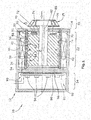
- the figure shows an electric automotive liquid pump 10 which is configured as a flow pump, for example as a coolant pump or as a fuel pump.
- the liquid pump 10 can alternatively also be realized as a positive displacement pump, for example for pumping a lubricant for lubrication of an internal combustion engine.
- the liquid pump 10 is provided, seen in axial direction, with a pump section 20, a motor section 22 and a control section 24.
- the pump section 20 is provided with a pump rotor 21 which is, in this embodiment, an impeller wheel with an axial inlet opening.
- the pump rotor can alternatively be designed and provided as a part of a positive displacement pump, for example a gerotor pump, a vane pump or another rotating displacement pump.
- the pump rotor 21 is supported by a co-rotating the rotor shaft 80 which is co-rotatably fixed to the motor rotor 32.
- the motor rotor 32 is defined by a motor rotor body 38 made out of a ferromagnetic material and being permanently magnetized.
- the motor rotor 32 is magnetically driven by a motor stator which is defined by a number of motor stator coils 48 which generate a rotating magnetic field which is followed by the permanently magnetized motor rotor 32.
- the motor section 22 is designed as a canned motor with a cylindrical separation can 50 separating the wet motor rotor 32 from the dry motor stator coils 48.
- the separation 50 is defined by a cylindrical can body 51 made out of plastic.
- the control section 24 is defined by control electronics 90 arranged within a control electronics chamber 92.
- the control electronics 90 is defined by a printed circuit board 91 comprising power semiconductors 94 for electrically switching the stator coils 48.
- the control electronics chamber 92 is separated from the motor section 22 by a transversal separation wall 96.
- the printed circuit board 91 is fixed to and thermally connected to the separation wall 96 by a heat-conductive adhesive 98 or paste which is applied in particular opposite to the power semiconductors 94.
- the motor rotor 32 is rotatably supported by two radial slide bearings 61, 62 and by one axial slide bearing 70.
- the first radial slide bearing 61 is defined by a cylindrical static bearing ring 54 at the radial inside of the plastic separation can 50 and a corresponding cylindrical rotor bearing ring 34 at the radial outside of the motor rotor 32.
- the second radial slide bearing 62 is, as well, defined by a cylindrical static bearing ring 56 at the radial inside of the plastic separation can body 50 and a corresponding rotor bearing ring 36 at the radial outside of the motor rotor 32.
- the radial bearing gap G between the bearing surfaces 34,54;36,56 of both radial sliding bearings 61, 62 is about 0,1 mm.
- the rotor bearing rings 34, 36 are defined by the polished cylindrical surface of the motor rotor body 38 made out of ferromagnetic steel or of another ferromagnetic metal.
- the static bearings rings 54, 56 are defined by a cylindrical inner surface of the can body 51 which is made out of plastic, preferably made out of PTFE.
- the two radial slide bearings 61, 62 are axially separated by a circumferential ring groove 42 with a radial depth of more than 0,5 mm.
- the separation can 50 is also provided with two parallel longitudinal flow grooves 44 which axially overlap the two radial slide bearings 61, 62.
- the radial depth of the longitudinal flow grooves is more than 0,5 mm.
- the axial bearing 70 is defined by a separate ring body 71 which is fixed to the motor rotor body 38.
- the axial bearing ring body 71 is made out of PTFE and is provided with 3 radial slits 76.
- the axial bearing ring body 71 defines an axial bearing ring 72 which is cooperating with a corresponding static bearing ring 74 defined by a transversal wall 14 between the motor section 22 and the pump section 20.
- the transversal wall 14 and the separation wall 96 are part of a pump housing 12 which is made out of metal, preferably made out of aluminium.
- the separation can body 51 is hold in corresponding circumferential grooves of the separation wall 96 and the transversal wall 14.
- the rotor shaft 18 is provided with a continuous central cooling bore 82 which allows the liquid to flow from the pump rotor section 20 to the separation wall 96 where the liquid flows radially to the outside and then axially back through the radial bearing gap G of both radial slide bearings 61, 62 to the pump section 20.
Landscapes
- Engineering & Computer Science (AREA)
- Mechanical Engineering (AREA)
- General Engineering & Computer Science (AREA)
- Physics & Mathematics (AREA)
- Fluid Mechanics (AREA)
- Chemical & Material Sciences (AREA)
- Combustion & Propulsion (AREA)
- Structures Of Non-Positive Displacement Pumps (AREA)
- Details And Applications Of Rotary Liquid Pumps (AREA)
- Sliding-Contact Bearings (AREA)
- Motor Or Generator Frames (AREA)
Claims (12)
- Pompe à liquide électrique pour automobile (10) comportant un rotor de pompe (21) et un rotor de moteur (32) conçu pour tourner dans un pot d'entrefer (50) et défini par un corps de rotor de moteur (38) fabriqué d'un matériau ferromagnétique et magnétisé en permanence, dans laquelle
le rotor de pompe (21) est supporté par un arbre de rotor (80) solidaire en rotation, l'arbre étant monté sur le rotor de moteur (32) de manière solidaire en rotation,
l'extérieur radial dudit rotor de moteur (32) est pourvu d'une bague de roulement (34, 36) cylindrique, et l'intérieur radial du pot d'entrefer (50) est pourvu d'une bague de roulement (54, 56) statique correspondante, et
la bague de roulement (34, 36) du rotor et la bague de roulement (54, 56) statique ensemble définissent un roulement lisse radial (61, 62). - Pompe à liquide électrique pour automobile (10) selon la revendication 1, dans laquelle une fente G du roulement radial du roulement lisse radial (61, 62) est inférieur à 0,5 mm, de préférence inférieur à 0,25 mm.
- Pompe à liquide électrique pour automobile (10) selon l'une quelconque des revendications précédentes, dans laquelle au moins deux roulements lisses radiaux (61, 62) sont pourvus dans le roto de moteur (32).
- Pompe à liquide électrique pour automobile (10) selon l'une quelconque des revendications précédentes, dans laquelle un roulement lisse axial (70) séparé est défini par une bague de roulement axiale (72) à une extrémité axiale du rotor de moteur (32) et une bague de roulement (74) statique correspondante.
- Pompe à liquide électrique pour automobile (10) selon l'une quelconque des revendications précédentes, dans laquelle l'arbre de rotor (80) est pourvu d'un alésage de refroidissement central continu (82).
- Pompe à liquide électrique pour automobile (10) selon l'une quelconque des revendications précédentes, dans laquelle l'électronique de commande du moteur (90) est prévue dans une chambre d'électronique de commande (92) qui est séparée fluidiquement du rotor du moteur (22), tournant dans le liquide, par une seule paroi de séparation transversale (96).
- Pompe à liquide électrique pour automobile (10) selon revendication 6, dans laquelle le rotor de moteur (32) est disposé axialement entre le rotor de pompe (22) et la chambre électronique de commande (92).
- Pompe à liquide électrique pour automobile (10) selon l'une quelconque des revendications précédentes, dans laquelle le liquide est un liquide de refroidissement ou un lubrifiant.
- Pompe à liquide électrique pour automobile (10) selon l'une quelconque des revendications précédentes, dans laquelle la bague de roulement du rotor (34, 36) est fabriquée de métal.
- Pompe à liquide électrique pour automobile (10) selon l'une quelconque des revendications précédentes, dans laquelle la bague de roulement statique (54, 56) est fabriquée de matière plastique, de préférence de PTFE ou PA.
- Pompe à liquide électrique pour automobile (10) selon l'une quelconque des revendications précédentes, dans laquelle une rainure annulaire (42) est prévue à l'intérieur radial du pot d'entrefer (50) et axialement entre deux bagues de roulement statiques (54, 56).
- Pompe à liquide électrique pour automobile (10) selon l'une quelconque des revendications précédentes, dans laquelle une rainure d'écoulement longitudinale (44) est prévue à l'intérieur radial du pot d'entrefer (50).
Applications Claiming Priority (1)
| Application Number | Priority Date | Filing Date | Title |
|---|---|---|---|
| PCT/EP2014/054372 WO2015131948A1 (fr) | 2014-03-06 | 2014-03-06 | Pompe à liquide électrique pour automobile |
Publications (2)
| Publication Number | Publication Date |
|---|---|
| EP3114351A1 EP3114351A1 (fr) | 2017-01-11 |
| EP3114351B1 true EP3114351B1 (fr) | 2020-05-06 |
Family
ID=50238381
Family Applications (1)
| Application Number | Title | Priority Date | Filing Date |
|---|---|---|---|
| EP14708535.1A Active EP3114351B1 (fr) | 2014-03-06 | 2014-03-06 | Pompe à liquide électrique pour automobile |
Country Status (5)
| Country | Link |
|---|---|
| US (1) | US10458414B2 (fr) |
| EP (1) | EP3114351B1 (fr) |
| JP (1) | JP6306734B2 (fr) |
| CN (1) | CN106062372A (fr) |
| WO (1) | WO2015131948A1 (fr) |
Families Citing this family (21)
| Publication number | Priority date | Publication date | Assignee | Title |
|---|---|---|---|---|
| US10184475B2 (en) * | 2015-07-20 | 2019-01-22 | Delphi Technologies Ip Limited | Fluid pump with flow impedance member |
| EP3449133B1 (fr) | 2016-04-26 | 2020-11-04 | Pierburg Pump Technology GmbH | Pompe d'écoulement de fluide automobile |
| US11959481B2 (en) * | 2016-05-27 | 2024-04-16 | Ghsp, Inc. | Thermistor flow path |
| US10914305B2 (en) * | 2016-05-27 | 2021-02-09 | Ghsp, Inc. | Thermistor flow path |
| US12385481B2 (en) * | 2016-05-27 | 2025-08-12 | Ghsp, Inc. | Thermistor flow path |
| CN109416058B (zh) * | 2016-07-04 | 2021-05-07 | 阿莫泰克有限公司 | 水泵 |
| US10865793B2 (en) | 2016-12-06 | 2020-12-15 | Air Squared, Inc. | Scroll type device having liquid cooling through idler shafts |
| DE102017209895A1 (de) * | 2017-06-12 | 2018-12-13 | Magna Powertrain Bad Homburg GmbH | Aktuatormodul sowie Verfahren zur Herstellung eines Aktuatormoduls |
| US11821420B2 (en) * | 2017-06-30 | 2023-11-21 | Tesla, Inc. | Electric pump system and method |
| WO2019101304A1 (fr) * | 2017-11-22 | 2019-05-31 | Pierburg Pump Technology Gmbh | Pompe à fluide de véhicule |
| DE102018104015A1 (de) | 2018-02-22 | 2019-08-22 | Nidec Gpm Gmbh | Kühlmittelpumpe mit optimierter Lageranordnung und verbessertem Wärmehaushalt |
| EP3788262B1 (fr) | 2018-05-04 | 2024-11-20 | Air Squared, Inc. | Refroidissement par liquide de compresseur, de détendeur ou de pompe à vide à volute fixe et orbitale |
| WO2019233596A1 (fr) * | 2018-06-08 | 2019-12-12 | Pierburg Pump Technology Gmbh | Moteur électrique |
| US11067080B2 (en) * | 2018-07-17 | 2021-07-20 | Air Squared, Inc. | Low cost scroll compressor or vacuum pump |
| US20200025199A1 (en) | 2018-07-17 | 2020-01-23 | Air Squared, Inc. | Dual drive co-rotating spinning scroll compressor or expander |
| US11530703B2 (en) | 2018-07-18 | 2022-12-20 | Air Squared, Inc. | Orbiting scroll device lubrication |
| US11473572B2 (en) | 2019-06-25 | 2022-10-18 | Air Squared, Inc. | Aftercooler for cooling compressed working fluid |
| IT202000025315A1 (it) * | 2020-10-26 | 2022-04-26 | Ind Saleri Italo Spa | Gruppo pompa |
| US11898557B2 (en) | 2020-11-30 | 2024-02-13 | Air Squared, Inc. | Liquid cooling of a scroll type compressor with liquid supply through the crankshaft |
| US11885328B2 (en) | 2021-07-19 | 2024-01-30 | Air Squared, Inc. | Scroll device with an integrated cooling loop |
| DE102023207408A1 (de) | 2023-08-02 | 2025-02-06 | Vitesco Technologies GmbH | Fluidpumpe, Kraftfahrzeug, Herstellverfahren für eine solche Fluidpumpe und Verwendung einer solchen Fluidpumpe in einem Wärmetransportmittelkreis(lauf) |
Family Cites Families (18)
| Publication number | Priority date | Publication date | Assignee | Title |
|---|---|---|---|---|
| GB485225A (en) * | 1936-02-29 | 1938-05-17 | Hans Moser | Improvements in or relating to electric motors |
| US3960468A (en) * | 1946-07-16 | 1976-06-01 | The United States Of America As Represented By The United States Energy Research And Development Administration | Fluid lubricated bearing assembly |
| JPS57135296A (en) * | 1981-02-13 | 1982-08-20 | Yazaki Corp | Canned motor pump |
| US5356272A (en) * | 1990-09-05 | 1994-10-18 | Nippondenso Co., Ltd. | Fuel supply device and method of assembling same |
| JPH04353291A (ja) * | 1991-05-31 | 1992-12-08 | Matsushita Electric Ind Co Ltd | 電動ポンプ |
| DE29505575U1 (de) * | 1994-05-04 | 1995-06-14 | Halm, Richard, 73666 Baltmannsweiler | Naßläufer-Spaltrohrmotor für Pumpen |
| DE4418166C2 (de) * | 1994-05-04 | 1998-04-09 | Richard Halm | Naßläufer-Spaltrohrmotor für Pumpen |
| EP1063753B1 (fr) | 1999-06-22 | 2009-07-22 | Levitronix LLC | Entraînement électrique rotatif comprenant un rotor suspendu magnétiquement |
| US7572115B2 (en) * | 2002-07-19 | 2009-08-11 | Innovative Mag-Drive, Llc | Corrosion-resistant rotor for a magnetic-drive centrifugal pump |
| GB2417981A (en) * | 2004-09-14 | 2006-03-15 | Dana Automotive Ltd | Sealing arrangement for a canned motor pump |
| DE102004047635B4 (de) * | 2004-09-30 | 2008-04-17 | Webasto Ag | Elektrisch betriebene Pumpe mit Innenrotor |
| PL1719916T3 (pl) | 2005-05-07 | 2009-01-30 | Grundfos Management As | Agregat pompowy |
| DE102006008762A1 (de) * | 2006-02-24 | 2007-09-13 | BSH Bosch und Siemens Hausgeräte GmbH | Haushaltsgerät mit verbesserter Welle |
| CN200982309Y (zh) | 2006-09-15 | 2007-11-28 | 华东理工大学 | 新型磁力泵推力滑动轴承 |
| DE102008055613A1 (de) * | 2008-11-03 | 2010-05-06 | Wilo Se | Kreiselmotorpumpe |
| EP2273123B9 (fr) * | 2009-07-08 | 2018-03-21 | Pierburg Pump Technology GmbH | Sécurisation d'une roue de pompe centrifuge |
| ITVE20110015A1 (it) * | 2011-03-15 | 2012-09-16 | Hydor Srl | Motore elettrico sincrono per l'azionamento di una pompa e relativa elettropompa. |
| EP2899855B1 (fr) * | 2014-01-23 | 2022-08-24 | Pierburg Pump Technology GmbH | Pompe de liquide de refroidissement électrique pour véhicule automobile |
-
2014
- 2014-03-06 WO PCT/EP2014/054372 patent/WO2015131948A1/fr not_active Ceased
- 2014-03-06 CN CN201480076565.6A patent/CN106062372A/zh active Pending
- 2014-03-06 US US15/123,650 patent/US10458414B2/en active Active
- 2014-03-06 EP EP14708535.1A patent/EP3114351B1/fr active Active
- 2014-03-06 JP JP2016554876A patent/JP6306734B2/ja active Active
Non-Patent Citations (1)
| Title |
|---|
| None * |
Also Published As
| Publication number | Publication date |
|---|---|
| WO2015131948A1 (fr) | 2015-09-11 |
| US10458414B2 (en) | 2019-10-29 |
| JP6306734B2 (ja) | 2018-04-04 |
| JP2017510744A (ja) | 2017-04-13 |
| CN106062372A (zh) | 2016-10-26 |
| EP3114351A1 (fr) | 2017-01-11 |
| US20170067469A1 (en) | 2017-03-09 |
Similar Documents
| Publication | Publication Date | Title |
|---|---|---|
| EP3114351B1 (fr) | Pompe à liquide électrique pour automobile | |
| US10519966B2 (en) | Plain bearing and pump | |
| CN102333955B (zh) | 集成电动叶片油泵 | |
| JP6873677B2 (ja) | 電動モータで駆動される液体ポンプ | |
| US20160177962A1 (en) | Circulating pump | |
| US10224778B2 (en) | Electric motor vehicle coolant pump | |
| JP2016023616A (ja) | 電動ポンプユニット | |
| FI61231B (fi) | Vaetskeringpump eller -kompressor | |
| US20150030479A1 (en) | Wet rotor pump comprising a permanent magnet | |
| US20160053769A1 (en) | Dynamic pressure bearing pump | |
| RU2589735C2 (ru) | Насос для перекачки расплавленного металла | |
| EP3091233A1 (fr) | Pompe à eau électrique | |
| WO2016169611A1 (fr) | Pompe à évaporation électrique pour automobile | |
| US20140314599A1 (en) | Centrifugal pump | |
| CN106795970A (zh) | 密封装置 | |
| JP2008151127A (ja) | 潤滑剤シール式回転翼形油回転真空ポンプ | |
| WO2016169610A1 (fr) | Pompe à évaporation électrique automobile | |
| US9879691B2 (en) | Dynamic pressure bearing pump | |
| CN107208803A (zh) | 机械密封 | |
| EP2826996A1 (fr) | Pompe pour perceuse avec moyens pour le positionnement fixe des bagues | |
| JP2018521252A (ja) | 小型で、高度に一体化された、オイル潤滑電気真空コンプレッサ | |
| US20150354581A1 (en) | Electric motor for a water pump | |
| EP3803130A1 (fr) | Pompe électrique à fluide caloporteur | |
| US20160146207A1 (en) | Fluid compressor | |
| CN211950783U (zh) | 往复式压缩机 |
Legal Events
| Date | Code | Title | Description |
|---|---|---|---|
| PUAI | Public reference made under article 153(3) epc to a published international application that has entered the european phase |
Free format text: ORIGINAL CODE: 0009012 |
|
| STAA | Information on the status of an ep patent application or granted ep patent |
Free format text: STATUS: REQUEST FOR EXAMINATION WAS MADE |
|
| 17P | Request for examination filed |
Effective date: 20160804 |
|
| AK | Designated contracting states |
Kind code of ref document: A1 Designated state(s): AL AT BE BG CH CY CZ DE DK EE ES FI FR GB GR HR HU IE IS IT LI LT LU LV MC MK MT NL NO PL PT RO RS SE SI SK SM TR |
|
| AX | Request for extension of the european patent |
Extension state: BA ME |
|
| DAX | Request for extension of the european patent (deleted) | ||
| STAA | Information on the status of an ep patent application or granted ep patent |
Free format text: STATUS: EXAMINATION IS IN PROGRESS |
|
| 17Q | First examination report despatched |
Effective date: 20190408 |
|
| GRAP | Despatch of communication of intention to grant a patent |
Free format text: ORIGINAL CODE: EPIDOSNIGR1 |
|
| STAA | Information on the status of an ep patent application or granted ep patent |
Free format text: STATUS: GRANT OF PATENT IS INTENDED |
|
| INTG | Intention to grant announced |
Effective date: 20191213 |
|
| GRAS | Grant fee paid |
Free format text: ORIGINAL CODE: EPIDOSNIGR3 |
|
| GRAA | (expected) grant |
Free format text: ORIGINAL CODE: 0009210 |
|
| STAA | Information on the status of an ep patent application or granted ep patent |
Free format text: STATUS: THE PATENT HAS BEEN GRANTED |
|
| AK | Designated contracting states |
Kind code of ref document: B1 Designated state(s): AL AT BE BG CH CY CZ DE DK EE ES FI FR GB GR HR HU IE IS IT LI LT LU LV MC MK MT NL NO PL PT RO RS SE SI SK SM TR |
|
| REG | Reference to a national code |
Ref country code: GB Ref legal event code: FG4D |
|
| REG | Reference to a national code |
Ref country code: CH Ref legal event code: EP Ref country code: AT Ref legal event code: REF Ref document number: 1267182 Country of ref document: AT Kind code of ref document: T Effective date: 20200515 |
|
| REG | Reference to a national code |
Ref country code: IE Ref legal event code: FG4D |
|
| REG | Reference to a national code |
Ref country code: DE Ref legal event code: R096 Ref document number: 602014064881 Country of ref document: DE |
|
| REG | Reference to a national code |
Ref country code: LT Ref legal event code: MG4D |
|
| REG | Reference to a national code |
Ref country code: NL Ref legal event code: MP Effective date: 20200506 |
|
| PG25 | Lapsed in a contracting state [announced via postgrant information from national office to epo] |
Ref country code: PT Free format text: LAPSE BECAUSE OF FAILURE TO SUBMIT A TRANSLATION OF THE DESCRIPTION OR TO PAY THE FEE WITHIN THE PRESCRIBED TIME-LIMIT Effective date: 20200907 Ref country code: LT Free format text: LAPSE BECAUSE OF FAILURE TO SUBMIT A TRANSLATION OF THE DESCRIPTION OR TO PAY THE FEE WITHIN THE PRESCRIBED TIME-LIMIT Effective date: 20200506 Ref country code: GR Free format text: LAPSE BECAUSE OF FAILURE TO SUBMIT A TRANSLATION OF THE DESCRIPTION OR TO PAY THE FEE WITHIN THE PRESCRIBED TIME-LIMIT Effective date: 20200807 Ref country code: FI Free format text: LAPSE BECAUSE OF FAILURE TO SUBMIT A TRANSLATION OF THE DESCRIPTION OR TO PAY THE FEE WITHIN THE PRESCRIBED TIME-LIMIT Effective date: 20200506 Ref country code: NO Free format text: LAPSE BECAUSE OF FAILURE TO SUBMIT A TRANSLATION OF THE DESCRIPTION OR TO PAY THE FEE WITHIN THE PRESCRIBED TIME-LIMIT Effective date: 20200806 Ref country code: IS Free format text: LAPSE BECAUSE OF FAILURE TO SUBMIT A TRANSLATION OF THE DESCRIPTION OR TO PAY THE FEE WITHIN THE PRESCRIBED TIME-LIMIT Effective date: 20200906 Ref country code: SE Free format text: LAPSE BECAUSE OF FAILURE TO SUBMIT A TRANSLATION OF THE DESCRIPTION OR TO PAY THE FEE WITHIN THE PRESCRIBED TIME-LIMIT Effective date: 20200506 |
|
| PG25 | Lapsed in a contracting state [announced via postgrant information from national office to epo] |
Ref country code: BG Free format text: LAPSE BECAUSE OF FAILURE TO SUBMIT A TRANSLATION OF THE DESCRIPTION OR TO PAY THE FEE WITHIN THE PRESCRIBED TIME-LIMIT Effective date: 20200806 Ref country code: RS Free format text: LAPSE BECAUSE OF FAILURE TO SUBMIT A TRANSLATION OF THE DESCRIPTION OR TO PAY THE FEE WITHIN THE PRESCRIBED TIME-LIMIT Effective date: 20200506 Ref country code: HR Free format text: LAPSE BECAUSE OF FAILURE TO SUBMIT A TRANSLATION OF THE DESCRIPTION OR TO PAY THE FEE WITHIN THE PRESCRIBED TIME-LIMIT Effective date: 20200506 Ref country code: LV Free format text: LAPSE BECAUSE OF FAILURE TO SUBMIT A TRANSLATION OF THE DESCRIPTION OR TO PAY THE FEE WITHIN THE PRESCRIBED TIME-LIMIT Effective date: 20200506 |
|
| REG | Reference to a national code |
Ref country code: AT Ref legal event code: MK05 Ref document number: 1267182 Country of ref document: AT Kind code of ref document: T Effective date: 20200506 |
|
| PG25 | Lapsed in a contracting state [announced via postgrant information from national office to epo] |
Ref country code: AL Free format text: LAPSE BECAUSE OF FAILURE TO SUBMIT A TRANSLATION OF THE DESCRIPTION OR TO PAY THE FEE WITHIN THE PRESCRIBED TIME-LIMIT Effective date: 20200506 Ref country code: NL Free format text: LAPSE BECAUSE OF FAILURE TO SUBMIT A TRANSLATION OF THE DESCRIPTION OR TO PAY THE FEE WITHIN THE PRESCRIBED TIME-LIMIT Effective date: 20200506 |
|
| PG25 | Lapsed in a contracting state [announced via postgrant information from national office to epo] |
Ref country code: AT Free format text: LAPSE BECAUSE OF FAILURE TO SUBMIT A TRANSLATION OF THE DESCRIPTION OR TO PAY THE FEE WITHIN THE PRESCRIBED TIME-LIMIT Effective date: 20200506 Ref country code: DK Free format text: LAPSE BECAUSE OF FAILURE TO SUBMIT A TRANSLATION OF THE DESCRIPTION OR TO PAY THE FEE WITHIN THE PRESCRIBED TIME-LIMIT Effective date: 20200506 Ref country code: EE Free format text: LAPSE BECAUSE OF FAILURE TO SUBMIT A TRANSLATION OF THE DESCRIPTION OR TO PAY THE FEE WITHIN THE PRESCRIBED TIME-LIMIT Effective date: 20200506 Ref country code: SM Free format text: LAPSE BECAUSE OF FAILURE TO SUBMIT A TRANSLATION OF THE DESCRIPTION OR TO PAY THE FEE WITHIN THE PRESCRIBED TIME-LIMIT Effective date: 20200506 Ref country code: ES Free format text: LAPSE BECAUSE OF FAILURE TO SUBMIT A TRANSLATION OF THE DESCRIPTION OR TO PAY THE FEE WITHIN THE PRESCRIBED TIME-LIMIT Effective date: 20200506 Ref country code: CZ Free format text: LAPSE BECAUSE OF FAILURE TO SUBMIT A TRANSLATION OF THE DESCRIPTION OR TO PAY THE FEE WITHIN THE PRESCRIBED TIME-LIMIT Effective date: 20200506 Ref country code: RO Free format text: LAPSE BECAUSE OF FAILURE TO SUBMIT A TRANSLATION OF THE DESCRIPTION OR TO PAY THE FEE WITHIN THE PRESCRIBED TIME-LIMIT Effective date: 20200506 |
|
| REG | Reference to a national code |
Ref country code: DE Ref legal event code: R097 Ref document number: 602014064881 Country of ref document: DE |
|
| PG25 | Lapsed in a contracting state [announced via postgrant information from national office to epo] |
Ref country code: SK Free format text: LAPSE BECAUSE OF FAILURE TO SUBMIT A TRANSLATION OF THE DESCRIPTION OR TO PAY THE FEE WITHIN THE PRESCRIBED TIME-LIMIT Effective date: 20200506 Ref country code: PL Free format text: LAPSE BECAUSE OF FAILURE TO SUBMIT A TRANSLATION OF THE DESCRIPTION OR TO PAY THE FEE WITHIN THE PRESCRIBED TIME-LIMIT Effective date: 20200506 |
|
| PLBE | No opposition filed within time limit |
Free format text: ORIGINAL CODE: 0009261 |
|
| STAA | Information on the status of an ep patent application or granted ep patent |
Free format text: STATUS: NO OPPOSITION FILED WITHIN TIME LIMIT |
|
| 26N | No opposition filed |
Effective date: 20210209 |
|
| PG25 | Lapsed in a contracting state [announced via postgrant information from national office to epo] |
Ref country code: SI Free format text: LAPSE BECAUSE OF FAILURE TO SUBMIT A TRANSLATION OF THE DESCRIPTION OR TO PAY THE FEE WITHIN THE PRESCRIBED TIME-LIMIT Effective date: 20200506 |
|
| PG25 | Lapsed in a contracting state [announced via postgrant information from national office to epo] |
Ref country code: MC Free format text: LAPSE BECAUSE OF FAILURE TO SUBMIT A TRANSLATION OF THE DESCRIPTION OR TO PAY THE FEE WITHIN THE PRESCRIBED TIME-LIMIT Effective date: 20200506 |
|
| REG | Reference to a national code |
Ref country code: CH Ref legal event code: PL |
|
| GBPC | Gb: european patent ceased through non-payment of renewal fee |
Effective date: 20210306 |
|
| REG | Reference to a national code |
Ref country code: BE Ref legal event code: MM Effective date: 20210331 |
|
| PG25 | Lapsed in a contracting state [announced via postgrant information from national office to epo] |
Ref country code: GB Free format text: LAPSE BECAUSE OF NON-PAYMENT OF DUE FEES Effective date: 20210306 Ref country code: IE Free format text: LAPSE BECAUSE OF NON-PAYMENT OF DUE FEES Effective date: 20210306 Ref country code: LU Free format text: LAPSE BECAUSE OF NON-PAYMENT OF DUE FEES Effective date: 20210306 Ref country code: LI Free format text: LAPSE BECAUSE OF NON-PAYMENT OF DUE FEES Effective date: 20210331 Ref country code: CH Free format text: LAPSE BECAUSE OF NON-PAYMENT OF DUE FEES Effective date: 20210331 |
|
| PG25 | Lapsed in a contracting state [announced via postgrant information from national office to epo] |
Ref country code: BE Free format text: LAPSE BECAUSE OF NON-PAYMENT OF DUE FEES Effective date: 20210331 |
|
| PG25 | Lapsed in a contracting state [announced via postgrant information from national office to epo] |
Ref country code: HU Free format text: LAPSE BECAUSE OF FAILURE TO SUBMIT A TRANSLATION OF THE DESCRIPTION OR TO PAY THE FEE WITHIN THE PRESCRIBED TIME-LIMIT; INVALID AB INITIO Effective date: 20140306 |
|
| PG25 | Lapsed in a contracting state [announced via postgrant information from national office to epo] |
Ref country code: CY Free format text: LAPSE BECAUSE OF FAILURE TO SUBMIT A TRANSLATION OF THE DESCRIPTION OR TO PAY THE FEE WITHIN THE PRESCRIBED TIME-LIMIT Effective date: 20200506 |
|
| PG25 | Lapsed in a contracting state [announced via postgrant information from national office to epo] |
Ref country code: MK Free format text: LAPSE BECAUSE OF FAILURE TO SUBMIT A TRANSLATION OF THE DESCRIPTION OR TO PAY THE FEE WITHIN THE PRESCRIBED TIME-LIMIT Effective date: 20200506 |
|
| PGFP | Annual fee paid to national office [announced via postgrant information from national office to epo] |
Ref country code: IT Payment date: 20240329 Year of fee payment: 11 Ref country code: FR Payment date: 20240320 Year of fee payment: 11 |
|
| PG25 | Lapsed in a contracting state [announced via postgrant information from national office to epo] |
Ref country code: MT Free format text: LAPSE BECAUSE OF FAILURE TO SUBMIT A TRANSLATION OF THE DESCRIPTION OR TO PAY THE FEE WITHIN THE PRESCRIBED TIME-LIMIT Effective date: 20200506 |
|
| PG25 | Lapsed in a contracting state [announced via postgrant information from national office to epo] |
Ref country code: TR Free format text: LAPSE BECAUSE OF FAILURE TO SUBMIT A TRANSLATION OF THE DESCRIPTION OR TO PAY THE FEE WITHIN THE PRESCRIBED TIME-LIMIT Effective date: 20200506 |
|
| PG25 | Lapsed in a contracting state [announced via postgrant information from national office to epo] |
Ref country code: FR Free format text: LAPSE BECAUSE OF NON-PAYMENT OF DUE FEES Effective date: 20250331 Ref country code: IT Free format text: LAPSE BECAUSE OF NON-PAYMENT OF DUE FEES Effective date: 20250306 |
|
| REG | Reference to a national code |
Ref country code: DE Ref legal event code: R082 Ref document number: 602014064881 Country of ref document: DE |
|
| PGFP | Annual fee paid to national office [announced via postgrant information from national office to epo] |
Ref country code: DE Payment date: 20260319 Year of fee payment: 13 |