EP3114366B1 - Amortisseur de rotation électromécanique à butée de traction et de pression - Google Patents
Amortisseur de rotation électromécanique à butée de traction et de pression Download PDFInfo
- Publication number
- EP3114366B1 EP3114366B1 EP15702636.0A EP15702636A EP3114366B1 EP 3114366 B1 EP3114366 B1 EP 3114366B1 EP 15702636 A EP15702636 A EP 15702636A EP 3114366 B1 EP3114366 B1 EP 3114366B1
- Authority
- EP
- European Patent Office
- Prior art keywords
- damper
- housing
- unit
- flexible unit
- stator
- Prior art date
- Legal status (The legal status is an assumption and is not a legal conclusion. Google has not performed a legal analysis and makes no representation as to the accuracy of the status listed.)
- Not-in-force
Links
Images

Classifications
-
- B—PERFORMING OPERATIONS; TRANSPORTING
- B60—VEHICLES IN GENERAL
- B60G—VEHICLE SUSPENSION ARRANGEMENTS
- B60G15/00—Resilient suspensions characterised by arrangement, location or type of combined spring and vibration damper, e.g. telescopic type
- B60G15/02—Resilient suspensions characterised by arrangement, location or type of combined spring and vibration damper, e.g. telescopic type having mechanical spring
-
- B—PERFORMING OPERATIONS; TRANSPORTING
- B60—VEHICLES IN GENERAL
- B60G—VEHICLE SUSPENSION ARRANGEMENTS
- B60G13/00—Resilient suspensions characterised by arrangement, location or type of vibration dampers
- B60G13/14—Resilient suspensions characterised by arrangement, location or type of vibration dampers having dampers accumulating utilisable energy, e.g. compressing air
-
- F—MECHANICAL ENGINEERING; LIGHTING; HEATING; WEAPONS; BLASTING
- F16—ENGINEERING ELEMENTS AND UNITS; GENERAL MEASURES FOR PRODUCING AND MAINTAINING EFFECTIVE FUNCTIONING OF MACHINES OR INSTALLATIONS; THERMAL INSULATION IN GENERAL
- F16F—SPRINGS; SHOCK-ABSORBERS; MEANS FOR DAMPING VIBRATION
- F16F15/00—Suppression of vibrations in systems; Means or arrangements for avoiding or reducing out-of-balance forces, e.g. due to motion
- F16F15/02—Suppression of vibrations of non-rotating, e.g. reciprocating systems; Suppression of vibrations of rotating systems by use of members not moving with the rotating systems
- F16F15/022—Suppression of vibrations of non-rotating, e.g. reciprocating systems; Suppression of vibrations of rotating systems by use of members not moving with the rotating systems using dampers and springs in combination
-
- F—MECHANICAL ENGINEERING; LIGHTING; HEATING; WEAPONS; BLASTING
- F16—ENGINEERING ELEMENTS AND UNITS; GENERAL MEASURES FOR PRODUCING AND MAINTAINING EFFECTIVE FUNCTIONING OF MACHINES OR INSTALLATIONS; THERMAL INSULATION IN GENERAL
- F16F—SPRINGS; SHOCK-ABSORBERS; MEANS FOR DAMPING VIBRATION
- F16F15/00—Suppression of vibrations in systems; Means or arrangements for avoiding or reducing out-of-balance forces, e.g. due to motion
- F16F15/02—Suppression of vibrations of non-rotating, e.g. reciprocating systems; Suppression of vibrations of rotating systems by use of members not moving with the rotating systems
- F16F15/03—Suppression of vibrations of non-rotating, e.g. reciprocating systems; Suppression of vibrations of rotating systems by use of members not moving with the rotating systems using magnetic or electromagnetic means
-
- F—MECHANICAL ENGINEERING; LIGHTING; HEATING; WEAPONS; BLASTING
- F16—ENGINEERING ELEMENTS AND UNITS; GENERAL MEASURES FOR PRODUCING AND MAINTAINING EFFECTIVE FUNCTIONING OF MACHINES OR INSTALLATIONS; THERMAL INSULATION IN GENERAL
- F16F—SPRINGS; SHOCK-ABSORBERS; MEANS FOR DAMPING VIBRATION
- F16F15/00—Suppression of vibrations in systems; Means or arrangements for avoiding or reducing out-of-balance forces, e.g. due to motion
- F16F15/02—Suppression of vibrations of non-rotating, e.g. reciprocating systems; Suppression of vibrations of rotating systems by use of members not moving with the rotating systems
- F16F15/03—Suppression of vibrations of non-rotating, e.g. reciprocating systems; Suppression of vibrations of rotating systems by use of members not moving with the rotating systems using magnetic or electromagnetic means
- F16F15/035—Suppression of vibrations of non-rotating, e.g. reciprocating systems; Suppression of vibrations of rotating systems by use of members not moving with the rotating systems using magnetic or electromagnetic means by use of eddy or induced-current damping
-
- B—PERFORMING OPERATIONS; TRANSPORTING
- B60—VEHICLES IN GENERAL
- B60G—VEHICLE SUSPENSION ARRANGEMENTS
- B60G2202/00—Indexing codes relating to the type of spring, damper or actuator
- B60G2202/20—Type of damper
- B60G2202/22—Rotary Damper
-
- B—PERFORMING OPERATIONS; TRANSPORTING
- B60—VEHICLES IN GENERAL
- B60G—VEHICLE SUSPENSION ARRANGEMENTS
- B60G2202/00—Indexing codes relating to the type of spring, damper or actuator
- B60G2202/30—Spring/Damper and/or actuator Units
-
- B—PERFORMING OPERATIONS; TRANSPORTING
- B60—VEHICLES IN GENERAL
- B60G—VEHICLE SUSPENSION ARRANGEMENTS
- B60G2202/00—Indexing codes relating to the type of spring, damper or actuator
- B60G2202/40—Type of actuator
- B60G2202/42—Electric actuator
- B60G2202/422—Linear motor
-
- B—PERFORMING OPERATIONS; TRANSPORTING
- B60—VEHICLES IN GENERAL
- B60G—VEHICLE SUSPENSION ARRANGEMENTS
- B60G2204/00—Indexing codes related to suspensions per se or to auxiliary parts
- B60G2204/40—Auxiliary suspension parts; Adjustment of suspensions
- B60G2204/419—Gears
-
- B—PERFORMING OPERATIONS; TRANSPORTING
- B60—VEHICLES IN GENERAL
- B60G—VEHICLE SUSPENSION ARRANGEMENTS
- B60G2204/00—Indexing codes related to suspensions per se or to auxiliary parts
- B60G2204/40—Auxiliary suspension parts; Adjustment of suspensions
- B60G2204/419—Gears
- B60G2204/4191—Planetary or epicyclic gears
-
- B—PERFORMING OPERATIONS; TRANSPORTING
- B60—VEHICLES IN GENERAL
- B60G—VEHICLE SUSPENSION ARRANGEMENTS
- B60G2204/00—Indexing codes related to suspensions per se or to auxiliary parts
- B60G2204/40—Auxiliary suspension parts; Adjustment of suspensions
- B60G2204/45—Stops limiting travel
-
- B—PERFORMING OPERATIONS; TRANSPORTING
- B60—VEHICLES IN GENERAL
- B60G—VEHICLE SUSPENSION ARRANGEMENTS
- B60G2206/00—Indexing codes related to the manufacturing of suspensions: constructional features, the materials used, procedures or tools
- B60G2206/01—Constructional features of suspension elements, e.g. arms, dampers, springs
- B60G2206/40—Constructional features of dampers and/or springs
- B60G2206/41—Dampers
-
- B—PERFORMING OPERATIONS; TRANSPORTING
- B60—VEHICLES IN GENERAL
- B60G—VEHICLE SUSPENSION ARRANGEMENTS
- B60G2300/00—Indexing codes relating to the type of vehicle
- B60G2300/60—Vehicles using regenerative power
Definitions
- An electric damper of the type mentioned is from the WO 2011/042085 A1 known for damping the relative movement between a first and a second mass.
- the damper comprises a tension shaft gear with an oval driven by the mass movement
- a wave generator integrated with a transmission, wherein a stator constituting the first transmission element is rotated by the mass movement, whereby a rotor forming a second transmission element, which is coupled to the first transmission element directly or indirectly translated, is rotated.
- Either on the first or on the second gear element means for generating a magnetic field are provided.
- the stress wave transmission comprises a flexible unit having external teeth, a rigid unit having internal teeth meshing with the external teeth of the flexible unit, and the oval wave generator, which is arranged inside the flexible unit and deforms the flexible unit.
- DE 101 37 230 C1 discloses an electrically driven stress wave transmission having a rigid unit having a gearing and a flexible unit also having a gearing, the flexible unit undergoing a dynamic elastic deformation such that the gearing of the flexible unit with the gearing of the rigid unit is always in separate areas is engaged, so that the flexible unit moves relative to the rigid unit, wherein the dynamic elastic deformation of the flexible unit is caused by magnetic forces, which are influenced by means of electrical currents.
- the flexible unit has a flow-guiding area which is designed to guide magnetic fluxes and has sufficient cross-sectional areas, with magnetic fluxes extending over the flux-conducting area cause magnetic forces acting on the flux-carrying area and thus directly on the flexible unit.
- DE 197 47 566 C1 relates to a piezo-driven voltage wave transmission with a toothed rigid unit, so-called “circular spline", a likewise having a toothed flexible unit, so-called flexspline, and an elliptical wave generator that dynamically deforms the flexible unit so that the teeth of the flexible unit with the Gearing of the rigid unit is always to be engaged in two separate areas, so that the flexible unit moves relative to the rigid unit.
- the wave generator has piezo-actuator elements which are arranged stationary relative to the flexible unit and which deform the flexible unit by means of coordinated length changes
- EP 1 354 731 B1 relates to a damping arrangement for a vehicle suspension comprising a torsion spring unit and a rotary damper.
- a torsion spring unit To limit the deflection of a lever arm of the suspension, is a provided resilient stop which is connected to the vehicle body.
- an independent of the damper stop for limiting the movement of the suspension is provided, which is perceived as structurally complex.
- DE 10 117 934 B4 refers to a drive with an engine and at least one transmission downstream of the engine, in particular for motor vehicles with an automatically closable vehicle door.
- a decoupled transmission is used, which comprises a gear housing with a cylindrical cavity in which a housing provided with epicyclic gearbox with concentric Getriebean- and output shafts is rotatably mounted.
- the housing of the planetary gear can be fixed in terms of rotation with respect to the gear housing via a brake device actuatable by an actuator.
- a braking device does not have the required reliability in connection with a rotary damper for a motor vehicle suspension.
- the present invention seeks to provide a rotary damper, which allows a safe limitation of the deflection movement of the articulation lever relative to the fastening device or the damper housing in a compact design.
- the rotary damper according to the invention is characterized by one with the flexible unit in Active connection arranged wrap spring, which is connected on the one hand to the linkage and on the other hand with the fastening part, wherein the wrap spring is designed to lock the voltage wave transmission at a given pivoting of the coupling lever relative to the fastening part by deformation of the flexible unit.
- the invention ensures the functionality of the rotary damper in an emergency, since no external actuator is required.
- the limit stop is clearly defined upon reaching a desired deflection angle between the articulation lever and the attachment part. Since that Stress wave transmission has very high overload torques, the deformation of the flexible unit can be achieved by relatively small forces, whereby the respective components can be easily and easily constructed, although the deformation of the flexible unit results in a very high clamping force (blocking effect), the much higher is as the braking effect of conventional braking devices.
- the wrap spring is fixed on the one hand via a first stop on the rigid unit and on the other hand via a second stop on a rotatably mounted on the damper housing, connected to the coupling lever housing cover.
- the flexible unit has a toothed portion lying between the rigid unit and the wave generator and an axially extending to the stress wave gear wall portion, and that the wrap spring is arranged around the axial wall portion.
- the wrap spring can attach to the flexible unit, without affecting the function of the stress wave transmission.
- the axial wall portion has at its distal end of the functional section a radial wall portion which is connected to the housing cover, whereby a simple and secure fixation of the flexible unit results on the housing cover.
- the damping unit comprises an electro-magnetic damper motor with a rotor and a stator, wherein the stator is connected to the damper housing and the rotor is rotatably mounted on a stationary with the damper housing arranged bearing part , resulting in a compact arrangement of the damper motor in the rotary damper.
- rotary damper according to the invention is characterized in that the stator with the rigid unit and the rotor is connected to the shaft generator, whereby the introduction of the forces of the articulation lever or the fastening device in the voltage wave transmission is made possible in an advantageous manner.
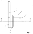
- Fig. 1 shows a side view of the rotary damper 2 with a damper housing 4, which is fastened via a fastening part (not shown) to a mass, ie the suspension or the vehicle body.
- An articulated lever 6 is mounted pivotably relative to the damper housing 4 and connected to a second mass, ie the vehicle body or the suspension.
- the articulation lever 6 is connected to a housing cover 8, which is rotatably mounted on the damper housing 4. Between the damper housing 4 and the housing cover 8, a voltage wave transmission 10 is arranged.
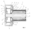
- Fig. 2 shows a section through the rotary damper along the line II-II of Fig.1 ,
- the rotary damper 2 includes the stress wave gear having a rigid internal unit having a rigid unit 12 which is connected to the damper housing 4, and having an external toothing flexible unit 14 which is connected to the housing cover 8, as will be described.
- the two units 12, 14 of the stress wave transmission are positively coupled via gears with each other for transmitting and / or converting a rotational movement between the lever 6 and the damper housing 4.
- a wave generator 16 is rotatably mounted relative to the damper housing 4, wherein at initiation a rotational force in the stress wave transmission with the rotation of the shaft generator 16, a deformation of the flexible unit 14 takes place.
- a rolling bearing 18 is arranged between the flexible unit and the wave generator 16.
- the flexible unit 14 has a toothed portion 20 located between the rigid unit 12 and the flexible unit 14. At the toothed portion 20, an axial wall portion 22 connects, to which a radial wall portion 24 connects, which is connected to the housing cover 4 via fasteners 26, 28, for example, rivets.
- a wrap spring 30 is looped around the axial wall portion 22 of the flexible unit 14.
- the wrap spring 30 is on the one hand on the housing cover 8 with the lever 6 and on the other hand on the rigid Unit 12 and the damper housing 4 connected to the mounting part (not shown).
- the wrap spring 30 is anchored on the damper housing 4 on the one hand via a first stop 32 on the rigid unit 12 and on the other hand via a second stop 34.
- the wrap spring 30 is designed in this embodiment of the rotary damper 2 so that the voltage wave transmission 10 is locked at a predetermined pivoting of the articulation lever 6 relative to the damper housing 4 by deformation of the flexible unit 14.
- the housing cover 8 is mounted on the rigid unit 12 and the damper housing 4 via a first roller bearing 36.
- a second roller bearing 38 is arranged between the housing cover 8 and a bearing part 40, which in turn is connected to the damper housing 4 and the mass connected to the damper housing 4.
- Fig. 2 Also shown is an electromagnetic damper motor having a rotor 42 with a magnet assembly 44 which is rotatably mounted on the bearing member 40 via two roller bearings 46, 48.
- the damper motor further includes a stator 50 which is connected to the damper housing 4 and has a coil arrangement to complete the damper motor.
- a pivoting of the articulation lever 6 relative to the damper housing 4 is a rotational movement of the Housing cover 8 via the radial wall portion 24, the axial wall portion 22 and the flexible unit 14 is introduced into the tension shaft gear 10, which rotates with a pivoting of the rotor 42 relative to the stator 44 according to the translation of the stress wave transmission 10.
- the damping force is opposed to such a pivoting.
- Fig. 3 shows a detailed perspective view of the damper housing 4 with the wrap spring 30. From the flexible unit 14 of the radial wall portion 24 and the axial wall portion 22 can be seen and the rigid unit 14 shown with the first stop 32 for the wrap spring 30.
Landscapes
- Engineering & Computer Science (AREA)
- General Engineering & Computer Science (AREA)
- Mechanical Engineering (AREA)
- Physics & Mathematics (AREA)
- Acoustics & Sound (AREA)
- Aviation & Aerospace Engineering (AREA)
- Electromagnetism (AREA)
- Retarders (AREA)
- Vibration Prevention Devices (AREA)
- Connection Of Motors, Electrical Generators, Mechanical Devices, And The Like (AREA)
Claims (7)
- Amortisseur de rotation (2) comprenant un boîtier d'amortisseur (4), qui entoure un moteur d'amortisseur électromagnétique et est fixé via une pièce de fixation à une première masse et un levier d'articulation (6) qui est monté à pivotement vis-à-vis du boîtier d'amortisseur (4) et est relié à une seconde masse, ainsi qu'une transmission harmonique (10) pour amortir les oscillations, qui présente une unité rigide (12) comportant une denture interne qui est reliée au boîtier d'amortisseur (4) et une unité souple (14) comportant une denture externe qui est reliée à la pièce de fixation, dans lequel les deux unités de la transmission harmonique (10) sont couplées l'une à l'autre mécaniquement via les dentures pour transmettre et/ou transformer un mouvement de rotation, et un générateur d'ondes monté à rotation dans l'unité souple (14), au cours de laquelle rotation l'unité souple est déformée,
caractérisé par
un ressort enroulé (30) agencé en coopération avec l'unité souple (14), qui est relié solidaire en rotation, d'une part, au levier d'articulation (6) et, d'autre part, à la pièce de fixation, dans lequel le ressort enroulé (30) est conçu pour bloquer la transmission harmonique (10) lors d'un pivotement préétabli du levier d'articulation (6) par rapport à la pièce de fixation par déformation de l'unité souple (14). - Amortisseur de rotation (2) selon la revendication 1, caractérisé en ce que le ressort enroulé (30) est fixé, d'une part, via une première butée (32) à l'unité rigide (12) et, d'autre part, via une seconde butée (34) à un couvercle de boîtier (8) monté à rotation sur le boîtier d'amortisseur (4) et relié au levier d'articulation (6).
- Amortisseur de rotation (2) selon la revendication 1, caractérisé en ce que l'unité souple (14) présente une section de denture (20) qui se situe entre l'unité rigide (12) et le générateur d'ondes (16) et une section de paroi (22) s'étendant axialement jusqu'à la transmission harmonique (10) et le ressort enroulé (26) est agencé autour de la section de paroi axiale (22).
- Amortisseur de rotation (2) selon la revendication 4, caractérisé en ce que la section de paroi axiale (22) présente à son extrémité éloignée de la section de denture (20) une section de paroi radiale (24) qui est reliée au couvercle de boîtier (8).
- Amortisseur de rotation (2) selon la revendication 1, caractérisé en ce que le moteur d'amortisseur électromagnétique comprend un rotor (42) et un stator (50) ainsi que des moyens pour produire un champ magnétique sur le rotor (42) et le stator (50), dans lequel le stator (50) est relié au boîtier d'amortisseur (4) et le rotor (42) est monté à rotation sur une partie de palier (40) agencée fixe sur le boîtier d'amortisseur (4).
- Amortisseur de rotation (2) selon la revendication 1, caractérisé en ce que le stator (50) est relié à l'unité rigide (12) et le rotor (42) au générateur d'ondes (16).
- Amortisseur de rotation (2) selon la revendication 1, caractérisé en ce que le stator (50) présente un agencement d'enroulements parcouru par un courant et le rotor (42) un agencement d'aimants (44).
Applications Claiming Priority (2)
| Application Number | Priority Date | Filing Date | Title |
|---|---|---|---|
| DE102014003219.1A DE102014003219A1 (de) | 2014-03-05 | 2014-03-05 | Elektromechanischer Rotationsdämpfer mit Zug- und Druckanschlag |
| PCT/EP2015/000223 WO2015131972A1 (fr) | 2014-03-05 | 2015-02-05 | Amortisseur de rotation électromécanique à butée de traction et de pression |
Publications (2)
| Publication Number | Publication Date |
|---|---|
| EP3114366A1 EP3114366A1 (fr) | 2017-01-11 |
| EP3114366B1 true EP3114366B1 (fr) | 2018-01-10 |
Family
ID=52450048
Family Applications (1)
| Application Number | Title | Priority Date | Filing Date |
|---|---|---|---|
| EP15702636.0A Not-in-force EP3114366B1 (fr) | 2014-03-05 | 2015-02-05 | Amortisseur de rotation électromécanique à butée de traction et de pression |
Country Status (5)
| Country | Link |
|---|---|
| US (1) | US9956840B2 (fr) |
| EP (1) | EP3114366B1 (fr) |
| CN (1) | CN106062413B (fr) |
| DE (1) | DE102014003219A1 (fr) |
| WO (1) | WO2015131972A1 (fr) |
Families Citing this family (6)
| Publication number | Priority date | Publication date | Assignee | Title |
|---|---|---|---|---|
| DE102016221307A1 (de) | 2016-10-28 | 2018-05-03 | Schaeffler Technologies AG & Co. KG | Aktuator |
| DE102016221306A1 (de) | 2016-10-28 | 2018-05-03 | Schaeffler Technologies AG & Co. KG | Verstellbare Radaufhängung |
| CN107878592B (zh) * | 2017-12-14 | 2023-05-02 | 中国科学院合肥物质科学研究院 | 一种用于四足机器人的独立悬架机构 |
| DE102018128028B3 (de) * | 2018-11-09 | 2020-03-05 | Schaeffler Technologies AG & Co. KG | Wellgetriebe für einen elektromechanischen Nockenwellenversteller |
| CN111623103B (zh) | 2019-06-07 | 2021-10-01 | 北京京西重工有限公司 | 应变波齿轮装置和包括应变波齿轮装置的车辆升降系统 |
| US12000470B2 (en) | 2019-06-07 | 2024-06-04 | Beijingwest Industries Co., Ltd | Compact belted strain wave gear apparatus and a vehicle lifting system including the compact belted strain wave gear apparatus |
Family Cites Families (30)
| Publication number | Priority date | Publication date | Assignee | Title |
|---|---|---|---|---|
| DE19747566C1 (de) | 1997-10-28 | 1999-04-08 | Fraunhofer Ges Forschung | Piezoangetriebenes Spannungswellen-Getriebe |
| DE10117934B4 (de) | 2001-04-10 | 2012-09-06 | Valeo Sicherheitssysteme Gmbh | Antrieb für Kraftfahrzeuge mit einer automatisch verschließbaren Fahrzeugtür |
| DE10137230C5 (de) | 2001-07-30 | 2005-11-17 | Falkenstein, Jens, Dipl.-Ing. | Elektrisch angetriebenes Spannungswellen-Getriebe |
| DE60226122T2 (de) | 2002-04-17 | 2009-05-14 | Ford Global Technologies, Inc., Dearborn | Aufhängungsanordnung |
| DE202005002501U1 (de) * | 2005-02-15 | 2005-04-21 | Reum Gmbh & Co. Betriebs Kg | Rotationsdämpfer |
| JP2007303592A (ja) * | 2006-05-12 | 2007-11-22 | Honda Motor Co Ltd | 波動歯車装置 |
| WO2008080231A1 (fr) * | 2007-01-05 | 2008-07-10 | Victhom Human Bionics Inc. | Mécanisme d'actionnement d'une articulation pour dispositif prothétique ou orthétique à transmission flexible |
| DE102009048818A1 (de) * | 2009-10-09 | 2011-04-14 | Audi Ag | Elektrischer Dämpfer |
| DE102010035088A1 (de) | 2010-08-21 | 2012-03-08 | Audi Ag | Radaufhängung für ein Kraftfahrzeug |
| DE102010035084A1 (de) | 2010-08-21 | 2012-02-23 | Audi Ag | Elektrischer Dämpfer für ein Kraftfahrzeug |
| DE102011009608A1 (de) | 2011-01-27 | 2012-08-02 | Audi Ag | Elektrischer Dämpfer |
| DE102011006094A1 (de) * | 2011-03-25 | 2012-09-27 | Zf Friedrichshafen Ag | Vorrichtung und Verfahren zum Dämpfen von Relativbewegungen zwischen zwei Massen |
| DE102011016540A1 (de) * | 2011-04-08 | 2012-10-11 | Audi Ag | Federungsanordnung für Radaufhängungen von Kraftfahrzeugen |
| DE102011101350A1 (de) | 2011-05-12 | 2012-11-15 | Audi Ag | Rotationsdämpfer |
| DE102011101701A1 (de) * | 2011-05-17 | 2012-11-22 | Audi Ag | Rotationsdämpfer |
| DE102011102743A1 (de) * | 2011-05-28 | 2012-11-29 | Audi Ag | Kraftfahrzeug |
| US9476494B2 (en) * | 2011-08-17 | 2016-10-25 | Harmonic Drive Systems Inc. | Flexible externally toothed gear for wave gear device |
| DE102011112130A1 (de) | 2011-09-01 | 2013-03-07 | Audi Ag | Luftfedervorrichtung für ein Kraftfahrzeug |
| DE102011112405B4 (de) | 2011-09-03 | 2014-10-09 | Audi Ag | Dämpferlager zur Abstützung einer Fahrwerkskomponente an einer Kraftfahrzeugkarosserie |
| CA2907579C (fr) | 2012-03-21 | 2020-09-22 | B-Temia Inc. | Embrayage limiteur de couple pour dispositifs orthetiques et prothetiques |
| DE102012007120A1 (de) | 2012-04-05 | 2013-10-10 | Audi Ag | Elektrischer Dämpfer |
| DE102012009168A1 (de) | 2012-05-08 | 2013-11-14 | Audi Ag | Dämpfungseinrichtung mit einem Rotationsdämpfer |
| DE102012020436B4 (de) | 2012-10-18 | 2018-09-20 | Audi Ag | Elektrischer Dämpfer für ein Kraftfahrzeug |
| DE102012021018A1 (de) | 2012-10-26 | 2014-05-15 | Audi Ag | Generator mit elektrischem Getriebe |
| DE102013004012B3 (de) | 2013-03-08 | 2014-03-06 | Audi Ag | Elektromechanischer Dämpfer |
| DE102013004956B4 (de) | 2013-03-22 | 2016-07-28 | Audi Ag | Rotationsdämpfer |
| DE102014003222B4 (de) * | 2014-03-05 | 2017-09-07 | Audi Ag | Koaxiale Federanordnung |
| DE102014006291B3 (de) | 2014-04-26 | 2015-09-03 | Audi Ag | Rotationsdämpfer |
| DE102014007844A1 (de) * | 2014-05-23 | 2015-11-26 | Audi Ag | Rotationsdämpfer |
| DE102014007956A1 (de) * | 2014-05-26 | 2015-11-26 | Audi Ag | Rotationsdämpfer |
-
2014
- 2014-03-05 DE DE102014003219.1A patent/DE102014003219A1/de not_active Withdrawn
-
2015
- 2015-02-05 EP EP15702636.0A patent/EP3114366B1/fr not_active Not-in-force
- 2015-02-05 WO PCT/EP2015/000223 patent/WO2015131972A1/fr not_active Ceased
- 2015-02-05 US US15/123,503 patent/US9956840B2/en active Active
- 2015-02-05 CN CN201580011288.5A patent/CN106062413B/zh not_active Expired - Fee Related
Also Published As
| Publication number | Publication date |
|---|---|
| US9956840B2 (en) | 2018-05-01 |
| CN106062413B (zh) | 2017-10-13 |
| WO2015131972A1 (fr) | 2015-09-11 |
| CN106062413A (zh) | 2016-10-26 |
| US20170072758A1 (en) | 2017-03-16 |
| DE102014003219A1 (de) | 2015-09-10 |
| EP3114366A1 (fr) | 2017-01-11 |
Similar Documents
| Publication | Publication Date | Title |
|---|---|---|
| EP3114366B1 (fr) | Amortisseur de rotation électromécanique à butée de traction et de pression | |
| EP2668048B1 (fr) | Amortisseur électrique | |
| EP3149356B1 (fr) | Amortisseur de rotation | |
| DE102010006392B3 (de) | Spannungswellengetriebe und Nockenwellenversteller mit Spannungswellengetriebe | |
| EP2775165B1 (fr) | Amortisseur électromécanique | |
| EP1863998B1 (fr) | Unité d'entraînement d'engrenage dotée d'un dispositif de blocage de couple de charge | |
| EP3997363B1 (fr) | Entraînement de commande comprenant un dispositif de limitation de couple | |
| EP2949491B1 (fr) | Amortisseur rotatif | |
| WO2004033834A1 (fr) | Dispositif d'engrenage conçu en particulier pour des mecanismes de reglage de vehicules automobiles | |
| EP2735088B1 (fr) | Dispositif d'entraînement de transmission | |
| EP1488121A1 (fr) | Dispositif de couplage d'un ensemble carter d'un equipement de couplage avec un ensemble rotor d'une machine electrique | |
| EP1719237A1 (fr) | Unite d'entrainement a transmission | |
| WO2017041793A1 (fr) | Déphaseur d'arbre à cames présentant un ressort | |
| DE102012212140B4 (de) | Bremsvorrichtung für eine direkt elektromechanisch aktuierte Planetengetriebeanordnung eines Sitzverstellmechanismus und Verfahren zum Betrieb einer Bremsvorrichtung | |
| EP2529125A1 (fr) | Système de paliers pour une unité d'entraînement et mécanisme de réglage muni d'un système de paliers | |
| WO2018177475A1 (fr) | Roue dentée multiple et ensemble formant engrenage comprenant la roue dentée multiple | |
| EP3146231B1 (fr) | Amortisseur de rotation | |
| DE10221625A1 (de) | Vorrichtung zur Kopplung einer Gehäuseanordnung einer Kopplungseinrichtung mit einer Rotoranordnung einer Elektromaschine | |
| DE102016207927B4 (de) | Stellantrieb | |
| DE102024138319B3 (de) | Antrieb, insbesondere Spindelantrieb | |
| DE102010035572A1 (de) | Getriebemotor | |
| DE102021211648B4 (de) | Welle-Nabe-Verbindung | |
| DE202024002509U1 (de) | Antrieb, insbesondere Spindelantrieb | |
| DE102012104119B4 (de) | Aktuator, insbesondere für ein Kraftfahrzeug | |
| DE102017105736B4 (de) | Verstellvorrichtung für einen Verbrennungsmotor |
Legal Events
| Date | Code | Title | Description |
|---|---|---|---|
| PUAI | Public reference made under article 153(3) epc to a published international application that has entered the european phase |
Free format text: ORIGINAL CODE: 0009012 |
|
| 17P | Request for examination filed |
Effective date: 20161005 |
|
| AK | Designated contracting states |
Kind code of ref document: A1 Designated state(s): AL AT BE BG CH CY CZ DE DK EE ES FI FR GB GR HR HU IE IS IT LI LT LU LV MC MK MT NL NO PL PT RO RS SE SI SK SM TR |
|
| AX | Request for extension of the european patent |
Extension state: BA ME |
|
| DAX | Request for extension of the european patent (deleted) | ||
| REG | Reference to a national code |
Ref country code: DE Ref legal event code: R079 Ref document number: 502015002838 Country of ref document: DE Free format text: PREVIOUS MAIN CLASS: F16F0015030000 Ipc: B60G0015020000 |
|
| GRAP | Despatch of communication of intention to grant a patent |
Free format text: ORIGINAL CODE: EPIDOSNIGR1 |
|
| RIC1 | Information provided on ipc code assigned before grant |
Ipc: F16F 15/02 20060101ALI20170926BHEP Ipc: B60G 15/02 20060101AFI20170926BHEP Ipc: B60G 13/14 20060101ALI20170926BHEP Ipc: F16F 15/03 20060101ALI20170926BHEP |
|
| INTG | Intention to grant announced |
Effective date: 20171030 |
|
| GRAS | Grant fee paid |
Free format text: ORIGINAL CODE: EPIDOSNIGR3 |
|
| GRAA | (expected) grant |
Free format text: ORIGINAL CODE: 0009210 |
|
| AK | Designated contracting states |
Kind code of ref document: B1 Designated state(s): AL AT BE BG CH CY CZ DE DK EE ES FI FR GB GR HR HU IE IS IT LI LT LU LV MC MK MT NL NO PL PT RO RS SE SI SK SM TR |
|
| REG | Reference to a national code |
Ref country code: CH Ref legal event code: EP Ref country code: AT Ref legal event code: REF Ref document number: 961975 Country of ref document: AT Kind code of ref document: T Effective date: 20180115 |
|
| REG | Reference to a national code |
Ref country code: IE Ref legal event code: FG4D Free format text: LANGUAGE OF EP DOCUMENT: GERMAN |
|
| REG | Reference to a national code |
Ref country code: DE Ref legal event code: R096 Ref document number: 502015002838 Country of ref document: DE |
|
| REG | Reference to a national code |
Ref country code: FR Ref legal event code: PLFP Year of fee payment: 4 |
|
| REG | Reference to a national code |
Ref country code: NL Ref legal event code: MP Effective date: 20180110 |
|
| PG25 | Lapsed in a contracting state [announced via postgrant information from national office to epo] |
Ref country code: NL Free format text: LAPSE BECAUSE OF FAILURE TO SUBMIT A TRANSLATION OF THE DESCRIPTION OR TO PAY THE FEE WITHIN THE PRESCRIBED TIME-LIMIT Effective date: 20180110 |
|
| PG25 | Lapsed in a contracting state [announced via postgrant information from national office to epo] |
Ref country code: CY Free format text: LAPSE BECAUSE OF FAILURE TO SUBMIT A TRANSLATION OF THE DESCRIPTION OR TO PAY THE FEE WITHIN THE PRESCRIBED TIME-LIMIT Effective date: 20180110 Ref country code: HR Free format text: LAPSE BECAUSE OF FAILURE TO SUBMIT A TRANSLATION OF THE DESCRIPTION OR TO PAY THE FEE WITHIN THE PRESCRIBED TIME-LIMIT Effective date: 20180110 Ref country code: NO Free format text: LAPSE BECAUSE OF FAILURE TO SUBMIT A TRANSLATION OF THE DESCRIPTION OR TO PAY THE FEE WITHIN THE PRESCRIBED TIME-LIMIT Effective date: 20180410 Ref country code: FI Free format text: LAPSE BECAUSE OF FAILURE TO SUBMIT A TRANSLATION OF THE DESCRIPTION OR TO PAY THE FEE WITHIN THE PRESCRIBED TIME-LIMIT Effective date: 20180110 Ref country code: ES Free format text: LAPSE BECAUSE OF FAILURE TO SUBMIT A TRANSLATION OF THE DESCRIPTION OR TO PAY THE FEE WITHIN THE PRESCRIBED TIME-LIMIT Effective date: 20180110 Ref country code: LT Free format text: LAPSE BECAUSE OF FAILURE TO SUBMIT A TRANSLATION OF THE DESCRIPTION OR TO PAY THE FEE WITHIN THE PRESCRIBED TIME-LIMIT Effective date: 20180110 |
|
| PG25 | Lapsed in a contracting state [announced via postgrant information from national office to epo] |
Ref country code: SE Free format text: LAPSE BECAUSE OF FAILURE TO SUBMIT A TRANSLATION OF THE DESCRIPTION OR TO PAY THE FEE WITHIN THE PRESCRIBED TIME-LIMIT Effective date: 20180110 Ref country code: LV Free format text: LAPSE BECAUSE OF FAILURE TO SUBMIT A TRANSLATION OF THE DESCRIPTION OR TO PAY THE FEE WITHIN THE PRESCRIBED TIME-LIMIT Effective date: 20180110 Ref country code: PL Free format text: LAPSE BECAUSE OF FAILURE TO SUBMIT A TRANSLATION OF THE DESCRIPTION OR TO PAY THE FEE WITHIN THE PRESCRIBED TIME-LIMIT Effective date: 20180110 Ref country code: RS Free format text: LAPSE BECAUSE OF FAILURE TO SUBMIT A TRANSLATION OF THE DESCRIPTION OR TO PAY THE FEE WITHIN THE PRESCRIBED TIME-LIMIT Effective date: 20180110 Ref country code: IS Free format text: LAPSE BECAUSE OF FAILURE TO SUBMIT A TRANSLATION OF THE DESCRIPTION OR TO PAY THE FEE WITHIN THE PRESCRIBED TIME-LIMIT Effective date: 20180510 Ref country code: BG Free format text: LAPSE BECAUSE OF FAILURE TO SUBMIT A TRANSLATION OF THE DESCRIPTION OR TO PAY THE FEE WITHIN THE PRESCRIBED TIME-LIMIT Effective date: 20180410 Ref country code: GR Free format text: LAPSE BECAUSE OF FAILURE TO SUBMIT A TRANSLATION OF THE DESCRIPTION OR TO PAY THE FEE WITHIN THE PRESCRIBED TIME-LIMIT Effective date: 20180411 |
|
| REG | Reference to a national code |
Ref country code: CH Ref legal event code: PL |
|
| PG25 | Lapsed in a contracting state [announced via postgrant information from national office to epo] |
Ref country code: MT Free format text: LAPSE BECAUSE OF FAILURE TO SUBMIT A TRANSLATION OF THE DESCRIPTION OR TO PAY THE FEE WITHIN THE PRESCRIBED TIME-LIMIT Effective date: 20180110 |
|
| REG | Reference to a national code |
Ref country code: DE Ref legal event code: R097 Ref document number: 502015002838 Country of ref document: DE |
|
| PG25 | Lapsed in a contracting state [announced via postgrant information from national office to epo] |
Ref country code: AL Free format text: LAPSE BECAUSE OF FAILURE TO SUBMIT A TRANSLATION OF THE DESCRIPTION OR TO PAY THE FEE WITHIN THE PRESCRIBED TIME-LIMIT Effective date: 20180110 Ref country code: MC Free format text: LAPSE BECAUSE OF FAILURE TO SUBMIT A TRANSLATION OF THE DESCRIPTION OR TO PAY THE FEE WITHIN THE PRESCRIBED TIME-LIMIT Effective date: 20180110 Ref country code: IT Free format text: LAPSE BECAUSE OF FAILURE TO SUBMIT A TRANSLATION OF THE DESCRIPTION OR TO PAY THE FEE WITHIN THE PRESCRIBED TIME-LIMIT Effective date: 20180110 Ref country code: RO Free format text: LAPSE BECAUSE OF FAILURE TO SUBMIT A TRANSLATION OF THE DESCRIPTION OR TO PAY THE FEE WITHIN THE PRESCRIBED TIME-LIMIT Effective date: 20180110 Ref country code: EE Free format text: LAPSE BECAUSE OF FAILURE TO SUBMIT A TRANSLATION OF THE DESCRIPTION OR TO PAY THE FEE WITHIN THE PRESCRIBED TIME-LIMIT Effective date: 20180110 |
|
| PLBE | No opposition filed within time limit |
Free format text: ORIGINAL CODE: 0009261 |
|
| STAA | Information on the status of an ep patent application or granted ep patent |
Free format text: STATUS: NO OPPOSITION FILED WITHIN TIME LIMIT |
|
| REG | Reference to a national code |
Ref country code: IE Ref legal event code: MM4A |
|
| REG | Reference to a national code |
Ref country code: BE Ref legal event code: MM Effective date: 20180228 |
|
| PG25 | Lapsed in a contracting state [announced via postgrant information from national office to epo] |
Ref country code: LI Free format text: LAPSE BECAUSE OF NON-PAYMENT OF DUE FEES Effective date: 20180228 Ref country code: LU Free format text: LAPSE BECAUSE OF NON-PAYMENT OF DUE FEES Effective date: 20180205 Ref country code: SK Free format text: LAPSE BECAUSE OF FAILURE TO SUBMIT A TRANSLATION OF THE DESCRIPTION OR TO PAY THE FEE WITHIN THE PRESCRIBED TIME-LIMIT Effective date: 20180110 Ref country code: CZ Free format text: LAPSE BECAUSE OF FAILURE TO SUBMIT A TRANSLATION OF THE DESCRIPTION OR TO PAY THE FEE WITHIN THE PRESCRIBED TIME-LIMIT Effective date: 20180110 Ref country code: CH Free format text: LAPSE BECAUSE OF NON-PAYMENT OF DUE FEES Effective date: 20180228 Ref country code: DK Free format text: LAPSE BECAUSE OF FAILURE TO SUBMIT A TRANSLATION OF THE DESCRIPTION OR TO PAY THE FEE WITHIN THE PRESCRIBED TIME-LIMIT Effective date: 20180110 Ref country code: SM Free format text: LAPSE BECAUSE OF FAILURE TO SUBMIT A TRANSLATION OF THE DESCRIPTION OR TO PAY THE FEE WITHIN THE PRESCRIBED TIME-LIMIT Effective date: 20180110 |
|
| 26N | No opposition filed |
Effective date: 20181011 |
|
| PG25 | Lapsed in a contracting state [announced via postgrant information from national office to epo] |
Ref country code: IE Free format text: LAPSE BECAUSE OF NON-PAYMENT OF DUE FEES Effective date: 20180205 |
|
| PG25 | Lapsed in a contracting state [announced via postgrant information from national office to epo] |
Ref country code: SI Free format text: LAPSE BECAUSE OF FAILURE TO SUBMIT A TRANSLATION OF THE DESCRIPTION OR TO PAY THE FEE WITHIN THE PRESCRIBED TIME-LIMIT Effective date: 20180110 Ref country code: BE Free format text: LAPSE BECAUSE OF NON-PAYMENT OF DUE FEES Effective date: 20180228 |
|
| PG25 | Lapsed in a contracting state [announced via postgrant information from national office to epo] |
Ref country code: TR Free format text: LAPSE BECAUSE OF FAILURE TO SUBMIT A TRANSLATION OF THE DESCRIPTION OR TO PAY THE FEE WITHIN THE PRESCRIBED TIME-LIMIT Effective date: 20180110 |
|
| PG25 | Lapsed in a contracting state [announced via postgrant information from national office to epo] |
Ref country code: PT Free format text: LAPSE BECAUSE OF FAILURE TO SUBMIT A TRANSLATION OF THE DESCRIPTION OR TO PAY THE FEE WITHIN THE PRESCRIBED TIME-LIMIT Effective date: 20180110 |
|
| PG25 | Lapsed in a contracting state [announced via postgrant information from national office to epo] |
Ref country code: HU Free format text: LAPSE BECAUSE OF FAILURE TO SUBMIT A TRANSLATION OF THE DESCRIPTION OR TO PAY THE FEE WITHIN THE PRESCRIBED TIME-LIMIT; INVALID AB INITIO Effective date: 20150205 Ref country code: MK Free format text: LAPSE BECAUSE OF NON-PAYMENT OF DUE FEES Effective date: 20180110 |
|
| REG | Reference to a national code |
Ref country code: AT Ref legal event code: MM01 Ref document number: 961975 Country of ref document: AT Kind code of ref document: T Effective date: 20200205 |
|
| PG25 | Lapsed in a contracting state [announced via postgrant information from national office to epo] |
Ref country code: AT Free format text: LAPSE BECAUSE OF NON-PAYMENT OF DUE FEES Effective date: 20200205 |
|
| PGFP | Annual fee paid to national office [announced via postgrant information from national office to epo] |
Ref country code: FR Payment date: 20230222 Year of fee payment: 9 |
|
| PGFP | Annual fee paid to national office [announced via postgrant information from national office to epo] |
Ref country code: GB Payment date: 20230220 Year of fee payment: 9 Ref country code: DE Payment date: 20230228 Year of fee payment: 9 |
|
| P01 | Opt-out of the competence of the unified patent court (upc) registered |
Effective date: 20230530 |
|
| REG | Reference to a national code |
Ref country code: DE Ref legal event code: R119 Ref document number: 502015002838 Country of ref document: DE |
|
| GBPC | Gb: european patent ceased through non-payment of renewal fee |
Effective date: 20240205 |
|
| PG25 | Lapsed in a contracting state [announced via postgrant information from national office to epo] |
Ref country code: DE Free format text: LAPSE BECAUSE OF NON-PAYMENT OF DUE FEES Effective date: 20240903 |
|
| PG25 | Lapsed in a contracting state [announced via postgrant information from national office to epo] |
Ref country code: GB Free format text: LAPSE BECAUSE OF NON-PAYMENT OF DUE FEES Effective date: 20240205 |
|
| PG25 | Lapsed in a contracting state [announced via postgrant information from national office to epo] |
Ref country code: FR Free format text: LAPSE BECAUSE OF NON-PAYMENT OF DUE FEES Effective date: 20240229 |
|
| PG25 | Lapsed in a contracting state [announced via postgrant information from national office to epo] |
Ref country code: GB Free format text: LAPSE BECAUSE OF NON-PAYMENT OF DUE FEES Effective date: 20240205 Ref country code: FR Free format text: LAPSE BECAUSE OF NON-PAYMENT OF DUE FEES Effective date: 20240229 Ref country code: DE Free format text: LAPSE BECAUSE OF NON-PAYMENT OF DUE FEES Effective date: 20240903 |