EP3114367B1 - Amortisseur pour système hydraulique - Google Patents
Amortisseur pour système hydraulique Download PDFInfo
- Publication number
- EP3114367B1 EP3114367B1 EP15758760.1A EP15758760A EP3114367B1 EP 3114367 B1 EP3114367 B1 EP 3114367B1 EP 15758760 A EP15758760 A EP 15758760A EP 3114367 B1 EP3114367 B1 EP 3114367B1
- Authority
- EP
- European Patent Office
- Prior art keywords
- plate
- stopper
- flow
- use according
- shock absorber
- Prior art date
- Legal status (The legal status is an assumption and is not a legal conclusion. Google has not performed a legal analysis and makes no representation as to the accuracy of the status listed.)
- Active
Links
Images
Classifications
-
- F—MECHANICAL ENGINEERING; LIGHTING; HEATING; WEAPONS; BLASTING
- F16—ENGINEERING ELEMENTS AND UNITS; GENERAL MEASURES FOR PRODUCING AND MAINTAINING EFFECTIVE FUNCTIONING OF MACHINES OR INSTALLATIONS; THERMAL INSULATION IN GENERAL
- F16F—SPRINGS; SHOCK-ABSORBERS; MEANS FOR DAMPING VIBRATION
- F16F15/00—Suppression of vibrations in systems; Means or arrangements for avoiding or reducing out-of-balance forces, e.g. due to motion
-
- F—MECHANICAL ENGINEERING; LIGHTING; HEATING; WEAPONS; BLASTING
- F16—ENGINEERING ELEMENTS AND UNITS; GENERAL MEASURES FOR PRODUCING AND MAINTAINING EFFECTIVE FUNCTIONING OF MACHINES OR INSTALLATIONS; THERMAL INSULATION IN GENERAL
- F16L—PIPES; JOINTS OR FITTINGS FOR PIPES; SUPPORTS FOR PIPES, CABLES OR PROTECTIVE TUBING; MEANS FOR THERMAL INSULATION IN GENERAL
- F16L55/00—Devices or appurtenances for use in, or in connection with, pipes or pipe systems
- F16L55/02—Energy absorbers; Noise absorbers
- F16L55/027—Throttle passages
- F16L55/02763—Throttle passages using an element with multiple tubes
-
- F—MECHANICAL ENGINEERING; LIGHTING; HEATING; WEAPONS; BLASTING
- F16—ENGINEERING ELEMENTS AND UNITS; GENERAL MEASURES FOR PRODUCING AND MAINTAINING EFFECTIVE FUNCTIONING OF MACHINES OR INSTALLATIONS; THERMAL INSULATION IN GENERAL
- F16F—SPRINGS; SHOCK-ABSORBERS; MEANS FOR DAMPING VIBRATION
- F16F9/00—Springs, vibration-dampers, shock-absorbers, or similarly-constructed movement-dampers using a fluid or the equivalent as damping medium
- F16F9/32—Details
- F16F9/34—Special valve constructions; Shape or construction of throttling passages
- F16F9/348—Throttling passages in the form of annular discs or other plate-like elements which may or may not have a spring action, operating in opposite directions or singly, e.g. annular discs positioned on top of the valve or piston body
-
- F—MECHANICAL ENGINEERING; LIGHTING; HEATING; WEAPONS; BLASTING
- F16—ENGINEERING ELEMENTS AND UNITS; GENERAL MEASURES FOR PRODUCING AND MAINTAINING EFFECTIVE FUNCTIONING OF MACHINES OR INSTALLATIONS; THERMAL INSULATION IN GENERAL
- F16K—VALVES; TAPS; COCKS; ACTUATING-FLOATS; DEVICES FOR VENTING OR AERATING
- F16K47/00—Means in valves for absorbing fluid energy
- F16K47/08—Means in valves for absorbing fluid energy for decreasing pressure or noise level and having a throttling member separate from the closure member, e.g. screens, slots, labyrinths
-
- F—MECHANICAL ENGINEERING; LIGHTING; HEATING; WEAPONS; BLASTING
- F16—ENGINEERING ELEMENTS AND UNITS; GENERAL MEASURES FOR PRODUCING AND MAINTAINING EFFECTIVE FUNCTIONING OF MACHINES OR INSTALLATIONS; THERMAL INSULATION IN GENERAL
- F16L—PIPES; JOINTS OR FITTINGS FOR PIPES; SUPPORTS FOR PIPES, CABLES OR PROTECTIVE TUBING; MEANS FOR THERMAL INSULATION IN GENERAL
- F16L55/00—Devices or appurtenances for use in, or in connection with, pipes or pipe systems
- F16L55/02—Energy absorbers; Noise absorbers
- F16L55/033—Noise absorbers
- F16L55/0333—Noise absorbers by means of an active system
-
- F—MECHANICAL ENGINEERING; LIGHTING; HEATING; WEAPONS; BLASTING
- F15—FLUID-PRESSURE ACTUATORS; HYDRAULICS OR PNEUMATICS IN GENERAL
- F15B—SYSTEMS ACTING BY MEANS OF FLUIDS IN GENERAL; FLUID-PRESSURE ACTUATORS, e.g. SERVOMOTORS; DETAILS OF FLUID-PRESSURE SYSTEMS, NOT OTHERWISE PROVIDED FOR
- F15B13/00—Details of servomotor systems ; Valves for servomotor systems
- F15B13/02—Fluid distribution or supply devices characterised by their adaptation to the control of servomotors
- F15B13/026—Pressure compensating valves
-
- F—MECHANICAL ENGINEERING; LIGHTING; HEATING; WEAPONS; BLASTING
- F15—FLUID-PRESSURE ACTUATORS; HYDRAULICS OR PNEUMATICS IN GENERAL
- F15B—SYSTEMS ACTING BY MEANS OF FLUIDS IN GENERAL; FLUID-PRESSURE ACTUATORS, e.g. SERVOMOTORS; DETAILS OF FLUID-PRESSURE SYSTEMS, NOT OTHERWISE PROVIDED FOR
- F15B2211/00—Circuits for servomotor systems
- F15B2211/50—Pressure control
- F15B2211/505—Pressure control characterised by the type of pressure control means
- F15B2211/50563—Pressure control characterised by the type of pressure control means the pressure control means controlling a differential pressure
- F15B2211/50572—Pressure control characterised by the type of pressure control means the pressure control means controlling a differential pressure using a pressure compensating valve for controlling the pressure difference across a flow control valve
-
- F—MECHANICAL ENGINEERING; LIGHTING; HEATING; WEAPONS; BLASTING
- F15—FLUID-PRESSURE ACTUATORS; HYDRAULICS OR PNEUMATICS IN GENERAL
- F15B—SYSTEMS ACTING BY MEANS OF FLUIDS IN GENERAL; FLUID-PRESSURE ACTUATORS, e.g. SERVOMOTORS; DETAILS OF FLUID-PRESSURE SYSTEMS, NOT OTHERWISE PROVIDED FOR
- F15B2211/00—Circuits for servomotor systems
- F15B2211/50—Pressure control
- F15B2211/575—Pilot pressure control
- F15B2211/5756—Pilot pressure control for opening a valve
-
- F—MECHANICAL ENGINEERING; LIGHTING; HEATING; WEAPONS; BLASTING
- F15—FLUID-PRESSURE ACTUATORS; HYDRAULICS OR PNEUMATICS IN GENERAL
- F15B—SYSTEMS ACTING BY MEANS OF FLUIDS IN GENERAL; FLUID-PRESSURE ACTUATORS, e.g. SERVOMOTORS; DETAILS OF FLUID-PRESSURE SYSTEMS, NOT OTHERWISE PROVIDED FOR
- F15B2211/00—Circuits for servomotor systems
- F15B2211/60—Circuit components or control therefor
- F15B2211/635—Circuits providing pilot pressure to pilot pressure-controlled fluid circuit elements
Definitions
- choke - check valve dampers are previously known as dampers of control flows and one must have two different pieces of them in parallel in line if one wants to have a different kind of damping in one direction than what the other direction has. Chokers that are located in these can also be adjustable but still they don't always react in a positive way to vibrations that occur in the fluid line that is directed to the control valve and their adjustments don't always stay in the set value and are not always accurate.
- Document JP 3 471 438 B2 discloses a valve structure for buffer.
- Document US 6 202 805 B1 discloses a shock absorber having bidirectional valve and flow restricting passage parallel to the valve.
- Document DE 196 42 837 C1 discloses a servo-assisted steering with a damping valve.
- Document DE 43 23 179 C1 discloses a hydraulically supported servo-assisted steering.
- Document US 5 996 748 A discloses a damping force adjusting type hydraulic shock absorber.
- the shock absorber is a stopper which restricts the run of the control flow to be damped which absorber is equipped with one or several ducts which let the flow go through the mentioned stopper when the other orifice of the mentioned duct is being blocked with a plate in such a way that the bending of the mentioned plate due to the pressure of the flow coming along the mentioned duct opens access for the flow through the mentioned stopper.
- the significant advantage of the absorber according to the invention is the fact that damping can be achieved for the hydraulic fluid which runs to the controlling valve in both flowing directions and as different volumes, if needed.
- the absorber can easily be adjusted regarding its properties according to the need of the speed and vibration control of the need for control of all kinds of valves separately in both directions.
- the absorber can be located in the stem of the valve to be controlled, it can be a separate part in the valve or be its independent component in a pipework that directs the control pressure.
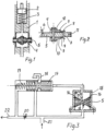
- the stem 2 of the control valve located inside the body 1 and the spring 3 are shown.
- the pressure line of the controlling hydraulic fluid runs through the damper arrangement 4, 5 according to the invention to the stem 2.
- the damper arrangement comprises a stopper 5 which stopper is assembled to prevent the control flow from running to the stem 2 or away from there.
- the stopper 5 comprises ducts 6 and 7 along which the pressure flow could run through the stopper if the ducts 6 and 7 were not closed with plates 8 - 10, in other words with shimming plates.
- the plates 8 that are against the stopper 5 have the largest outer diameter in such a way that when they are in an direct position, they cover the other orifices of the ducts 6 and 7.
- the other plates 9, 10 have a smaller outer diameter.
- the absorber is in a free state in which case pressure difference does not have an effect over the absorber.
- pressure difference for its part has an effect over the absorber to such an extent that at least the undermost plate 8 is bent and lets the hydraulic fluid flow through the stopper 5 along the duct 7.
- the diminishing of the pressure difference closes the duct 7 and then the plate 8 is restored back to its direct form.
- the stopper 5 is attached to the flange of the body 1, which can be divided, through bolt holes 11 that are located in the stopper in which case the absorber can be revealed and its plates 8-10 can be changed for example in order to change the adjustment properties. With the plates 9 and 10 the bending capacity of the undermost plate 8 can be affected.
- the plates 8 - 10 are stacked and tied so that they rest on the middle bolt 4.
- the middle bolt 4 can be opened at the other end for example with the help of a nut that can be unscrewed.
- the absorber damps the vibration occuring in the control flow most effectively in the state of the figure 2 in which case the plate 8 is in a sensitive state due to the pressure difference opening and closing the duct 7 when the pressure difference changes.
- a pressure compensated flow controller is shown schematically.
- the main flow comes in at the point 21 and comes out at the point 22.
- the position of the valve stem 17 and its movements adjust the amount of the flow being removed through an aggregate 18.
- the absorber 5, 12 - 14 is located at the body 15 with the help of retaining rings 16.
- the pressure controlling the stem 17 goes through the absorber and a sufficient pressure difference opens the duct through the stopper 5.
- the undermost plate 12 bends most at its inner edge due to the pressure and the flow then has an access to the stem 17 along the right hand duct.
- the body 15 is also divided with a flange joint in which case the absorber arrangement can be disassembled and re-assembled.
- the plates 12 - 14 are plate rings which have an equally sized outer diameter in which case only their inner diameter varies.
- the undermost plate 12 covers at least the orifice of the other duct.
- the absorber damps the movements of the stem 17 and prevents vibrations from occuring.
- the left hand duct that is located in the stopper 5 lets the flow run back from the stem 17 if the pressure difference over the absorber is sufficient.
- the plates 8-10 and 12 - 14 are most advantageously round spring steel rings the thickness of which rings is less than 20 % of the outer diameter.
- the shape of their outer edge can also deviate from the round form, for example it can be an angular shape, most advantageously then when they are tied with the help of the perch bolt 5 according to the figures 1 and 2 .
Landscapes
- Engineering & Computer Science (AREA)
- General Engineering & Computer Science (AREA)
- Mechanical Engineering (AREA)
- Physics & Mathematics (AREA)
- Acoustics & Sound (AREA)
- Aviation & Aerospace Engineering (AREA)
- Fluid-Damping Devices (AREA)
- Details Of Valves (AREA)
- Vibration Prevention Devices (AREA)
- Safety Valves (AREA)
Claims (7)
- Utilisation d'un amortisseur pour amortir un flux de commande qui doit être dirigé vers la soupape de commande appartenant à un système hydraulique, la soupape de commande comprenant une tige de soupape (17) et la pression commandant la tige de soupape (17) est configurée pour traverser l'amortisseur, caractérisée en ce que l'amortisseur est une butée (5) qui limite la course du flux de commande à amortir, lequel amortisseur est équipé avec un ou plusieurs conduits (6, 7) qui laisse le flux traverser la butée (5) mentionnée, lorsque l'autre orifice du conduit mentionné est bloqué avec une plaque (8), (12) de sorte que la flexion de la plaque mentionnée ouvre l'accès pour le flux de commande à travers la butée (5) mentionnée en raison de la pression du flux venant le long du conduit (6, 7) mentionné.
- Utilisation selon la revendication 1, caractérisée en ce que la plaque (8), (12) est une bague ronde, dont l'épaisseur de la bague est inférieure à 20% de son diamètre externe.
- Utilisation selon la revendication 1, caractérisé en ce que la pluralité de plaques rondes (8 - 10) sont empilées les unes sur les autres, auquel cas, la plaque (8) qui est positionnée contre la butée (5), a le plus grand diamètre externe.
- Utilisation selon la revendication 1, caractérisée en ce que la pluralité de plaques (12 - 14) sont empilées les unes sur les autres, auquel cas, la plaque (12) qui est positionnée contre la butée (5), a le plus petit diamètre interne.
- Utilisation selon la revendication 1, caractérisée en ce que la flexion du bord externe de la plaque (8) ouvre la trajectoire de flux pour le fluide hydraulique.
- Utilisation selon la revendication 1, caractérisée en ce que la flexion du bord interne de la plaque (12) ouvre la trajectoire de flux pour le fluide hydraulique.
- Utilisation selon la revendication 1, caractérisée en ce que la forme du bord externe de la plaque (8 - 10), (12 - 14) dévie de la forme ronde.
Applications Claiming Priority (2)
| Application Number | Priority Date | Filing Date | Title |
|---|---|---|---|
| FI20140062A FI125755B (fi) | 2014-03-05 | 2014-03-05 | Hydraulisessa järjestelmässä käytettävä vaimennin |
| PCT/FI2015/000008 WO2015132451A1 (fr) | 2014-03-05 | 2015-03-05 | Amortisseur pour système hydraulique |
Publications (4)
| Publication Number | Publication Date |
|---|---|
| EP3114367A1 EP3114367A1 (fr) | 2017-01-11 |
| EP3114367A4 EP3114367A4 (fr) | 2017-12-13 |
| EP3114367C0 EP3114367C0 (fr) | 2024-10-02 |
| EP3114367B1 true EP3114367B1 (fr) | 2024-10-02 |
Family
ID=54054621
Family Applications (1)
| Application Number | Title | Priority Date | Filing Date |
|---|---|---|---|
| EP15758760.1A Active EP3114367B1 (fr) | 2014-03-05 | 2015-03-05 | Amortisseur pour système hydraulique |
Country Status (5)
| Country | Link |
|---|---|
| US (1) | US10132438B2 (fr) |
| EP (1) | EP3114367B1 (fr) |
| CN (1) | CN106062414B (fr) |
| FI (1) | FI125755B (fr) |
| WO (1) | WO2015132451A1 (fr) |
Families Citing this family (2)
| Publication number | Priority date | Publication date | Assignee | Title |
|---|---|---|---|---|
| US10544878B2 (en) * | 2017-11-14 | 2020-01-28 | Forum Us, Inc. | Flow control assembly for subsea applications |
| CN111753378A (zh) * | 2020-04-30 | 2020-10-09 | 江苏高科石化股份有限公司 | 一种石化生产中质量阻尼器控制管道振动的多胞体滤波方法 |
Citations (3)
| Publication number | Priority date | Publication date | Assignee | Title |
|---|---|---|---|---|
| DE4323179C1 (de) * | 1993-07-10 | 1994-11-17 | Daimler Benz Ag | Hydraulisch unterstützte Servolenkung |
| DE19642837C1 (de) * | 1996-10-17 | 1998-01-29 | Daimler Benz Ag | Dämpferventil |
| US5996748A (en) * | 1996-03-19 | 1999-12-07 | Tokico Ltd. | Damping force adjusting type hydraulic shock absorber |
Family Cites Families (22)
| Publication number | Priority date | Publication date | Assignee | Title |
|---|---|---|---|---|
| GB1004233A (en) * | 1962-12-13 | 1965-09-15 | Daimler Benz Ag | Improvements in adjustable hydraulic shock absorbers |
| FR1553977A (fr) * | 1967-12-08 | 1969-01-17 | ||
| US3621951A (en) * | 1968-12-30 | 1971-11-23 | Leopold Franz Schmid | Throttle valve |
| DE2340987A1 (de) * | 1973-08-14 | 1975-02-27 | Bilstein August Fa | Stossdaempferventil, insbesondere damit ausgeruesteter kolben fuer hydropneumatische kraftfahrzeug-einrohrdaempfer |
| US4024889A (en) * | 1974-05-14 | 1977-05-24 | Smith Paul D | Dynamic control valve for modifying fluid flow |
| US3957140A (en) * | 1975-02-11 | 1976-05-18 | Carl Ullrich Peddinghaus | Shock-absorber piston |
| US4098296A (en) * | 1976-12-27 | 1978-07-04 | United Technologies Corporation | Variable area reed flow restrictor |
| US4262844A (en) * | 1980-01-22 | 1981-04-21 | Mark Controls Corporation | Control valve |
| DE3503152A1 (de) * | 1985-01-31 | 1986-08-14 | Daimler-Benz Ag, 7000 Stuttgart | Schwingungsdaempfer fuer fahrzeuge |
| US4934491A (en) | 1987-12-14 | 1990-06-19 | Atsugi Motor Parts Company, Limited | Shock absorber with improved structure of thrusting piston assembly |
| JP2694465B2 (ja) * | 1989-05-19 | 1997-12-24 | トキコ株式会社 | 油圧緩衝器 |
| US4972929A (en) * | 1989-06-07 | 1990-11-27 | Lord Corporation | Bidirectional dual disc valve assembly |
| DE4308297A1 (fr) | 1992-03-20 | 1993-09-23 | Rexroth Mannesmann Gmbh | |
| DE4318553C2 (de) * | 1993-06-04 | 1995-05-18 | Daimler Benz Ag | Adaptiver hydropneumatischer Pulsationsdämpfer |
| JP3471438B2 (ja) | 1993-12-06 | 2003-12-02 | 株式会社ショーワ | 緩衝器のバルブ構造 |
| US5425398A (en) * | 1994-03-28 | 1995-06-20 | General Motors Corporation | Valve for automotive damper |
| FR2772447A1 (fr) * | 1997-12-11 | 1999-06-18 | Toyota Motor Co Ltd | Amortisseur comportant une soupape bidirectionnelle et un passage de limitation d'ecoulement parallele a la soupape |
| JP2001041271A (ja) | 1999-07-28 | 2001-02-13 | Tokico Ltd | 油圧緩衝器 |
| US6655512B2 (en) * | 2000-12-19 | 2003-12-02 | Delphi Technologies, Inc. | Variable area low speed orifice in a vehicle damper |
| DE10206104C1 (de) * | 2002-02-13 | 2003-05-28 | Thyssen Krupp Bilstein Gmbh | Dämpferkolben für hydraulische Einrichtungen |
| CA2535174C (fr) * | 2003-08-12 | 2013-10-01 | Graeme K. Robertson | Dispositif d'amortisseur |
| JP2009063079A (ja) | 2007-09-06 | 2009-03-26 | Kayaba Ind Co Ltd | 緩衝器のバルブ構造 |
-
2014
- 2014-03-05 FI FI20140062A patent/FI125755B/fi active IP Right Grant
-
2015
- 2015-03-05 CN CN201580012045.3A patent/CN106062414B/zh active Active
- 2015-03-05 US US15/123,884 patent/US10132438B2/en active Active
- 2015-03-05 WO PCT/FI2015/000008 patent/WO2015132451A1/fr not_active Ceased
- 2015-03-05 EP EP15758760.1A patent/EP3114367B1/fr active Active
Patent Citations (3)
| Publication number | Priority date | Publication date | Assignee | Title |
|---|---|---|---|---|
| DE4323179C1 (de) * | 1993-07-10 | 1994-11-17 | Daimler Benz Ag | Hydraulisch unterstützte Servolenkung |
| US5996748A (en) * | 1996-03-19 | 1999-12-07 | Tokico Ltd. | Damping force adjusting type hydraulic shock absorber |
| DE19642837C1 (de) * | 1996-10-17 | 1998-01-29 | Daimler Benz Ag | Dämpferventil |
Also Published As
| Publication number | Publication date |
|---|---|
| US10132438B2 (en) | 2018-11-20 |
| FI125755B (fi) | 2016-02-15 |
| US20170016566A1 (en) | 2017-01-19 |
| CN106062414A (zh) | 2016-10-26 |
| EP3114367A4 (fr) | 2017-12-13 |
| EP3114367C0 (fr) | 2024-10-02 |
| FI20140062A7 (fi) | 2015-09-06 |
| WO2015132451A1 (fr) | 2015-09-11 |
| EP3114367A1 (fr) | 2017-01-11 |
| CN106062414B (zh) | 2019-02-22 |
Similar Documents
| Publication | Publication Date | Title |
|---|---|---|
| US10598247B2 (en) | Valve for hydraulic damper | |
| KR101825863B1 (ko) | 실린더 장치 | |
| US20070084687A1 (en) | Vibration damper with adjustable damping force | |
| EP2118515B1 (fr) | Elément amortisseur comportant des conduites hydrauliques | |
| CN107567552B (zh) | 可调节减振器 | |
| EP1983213A2 (fr) | Absorbeur de chocs à pression fluide réglable de force d'amortissement | |
| JP6417281B2 (ja) | 緩衝器 | |
| EP1659309B1 (fr) | Arrangement pour l'amortissement de vibrations | |
| CN102878236A (zh) | 具有紧急操作阀的可调节的阻尼阀装置 | |
| JP2018529051A5 (fr) | ||
| JP2015215046A (ja) | シリンダ装置 | |
| WO2014170304A1 (fr) | Agencement de vanne | |
| US20190323183A1 (en) | Multipurpose viscous damper | |
| MX2019013389A (es) | Amortiguador de impacto con bloqueo selectivo bidireccional, grupo de ruedas y motocicleta del mismo. | |
| US10132438B2 (en) | Shock absorber for hydraulic system | |
| JP2015113588A (ja) | 制振用オイルダンパー、および、建築物 | |
| JP6305102B2 (ja) | 流体圧緩衝器 | |
| US11739809B2 (en) | Throttle point with a valve body with a changing diameter | |
| EP4317738A1 (fr) | Amortisseur hydraulique | |
| JP6214227B2 (ja) | 油圧緩衝器 | |
| EP3411608B1 (fr) | Support hydraulique avec canal d'absorption oscillant commutable | |
| JP2017053402A (ja) | 調圧弁及びオイルダンパー | |
| JP6565442B2 (ja) | シリンダ装置 | |
| JP6770458B2 (ja) | 横置き型ダンパ | |
| JP2009243591A5 (fr) |
Legal Events
| Date | Code | Title | Description |
|---|---|---|---|
| STAA | Information on the status of an ep patent application or granted ep patent |
Free format text: STATUS: THE INTERNATIONAL PUBLICATION HAS BEEN MADE |
|
| PUAI | Public reference made under article 153(3) epc to a published international application that has entered the european phase |
Free format text: ORIGINAL CODE: 0009012 |
|
| STAA | Information on the status of an ep patent application or granted ep patent |
Free format text: STATUS: REQUEST FOR EXAMINATION WAS MADE |
|
| 17P | Request for examination filed |
Effective date: 20160908 |
|
| AK | Designated contracting states |
Kind code of ref document: A1 Designated state(s): AL AT BE BG CH CY CZ DE DK EE ES FI FR GB GR HR HU IE IS IT LI LT LU LV MC MK MT NL NO PL PT RO RS SE SI SK SM TR |
|
| AX | Request for extension of the european patent |
Extension state: BA ME |
|
| DAV | Request for validation of the european patent (deleted) | ||
| DAX | Request for extension of the european patent (deleted) | ||
| A4 | Supplementary search report drawn up and despatched |
Effective date: 20171114 |
|
| RIC1 | Information provided on ipc code assigned before grant |
Ipc: F15C 3/00 20060101ALI20171108BHEP Ipc: F16F 9/348 20060101AFI20171108BHEP Ipc: F16K 47/00 20060101ALI20171108BHEP |
|
| STAA | Information on the status of an ep patent application or granted ep patent |
Free format text: STATUS: EXAMINATION IS IN PROGRESS |
|
| 17Q | First examination report despatched |
Effective date: 20181022 |
|
| REG | Reference to a national code |
Ref country code: DE Ref legal event code: R079 Free format text: PREVIOUS MAIN CLASS: F16F0015040000 Ipc: F16F0009348000 Ref country code: DE Ref legal event code: R079 Ref document number: 602015090033 Country of ref document: DE Free format text: PREVIOUS MAIN CLASS: F16F0015040000 Ipc: F16F0009348000 |
|
| RIC1 | Information provided on ipc code assigned before grant |
Ipc: F15B 13/02 20060101ALN20230928BHEP Ipc: F16F 9/348 20060101AFI20230928BHEP |
|
| RIC1 | Information provided on ipc code assigned before grant |
Ipc: F15B 13/02 20060101ALN20231220BHEP Ipc: F16F 9/348 20060101AFI20231220BHEP |
|
| GRAP | Despatch of communication of intention to grant a patent |
Free format text: ORIGINAL CODE: EPIDOSNIGR1 |
|
| STAA | Information on the status of an ep patent application or granted ep patent |
Free format text: STATUS: GRANT OF PATENT IS INTENDED |
|
| INTG | Intention to grant announced |
Effective date: 20240327 |
|
| GRAS | Grant fee paid |
Free format text: ORIGINAL CODE: EPIDOSNIGR3 |
|
| RAP3 | Party data changed (applicant data changed or rights of an application transferred) |
Owner name: DYNASET OY |
|
| RIN1 | Information on inventor provided before grant (corrected) |
Inventor name: KARPPINEN, REIJO |
|
| GRAA | (expected) grant |
Free format text: ORIGINAL CODE: 0009210 |
|
| STAA | Information on the status of an ep patent application or granted ep patent |
Free format text: STATUS: THE PATENT HAS BEEN GRANTED |
|
| AK | Designated contracting states |
Kind code of ref document: B1 Designated state(s): AL AT BE BG CH CY CZ DE DK EE ES FI FR GB GR HR HU IE IS IT LI LT LU LV MC MK MT NL NO PL PT RO RS SE SI SK SM TR |
|
| REG | Reference to a national code |
Ref country code: GB Ref legal event code: FG4D |
|
| REG | Reference to a national code |
Ref country code: CH Ref legal event code: EP |
|
| REG | Reference to a national code |
Ref country code: IE Ref legal event code: FG4D |
|
| REG | Reference to a national code |
Ref country code: DE Ref legal event code: R096 Ref document number: 602015090033 Country of ref document: DE |
|
| U01 | Request for unitary effect filed |
Effective date: 20241031 |
|
| U07 | Unitary effect registered |
Designated state(s): AT BE BG DE DK EE FI FR IT LT LU LV MT NL PT RO SE SI Effective date: 20241111 |
|
| PG25 | Lapsed in a contracting state [announced via postgrant information from national office to epo] |
Ref country code: HR Free format text: LAPSE BECAUSE OF FAILURE TO SUBMIT A TRANSLATION OF THE DESCRIPTION OR TO PAY THE FEE WITHIN THE PRESCRIBED TIME-LIMIT Effective date: 20241002 Ref country code: IS Free format text: LAPSE BECAUSE OF FAILURE TO SUBMIT A TRANSLATION OF THE DESCRIPTION OR TO PAY THE FEE WITHIN THE PRESCRIBED TIME-LIMIT Effective date: 20250202 |
|
| PG25 | Lapsed in a contracting state [announced via postgrant information from national office to epo] |
Ref country code: ES Free format text: LAPSE BECAUSE OF FAILURE TO SUBMIT A TRANSLATION OF THE DESCRIPTION OR TO PAY THE FEE WITHIN THE PRESCRIBED TIME-LIMIT Effective date: 20241002 |
|
| PG25 | Lapsed in a contracting state [announced via postgrant information from national office to epo] |
Ref country code: NO Free format text: LAPSE BECAUSE OF FAILURE TO SUBMIT A TRANSLATION OF THE DESCRIPTION OR TO PAY THE FEE WITHIN THE PRESCRIBED TIME-LIMIT Effective date: 20250102 |
|
| PG25 | Lapsed in a contracting state [announced via postgrant information from national office to epo] |
Ref country code: GR Free format text: LAPSE BECAUSE OF FAILURE TO SUBMIT A TRANSLATION OF THE DESCRIPTION OR TO PAY THE FEE WITHIN THE PRESCRIBED TIME-LIMIT Effective date: 20250103 |
|
| PG25 | Lapsed in a contracting state [announced via postgrant information from national office to epo] |
Ref country code: CZ Free format text: LAPSE BECAUSE OF FAILURE TO SUBMIT A TRANSLATION OF THE DESCRIPTION OR TO PAY THE FEE WITHIN THE PRESCRIBED TIME-LIMIT Effective date: 20241002 Ref country code: PL Free format text: LAPSE BECAUSE OF FAILURE TO SUBMIT A TRANSLATION OF THE DESCRIPTION OR TO PAY THE FEE WITHIN THE PRESCRIBED TIME-LIMIT Effective date: 20241002 |
|
| PG25 | Lapsed in a contracting state [announced via postgrant information from national office to epo] |
Ref country code: RS Free format text: LAPSE BECAUSE OF FAILURE TO SUBMIT A TRANSLATION OF THE DESCRIPTION OR TO PAY THE FEE WITHIN THE PRESCRIBED TIME-LIMIT Effective date: 20250102 |
|
| U20 | Renewal fee for the european patent with unitary effect paid |
Year of fee payment: 11 Effective date: 20250326 |
|
| PG25 | Lapsed in a contracting state [announced via postgrant information from national office to epo] |
Ref country code: SM Free format text: LAPSE BECAUSE OF FAILURE TO SUBMIT A TRANSLATION OF THE DESCRIPTION OR TO PAY THE FEE WITHIN THE PRESCRIBED TIME-LIMIT Effective date: 20241002 |
|
| PG25 | Lapsed in a contracting state [announced via postgrant information from national office to epo] |
Ref country code: SK Free format text: LAPSE BECAUSE OF FAILURE TO SUBMIT A TRANSLATION OF THE DESCRIPTION OR TO PAY THE FEE WITHIN THE PRESCRIBED TIME-LIMIT Effective date: 20241002 |
|
| PLBE | No opposition filed within time limit |
Free format text: ORIGINAL CODE: 0009261 |
|
| STAA | Information on the status of an ep patent application or granted ep patent |
Free format text: STATUS: NO OPPOSITION FILED WITHIN TIME LIMIT |
|
| 26N | No opposition filed |
Effective date: 20250703 |
|
| PG25 | Lapsed in a contracting state [announced via postgrant information from national office to epo] |
Ref country code: MC Free format text: LAPSE BECAUSE OF FAILURE TO SUBMIT A TRANSLATION OF THE DESCRIPTION OR TO PAY THE FEE WITHIN THE PRESCRIBED TIME-LIMIT Effective date: 20241002 |
|
| REG | Reference to a national code |
Ref country code: CH Ref legal event code: H13 Free format text: ST27 STATUS EVENT CODE: U-0-0-H10-H13 (AS PROVIDED BY THE NATIONAL OFFICE) Effective date: 20251023 |
|
| GBPC | Gb: european patent ceased through non-payment of renewal fee |
Effective date: 20250305 |
|
| PG25 | Lapsed in a contracting state [announced via postgrant information from national office to epo] |
Ref country code: GB Free format text: LAPSE BECAUSE OF NON-PAYMENT OF DUE FEES Effective date: 20250305 |
|
| PG25 | Lapsed in a contracting state [announced via postgrant information from national office to epo] |
Ref country code: CH Free format text: LAPSE BECAUSE OF NON-PAYMENT OF DUE FEES Effective date: 20250331 |
|
| PG25 | Lapsed in a contracting state [announced via postgrant information from national office to epo] |
Ref country code: IE Free format text: LAPSE BECAUSE OF NON-PAYMENT OF DUE FEES Effective date: 20250305 |
|
| U20 | Renewal fee for the european patent with unitary effect paid |
Year of fee payment: 12 Effective date: 20260324 |
|
| PG25 | Lapsed in a contracting state [announced via postgrant information from national office to epo] |
Ref country code: CY Free format text: LAPSE BECAUSE OF FAILURE TO SUBMIT A TRANSLATION OF THE DESCRIPTION OR TO PAY THE FEE WITHIN THE PRESCRIBED TIME-LIMIT Effective date: 20241002 |
|
| PG25 | Lapsed in a contracting state [announced via postgrant information from national office to epo] |
Ref country code: TR Free format text: LAPSE BECAUSE OF FAILURE TO SUBMIT A TRANSLATION OF THE DESCRIPTION OR TO PAY THE FEE WITHIN THE PRESCRIBED TIME-LIMIT Effective date: 20241002 |