EP3115249A1 - Steuerungsvorrichtung für die batterie einer hybriden baumaschine - Google Patents
Steuerungsvorrichtung für die batterie einer hybriden baumaschine Download PDFInfo
- Publication number
- EP3115249A1 EP3115249A1 EP16157571.7A EP16157571A EP3115249A1 EP 3115249 A1 EP3115249 A1 EP 3115249A1 EP 16157571 A EP16157571 A EP 16157571A EP 3115249 A1 EP3115249 A1 EP 3115249A1
- Authority
- EP
- European Patent Office
- Prior art keywords
- battery device
- charging
- value
- average
- electric motor
- Prior art date
- Legal status (The legal status is an assumption and is not a legal conclusion. Google has not performed a legal analysis and makes no representation as to the accuracy of the status listed.)
- Granted
Links
Images



Classifications
-
- E—FIXED CONSTRUCTIONS
- E02—HYDRAULIC ENGINEERING; FOUNDATIONS; SOIL SHIFTING
- E02F—DREDGING; SOIL-SHIFTING
- E02F3/00—Dredgers; Soil-shifting machines
- E02F3/04—Dredgers; Soil-shifting machines mechanically-driven
- E02F3/28—Dredgers; Soil-shifting machines mechanically-driven with digging tools mounted on a dipper- or bucket-arm, i.e. there is either one arm or a pair of arms, e.g. dippers, buckets
- E02F3/36—Component parts
- E02F3/42—Drives for dippers, buckets, dipper-arms or bucket-arms
- E02F3/43—Control of dipper or bucket position; Control of sequence of drive operations
-
- E—FIXED CONSTRUCTIONS
- E02—HYDRAULIC ENGINEERING; FOUNDATIONS; SOIL SHIFTING
- E02F—DREDGING; SOIL-SHIFTING
- E02F9/00—Component parts of dredgers or soil-shifting machines, not restricted to one of the kinds covered by groups E02F3/00 - E02F7/00
- E02F9/20—Drives; Control devices
- E02F9/2058—Electric or electro-mechanical or mechanical control devices of vehicle sub-units
- E02F9/2091—Control of energy storage means for electrical energy, e.g. battery or capacitors
-
- B—PERFORMING OPERATIONS; TRANSPORTING
- B60—VEHICLES IN GENERAL
- B60K—ARRANGEMENT OR MOUNTING OF PROPULSION UNITS OR OF TRANSMISSIONS IN VEHICLES; ARRANGEMENT OR MOUNTING OF PLURAL DIVERSE PRIME-MOVERS IN VEHICLES; AUXILIARY DRIVES FOR VEHICLES; INSTRUMENTATION OR DASHBOARDS FOR VEHICLES; ARRANGEMENTS IN CONNECTION WITH COOLING, AIR INTAKE, GAS EXHAUST OR FUEL SUPPLY OF PROPULSION UNITS IN VEHICLES
- B60K35/00—Instruments specially adapted for vehicles; Arrangement of instruments in or on vehicles
- B60K35/20—Output arrangements, i.e. from vehicle to user, associated with vehicle functions or specially adapted therefor
- B60K35/21—Output arrangements, i.e. from vehicle to user, associated with vehicle functions or specially adapted therefor using visual output, e.g. blinking lights or matrix displays
- B60K35/22—Display screens
-
- B—PERFORMING OPERATIONS; TRANSPORTING
- B60—VEHICLES IN GENERAL
- B60K—ARRANGEMENT OR MOUNTING OF PROPULSION UNITS OR OF TRANSMISSIONS IN VEHICLES; ARRANGEMENT OR MOUNTING OF PLURAL DIVERSE PRIME-MOVERS IN VEHICLES; AUXILIARY DRIVES FOR VEHICLES; INSTRUMENTATION OR DASHBOARDS FOR VEHICLES; ARRANGEMENTS IN CONNECTION WITH COOLING, AIR INTAKE, GAS EXHAUST OR FUEL SUPPLY OF PROPULSION UNITS IN VEHICLES
- B60K35/00—Instruments specially adapted for vehicles; Arrangement of instruments in or on vehicles
- B60K35/80—Arrangements for controlling instruments
- B60K35/81—Arrangements for controlling instruments for controlling displays
-
- B—PERFORMING OPERATIONS; TRANSPORTING
- B60—VEHICLES IN GENERAL
- B60L—PROPULSION OF ELECTRICALLY-PROPELLED VEHICLES; SUPPLYING ELECTRIC POWER FOR AUXILIARY EQUIPMENT OF ELECTRICALLY-PROPELLED VEHICLES; ELECTRODYNAMIC BRAKE SYSTEMS FOR VEHICLES IN GENERAL; MAGNETIC SUSPENSION OR LEVITATION FOR VEHICLES; MONITORING OPERATING VARIABLES OF ELECTRICALLY-PROPELLED VEHICLES; ELECTRIC SAFETY DEVICES FOR ELECTRICALLY-PROPELLED VEHICLES
- B60L1/00—Supplying electric power to auxiliary equipment of vehicles
- B60L1/003—Supplying electric power to auxiliary equipment of vehicles to auxiliary motors, e.g. for pumps, compressors
-
- B—PERFORMING OPERATIONS; TRANSPORTING
- B60—VEHICLES IN GENERAL
- B60L—PROPULSION OF ELECTRICALLY-PROPELLED VEHICLES; SUPPLYING ELECTRIC POWER FOR AUXILIARY EQUIPMENT OF ELECTRICALLY-PROPELLED VEHICLES; ELECTRODYNAMIC BRAKE SYSTEMS FOR VEHICLES IN GENERAL; MAGNETIC SUSPENSION OR LEVITATION FOR VEHICLES; MONITORING OPERATING VARIABLES OF ELECTRICALLY-PROPELLED VEHICLES; ELECTRIC SAFETY DEVICES FOR ELECTRICALLY-PROPELLED VEHICLES
- B60L50/00—Electric propulsion with power supplied within the vehicle
- B60L50/10—Electric propulsion with power supplied within the vehicle using propulsion power supplied by engine-driven generators, e.g. generators driven by combustion engines
-
- B—PERFORMING OPERATIONS; TRANSPORTING
- B60—VEHICLES IN GENERAL
- B60L—PROPULSION OF ELECTRICALLY-PROPELLED VEHICLES; SUPPLYING ELECTRIC POWER FOR AUXILIARY EQUIPMENT OF ELECTRICALLY-PROPELLED VEHICLES; ELECTRODYNAMIC BRAKE SYSTEMS FOR VEHICLES IN GENERAL; MAGNETIC SUSPENSION OR LEVITATION FOR VEHICLES; MONITORING OPERATING VARIABLES OF ELECTRICALLY-PROPELLED VEHICLES; ELECTRIC SAFETY DEVICES FOR ELECTRICALLY-PROPELLED VEHICLES
- B60L50/00—Electric propulsion with power supplied within the vehicle
- B60L50/50—Electric propulsion with power supplied within the vehicle using propulsion power supplied by batteries or fuel cells
- B60L50/60—Electric propulsion with power supplied within the vehicle using propulsion power supplied by batteries or fuel cells using power supplied by batteries
- B60L50/61—Electric propulsion with power supplied within the vehicle using propulsion power supplied by batteries or fuel cells using power supplied by batteries by batteries charged by engine-driven generators, e.g. series hybrid electric vehicles
-
- B—PERFORMING OPERATIONS; TRANSPORTING
- B60—VEHICLES IN GENERAL
- B60L—PROPULSION OF ELECTRICALLY-PROPELLED VEHICLES; SUPPLYING ELECTRIC POWER FOR AUXILIARY EQUIPMENT OF ELECTRICALLY-PROPELLED VEHICLES; ELECTRODYNAMIC BRAKE SYSTEMS FOR VEHICLES IN GENERAL; MAGNETIC SUSPENSION OR LEVITATION FOR VEHICLES; MONITORING OPERATING VARIABLES OF ELECTRICALLY-PROPELLED VEHICLES; ELECTRIC SAFETY DEVICES FOR ELECTRICALLY-PROPELLED VEHICLES
- B60L58/00—Methods or circuit arrangements for monitoring or controlling batteries or fuel cells, specially adapted for electric vehicles
- B60L58/10—Methods or circuit arrangements for monitoring or controlling batteries or fuel cells, specially adapted for electric vehicles for monitoring or controlling batteries
- B60L58/12—Methods or circuit arrangements for monitoring or controlling batteries or fuel cells, specially adapted for electric vehicles for monitoring or controlling batteries responding to state of charge [SoC]
-
- B—PERFORMING OPERATIONS; TRANSPORTING
- B60—VEHICLES IN GENERAL
- B60L—PROPULSION OF ELECTRICALLY-PROPELLED VEHICLES; SUPPLYING ELECTRIC POWER FOR AUXILIARY EQUIPMENT OF ELECTRICALLY-PROPELLED VEHICLES; ELECTRODYNAMIC BRAKE SYSTEMS FOR VEHICLES IN GENERAL; MAGNETIC SUSPENSION OR LEVITATION FOR VEHICLES; MONITORING OPERATING VARIABLES OF ELECTRICALLY-PROPELLED VEHICLES; ELECTRIC SAFETY DEVICES FOR ELECTRICALLY-PROPELLED VEHICLES
- B60L58/00—Methods or circuit arrangements for monitoring or controlling batteries or fuel cells, specially adapted for electric vehicles
- B60L58/10—Methods or circuit arrangements for monitoring or controlling batteries or fuel cells, specially adapted for electric vehicles for monitoring or controlling batteries
- B60L58/16—Methods or circuit arrangements for monitoring or controlling batteries or fuel cells, specially adapted for electric vehicles for monitoring or controlling batteries responding to battery ageing, e.g. to the number of charging cycles or the state of health [SoH]
-
- B—PERFORMING OPERATIONS; TRANSPORTING
- B60—VEHICLES IN GENERAL
- B60L—PROPULSION OF ELECTRICALLY-PROPELLED VEHICLES; SUPPLYING ELECTRIC POWER FOR AUXILIARY EQUIPMENT OF ELECTRICALLY-PROPELLED VEHICLES; ELECTRODYNAMIC BRAKE SYSTEMS FOR VEHICLES IN GENERAL; MAGNETIC SUSPENSION OR LEVITATION FOR VEHICLES; MONITORING OPERATING VARIABLES OF ELECTRICALLY-PROPELLED VEHICLES; ELECTRIC SAFETY DEVICES FOR ELECTRICALLY-PROPELLED VEHICLES
- B60L58/00—Methods or circuit arrangements for monitoring or controlling batteries or fuel cells, specially adapted for electric vehicles
- B60L58/10—Methods or circuit arrangements for monitoring or controlling batteries or fuel cells, specially adapted for electric vehicles for monitoring or controlling batteries
- B60L58/24—Methods or circuit arrangements for monitoring or controlling batteries or fuel cells, specially adapted for electric vehicles for monitoring or controlling batteries for controlling the temperature of batteries
- B60L58/25—Methods or circuit arrangements for monitoring or controlling batteries or fuel cells, specially adapted for electric vehicles for monitoring or controlling batteries for controlling the temperature of batteries by controlling the electric load
-
- E—FIXED CONSTRUCTIONS
- E02—HYDRAULIC ENGINEERING; FOUNDATIONS; SOIL SHIFTING
- E02F—DREDGING; SOIL-SHIFTING
- E02F3/00—Dredgers; Soil-shifting machines
- E02F3/04—Dredgers; Soil-shifting machines mechanically-driven
- E02F3/64—Buckets cars, i.e. having scraper bowls
- E02F3/65—Component parts, e.g. drives, control devices
-
- E—FIXED CONSTRUCTIONS
- E02—HYDRAULIC ENGINEERING; FOUNDATIONS; SOIL SHIFTING
- E02F—DREDGING; SOIL-SHIFTING
- E02F9/00—Component parts of dredgers or soil-shifting machines, not restricted to one of the kinds covered by groups E02F3/00 - E02F7/00
- E02F9/20—Drives; Control devices
-
- E—FIXED CONSTRUCTIONS
- E02—HYDRAULIC ENGINEERING; FOUNDATIONS; SOIL SHIFTING
- E02F—DREDGING; SOIL-SHIFTING
- E02F9/00—Component parts of dredgers or soil-shifting machines, not restricted to one of the kinds covered by groups E02F3/00 - E02F7/00
- E02F9/20—Drives; Control devices
- E02F9/2058—Electric or electro-mechanical or mechanical control devices of vehicle sub-units
- E02F9/2062—Control of propulsion units
- E02F9/2075—Control of propulsion units of the hybrid type
-
- G—PHYSICS
- G05—CONTROLLING; REGULATING
- G05B—CONTROL OR REGULATING SYSTEMS IN GENERAL; FUNCTIONAL ELEMENTS OF SUCH SYSTEMS; MONITORING OR TESTING ARRANGEMENTS FOR SUCH SYSTEMS OR ELEMENTS
- G05B15/00—Systems controlled by a computer
- G05B15/02—Systems controlled by a computer electric
-
- B—PERFORMING OPERATIONS; TRANSPORTING
- B60—VEHICLES IN GENERAL
- B60K—ARRANGEMENT OR MOUNTING OF PROPULSION UNITS OR OF TRANSMISSIONS IN VEHICLES; ARRANGEMENT OR MOUNTING OF PLURAL DIVERSE PRIME-MOVERS IN VEHICLES; AUXILIARY DRIVES FOR VEHICLES; INSTRUMENTATION OR DASHBOARDS FOR VEHICLES; ARRANGEMENTS IN CONNECTION WITH COOLING, AIR INTAKE, GAS EXHAUST OR FUEL SUPPLY OF PROPULSION UNITS IN VEHICLES
- B60K35/00—Instruments specially adapted for vehicles; Arrangement of instruments in or on vehicles
- B60K35/10—Input arrangements, i.e. from user to vehicle, associated with vehicle functions or specially adapted therefor
-
- B—PERFORMING OPERATIONS; TRANSPORTING
- B60—VEHICLES IN GENERAL
- B60K—ARRANGEMENT OR MOUNTING OF PROPULSION UNITS OR OF TRANSMISSIONS IN VEHICLES; ARRANGEMENT OR MOUNTING OF PLURAL DIVERSE PRIME-MOVERS IN VEHICLES; AUXILIARY DRIVES FOR VEHICLES; INSTRUMENTATION OR DASHBOARDS FOR VEHICLES; ARRANGEMENTS IN CONNECTION WITH COOLING, AIR INTAKE, GAS EXHAUST OR FUEL SUPPLY OF PROPULSION UNITS IN VEHICLES
- B60K6/00—Arrangement or mounting of plural diverse prime-movers for mutual or common propulsion, e.g. hybrid propulsion systems comprising electric motors and internal combustion engines
- B60K6/20—Arrangement or mounting of plural diverse prime-movers for mutual or common propulsion, e.g. hybrid propulsion systems comprising electric motors and internal combustion engines the prime-movers consisting of electric motors and internal combustion engines, e.g. HEVs
- B60K6/42—Arrangement or mounting of plural diverse prime-movers for mutual or common propulsion, e.g. hybrid propulsion systems comprising electric motors and internal combustion engines the prime-movers consisting of electric motors and internal combustion engines, e.g. HEVs characterised by the architecture of the hybrid electric vehicle
- B60K6/48—Parallel type
- B60K6/485—Motor-assist type
-
- B—PERFORMING OPERATIONS; TRANSPORTING
- B60—VEHICLES IN GENERAL
- B60L—PROPULSION OF ELECTRICALLY-PROPELLED VEHICLES; SUPPLYING ELECTRIC POWER FOR AUXILIARY EQUIPMENT OF ELECTRICALLY-PROPELLED VEHICLES; ELECTRODYNAMIC BRAKE SYSTEMS FOR VEHICLES IN GENERAL; MAGNETIC SUSPENSION OR LEVITATION FOR VEHICLES; MONITORING OPERATING VARIABLES OF ELECTRICALLY-PROPELLED VEHICLES; ELECTRIC SAFETY DEVICES FOR ELECTRICALLY-PROPELLED VEHICLES
- B60L2200/00—Type of vehicles
- B60L2200/40—Working vehicles
-
- B—PERFORMING OPERATIONS; TRANSPORTING
- B60—VEHICLES IN GENERAL
- B60L—PROPULSION OF ELECTRICALLY-PROPELLED VEHICLES; SUPPLYING ELECTRIC POWER FOR AUXILIARY EQUIPMENT OF ELECTRICALLY-PROPELLED VEHICLES; ELECTRODYNAMIC BRAKE SYSTEMS FOR VEHICLES IN GENERAL; MAGNETIC SUSPENSION OR LEVITATION FOR VEHICLES; MONITORING OPERATING VARIABLES OF ELECTRICALLY-PROPELLED VEHICLES; ELECTRIC SAFETY DEVICES FOR ELECTRICALLY-PROPELLED VEHICLES
- B60L2240/00—Control parameters of input or output; Target parameters
- B60L2240/40—Drive Train control parameters
- B60L2240/54—Drive Train control parameters related to batteries
- B60L2240/545—Temperature
-
- B—PERFORMING OPERATIONS; TRANSPORTING
- B60—VEHICLES IN GENERAL
- B60L—PROPULSION OF ELECTRICALLY-PROPELLED VEHICLES; SUPPLYING ELECTRIC POWER FOR AUXILIARY EQUIPMENT OF ELECTRICALLY-PROPELLED VEHICLES; ELECTRODYNAMIC BRAKE SYSTEMS FOR VEHICLES IN GENERAL; MAGNETIC SUSPENSION OR LEVITATION FOR VEHICLES; MONITORING OPERATING VARIABLES OF ELECTRICALLY-PROPELLED VEHICLES; ELECTRIC SAFETY DEVICES FOR ELECTRICALLY-PROPELLED VEHICLES
- B60L2240/00—Control parameters of input or output; Target parameters
- B60L2240/40—Drive Train control parameters
- B60L2240/54—Drive Train control parameters related to batteries
- B60L2240/549—Current
-
- B—PERFORMING OPERATIONS; TRANSPORTING
- B60—VEHICLES IN GENERAL
- B60Y—INDEXING SCHEME RELATING TO ASPECTS CROSS-CUTTING VEHICLE TECHNOLOGY
- B60Y2200/00—Type of vehicle
- B60Y2200/40—Special vehicles
- B60Y2200/41—Construction vehicles, e.g. graders, excavators
- B60Y2200/412—Excavators
-
- B—PERFORMING OPERATIONS; TRANSPORTING
- B60—VEHICLES IN GENERAL
- B60Y—INDEXING SCHEME RELATING TO ASPECTS CROSS-CUTTING VEHICLE TECHNOLOGY
- B60Y2300/00—Purposes or special features of road vehicle drive control systems
- B60Y2300/91—Battery charging
-
- E—FIXED CONSTRUCTIONS
- E02—HYDRAULIC ENGINEERING; FOUNDATIONS; SOIL SHIFTING
- E02F—DREDGING; SOIL-SHIFTING
- E02F3/00—Dredgers; Soil-shifting machines
- E02F3/04—Dredgers; Soil-shifting machines mechanically-driven
- E02F3/28—Dredgers; Soil-shifting machines mechanically-driven with digging tools mounted on a dipper- or bucket-arm, i.e. there is either one arm or a pair of arms, e.g. dippers, buckets
- E02F3/30—Dredgers; Soil-shifting machines mechanically-driven with digging tools mounted on a dipper- or bucket-arm, i.e. there is either one arm or a pair of arms, e.g. dippers, buckets with a dipper-arm pivoted on a cantilever beam, i.e. boom
- E02F3/32—Dredgers; Soil-shifting machines mechanically-driven with digging tools mounted on a dipper- or bucket-arm, i.e. there is either one arm or a pair of arms, e.g. dippers, buckets with a dipper-arm pivoted on a cantilever beam, i.e. boom working downwardly and towards the machine, e.g. with backhoes
-
- H—ELECTRICITY
- H02—GENERATION; CONVERSION OR DISTRIBUTION OF ELECTRIC POWER
- H02J—ELECTRIC POWER NETWORKS; CIRCUIT ARRANGEMENTS OR SYSTEMS FOR SUPPLYING OR DISTRIBUTING ELECTRIC POWER; SYSTEMS FOR STORING ELECTRIC ENERGY
- H02J7/00—Circuit arrangements for charging or discharging batteries or for supplying loads from batteries
- H02J7/80—Circuit arrangements for charging or discharging batteries or for supplying loads from batteries including monitoring or indicating arrangements
- H02J7/82—Control of state of charge [SOC]
-
- Y—GENERAL TAGGING OF NEW TECHNOLOGICAL DEVELOPMENTS; GENERAL TAGGING OF CROSS-SECTIONAL TECHNOLOGIES SPANNING OVER SEVERAL SECTIONS OF THE IPC; TECHNICAL SUBJECTS COVERED BY FORMER USPC CROSS-REFERENCE ART COLLECTIONS [XRACs] AND DIGESTS
- Y02—TECHNOLOGIES OR APPLICATIONS FOR MITIGATION OR ADAPTATION AGAINST CLIMATE CHANGE
- Y02T—CLIMATE CHANGE MITIGATION TECHNOLOGIES RELATED TO TRANSPORTATION
- Y02T10/00—Road transport of goods or passengers
- Y02T10/60—Other road transportation technologies with climate change mitigation effect
- Y02T10/62—Hybrid vehicles
-
- Y—GENERAL TAGGING OF NEW TECHNOLOGICAL DEVELOPMENTS; GENERAL TAGGING OF CROSS-SECTIONAL TECHNOLOGIES SPANNING OVER SEVERAL SECTIONS OF THE IPC; TECHNICAL SUBJECTS COVERED BY FORMER USPC CROSS-REFERENCE ART COLLECTIONS [XRACs] AND DIGESTS
- Y02—TECHNOLOGIES OR APPLICATIONS FOR MITIGATION OR ADAPTATION AGAINST CLIMATE CHANGE
- Y02T—CLIMATE CHANGE MITIGATION TECHNOLOGIES RELATED TO TRANSPORTATION
- Y02T10/00—Road transport of goods or passengers
- Y02T10/60—Other road transportation technologies with climate change mitigation effect
- Y02T10/70—Energy storage systems for electromobility, e.g. batteries
-
- Y—GENERAL TAGGING OF NEW TECHNOLOGICAL DEVELOPMENTS; GENERAL TAGGING OF CROSS-SECTIONAL TECHNOLOGIES SPANNING OVER SEVERAL SECTIONS OF THE IPC; TECHNICAL SUBJECTS COVERED BY FORMER USPC CROSS-REFERENCE ART COLLECTIONS [XRACs] AND DIGESTS
- Y02—TECHNOLOGIES OR APPLICATIONS FOR MITIGATION OR ADAPTATION AGAINST CLIMATE CHANGE
- Y02T—CLIMATE CHANGE MITIGATION TECHNOLOGIES RELATED TO TRANSPORTATION
- Y02T10/00—Road transport of goods or passengers
- Y02T10/60—Other road transportation technologies with climate change mitigation effect
- Y02T10/7072—Electromobility specific charging systems or methods for batteries, ultracapacitors, supercapacitors or double-layer capacitors
-
- Y—GENERAL TAGGING OF NEW TECHNOLOGICAL DEVELOPMENTS; GENERAL TAGGING OF CROSS-SECTIONAL TECHNOLOGIES SPANNING OVER SEVERAL SECTIONS OF THE IPC; TECHNICAL SUBJECTS COVERED BY FORMER USPC CROSS-REFERENCE ART COLLECTIONS [XRACs] AND DIGESTS
- Y10—TECHNICAL SUBJECTS COVERED BY FORMER USPC
- Y10S—TECHNICAL SUBJECTS COVERED BY FORMER USPC CROSS-REFERENCE ART COLLECTIONS [XRACs] AND DIGESTS
- Y10S903/00—Hybrid electric vehicles, HEVS
- Y10S903/902—Prime movers comprising electrical and internal combustion motors
- Y10S903/903—Prime movers comprising electrical and internal combustion motors having energy storing means, e.g. battery, capacitor
Definitions
- the present invention relates to a control device of a construction machine that performs tasks with hydraulic pressure, by driving a hydraulic pump by means of an engine and an electric motor.
- a control device of a battery mechanism has been known that performs a process of tightening a limit of charging/discharging power of a battery if a degree of deterioration of the battery is larger than a predetermined degree, and loosening the limit of the charging/discharging power of the battery if the degree of deterioration of the battery is smaller than the predetermined degree (see Japanese Laid-Open Patent Publication No. 2005-124353 ).
- the electric motor In a construction machine that performs tasks with hydraulic pressure by driving a hydraulic pump by means of an engine and an electric motor, the electric motor is operated as follows. If the power required by the hydraulic pump exceeds the power that the engine can output, the electric motor is operated with the power discharged by the battery device and the hydraulic pump is driven by means of both the engine and the electric motor. If the power required by the hydraulic pump is small, the electric motor is operated as a generator with the power of the engine, so that the battery device is charged. Thereby, the discharged power may be compensated for, so that the state of charge of the battery device can be maintained.
- the charging/discharging current of the battery device is large and the degree of deterioration of the battery device is large when a high load task is performed such as a task in which a high hydraulic load acts repeatedly.
- the limit of the charging/discharging power of the battery device is tightened if the degree of deterioration is large. Therefore, even if the operator wants to perform the high load task, enough power required for the hydraulic pump is not supplied from the electric motor. As a result, the task is limited and an amount of task can be reduced. In addition, operability is poor because the task cannot be performed according to operation of the operator.
- a control device of construction machine that performs tasks by driving a hydraulic pump by means of an electric motor that is driven by power of a battery device that is capable to charge and discharge and an engine that is mechanically coupled to the electric motor, comprises: a charging/discharging control unit that controls the charging/discharging of the battery device in such a manner that, in case that a heavy load task where an output of the hydraulic pump is large and a light load task where the output of the hydraulic pump is small are alternately performed, when the output of the hydraulic pump during the heavy load task is increased or a time proportion of the heavy load task in the unit period is increased, an average value of charging current of the battery device per the unit period increases, and when the output of the hydraulic pump during the heavy load task is further increased or the time proportion of the heavy load task in the unit period is further increased, then the average value of the charging current of the battery device per the unit period decreases
- control device of the construction machine of the first aspect further comprises. a storage device that stores a charging current limit value that is set for limiting the charging current of the battery device, wherein:
- the control device of the construction machine further comprises a storage device that stores a charging current limit value that is set for limiting the charging current of the battery device and a discharging current limit value that is set for limiting the discharging current of the battery device, wherein: the charging/discharging control unit is configured to include a limit value changing unit that changes the magnitude of the charging current limit value, and a determination value setting unit that sets a determination value that is an indicator indicating a degree of deterioration of the battery device; and the limit value changing unit changes the magnitude of the charging current limit value to be smaller than the magnitude of the discharging current limit value if the determination value is larger than a threshold.
- a difference, between the magnitude of the charging current limit value of the battery device in case that a difference, between the magnitude of the charging current limit value of the battery device in case that the determination value is smaller than the threshold and the magnitude of the charging current limit value of the battery device in case that the determination value is larger than the threshold is larger than a difference, between the magnitude of the discharging current of the battery device in case that the determination value is smaller than the threshold and the magnitude of the discharging current limit value of the battery device in case that the determination value is larger than the threshold.
- control device of the construction machine further comprises a current detecting unit that detects the charging/discharging current flowing into and out of the battery device; and an average charging/discharging current calculating unit that calculates an average value of the charging/discharging current detected by the current detecting unit, wherein the determination value is an average value of the charging/discharging current calculated by the average charging/discharging current calculating unit.
- control device of the construction machine further comprises a temperature detecting unit that detects the temperature of the battery device, wherein the determination value is the temperature that is detected by the temperature detecting unit.
- control device of the construction machine further comprises a state of charge determining unit that determines whether the state of charge of the battery device is smaller than a predetermined value or not; and a display control unit that switches an image displayed on a display screen of the display device to display at least information of the state of charge of the battery device on the image displayed on the display screen, when it is determined by the state of charge determining unit that the state of charge of the battery device is smaller than the predetermined value.
- a control device of construction machine that performs tasks by driving a hydraulic pump by means of an electric motor that is driven by power of a battery device that is capable to charge and discharge and an engine that is mechanically coupled to the electric motor, wherein: a difference, between a magnitude of a charging current limit value of the battery device in case that an average value of a charging/discharging current of the battery device is small and a magnitude of a charging current limit value of the battery device in case that an average value of a charging/discharging current of the battery device is large, is larger than a difference, between a magnitude of a discharging current limit value of the battery device in case that an average value of a charging/discharging current of the battery device is small and a magnitude of a discharging current limit value of the battery device in case that an average value of a charging/discharging current of the battery device is large.
- FIG. 1 is a side view of a hydraulic excavator as one example of the construction machine equipped with the control device according to the present embodiment.
- a variety of actuators are driven by a hydraulic pump so that a variety of tasks are performed.
- the hydraulic excavator has a travel body 1e and a swing body (a body frame) 1g that is swingably mounted on the travel body 1e via a swing mechanism 1d.
- the travel body 1e is equipped with a hydraulic motor for traveling (hereinafter referred to as a travel motor 3e) and the travel body 1e travels by means of the drive of the travel motor 3e.
- a travel motor 3e a hydraulic motor for traveling
- the travel body 1e and the travel motor 3e are also provided on the other side of the vehicle body and the pair of the travel motors 3e, 3e are driven independently to each other.
- the swing body 1g is provided with a driver room 1f that an operator boards, and a multi-articulated front working device.
- the front working device is configured to include a boom 1a, an arm 1b, and a bucket 1c.
- the boom 1a is, at its base end, rotatably mounted on a front part of the swing body 1g.
- the arm 1b is, at its one end, rotatably mounted at the tip end of the boom 1a.
- the boom 1a and the arm 1b are driven by a boom cylinder 3a and an arm cylinder 3b, respectively, to swing upwardly and downwardly.
- the bucket 1c is mounted at the tip end of the arm 1b in such a manner that the bucket 1 can rotate in the up and down direction.
- the bucket 1c is driven by a bucket cylinder 3c.
- the swing bodylg is equipped with a diesel engine (hereinafter, referred to as an engine) that is an internal combustion engine, an electric motor, and hydraulic equipment such as a hydraulic pump that is a hydraulic pressure generator or control valves.
- an operating members and display devices are disposed, such as a rotational speed setting dial for setting a rotational speed of the engine, an operating member for the front working device, an operating member for traveling, an operating member for swinging, etc.
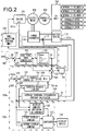
- FIG. 2 is a view showing a configuration of the hydraulic excavator according to the present embodiment.
- An engine 101 and an electric motor 102 are mechanically coupled to each other so that they rotate at the same rotational speed.
- a hydraulic pump 103 is mechanically coupled to the electric motor 102 and driven by means of the engine 101 and the electric motor 102 to discharge hydraulic oil.
- the hydraulic oil discharged from the hydraulic pump 103 is distributed by a control valve unit 104 based on operation of the variety of operating members performed by the operator, so that the hydraulic oil is supplied to the boom cylinder 3a, the arm cylinder 3b, the bucket cylinder 3c, a swing motor 3d for swinging for driving the swing mechanism 1d, and right and left travel motors 3e, 3e in order to drive the actuators 3a through 3e.
- a power converter 110 converts DC power from the rechargeable battery device 111 to AC power, which is then output to the electric motor 102, or the power converter 110 converts AC power from the electric motor 102 to DC power, which is then output to the battery device 111.
- the battery device 111 is a power source for supplying power to the electric motor 102 and is provided with a plurality of battery elements such as capacitors or secondary batteries.
- the electric motor 102 is a three-phase synchronous electric motor having a built-in permanent magnet, for example, and is driven by the three-phase AC power that is converted by the power converter 110, in order to generate a rotational torque.
- the electric motor 102 is also driven by the engine 101 so as to function as a generator for generating the three-phase AC power.
- the electric motor 102 operates as a generator, the AC power output from the electric motor 102 is converted into DC power by the power converter 110 so that the battery device 111 is charged with the DC power converted by the power converter 110.
- the control device is configured to include a main controller 100a, an engine controller 100b, and a display controller 100c.
- Each controller 100a, 100b, 100c is configured to include a processing unit having CPUs, ROMs and RAMs that are storage devices, and other peripheral circuits, and others.
- the main controller 100a comprises a state of charge controller 125, a minimum value selecting circuit 126, a charging request limiter 127, an average charging/discharging current calculator 128, an electric motor torque limiter 141, an adder-subtractor 123, and a subtractor 124.
- the engine controller 100b includes a fuel injection control unit 129, a rotational speed controller 121, an engine torque limiter 122, and a subtractor 120.
- the display controller 100c includes a display content switching determiner 130 and a switcher 133.
- a rotational speed setting dial 140 is connected to the engine controller 100b so that a rotational speed command value N* corresponding to the rotational speed set by the operator may be input.
- An engine speed detector 101a that detects a rotational speed N of the engine 101 is connected to the engine controller 100b, so that a signal corresponding to the rotational speed N of the engine 101 detected by the engine rotating detector 101a may be input.
- a current detector 113 is also connected to the main controller 100a.
- the current detector 113 detects charging current and discharging current (hereinafter, referred to as charging/discharging current) that flow into and out of the battery device 111, so that the signal corresponding to the charging/discharging current Ib detected by the current detector 113 may be input.
- a SOC detector 111a is connected to the main controller 100a.
- the SOC detector 111a detects a state of charge SOC of the battery device 111, so that the signal corresponding to the SOC detected by the SOC detector 111a may be input.
- the signal corresponding to the state of charge SOC which is input to the main controller 100a, is also input to the display controller 100c via the main controller 100a.
- a display device 134 is connected to the display controller 100c so that display images of the display controller 134 are controlled according to the signal output from the display controller 100c.
- the subtractor 120 subtracts the rotational speed N detected by the engine speed detector 101a from the rotational speed command value N* output from the rotational speed setting dial 140, in order to determine a speed deviation ⁇ N between N* and N, which is then output to the rotational speed controller 121.
- the rotational speed controller 121 determines a torque command value T so that the speed deviation ⁇ N is 0, i.e. determines the torque command value T so that the rotational speed N is equal to the rotational speed command value N*, and outputs the torque command value T to the engine torque limiter 122.
- the torque command value T is also output to the adder/subtractor 123.
- a torque limiting property Tt is stored in a storage device of the engine controller 100b in a form of a look-up table.
- the torque limiting property Tt is a property representing the maximum engine torque TEmax that is an upper limit value of the output torque for the torque command value T.
- the engine torque limiter 122 refers to the torque limiting property Tt and calculates the maximum engine torque TEmax for the input torque command value T.
- the engine torque limiter 122 compares the calculated maximum engine torque TEmax and the input torque command value T and selects the smaller one of these in order to output the selected value to the fuel injection control unit 129, as the engine torque command value TE.
- the engine torque command value TE is limited to be equal to or smaller than the maximum engine torque TEmax.
- the engine torque command value TE is also output to the adder/subtractor 123.
- the fuel injection control unit 129 controls a fuel injection device (not shown) to determine a fuel injection quantity and the like so that an output torque of the engine 101 (hereinafter, also referred to as an engine torque) is equal to the engine torque command value TE.
- the subtractor 124 subtracts the state of charge SOC detected by the SOC detector 111a from the state of charge command value SOC* from a battery controller (not shown) and determines a deviation ⁇ SOC between SOC* and SOC, and outputs it to the SOC controller 125.
- the state of charge command value SOC* is a constant value that corresponds to the state of charge of 80%.
- the SOC controller 125 determines a first power generation torque request value TG1 so that the deviation ⁇ SOC is 0, i.e. the state of charge SOC is equal to the state of charge command value SOC*, and outputs the first power generation torque request value TG1 to the minimum value selecting circuit 126. If the state of charge command value SOC* is larger than the state of charge SOC, the first power generation torque request value TG1 is a positive value, while if the state of charge command value SOC* is smaller than the state of charge SOC, the first power generation torque request value TG1 is a negative value.
- the average charging/discharging current calculator 128 calculates an average charging/discharging current Iave that is an average value of the charging/discharging current Ib flowing into and out of the battery device 111 detected by the current detector 113.
- the average charging/discharging current calculator 128 determines the average charging/discharging current Iave by averaging the magnitude of the charging/discharging current Ib with a first low-pass filter and outputs it to the charging request limiter 127.
- the charging/discharging current Iave is also output to the display content switching determiner 130.
- a moving average method or a method of calculating the average value at a predetermined time interval may be employed as the method of determining the average charging/discharging current Iave.
- a mean square value may be used instead of the average charging/discharging current Iave, and electric power may be used instead of electric current.
- the charging request limiter 127 calculates a power generation torque request TGlim and outputs it to the minimum value selecting circuit 126.
- the average charging/discharging current Iave is an indicator that indicates a degree of deterioration of the battery device 111 and the average charging/discharging current Iave is a determination value used for selecting whether the magnitude of the power generation torque request limit value TGlim corresponding to the limit value of the charging current of the battery device 111 is set to 0 or the maximum generator torque TGmax. Details of operation of the charging request limiter 127 will be described hereinafter.
- the minimum value selecting circuit 126 compares the first power generation torque request value TG1 and the power generation torque request limit value TGlim and select the smaller one of these and outputs the selected value as the second power generation torque request value TG2.
- the adder/subtractor 123 subtracts the engine torque command value TE and the second power generation torque request value TG2 from the torque command value T to determine the electric motor torque command value TM and outputs it to the electric motor torque limiter 141. If the electric motor torque command value TM is a positive value, the electric motor 102 is driven by the power supplied from the battery device 111. On the other hand, if the electric motor torque command value TM is a negative value, the electric motor 102 is driven as a generator by means of the engine 101. It will be noted that since the engine torque command value TE is equal to or lower than the torque command value T, the electric motor torque command value TM is larger than the value of which the sign of the second power generation torque request value TG2 is inverted. In other words, if the electric motor torque command value TM is a negative value, the magnitude of the electric motor torque command value TM is smaller than the magnitude of the power generation torque request limit value TGlim.
- the electric motor torque limiter 141 compares the input electric motor torque command value TM and the maximum electric motor torque TMmax to select the smaller one of these and outputs the selected value to the power converter 110, as the electric motor torque command value TM.
- the electric motor torque command value TM is limited to be equal to or less than the maximum electric motor torque TMmax.
- the maximum electric motor torque TMmax is a positive value and is determined under the consideration of an acceptable torque of the electric motor 102 in case that the electric motor 102 is driven by the power of the battery device 111.
- the maximum electric motor torque TMmax is previously stored in the storage device of the main controller 100a.
- the discharging current of the battery device 111 is limited to be equal to or lower than the maximum discharging current required for obtaining the maximum electric motor torque TMmax.
- a discharging current limit value that is set for limiting the discharging current of the battery device 111 is set based upon the maximum electric motor torque TMmax. It will be noted that only a case where the electric motor torque command value TM input to the electric motor torque limiter 141 is smaller than the maximum electric motor torque TMmax will be described in this specification. In other words, the electric motor torque command value output from the electric motor torque limiter 141 is the same as the electric motor torque command value TM input to the electric motor torque limiter 141.
- the power converter 110 controls the electric motor 102 so that the output torque of the electric motor 102 (hereinafter, also referred to as an electric motor torque) is equal to the electric motor torque command value TM.
- the power converter 110 has a plurality of switching elements for converting DC power into three-phase AC power, and a control unit that performs a PWM control on switching of these switching elements so that the electric current flowing into the electric motor 102 is consistent with the electric current command corresponding to the electric motor torque command value TM.
- the control unit of the power converter 110 controls the switching elements to convert the DC power output from the battery device 111 into the three-phase AC power in order to drive the electric motor 102.
- the control unit controls the switching elements to convert the three-phase AC power output from the electric motor 102 into the DC power in order to charge the battery device 111.
- the display device 134 is a monitor that displays information for the operator to know the state of the construction machine.
- the display device 134 displays either a first display content 131 or a second display content 132 that is selected by a switcher 133, based on a switching signal output from the display content switching determiner 130.
- the first display content 131 is a display content that represents information such as the temperature of an engine coolant or the engine rotational speed and the first display content 131 is set based on the information from a coolant temperature detector (not shown) or the engine speed detector 101a.
- the second display content 132 is a display content that includes at least the state of charge SOC of the battery device 111 and the second display content 132 is set based on a signal corresponding to the state of charge SOC detected by the SOC detector 111a.
- the signal corresponding to the state of charge SOC detected by the SOC detector 111a and the signal corresponding to the average charging/discharging current Iave calculated by the average charging/discharging current calculator 128 are input to the display content switching determiner 130.
- the display content switching determiner 130 determines whether the average charging/discharging current Iave is equal to or higher than a threshold It and the state of charge SOC is equal to or lower than a threshold SOCt or not. If the average charging/discharging current Iave is equal to or higher than the threshold It and the state of charge SOC is equal to or lower than the threshold SOCt, the display content switching determiner 130 outputs a second switching signal to the switcher 133, the signal switching the image to be displayed on a display screen of the display device 134 from the first display content 131 to the second display content 132.
- the threshold SOCt and the threshold It are previously stored in the storage device.
- the threshold SOCt is a constant value that corresponds to the state of charge of 40%, for example.
- the threshold It is the same as a second threshold I2 described hereinafter. If the average charging/discharging current Iave is lower than the threshold It or if the state of charge SOC is higher than the threshold SOCt, the display content switching determiner 130 outputs a first switching signal to the switcher 133, the signal switching the image to be displayed on the display screen of the display device 134 from the second display content 132 to the first display content 131.
- the switcher 133 switches the image to be displayed on the display device 134 to the second display content 132. Thereby, the content including the state of charge SOC is displayed on the display device 134. If the first switching signal is input, the switcher 133 switches the image to be displayed on the display device 134 to the first display content 131. Thereby, the information such as the temperature of the engine coolant or the engine rotational speed is displayed on the display device 134.
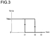
- FIG. 3 is a view showing the relationship between the average charging/discharging current Iave and the power generation torque request limit value TGlim. If the average charging/discharging current Iave is equal to or lower than a first threshold I1 (Iave ⁇ I1), the charging request limiter 127 sets the power generation torque request limit value TGlim to the maximum generator torque TGmax. If the average charging/discharging current Iave is equal to or higher than a second threshold I2 (Iave ⁇ I2), the charging request limiter 127 sets the power generation torque request limit value TGlim to 0.
- a first threshold I1 Iave ⁇ I1
- Ia second threshold I2 Iave ⁇ I2
- the power generation torque request limit value TGlim has hysteresis characteristics. Once the power generation torque request limit value TGlim is set to 0, it remains 0 until the average charging/discharging current Iave is equal to or lower than the first threshold I1. When the average charging/discharging current Iave is equal to or lower than the first threshold I1, the magnitude of the power generation torque request limit value TGlim is changed from 0 to the maximum generator torque TGmax. Similarly, once the power generation torque request limit value TGlim is set to the maximum generator torque TGmax, it remains TGmax until the average charging/discharging current Iave is equal to or higher than the second threshold I2.
- the magnitude of the power generation torque request limit value TGlim is changed from TGmax to 0.
- the maximum generator torque TGmax has a positive value and is determined under the consideration of an acceptable torque of the electric motor 102 in case that the electric motor 102 is driven as a generator by means of the engine 101.
- a third threshold I3 in the figure is determined under the consideration of the value of the average charging/discharging current Iave above which a desired service life could not be ensured due to a rapid deterioration of the battery device 111.
- the third threshold is previously stored in the storage device. In other words, by controlling the charging/discharging current so that the average charging/discharging current Iave is equal to or lower than the third threshold I3, the desired service life of the battery device 111 can be ensured.
- the first threshold I1 and the second threshold I2 are determined to have a smaller value than that of the third threshold, with the magnitude relationship I1 ⁇ I2 ⁇ I3. They are previously stored in the storage device.
- the electric motor torque command value TM output from the adder/subtractor 123 is equal to the value of which the sign of the second power generation torque request value TG2 output from the minimum value selecting circuit 126 as shown in FIG. 2 .
- the upper limit of the second power generation torque request value TG2 is limited to the power generation torque request limit value TGlim. Therefore, the minimum value of the electric motor torque command value TM is -TGlim and the charging current flowing into the battery device 111 is limited.
- a charging current limit value that is set for limiting the charging current of the battery device 111 is set based upon the power generation torque request limit value TGlim is.
- the charging request limiter 127 has a function of changing the magnitude of the charging/discharging current limit value based on the average charging/discharging current Iave.
- the difference ⁇ C is larger than the difference ⁇ D ( ⁇ C > ⁇ D).
- the maximum electric motor torque which corresponds to the discharging current limit value in the situation where the electric motor 102 is driven by the power of the battery device 111, is TMmax, regardless of the magnitude of the average charging/discharging current Iave.
- the power generation torque request limit value TGlim which corresponds to the charging current limit value in the situation where the electric motor 102 is driven by the engine 101, is the maximum generator torque TGmax if the average charging/discharging current Iave is equal to or lower than the first threshold I1, and 0 if the average charging/discharging current Iave is equal to or higher than the second threshold I2.
- the power generation torque request limit value TGlim 0, which corresponds to the charging/discharging current limit value in case that the average charging/discharging current Iave is equal to or higher than the second threshold, is smaller than the maximum electric motor torque TMmax, which corresponds to the discharging current limit value in case that the average charging/discharging current Iave is equal to or higher than the second threshold I2.
- FIG. 4 through FIG. 7 are schematic timing charts showing operation of the control device for a pump torque TL of the hydraulic pump 103, assuming that the excavation is performed.
- Each figure shows operation of the control device in case that tasks with high hydraulic load (for example, the excavating operation or the bucket lifting-up operation) and tasks with low hydraulic load (for example, the swinging operation and the soil discharging operation) are alternately performed in a unit period.
- tasks with high hydraulic load i.e. tasks where output of the hydraulic pump 103 is large
- tasks with low hydraulic load i.e. tasks where output of the hydraulic pump 103 is small
- the unit period is a period from a time point ts to a time point te in the following description.
- FIG. 4 shows a task condition where the average value of the hydraulic load per unit period is smallest (hereinafter, referred to as average light load task).
- the average values of the hydraulic load per unit period in FIG. 5 , FIG. 6 , and FIG. 7 vary from lower to higher in this order of figures.
- FIG. 5 shows a task condition (hereinafter, referred to as average medium load task) where the average value of the hydraulic load per unit period is larger than that of the average light load task.
- FIG. 5 shows a task condition (hereinafter, referred to as average medium load task) where the average value of the hydraulic load per unit period is larger than that of the average light load task.
- FIG. 6 shows a task condition (hereinafter, referred to as average heavy load task) where the average value of the hydraulic load per unit period is larger than that of the average medium load task.
- FIG. 7 shows a task condition (hereinafter, referred to as average superheavy load task) where the average value of the hydraulic load per unit period is larger than that of the average heavy load task. It will be noted that the average value of the hydraulic load per unit period becomes higher as the output of the hydraulic pump 103 in the heavy load task is increased or as a time proportion of the heavy load task in the unit period is increased.
- the abscissa represents elapsed time.
- the ordinate in (a) represents the rotational speed N of the engine 101 and the electric motor 102
- the ordinate in (b) represents an input torque (hereinafter, also referred to as a pump torque) of the hydraulic pump 103 representing the hydraulic load.
- the ordinate in (c) represents the magnitude of the torque command value T (dashed line) and the magnitude of the engine torque command value TE (solid line).
- the ordinate in (d) represents the electric motor torque command value TM and the ordinate in (e) represents the state of charge SOC.
- the ordinate in (f) represents the second power generation torque request value TG2, the ordinate in (g) represents the power generation torque request limit value TGlim, and the ordinate in (h) represents the average charging/discharging current Iave.
- FIG. 5 is a timing chart in which the state of charge SOC of the battery device 111 is equal to the state of charge command value SOC*, and a condition (at a time point t0) where the average charging/discharging current Iave is smaller than the first threshold I1 is set as the initial condition. It will be noted that TGlim is set to TGmax at the time point t0.
- the engine torque command value TE is limited to the maximum engine torque TEmax in the period from the time point t202 to the time point t203
- the output torque of the electric motor 102 increases with the increase in the electric motor torque command value TM, so that the rotational speed N is controlled to be equal to the rotational speed command value N* as shown in (a) in FIG. 5 .
- the state of charge SOC of the battery device 111 decreases as shown in (e) in FIG. 5 .
- the deviation ⁇ SOC output from the subtractor124 increases. Accordingly, the first power generation torque request value TG1 increases.
- the average charging/discharging current Iave is equal to or lower than the first threshold I1 as shown in (h) in FIG. 5 . Therefore, as shown in (g) in FIG. 5 , the power generation torque request limit value TGlim is set to the maximum generator torque TGmax.
- the second power generation torque request value TG2 is equal to the first power generation torque request value TG1 and increases in the same way as the first power generation torque request value TG1.
- the electric motor torque command value TM output from the adder/subtractor 123 decreases.
- the rotational speed N decreases so that the speed deviation ⁇ N output from the subtractor 120 increases, which results in an increase in the torque command value T as shown in (c) in FIG. 5 . Consequently, the electric motor torque command value TM is controlled to remain almost constant.
- the electric motor 102 does not operate as a generator, but is driven by the power from the battery device 111 and the hydraulic pump 103 is driven by means of the engine 101 and the electric motor 102, even if the state of charge SOC decreases. Even if the state of charge SOC of the battery device 111 decreases, the rotational speed N does not decrease because the hydraulic pump 103 is supplied with enough power during the excavating task.
- the average charging/discharging current Iave increases as shown in (h) in FIG. 5 so long as the electric motor 102 is driven by the power discharged from the battery device 111, because the discharging current flows into the battery device 111. However, in the average medium load task, the increase amount of the average charging/discharging current Iave is small because the electric current value is small.
- the deviation ⁇ SOC output from the subtractor 124 decreases.
- the second power generation torque request value TG2 decreases as shown in (f) in FIG. 5 and the electric motor torque command value TM increases as shown in (d) in FIG. 5 .
- the absolute value of the electric motor torque command value TM having a negative value decreases, so that the generated power decreases gradually.
- the electric motor 102 is driven by means of the engine 101 to operate as a generator, so that the battery device 111 is charged.
- the electric motor 102 operates as a generator, the average charging/discharging current Iave increases as shown in (h) in FIG. 5 because the charging current flows into the battery device 111.
- the increase amount of the average charging/discharging current Iave is small because the electric current value is small.
- the second power generation torque request value TG2 is 0 as shown in (f) in FIG. 5 and the electric motor torque command value TM is also 0 as shown in (d) in FIG. 5 .
- the rotational speed N is controlled by the rotational speed controller 121 to be equal to the rotational speed command value N*.
- the engine torque is in balance with the pump torque TL.
- the operations of the control device at the time points t211, t212, t213, t214 are the same as that at the time points t201, t202, t203, t204.
- the operations between the time points t211 and t221 are the same as that between the time points t201 and t211.
- the same operations are repeatedly performed after the time point t221, as well.
- the control device causes the electric motor 102 to be operated by the power of the battery device 111 and causes the hydraulic pump 103 to be driven by means of the electric motor 102 and the engine 101. Furthermore, if the pump torque TL is equal to or lower than the maximum engine torque TEmax, the control device causes the electric motor 102 to operate as a generator by means of the engine 101 in order to control the state of charge SOC of the battery device 111 to be equal to the state of charge command value SOC*.
- the operations of the control device in the average light load task ( FIG. 4 ) is the same as the operations of the control device in the average medium load task ( FIG. 5 ), as described above.
- the time points t101, t102, t103, t104, t111, t112, t113, t114, t121 shown in FIG. 4 correspond to the time points t201, t202, t203, t204, t211, t212, t213, t214, t221 shown in FIG. 5 , respectively.
- the maximum value of the pump torque TL is small.
- the maximum value of the electric motor torque command value TM in case that the electric motor 102 operates by the power of the battery device 111 and the maximum value of the absolute value of the electric motor torque command value TM in case that the electric motor 102 operates as a generator are smaller than that in the average medium load task.
- FIG. 6 is a timing chart in which the state of charge SOC of the battery device 111 is smaller than the state of charge command value SOC*, and a condition (at a time point t0) where the average charging/discharging current Iave is larger than the first threshold I1 and smaller than the second threshold I2 is set as the initial condition.
- the power generation torque request limit value TGlim is set to TGmax at the time point t0.
- the first power generation torque request value TG1 output from the SOC controller 125 is a positive value.
- the charging request limiter 127 outputs the maximum generator torque TGmax as the power generation torque request limit value TGlim.
- the engine torque limiter 122 Since the torque command value T is equal to or higher than the maximum engine torque TEmax as shown by a dashed line in (c) in FIG. 6 , the engine torque limiter 122 outputs the maximum engine torque TEmax as the engine torque command value TE.
- the electric motor torque command value TM is a negative value and the electric motor 102 thus operates as a generator.
- the rotational speed N decreases.
- the torque command value T is increased to exceed the maximum engine torque TEmax by the rotational speed controller 121. Therefore, the electric motor torque command value TM is increased by the adder/subtractor 123. In other words, the magnitude of the absolute value of the electric motor torque command value TM decreases.
- the rotational speed N is controlled to be equal to the rotational speed command value N*.
- the control device in the present embodiment regulates the amount of power generation of the electric motor 102 and controls the rotational speed N so as to be equal to the rotational speed command value N*, depending on the pump torque TL.
- the electric motor torque command value TM output from the adder/subtractor 123 increases.
- the value of the electric motor torque command value TM changes from a negative value to a positive value
- the power generating operation of the electric motor 102 is finished and the electric motor 102 is driven by the power from the battery device 111.
- the electric motor 102 compensates for the shortfall of the maximum engine torque TEmax to the pump torque TL, so that the rotational speed N is controlled to be equal to the rotational speed command value N*.
- the maximum value of the pump torque TL in the period from the time point t301 to the time point t303 in FIG. 6 is larger than the maximum value of the pump torque TL in the period from the time point t201 to the time point t203 in FIG. 5 .
- the time points t201 to t221 correspond to the time points t301 to 321, respectively, and they represent the same change in time.
- the output of the hydraulic pump 103 in the unit period is larger than that in the average medium load task.
- the average heavy load task has a higher average value of the hydraulic load (i.e. a higher output of the hydraulic pump 103) per unit period than that of the average medium load task.
- the electric motor torque command value TM output from the adder/subtractor 123 decreases as shown in (d) in FIG. 6 .
- the electric motor torque command value TM becomes a negative value
- the electric motor 102 performs the power generating operation to charge the battery device 111. Therefore, as shown in (e) in FIG. 6 , the state of charge SOC of the battery device 111 increases.
- the charging current flows into the battery device 111 while the electric motor 102 operates as a generator, and the discharging current flows out of the battery device 111 while the electric motor 102 is driven by the power discharged from the battery device 111. Therefore, as shown in (h) in FIG. 6 , in the period from the time point t0 to the time point t304, the average charging/discharging current Iave increases with elapse of time.
- the charging request limiter 127 When the average charging/discharging current Iave is equal to or larger than the second threshold I2 at the time point t304, the charging request limiter 127 outputs 0 as the power generation torque request limit value TGlim as shown in 6(g) in FIG. 6 . As a result, the second power generation torque request value TG2 output from the minimum value selecting circuit 126 is also 0, as shown in (f) in FIG. 6 .
- the charging of the battery device 111 is stopped and the increase in the state of charge SOC is stopped (see (e) in FIG. 6 ). Since the electric current no longer flows into the battery device 111, the average charging/discharging current Iave begins to decrease from the time point t304, as shown in (h) in FIG. 6 . In other words, if the average charging/discharging current Iave increases to exceed the second threshold I2, the charging to the battery device 111 is limited and the average charging/discharging current Iave, which has increased until this point, turns to decrease.
- the state of charge SOC of the battery device 111 decreases as shown in (e) in FIG. 6 .
- the power generation torque request limit value TGlim is set to 0. Because the first power generation torque request value TG1 (not shown) is larger than the power generation torque request limit value TGlim, the second power generation torque request value TG2 is equal to the power generation torque request limit value TGlim, i.e. 0, as shown in (f) in FIG. 6 .
- the rotational speed N increases slightly as shown in (a) in FIG. 6 so that the absolute value of the speed deviation ⁇ N between the rotational speed N and the rotational speed command value N* increases (N > N*).
- the torque command value T decreases as shown in (c) in FIG. 6 .
- the electric motor torque command value TM output from the adder/subtractor 123 decreases as shown in (d) in FIG. 6 .
- the second power generation torque request value TG2 is equal to the power generation torque request limit value TGlim and limited to 0.
- the electric motor torque command value TM would not become a negative value. In other words, the electric motor 102 does not perform the power generating operation. If such a situation continues that no charging current flows into the battery device 111, the average charging/discharging current Iave decreases with elapse of time as shown in (h) in FIG. 6 .
- the charging request limiter 127 sets the power generation torque request limit value TGlim to the maximum generator torque TGmax as shown in (g) in FIG. 6 . Therefore, the maximum generator torque TGmax is output as the second power generation torque request value TG2 from the minimum value selecting circuit 126, as shown in (f) in FIG. 6 . Accordingly, the electric motor torque command value TM becomes a negative value as shown in (d) in FIG. 6 and the electric motor 102 thus operates as a generator, so that the charging to the battery device 111 is resumed from the time point t315.
- the operations from the time point t315 to the time point t321 are the same as the operations from the time point t0 to the time point t301. After the time point t321, the same operations are repeatedly performed as that after the time point t301.
- the control device causes the electric motor 102 to be operated by the power of the battery device 111 if the pump torque TL exceeds the maximum engine torque TEmax. If the pump torque TL is equal to or lower than the maximum engine torque TEmax and the second power generation torque request value TG2 is the maximum generator torque TGmax, the control device causes the electric motor 102 to operate as a generator by means of the engine 101, so that the state of charge SOC of the battery device 111 is increased towards the state of charge command value SOC*.
- the charging request limiter 127 sets the power generation torque request limit value TGlim to 0. Therefore, even if the pump torque TL is equal to or lower than the maximum engine torque TEmax (from the time point t304 to the time point t312, and from the time point t313 to the time point t315), the power generating operation of the electric motor 102 is prohibited if the power generation torque request limit value TGlim is 0.
- the hydraulic pump 103 if the pump torque TL exceeds the maximum engine torque TEmax, the hydraulic pump 103 is supplied with enough power with the torque assistance of the electric motor 102. Thereby, a decrease in the rotational speed N can be prevented in the excavating task.
- FIG. 7 is a timing chart in which the state of charge SOC of the battery device 111 is smaller than the state of charge command value SOC*, and a condition (at a time point t0) where the average charging/discharging current Iave is larger than the first threshold I1 and smaller than the second threshold I2 is set as the initial condition. It will be noted that TGlim is set to 0 at the time point t0.
- the pump torque TL begins to increase at a time point t401 (see (b) in FIG. 7 ), the torque command value T exceeds the maximum engine torque TEmax at a time point t402 (see (c) in FIG. 7 ), and the pump torque TL begins to decrease at a time point t403 (see (b) in FIG. 7 ).
- the operations of the control device at the time points t411, t412, t413 are the same as that at the time points t401, t402, t403.
- the operations between the time points t411 and t421 are the same as that between the time points t401 and t411. The same operations are repeatedly performed after the time point t421, as well.
- the pump torque TL which represents the hydraulic load
- the electric motor torque is needed to be larger.
- the average charging/discharging current Iave exceeds the second threshold I2 every time when an operation is performed by the operator (at the time point t403 and t413). Therefore, even if the charging of the electric motor 102 is prohibited, the average charging/discharging current Iave would not decrease to the first threshold I1 before the next operation is performed.
- the charging request limiter 127 continues to output 0 as the power generation torque request limit value TGlim.
- the control device in the average superheavy load task, the power generating operation of the electric motor 102 is prohibited and the charging of the battery device 111 is not performed. Therefore, although the average value of the hydraulic load per unit period in the average superheavy load task is higher than that in the average heavy load task, the average charging current of the battery device 111 is set to 0, i.e. the charging is not performed, so that the increase amount of the average charging/discharging current Iave of the battery device 111 is suppressed. As a result, performance of the battery device 111 can be maintained over a long period.
- the discharging of the battery device 111 is performed depending on the tasks, and the charging is also performed in order to keep the state of charge SOC at the state of charge command value SOC*.
- the discharging current of the battery device 111 is larger than the average light/medium load task. Therefore, the average charging/discharging current Iave is equal to or higher than the second threshold I2, so that the charging of the battery device 111 is limited.
- the discharging current of the battery device 111 is smaller than that in the average superheavy load task.
- the average charging/discharging current Iave is equal to or lower than the first threshold I1 by limiting the charging, even though the charging of the battery device 111 is also performed. In the average superheavy load task, the charging of the battery device 111 is not performed.
- the control device controlling the charging/discharging of the battery device 111 in the configuration described above controls the charging/discharging of the battery device 111 in the configuration described above, the relationship between the discharging current that flows into the battery device 111 per unit period (hereinafter, average discharging current) and the charging current that flows into the battery device 111 per unit period (hereinafter, average charging current) in each task is as follows.
- FIG. 8 is a schematic view showing the relationship between the average discharging current and the average charging current.
- the abscissa represents the average discharging current and the ordinate represents the average charging current.
- the average discharging current of the battery device 111 is larger as the average value of the magnitude of the hydraulic load per unit period is higher, i.e. the maximum value of the pump torque TL in (b) in FIG. 4 , (b) in FIG. 5 , (b) in FIG.6 or (b) in FIG. 7 is higher or the time period during which the pump torque TL is as the maximum value is longer. Therefore, the average discharging current in the abscissa may be replaced by the average value of the hydraulic load.
- the abscissa may be replaced by the average value of the positive parts of the electric motor torque command value TM per unit period in (d) in FIG. 4 , (d) in FIG. 5 , (d) in FIG.6 or (d) in FIG.7 , while the ordinate may be replaced by the value of which the sign of the average value of the negative parts of the electric motor torque command value TM per unit period in (d) in FIG. 4 , (d) in FIG. 5 , (d) in FIG.6 or (d) in FIG.7 .
- the average values per unit period is shown, the same trend can be observed also in the accumulated values per unit period.
- the average discharging current and the average charging current are equal to each other because the battery device 111 is charged by the same amount as that it is discharged.
- the average charging current of the battery device 111 per unit period increases while the average discharging current of the battery device 111 per unit period increases, as shown in FIG. 8 .
- the average charging current of the battery device 111 per unit period increases with the increase in the average value of the hydraulic load per unit period. That is, in the average medium load task (see FIG. 5 ) where the average value of the hydraulic load per unit period is higher than that in the average light load task (see FIG. 4 ), the average charging current of the battery device 111 is higher.
- the average charging current of the battery device 111 per unit period decreases as the average discharging current of the battery device 111 per unit period increases, as shown in the figure.
- the average charging current of the battery device 111 per unit period decreases with the increase in the average value of the hydraulic load per unit period. That is, in the average superheavy load task (see FIG. 7 ) where the average value of the hydraulic load per unit period is higher than that in the average heavy load task (see FIG. 6 ), the average charging current of the battery device 111 is lower.
- the average charging/discharging current Iave can be suppressed by limiting the charging, while performing the discharging required for the task.
- performance of the battery device 111 can be maintained for a long time, while ensuring workability.
- the control device is configured to display images including information of the state of charge on the display screen of the display device 134 in order to inform the operator of the fact that the task corresponding to the average heavy load task or the average superheavy load task is continuously performed so that the state of charge SOC of the battery device 111 decreases to the threshold SOCt.
- FIG. 9 is a timing chart showing operation of the control device in case that the average heavy load task is continuously performed in such a manner that the state of charge gradually decreases with elapse of time.
- FIG. 9 shows a timing chart in case that a task having the same level of load as that of the average heavy load task shown in FIG. 6 is performed for a long time.
- the abscissa in FIG. 9 represents elapsed time.
- the ordinate in (a) in FIG. 9 represents the rotational speed N of the engine 101 and the electric motor 102, and the ordinate in (b) in FIG. 9 represents the pump torque TL representing the hydraulic load.
- FIG. 9 represents the magnitude of the torque command value T shown by a dashed line and the magnitude of the engine torque command value TE shown by a solid line.
- the ordinate in (d) in FIG. 9 represents the electric motor torque command value TM and the ordinate in (e) in FIG. 9 represents the state of charge SOC.
- the ordinate in (f) in FIG. 9 represents the second power generation torque request value TG2
- the ordinate in (g) in FIG. 9 represents the power generation torque request limit value TGlim
- the ordinate in (h) in FIG. 9 represents the average charging/discharging current Iave.
- (i) in FIG. 9 shows whether the first display content 131 or the second display content 132 is to be displayed on the display screen of the display device 134.
- the state of charge SOC of the battery device 111 decreases with elapse of time.
- the display content switching determiner 130 outputs a second switching signal to the switcher 133. Thereby, the image to be displayed on the display screen of the display device 134 is switched from the first display content 131 to the second display content 132.
- the second display content 132 includes at least information of the state of charge SOC of the battery device 111, the operator will know that the state of charge SOC of the battery device 111 decreases. Looking at the display content, the operator can regulate the way of working, so that the operator can avoid a situation where the torque assistance of the electric motor 102 suddenly stops during the task and the task has to be interrupted.
- the magnitude of the power generation torque request limit value TGlim corresponding to the charging current limit value that is set for limiting the charging current of the battery device 111 becomes the maximum generator torque TGmax if the average charging/discharging current Iave is equal to or lower than the first threshold I1, and it becomes 0 if the average charging/discharging current Iave is equal to or higher than the second threshold I2.
- the present invention is not limited to this configuration.
- the power generation torque request limit value TGlim corresponding to the charging current limit value in case that the average charging/discharging current Iave is equal to or higher than the second threshold I2 may be set to a value that is higher than 0 and lower than the maximum generator torque TGmax.
- the maximum electric motor torque TMmax which corresponds to the discharging current limit value
- the discharging current limit value is a constant value, regardless of the average charging/discharging current Iave.
- the present invention is not limited to this configuration. It may be also possible that the magnitude of the discharging current in case that the average charging/discharging current Iave is equal to or higher than the second threshold I2 is smaller than the magnitude of the discharging current limit value in case that the average charging/discharging current Iave is equal to or lower than the first threshold I1, in the same manner as the charging current limit value.
- the magnitude of the charging current limit value is set to be smaller than the magnitude of the discharging current magnitude in case that the average charging/discharging current Iave is equal to or higher than the second threshold I2. Furthermore, it is preferable that limit values are set in such a manner that the difference between the magnitude of the charging current limit value in case that the average charging/discharging current Iave is equal to or lower than the first threshold I1 and the magnitude of the charging current limit value in case that the average charging/discharging current Iave is equal to or higher than the second threshold I2 is larger than the difference between the magnitude of the discharging current limit value in case that the average charging/discharging current Iave is equal to or lower than the first threshold I1 and the magnitude of the discharging current limit value in case that the average charging/discharging current Iave is equal to or higher than the second threshold I2.
- the average charging/discharging current Iave is used as a determination value that is an indicator indicating a degree of deterioration of the battery device 111 in order to determine whether the magnitude of the charging current limit value of the battery device 111 should be changed or not.
- the temperature of the battery device 111 may be used as the determination value that is the indicator indicating the degree of deterioration of the battery device 111. If the temperature of the battery device 111 becomes too high, the battery device 111 tends to be rapidly degraded so that the service life of the battery device 111 is shortened.
- a temperature detector that detects the temperature of the battery device 111 is provided.
- the charging request limiter 127 is configured to output 0 as the power generation torque request limit value TGlim if the temperature of the battery device 111 is higher than a threshold, and output the maximum generator torque TGmax as the power generation torque request limit value TGlim if the temperature of the battery device 111 is lower than the threshold.
- the service life of the battery device 111 is extended by suppressing a rise in temperature of the battery device 111.
- the engine 101 and the electric motor 102 rotate at the same rotational speed.
- the engine 101 and the electric motor 102 may be coupled via a transmission. In this case, it is necessary to convert the rotational speed command value N*, the rotational speed N, and the like in consideration of a gear ratio.
- the display screen of the display device 134 is switched from the first display content 131 to the second display content 132 if the state of charge SOC of the battery device 111 is equal to or lower than the threshold SOC and the average charging/discharging current Iave is equal to or lower than the threshold It.
- the present invention is not limited to this configuration.
- the display screen of the display device 134 may be switched from the first display content 131 to the second display content 132 if the state of charge SOC of the battery device 111 is equal to or lower than the threshold SOCt, regardless of the average charging/discharging current Iave.
- the thresholds are not limited to that in the embodiment described above.
- the threshold It used for determining whether the switching of the display device 134 should be performed or not and the second threshold I2 used for determining whether the magnitude of the power generation torque request limit value TGlim, which corresponds to the charging current limit value, should be changed from TGmax to 0 or not are the same.
- these thresholds may be different to each other.
- the configuration of the main controller 100a, the engine controller 100b, and the display controller 100c is not limited to that in the embodiment described above.
- Processing means such as the rotational speed controller 121, the charging request limiter 127, the SOC controller 125, the average charging/discharging current calculator 128, and the like may be configured in hardware or implemented as a software which runs on a hardware.
- the present invention is not limited to this.
- the present invention is also applicable to other construction machines such as a wheel loader, a forklift, a telehandler, or a lift truck, for example.
- the present invention is not limited to the embodiments described above, but other forms that are conceivable within the scope of the technical idea of the present invention are encompassed within the scope of the present invention, unless impairing the features of the present invention.
Landscapes
- Engineering & Computer Science (AREA)
- Mechanical Engineering (AREA)
- Transportation (AREA)
- Power Engineering (AREA)
- General Engineering & Computer Science (AREA)
- Life Sciences & Earth Sciences (AREA)
- Sustainable Development (AREA)
- Sustainable Energy (AREA)
- Structural Engineering (AREA)
- Civil Engineering (AREA)
- Mining & Mineral Resources (AREA)
- Chemical & Material Sciences (AREA)
- Combustion & Propulsion (AREA)
- Physics & Mathematics (AREA)
- General Physics & Mathematics (AREA)
- Automation & Control Theory (AREA)
- Hybrid Electric Vehicles (AREA)
- Electric Propulsion And Braking For Vehicles (AREA)
- Charge And Discharge Circuits For Batteries Or The Like (AREA)
- Control Of Vehicle Engines Or Engines For Specific Uses (AREA)
- Operation Control Of Excavators (AREA)
Applications Claiming Priority (1)
| Application Number | Priority Date | Filing Date | Title |
|---|---|---|---|
| JP2015135980A JP6381491B2 (ja) | 2015-07-07 | 2015-07-07 | 建設機械の制御装置 |
Publications (2)
| Publication Number | Publication Date |
|---|---|
| EP3115249A1 true EP3115249A1 (de) | 2017-01-11 |
| EP3115249B1 EP3115249B1 (de) | 2018-12-12 |
Family
ID=55486503
Family Applications (1)
| Application Number | Title | Priority Date | Filing Date |
|---|---|---|---|
| EP16157571.7A Active EP3115249B1 (de) | 2015-07-07 | 2016-02-26 | Steuerungsvorrichtung für die batterie einer hybriden baumaschine |
Country Status (5)
| Country | Link |
|---|---|
| US (1) | US10047501B2 (de) |
| EP (1) | EP3115249B1 (de) |
| JP (1) | JP6381491B2 (de) |
| KR (1) | KR101797847B1 (de) |
| CN (1) | CN106337456B (de) |
Cited By (1)
| Publication number | Priority date | Publication date | Assignee | Title |
|---|---|---|---|---|
| CN121105904A (zh) * | 2025-11-17 | 2025-12-12 | 青州英诺重工机械有限公司 | 电动新能源装载机的电池管理系统 |
Families Citing this family (3)
| Publication number | Priority date | Publication date | Assignee | Title |
|---|---|---|---|---|
| KR102146930B1 (ko) * | 2018-12-11 | 2020-08-21 | 대한민국 | 왕귀뚜라미에서 유래한 항균 펩타이드 테레오그릴루신 3 및 그의 조성물 |
| CN111348555B (zh) * | 2020-01-22 | 2022-02-15 | 中联重科建筑起重机械有限责任公司 | 工程机械控制方法及控制装置 |
| US20230249581A1 (en) * | 2022-02-09 | 2023-08-10 | Nott Corporation | Methods and systems for power management of a vehicle |
Citations (4)
| Publication number | Priority date | Publication date | Assignee | Title |
|---|---|---|---|---|
| EP1383224A1 (de) * | 2001-04-27 | 2004-01-21 | Kabushiki Kaisha Kobe Seiko sho | Hybridkonstruktionsgeräteleistungssteuervorrichtung |
| EP1526627A2 (de) * | 2003-10-20 | 2005-04-27 | Toyota Jidosha Kabushiki Kaisha | Steuergerät für Elektrizitätsladungsmechanismus |
| EP2418504A1 (de) * | 2009-04-01 | 2012-02-15 | Sumitomo Heavy Industries, LTD. | Hybrid-betriebs-maschinen |
| EP2670019A1 (de) * | 2011-01-28 | 2013-12-04 | Sumitomo Heavy Industries, Ltd. | Schaufel |
Family Cites Families (18)
| Publication number | Priority date | Publication date | Assignee | Title |
|---|---|---|---|---|
| JPH05287780A (ja) | 1992-04-07 | 1993-11-02 | Hitachi Constr Mach Co Ltd | 作業車両の暖機制御装置 |
| JP3929387B2 (ja) | 1997-10-13 | 2007-06-13 | トヨタ自動車株式会社 | 二次電池の充放電制御装置 |
| JP3680898B2 (ja) | 1997-10-13 | 2005-08-10 | トヨタ自動車株式会社 | 二次電池の充放電制御装置 |
| JP4305410B2 (ja) | 2004-10-22 | 2009-07-29 | 日産自動車株式会社 | 電流制御装置及び電流制御方法 |
| JP4504940B2 (ja) * | 2006-04-14 | 2010-07-14 | 日立建機株式会社 | 作業車両の状態表示装置 |
| JP4952031B2 (ja) | 2006-04-14 | 2012-06-13 | トヨタ自動車株式会社 | 電源装置および電源装置における入出力制限設定方法並びに車両およびその制御方法 |
| JP4847218B2 (ja) | 2006-06-01 | 2011-12-28 | 日立建機株式会社 | 建設機械の排ガス浄化装置 |
| JP4892057B2 (ja) * | 2007-03-28 | 2012-03-07 | 株式会社小松製作所 | ハイブリッド建設機械の制御方法およびハイブリッド建設機械 |
| JP4618277B2 (ja) * | 2007-07-24 | 2011-01-26 | 株式会社デンソー | 電源マネージメントシステム |
| JP2010025179A (ja) | 2008-07-16 | 2010-02-04 | Hitachi Constr Mach Co Ltd | 走行作業機械の油圧駆動システム |
| JP5225779B2 (ja) | 2008-08-05 | 2013-07-03 | 住友重機械工業株式会社 | 充放電制御方法 |
| JP2010193630A (ja) | 2009-02-18 | 2010-09-02 | Sumitomo Heavy Ind Ltd | 蓄電制御装置及び作業機械 |
| JP5198661B2 (ja) * | 2009-06-25 | 2013-05-15 | 住友重機械工業株式会社 | ハイブリッド型作業機械及び作業機械の制御方法 |
| JP5268853B2 (ja) | 2009-10-08 | 2013-08-21 | 株式会社日立製作所 | ハイブリッド走行制御システム |
| US20130038121A1 (en) * | 2010-04-28 | 2013-02-14 | Nabtesco Corporation | Hybrid Construction Machine Control System |
| CN103189576B (zh) * | 2010-10-15 | 2016-10-12 | 日立建机株式会社 | 工程机械 |
| JP5568533B2 (ja) * | 2011-09-22 | 2014-08-06 | 日立建機株式会社 | 建設機械およびその電池パック |
| US9637006B2 (en) * | 2014-07-31 | 2017-05-02 | Caterpillar Inc. | Power converter for electric hybrid earthmoving machine |
-
2015
- 2015-07-07 JP JP2015135980A patent/JP6381491B2/ja active Active
-
2016
- 2016-02-25 KR KR1020160022654A patent/KR101797847B1/ko not_active Expired - Fee Related
- 2016-02-25 US US15/053,080 patent/US10047501B2/en active Active
- 2016-02-25 CN CN201610104643.XA patent/CN106337456B/zh not_active Expired - Fee Related
- 2016-02-26 EP EP16157571.7A patent/EP3115249B1/de active Active
Patent Citations (5)
| Publication number | Priority date | Publication date | Assignee | Title |
|---|---|---|---|---|
| EP1383224A1 (de) * | 2001-04-27 | 2004-01-21 | Kabushiki Kaisha Kobe Seiko sho | Hybridkonstruktionsgeräteleistungssteuervorrichtung |
| EP1526627A2 (de) * | 2003-10-20 | 2005-04-27 | Toyota Jidosha Kabushiki Kaisha | Steuergerät für Elektrizitätsladungsmechanismus |
| JP2005124353A (ja) | 2003-10-20 | 2005-05-12 | Toyota Motor Corp | 蓄電機構の制御装置 |
| EP2418504A1 (de) * | 2009-04-01 | 2012-02-15 | Sumitomo Heavy Industries, LTD. | Hybrid-betriebs-maschinen |
| EP2670019A1 (de) * | 2011-01-28 | 2013-12-04 | Sumitomo Heavy Industries, Ltd. | Schaufel |
Cited By (1)
| Publication number | Priority date | Publication date | Assignee | Title |
|---|---|---|---|---|
| CN121105904A (zh) * | 2025-11-17 | 2025-12-12 | 青州英诺重工机械有限公司 | 电动新能源装载机的电池管理系统 |
Also Published As
| Publication number | Publication date |
|---|---|
| CN106337456A (zh) | 2017-01-18 |
| US20170009427A1 (en) | 2017-01-12 |
| KR101797847B1 (ko) | 2017-11-14 |
| JP2017020169A (ja) | 2017-01-26 |
| JP6381491B2 (ja) | 2018-08-29 |
| KR20170006245A (ko) | 2017-01-17 |
| CN106337456B (zh) | 2018-10-19 |
| US10047501B2 (en) | 2018-08-14 |
| EP3115249B1 (de) | 2018-12-12 |
Similar Documents
| Publication | Publication Date | Title |
|---|---|---|
| KR101768339B1 (ko) | 하이브리드식 건설 기계 | |
| US9187294B2 (en) | Hybrid construction machine and method for controlling the same | |
| US9540790B2 (en) | Work machine | |
| JP6592187B2 (ja) | ハイブリッド建設機械 | |
| US10315508B2 (en) | Hybrid work machine | |
| JP5758994B2 (ja) | ハイブリッド式掘削機の制御システム | |
| EP1834854A2 (de) | Hybride Baumaschine | |
| US20170291501A1 (en) | Hybrid Construction Machinery | |
| CN103180520B (zh) | 动力传动装置 | |
| EP3115249B1 (de) | Steuerungsvorrichtung für die batterie einer hybriden baumaschine | |
| JPWO2012046788A1 (ja) | ハイブリッド型作業機械 | |
| CN103661359A (zh) | 混合动力式工程机械 | |
| JP2005233164A (ja) | 作業機械の動力源装置 | |
| EP3249115B1 (de) | Hybridbaumaschine | |
| JP6341813B2 (ja) | ハイブリッド式建設機械 | |
| JP2012007336A (ja) | ハイブリッド型建設機械における制御システム | |
| CN105940161A (zh) | 挖土机 | |
| JP5808635B2 (ja) | ハイブリッド式ショベルの制御方法 | |
| JP2025141021A (ja) | 作業機械電力制御装置 | |
| JP2008094531A (ja) | マグネット作業機の制御装置 |
Legal Events
| Date | Code | Title | Description |
|---|---|---|---|
| PUAI | Public reference made under article 153(3) epc to a published international application that has entered the european phase |
Free format text: ORIGINAL CODE: 0009012 |
|
| STAA | Information on the status of an ep patent application or granted ep patent |
Free format text: STATUS: REQUEST FOR EXAMINATION WAS MADE |
|
| 17P | Request for examination filed |
Effective date: 20160330 |
|
| AK | Designated contracting states |
Kind code of ref document: A1 Designated state(s): AL AT BE BG CH CY CZ DE DK EE ES FI FR GB GR HR HU IE IS IT LI LT LU LV MC MK MT NL NO PL PT RO RS SE SI SK SM TR |
|
| AX | Request for extension of the european patent |
Extension state: BA ME |
|
| GRAP | Despatch of communication of intention to grant a patent |
Free format text: ORIGINAL CODE: EPIDOSNIGR1 |
|
| STAA | Information on the status of an ep patent application or granted ep patent |
Free format text: STATUS: GRANT OF PATENT IS INTENDED |
|
| INTG | Intention to grant announced |
Effective date: 20180618 |
|
| GRAS | Grant fee paid |
Free format text: ORIGINAL CODE: EPIDOSNIGR3 |
|
| GRAA | (expected) grant |
Free format text: ORIGINAL CODE: 0009210 |
|
| STAA | Information on the status of an ep patent application or granted ep patent |
Free format text: STATUS: THE PATENT HAS BEEN GRANTED |
|
| AK | Designated contracting states |
Kind code of ref document: B1 Designated state(s): AL AT BE BG CH CY CZ DE DK EE ES FI FR GB GR HR HU IE IS IT LI LT LU LV MC MK MT NL NO PL PT RO RS SE SI SK SM TR |
|
| REG | Reference to a national code |
Ref country code: GB Ref legal event code: FG4D |
|
| REG | Reference to a national code |
Ref country code: CH Ref legal event code: EP |
|
| REG | Reference to a national code |
Ref country code: AT Ref legal event code: REF Ref document number: 1075480 Country of ref document: AT Kind code of ref document: T Effective date: 20181215 |
|
| REG | Reference to a national code |
Ref country code: DE Ref legal event code: R096 Ref document number: 602016007939 Country of ref document: DE |
|
| REG | Reference to a national code |
Ref country code: IE Ref legal event code: FG4D |
|
| REG | Reference to a national code |
Ref country code: NL Ref legal event code: MP Effective date: 20181212 |
|
| REG | Reference to a national code |
Ref country code: LT Ref legal event code: MG4D |
|
| PG25 | Lapsed in a contracting state [announced via postgrant information from national office to epo] |
Ref country code: BG Free format text: LAPSE BECAUSE OF FAILURE TO SUBMIT A TRANSLATION OF THE DESCRIPTION OR TO PAY THE FEE WITHIN THE PRESCRIBED TIME-LIMIT Effective date: 20190312 Ref country code: NO Free format text: LAPSE BECAUSE OF FAILURE TO SUBMIT A TRANSLATION OF THE DESCRIPTION OR TO PAY THE FEE WITHIN THE PRESCRIBED TIME-LIMIT Effective date: 20190312 Ref country code: FI Free format text: LAPSE BECAUSE OF FAILURE TO SUBMIT A TRANSLATION OF THE DESCRIPTION OR TO PAY THE FEE WITHIN THE PRESCRIBED TIME-LIMIT Effective date: 20181212 Ref country code: LT Free format text: LAPSE BECAUSE OF FAILURE TO SUBMIT A TRANSLATION OF THE DESCRIPTION OR TO PAY THE FEE WITHIN THE PRESCRIBED TIME-LIMIT Effective date: 20181212 Ref country code: LV Free format text: LAPSE BECAUSE OF FAILURE TO SUBMIT A TRANSLATION OF THE DESCRIPTION OR TO PAY THE FEE WITHIN THE PRESCRIBED TIME-LIMIT Effective date: 20181212 Ref country code: HR Free format text: LAPSE BECAUSE OF FAILURE TO SUBMIT A TRANSLATION OF THE DESCRIPTION OR TO PAY THE FEE WITHIN THE PRESCRIBED TIME-LIMIT Effective date: 20181212 Ref country code: ES Free format text: LAPSE BECAUSE OF FAILURE TO SUBMIT A TRANSLATION OF THE DESCRIPTION OR TO PAY THE FEE WITHIN THE PRESCRIBED TIME-LIMIT Effective date: 20181212 |
|
| REG | Reference to a national code |
Ref country code: AT Ref legal event code: MK05 Ref document number: 1075480 Country of ref document: AT Kind code of ref document: T Effective date: 20181212 |
|
| PG25 | Lapsed in a contracting state [announced via postgrant information from national office to epo] |
Ref country code: GR Free format text: LAPSE BECAUSE OF FAILURE TO SUBMIT A TRANSLATION OF THE DESCRIPTION OR TO PAY THE FEE WITHIN THE PRESCRIBED TIME-LIMIT Effective date: 20190313 Ref country code: SE Free format text: LAPSE BECAUSE OF FAILURE TO SUBMIT A TRANSLATION OF THE DESCRIPTION OR TO PAY THE FEE WITHIN THE PRESCRIBED TIME-LIMIT Effective date: 20181212 Ref country code: RS Free format text: LAPSE BECAUSE OF FAILURE TO SUBMIT A TRANSLATION OF THE DESCRIPTION OR TO PAY THE FEE WITHIN THE PRESCRIBED TIME-LIMIT Effective date: 20181212 Ref country code: AL Free format text: LAPSE BECAUSE OF FAILURE TO SUBMIT A TRANSLATION OF THE DESCRIPTION OR TO PAY THE FEE WITHIN THE PRESCRIBED TIME-LIMIT Effective date: 20181212 |
|
| PG25 | Lapsed in a contracting state [announced via postgrant information from national office to epo] |
Ref country code: NL Free format text: LAPSE BECAUSE OF FAILURE TO SUBMIT A TRANSLATION OF THE DESCRIPTION OR TO PAY THE FEE WITHIN THE PRESCRIBED TIME-LIMIT Effective date: 20181212 |
|
| PG25 | Lapsed in a contracting state [announced via postgrant information from national office to epo] |
Ref country code: CZ Free format text: LAPSE BECAUSE OF FAILURE TO SUBMIT A TRANSLATION OF THE DESCRIPTION OR TO PAY THE FEE WITHIN THE PRESCRIBED TIME-LIMIT Effective date: 20181212 Ref country code: PT Free format text: LAPSE BECAUSE OF FAILURE TO SUBMIT A TRANSLATION OF THE DESCRIPTION OR TO PAY THE FEE WITHIN THE PRESCRIBED TIME-LIMIT Effective date: 20190412 Ref country code: PL Free format text: LAPSE BECAUSE OF FAILURE TO SUBMIT A TRANSLATION OF THE DESCRIPTION OR TO PAY THE FEE WITHIN THE PRESCRIBED TIME-LIMIT Effective date: 20181212 |
|
| PG25 | Lapsed in a contracting state [announced via postgrant information from national office to epo] |
Ref country code: IS Free format text: LAPSE BECAUSE OF FAILURE TO SUBMIT A TRANSLATION OF THE DESCRIPTION OR TO PAY THE FEE WITHIN THE PRESCRIBED TIME-LIMIT Effective date: 20190412 Ref country code: SK Free format text: LAPSE BECAUSE OF FAILURE TO SUBMIT A TRANSLATION OF THE DESCRIPTION OR TO PAY THE FEE WITHIN THE PRESCRIBED TIME-LIMIT Effective date: 20181212 Ref country code: EE Free format text: LAPSE BECAUSE OF FAILURE TO SUBMIT A TRANSLATION OF THE DESCRIPTION OR TO PAY THE FEE WITHIN THE PRESCRIBED TIME-LIMIT Effective date: 20181212 Ref country code: SM Free format text: LAPSE BECAUSE OF FAILURE TO SUBMIT A TRANSLATION OF THE DESCRIPTION OR TO PAY THE FEE WITHIN THE PRESCRIBED TIME-LIMIT Effective date: 20181212 Ref country code: RO Free format text: LAPSE BECAUSE OF FAILURE TO SUBMIT A TRANSLATION OF THE DESCRIPTION OR TO PAY THE FEE WITHIN THE PRESCRIBED TIME-LIMIT Effective date: 20181212 |
|
| REG | Reference to a national code |
Ref country code: DE Ref legal event code: R097 Ref document number: 602016007939 Country of ref document: DE |
|
| REG | Reference to a national code |
Ref country code: CH Ref legal event code: PL |
|
| PLBE | No opposition filed within time limit |
Free format text: ORIGINAL CODE: 0009261 |
|
| STAA | Information on the status of an ep patent application or granted ep patent |
Free format text: STATUS: NO OPPOSITION FILED WITHIN TIME LIMIT |
|
| PG25 | Lapsed in a contracting state [announced via postgrant information from national office to epo] |
Ref country code: AT Free format text: LAPSE BECAUSE OF FAILURE TO SUBMIT A TRANSLATION OF THE DESCRIPTION OR TO PAY THE FEE WITHIN THE PRESCRIBED TIME-LIMIT Effective date: 20181212 Ref country code: MC Free format text: LAPSE BECAUSE OF FAILURE TO SUBMIT A TRANSLATION OF THE DESCRIPTION OR TO PAY THE FEE WITHIN THE PRESCRIBED TIME-LIMIT Effective date: 20181212 Ref country code: SI Free format text: LAPSE BECAUSE OF FAILURE TO SUBMIT A TRANSLATION OF THE DESCRIPTION OR TO PAY THE FEE WITHIN THE PRESCRIBED TIME-LIMIT Effective date: 20181212 Ref country code: LU Free format text: LAPSE BECAUSE OF NON-PAYMENT OF DUE FEES Effective date: 20190226 Ref country code: DK Free format text: LAPSE BECAUSE OF FAILURE TO SUBMIT A TRANSLATION OF THE DESCRIPTION OR TO PAY THE FEE WITHIN THE PRESCRIBED TIME-LIMIT Effective date: 20181212 |
|
| 26N | No opposition filed |
Effective date: 20190913 |
|
| REG | Reference to a national code |
Ref country code: BE Ref legal event code: MM Effective date: 20190228 |
|
| REG | Reference to a national code |
Ref country code: IE Ref legal event code: MM4A |
|
| PG25 | Lapsed in a contracting state [announced via postgrant information from national office to epo] |
Ref country code: CH Free format text: LAPSE BECAUSE OF NON-PAYMENT OF DUE FEES Effective date: 20190228 Ref country code: LI Free format text: LAPSE BECAUSE OF NON-PAYMENT OF DUE FEES Effective date: 20190228 |
|
| PG25 | Lapsed in a contracting state [announced via postgrant information from national office to epo] |
Ref country code: IE Free format text: LAPSE BECAUSE OF NON-PAYMENT OF DUE FEES Effective date: 20190226 |
|
| PG25 | Lapsed in a contracting state [announced via postgrant information from national office to epo] |
Ref country code: BE Free format text: LAPSE BECAUSE OF NON-PAYMENT OF DUE FEES Effective date: 20190228 |
|
| PG25 | Lapsed in a contracting state [announced via postgrant information from national office to epo] |
Ref country code: TR Free format text: LAPSE BECAUSE OF FAILURE TO SUBMIT A TRANSLATION OF THE DESCRIPTION OR TO PAY THE FEE WITHIN THE PRESCRIBED TIME-LIMIT Effective date: 20181212 |
|
| PG25 | Lapsed in a contracting state [announced via postgrant information from national office to epo] |
Ref country code: MT Free format text: LAPSE BECAUSE OF NON-PAYMENT OF DUE FEES Effective date: 20190226 |
|
| PG25 | Lapsed in a contracting state [announced via postgrant information from national office to epo] |
Ref country code: CY Free format text: LAPSE BECAUSE OF FAILURE TO SUBMIT A TRANSLATION OF THE DESCRIPTION OR TO PAY THE FEE WITHIN THE PRESCRIBED TIME-LIMIT Effective date: 20181212 |
|
| PG25 | Lapsed in a contracting state [announced via postgrant information from national office to epo] |
Ref country code: HU Free format text: LAPSE BECAUSE OF FAILURE TO SUBMIT A TRANSLATION OF THE DESCRIPTION OR TO PAY THE FEE WITHIN THE PRESCRIBED TIME-LIMIT; INVALID AB INITIO Effective date: 20160226 |
|
| PG25 | Lapsed in a contracting state [announced via postgrant information from national office to epo] |
Ref country code: MK Free format text: LAPSE BECAUSE OF FAILURE TO SUBMIT A TRANSLATION OF THE DESCRIPTION OR TO PAY THE FEE WITHIN THE PRESCRIBED TIME-LIMIT Effective date: 20181212 |
|
| PGFP | Annual fee paid to national office [announced via postgrant information from national office to epo] |
Ref country code: IT Payment date: 20230110 Year of fee payment: 8 |
|
| PGFP | Annual fee paid to national office [announced via postgrant information from national office to epo] |
Ref country code: GB Payment date: 20240108 Year of fee payment: 9 |
|
| PG25 | Lapsed in a contracting state [announced via postgrant information from national office to epo] |
Ref country code: FR Free format text: LAPSE BECAUSE OF NON-PAYMENT OF DUE FEES Effective date: 20240229 |
|
| PG25 | Lapsed in a contracting state [announced via postgrant information from national office to epo] |
Ref country code: FR Free format text: LAPSE BECAUSE OF NON-PAYMENT OF DUE FEES Effective date: 20240229 |
|
| PG25 | Lapsed in a contracting state [announced via postgrant information from national office to epo] |
Ref country code: IT Free format text: LAPSE BECAUSE OF NON-PAYMENT OF DUE FEES Effective date: 20240226 |
|
| PGFP | Annual fee paid to national office [announced via postgrant information from national office to epo] |
Ref country code: FR Payment date: 20230110 Year of fee payment: 8 |
|
| GBPC | Gb: european patent ceased through non-payment of renewal fee |
Effective date: 20250226 |
|
| PG25 | Lapsed in a contracting state [announced via postgrant information from national office to epo] |
Ref country code: GB Free format text: LAPSE BECAUSE OF NON-PAYMENT OF DUE FEES Effective date: 20250226 |
|
| PGFP | Annual fee paid to national office [announced via postgrant information from national office to epo] |
Ref country code: DE Payment date: 20260102 Year of fee payment: 11 |