EP3115272A1 - Système de commande de conduite de véhicule automatisée - Google Patents
Système de commande de conduite de véhicule automatisée Download PDFInfo
- Publication number
- EP3115272A1 EP3115272A1 EP16178078.8A EP16178078A EP3115272A1 EP 3115272 A1 EP3115272 A1 EP 3115272A1 EP 16178078 A EP16178078 A EP 16178078A EP 3115272 A1 EP3115272 A1 EP 3115272A1
- Authority
- EP
- European Patent Office
- Prior art keywords
- vehicle
- driving
- host vehicle
- running path
- host
- Prior art date
- Legal status (The legal status is an assumption and is not a legal conclusion. Google has not performed a legal analysis and makes no representation as to the accuracy of the status listed.)
- Granted
Links
Images





Classifications
-
- G—PHYSICS
- G05—CONTROLLING; REGULATING
- G05D—SYSTEMS FOR CONTROLLING OR REGULATING NON-ELECTRIC VARIABLES
- G05D1/00—Control of position, course, altitude or attitude of land, water, air or space vehicles, e.g. using automatic pilots
- G05D1/02—Control of position or course in two dimensions
- G05D1/021—Control of position or course in two dimensions specially adapted to land vehicles
-
- B—PERFORMING OPERATIONS; TRANSPORTING
- B60—VEHICLES IN GENERAL
- B60W—CONJOINT CONTROL OF VEHICLE SUB-UNITS OF DIFFERENT TYPE OR DIFFERENT FUNCTION; CONTROL SYSTEMS SPECIALLY ADAPTED FOR HYBRID VEHICLES; ROAD VEHICLE DRIVE CONTROL SYSTEMS FOR PURPOSES NOT RELATED TO THE CONTROL OF A PARTICULAR SUB-UNIT
- B60W10/00—Conjoint control of vehicle sub-units of different type or different function
- B60W10/04—Conjoint control of vehicle sub-units of different type or different function including control of propulsion units
-
- B—PERFORMING OPERATIONS; TRANSPORTING
- B60—VEHICLES IN GENERAL
- B60W—CONJOINT CONTROL OF VEHICLE SUB-UNITS OF DIFFERENT TYPE OR DIFFERENT FUNCTION; CONTROL SYSTEMS SPECIALLY ADAPTED FOR HYBRID VEHICLES; ROAD VEHICLE DRIVE CONTROL SYSTEMS FOR PURPOSES NOT RELATED TO THE CONTROL OF A PARTICULAR SUB-UNIT
- B60W10/00—Conjoint control of vehicle sub-units of different type or different function
- B60W10/18—Conjoint control of vehicle sub-units of different type or different function including control of braking systems
-
- B—PERFORMING OPERATIONS; TRANSPORTING
- B60—VEHICLES IN GENERAL
- B60W—CONJOINT CONTROL OF VEHICLE SUB-UNITS OF DIFFERENT TYPE OR DIFFERENT FUNCTION; CONTROL SYSTEMS SPECIALLY ADAPTED FOR HYBRID VEHICLES; ROAD VEHICLE DRIVE CONTROL SYSTEMS FOR PURPOSES NOT RELATED TO THE CONTROL OF A PARTICULAR SUB-UNIT
- B60W10/00—Conjoint control of vehicle sub-units of different type or different function
- B60W10/20—Conjoint control of vehicle sub-units of different type or different function including control of steering systems
-
- B—PERFORMING OPERATIONS; TRANSPORTING
- B60—VEHICLES IN GENERAL
- B60W—CONJOINT CONTROL OF VEHICLE SUB-UNITS OF DIFFERENT TYPE OR DIFFERENT FUNCTION; CONTROL SYSTEMS SPECIALLY ADAPTED FOR HYBRID VEHICLES; ROAD VEHICLE DRIVE CONTROL SYSTEMS FOR PURPOSES NOT RELATED TO THE CONTROL OF A PARTICULAR SUB-UNIT
- B60W30/00—Purposes of road vehicle drive control systems not related to the control of a particular sub-unit, e.g. of systems using conjoint control of vehicle sub-units
- B60W30/08—Active safety systems predicting or avoiding probable or impending collision or attempting to minimise its consequences
- B60W30/095—Predicting travel path or likelihood of collision
-
- B—PERFORMING OPERATIONS; TRANSPORTING
- B60—VEHICLES IN GENERAL
- B60W—CONJOINT CONTROL OF VEHICLE SUB-UNITS OF DIFFERENT TYPE OR DIFFERENT FUNCTION; CONTROL SYSTEMS SPECIALLY ADAPTED FOR HYBRID VEHICLES; ROAD VEHICLE DRIVE CONTROL SYSTEMS FOR PURPOSES NOT RELATED TO THE CONTROL OF A PARTICULAR SUB-UNIT
- B60W30/00—Purposes of road vehicle drive control systems not related to the control of a particular sub-unit, e.g. of systems using conjoint control of vehicle sub-units
- B60W30/18—Propelling the vehicle
- B60W30/18009—Propelling the vehicle related to particular drive situations
- B60W30/18163—Lane change; Overtaking manoeuvres
-
- B—PERFORMING OPERATIONS; TRANSPORTING
- B60—VEHICLES IN GENERAL
- B60W—CONJOINT CONTROL OF VEHICLE SUB-UNITS OF DIFFERENT TYPE OR DIFFERENT FUNCTION; CONTROL SYSTEMS SPECIALLY ADAPTED FOR HYBRID VEHICLES; ROAD VEHICLE DRIVE CONTROL SYSTEMS FOR PURPOSES NOT RELATED TO THE CONTROL OF A PARTICULAR SUB-UNIT
- B60W60/00—Drive control systems specially adapted for autonomous road vehicles
- B60W60/001—Planning or execution of driving tasks
- B60W60/0011—Planning or execution of driving tasks involving control alternatives for a single driving scenario, e.g. planning several paths to avoid obstacles
-
- B—PERFORMING OPERATIONS; TRANSPORTING
- B60—VEHICLES IN GENERAL
- B60W—CONJOINT CONTROL OF VEHICLE SUB-UNITS OF DIFFERENT TYPE OR DIFFERENT FUNCTION; CONTROL SYSTEMS SPECIALLY ADAPTED FOR HYBRID VEHICLES; ROAD VEHICLE DRIVE CONTROL SYSTEMS FOR PURPOSES NOT RELATED TO THE CONTROL OF A PARTICULAR SUB-UNIT
- B60W60/00—Drive control systems specially adapted for autonomous road vehicles
- B60W60/005—Handover processes
- B60W60/0051—Handover processes from occupants to vehicle
-
- B—PERFORMING OPERATIONS; TRANSPORTING
- B60—VEHICLES IN GENERAL
- B60W—CONJOINT CONTROL OF VEHICLE SUB-UNITS OF DIFFERENT TYPE OR DIFFERENT FUNCTION; CONTROL SYSTEMS SPECIALLY ADAPTED FOR HYBRID VEHICLES; ROAD VEHICLE DRIVE CONTROL SYSTEMS FOR PURPOSES NOT RELATED TO THE CONTROL OF A PARTICULAR SUB-UNIT
- B60W60/00—Drive control systems specially adapted for autonomous road vehicles
- B60W60/005—Handover processes
- B60W60/0053—Handover processes from vehicle to occupant
-
- G—PHYSICS
- G05—CONTROLLING; REGULATING
- G05D—SYSTEMS FOR CONTROLLING OR REGULATING NON-ELECTRIC VARIABLES
- G05D1/00—Control of position, course, altitude or attitude of land, water, air or space vehicles, e.g. using automatic pilots
-
- G—PHYSICS
- G05—CONTROLLING; REGULATING
- G05D—SYSTEMS FOR CONTROLLING OR REGULATING NON-ELECTRIC VARIABLES
- G05D1/00—Control of position, course, altitude or attitude of land, water, air or space vehicles, e.g. using automatic pilots
- G05D1/02—Control of position or course in two dimensions
- G05D1/021—Control of position or course in two dimensions specially adapted to land vehicles
- G05D1/0212—Control of position or course in two dimensions specially adapted to land vehicles with means for defining a desired trajectory
-
- G—PHYSICS
- G08—SIGNALLING
- G08G—TRAFFIC CONTROL SYSTEMS
- G08G1/00—Traffic control systems for road vehicles
- G08G1/09—Arrangements for giving variable traffic instructions
- G08G1/0962—Arrangements for giving variable traffic instructions having an indicator mounted inside the vehicle, e.g. giving voice messages
- G08G1/0967—Systems involving transmission of highway information, e.g. weather, speed limits
- G08G1/096766—Systems involving transmission of highway information, e.g. weather, speed limits where the system is characterised by the origin of the information transmission
- G08G1/096783—Systems involving transmission of highway information, e.g. weather, speed limits where the system is characterised by the origin of the information transmission where the origin of the information is a roadside individual element
-
- G—PHYSICS
- G08—SIGNALLING
- G08G—TRAFFIC CONTROL SYSTEMS
- G08G1/00—Traffic control systems for road vehicles
- G08G1/09—Arrangements for giving variable traffic instructions
- G08G1/0962—Arrangements for giving variable traffic instructions having an indicator mounted inside the vehicle, e.g. giving voice messages
- G08G1/0967—Systems involving transmission of highway information, e.g. weather, speed limits
- G08G1/096766—Systems involving transmission of highway information, e.g. weather, speed limits where the system is characterised by the origin of the information transmission
- G08G1/096791—Systems involving transmission of highway information, e.g. weather, speed limits where the system is characterised by the origin of the information transmission where the origin of the information is another vehicle
-
- B—PERFORMING OPERATIONS; TRANSPORTING
- B60—VEHICLES IN GENERAL
- B60W—CONJOINT CONTROL OF VEHICLE SUB-UNITS OF DIFFERENT TYPE OR DIFFERENT FUNCTION; CONTROL SYSTEMS SPECIALLY ADAPTED FOR HYBRID VEHICLES; ROAD VEHICLE DRIVE CONTROL SYSTEMS FOR PURPOSES NOT RELATED TO THE CONTROL OF A PARTICULAR SUB-UNIT
- B60W50/00—Details of control systems for road vehicle drive control not related to the control of a particular sub-unit, e.g. process diagnostic or vehicle driver interfaces
- B60W2050/0062—Adapting control system settings
- B60W2050/0075—Automatic parameter input, automatic initialising or calibrating means
-
- B—PERFORMING OPERATIONS; TRANSPORTING
- B60—VEHICLES IN GENERAL
- B60W—CONJOINT CONTROL OF VEHICLE SUB-UNITS OF DIFFERENT TYPE OR DIFFERENT FUNCTION; CONTROL SYSTEMS SPECIALLY ADAPTED FOR HYBRID VEHICLES; ROAD VEHICLE DRIVE CONTROL SYSTEMS FOR PURPOSES NOT RELATED TO THE CONTROL OF A PARTICULAR SUB-UNIT
- B60W50/00—Details of control systems for road vehicle drive control not related to the control of a particular sub-unit, e.g. process diagnostic or vehicle driver interfaces
- B60W2050/0062—Adapting control system settings
- B60W2050/0075—Automatic parameter input, automatic initialising or calibrating means
- B60W2050/0083—Setting, resetting, calibration
- B60W2050/0088—Adaptive recalibration
-
- B—PERFORMING OPERATIONS; TRANSPORTING
- B60—VEHICLES IN GENERAL
- B60W—CONJOINT CONTROL OF VEHICLE SUB-UNITS OF DIFFERENT TYPE OR DIFFERENT FUNCTION; CONTROL SYSTEMS SPECIALLY ADAPTED FOR HYBRID VEHICLES; ROAD VEHICLE DRIVE CONTROL SYSTEMS FOR PURPOSES NOT RELATED TO THE CONTROL OF A PARTICULAR SUB-UNIT
- B60W2420/00—Indexing codes relating to the type of sensors based on the principle of their operation
- B60W2420/40—Photo, light or radio wave sensitive means, e.g. infrared sensors
- B60W2420/403—Image sensing, e.g. optical camera
-
- B—PERFORMING OPERATIONS; TRANSPORTING
- B60—VEHICLES IN GENERAL
- B60W—CONJOINT CONTROL OF VEHICLE SUB-UNITS OF DIFFERENT TYPE OR DIFFERENT FUNCTION; CONTROL SYSTEMS SPECIALLY ADAPTED FOR HYBRID VEHICLES; ROAD VEHICLE DRIVE CONTROL SYSTEMS FOR PURPOSES NOT RELATED TO THE CONTROL OF A PARTICULAR SUB-UNIT
- B60W2420/00—Indexing codes relating to the type of sensors based on the principle of their operation
- B60W2420/40—Photo, light or radio wave sensitive means, e.g. infrared sensors
- B60W2420/408—Radar; Laser, e.g. lidar
-
- B—PERFORMING OPERATIONS; TRANSPORTING
- B60—VEHICLES IN GENERAL
- B60W—CONJOINT CONTROL OF VEHICLE SUB-UNITS OF DIFFERENT TYPE OR DIFFERENT FUNCTION; CONTROL SYSTEMS SPECIALLY ADAPTED FOR HYBRID VEHICLES; ROAD VEHICLE DRIVE CONTROL SYSTEMS FOR PURPOSES NOT RELATED TO THE CONTROL OF A PARTICULAR SUB-UNIT
- B60W2554/00—Input parameters relating to objects
- B60W2554/80—Spatial relation or speed relative to objects
-
- B—PERFORMING OPERATIONS; TRANSPORTING
- B60—VEHICLES IN GENERAL
- B60W—CONJOINT CONTROL OF VEHICLE SUB-UNITS OF DIFFERENT TYPE OR DIFFERENT FUNCTION; CONTROL SYSTEMS SPECIALLY ADAPTED FOR HYBRID VEHICLES; ROAD VEHICLE DRIVE CONTROL SYSTEMS FOR PURPOSES NOT RELATED TO THE CONTROL OF A PARTICULAR SUB-UNIT
- B60W2556/00—Input parameters relating to data
- B60W2556/10—Historical data
-
- B—PERFORMING OPERATIONS; TRANSPORTING
- B60—VEHICLES IN GENERAL
- B60W—CONJOINT CONTROL OF VEHICLE SUB-UNITS OF DIFFERENT TYPE OR DIFFERENT FUNCTION; CONTROL SYSTEMS SPECIALLY ADAPTED FOR HYBRID VEHICLES; ROAD VEHICLE DRIVE CONTROL SYSTEMS FOR PURPOSES NOT RELATED TO THE CONTROL OF A PARTICULAR SUB-UNIT
- B60W2710/00—Output or target parameters relating to a particular sub-units
- B60W2710/18—Braking system
-
- B—PERFORMING OPERATIONS; TRANSPORTING
- B60—VEHICLES IN GENERAL
- B60W—CONJOINT CONTROL OF VEHICLE SUB-UNITS OF DIFFERENT TYPE OR DIFFERENT FUNCTION; CONTROL SYSTEMS SPECIALLY ADAPTED FOR HYBRID VEHICLES; ROAD VEHICLE DRIVE CONTROL SYSTEMS FOR PURPOSES NOT RELATED TO THE CONTROL OF A PARTICULAR SUB-UNIT
- B60W2710/00—Output or target parameters relating to a particular sub-units
- B60W2710/20—Steering systems
-
- B—PERFORMING OPERATIONS; TRANSPORTING
- B60—VEHICLES IN GENERAL
- B60W—CONJOINT CONTROL OF VEHICLE SUB-UNITS OF DIFFERENT TYPE OR DIFFERENT FUNCTION; CONTROL SYSTEMS SPECIALLY ADAPTED FOR HYBRID VEHICLES; ROAD VEHICLE DRIVE CONTROL SYSTEMS FOR PURPOSES NOT RELATED TO THE CONTROL OF A PARTICULAR SUB-UNIT
- B60W2720/00—Output or target parameters relating to overall vehicle dynamics
- B60W2720/10—Longitudinal speed
-
- B—PERFORMING OPERATIONS; TRANSPORTING
- B60—VEHICLES IN GENERAL
- B60W—CONJOINT CONTROL OF VEHICLE SUB-UNITS OF DIFFERENT TYPE OR DIFFERENT FUNCTION; CONTROL SYSTEMS SPECIALLY ADAPTED FOR HYBRID VEHICLES; ROAD VEHICLE DRIVE CONTROL SYSTEMS FOR PURPOSES NOT RELATED TO THE CONTROL OF A PARTICULAR SUB-UNIT
- B60W50/00—Details of control systems for road vehicle drive control not related to the control of a particular sub-unit, e.g. process diagnostic or vehicle driver interfaces
- B60W50/08—Interaction between the driver and the control system
- B60W50/082—Selecting or switching between different modes of propelling
Definitions
- the present invention relates to a control system of an automated driving vehicle and to a method of controlling an automated driving vehicle.
- an automated running control system of a vehicle known in the art is an automated running control system in which two driving modes of an automated running control mode for automated running control and a learning driving mode for learning the driving operations of a driver are provided and in which, in the learning driving mode, the driving operations corresponding to the preferences of individual drivers are respectively learned and the learning results for each driver are stored in a storage device and, in the automated running control mode, learning data corresponding to the preferences of the driver is read out from the storage device and an automated running control of the vehicle is performed in accordance with the control content corresponding to the learning data (see for example PTL 1).
- the learning driving mode for example, driving operations which correspond to the preferences of individual drivers relating to the relationship between the vehicle-to-vehicle distance and the vehicle speed, the relationship between the brightness of the surroundings and the vehicle-to-vehicle distance, the relationship between the brightness of the surroundings and the vehicle speed, the relationship between the amount of rain and the vehicle speed, the relationship between the strength of the side winds and the vehicle speed, etc. are learned and stored in a storage device.
- the automated driving is controlled so that driving operations are performed corresponding to the preferences of the individual driver relating to these relationship between the vehicle-to-vehicle distance and the vehicle speed, relationship between the brightness of the surroundings and the vehicle-to-vehicle distance, relationship between the brightness of the surroundings and the vehicle speed, relationship between the amount of rain and the vehicle speed, and relationship between the strength of the side winds and the vehicle speed.
- this automated running control system of a vehicle merely individually controls just single values of the vehicle-to-vehicle distance and the vehicle speed, but does not suggest an idea of complexly controlling the speed and advancing direction of the vehicle and the changes of them along with time so as to perform control corresponding to the driving characteristics of the driver at all.
- the present invention provides a control system of an automated driving vehicle which can complexly control the speed and advancing direction of the vehicle and the changes of them along with time and thereby can perform control corresponding to the driving characteristics of the driver.
- a control system of an automated driving vehicle comprising an external sensor for detecting information of surroundings of a host vehicle, a storage device for storing map information, and an electronic control unit, the electronic control unit comprising:
- Said preset driving scene may be a driving scene where the host vehicle approaches another vehicle which is running in front of the host vehicle and changes lanes to overtake the other vehicle.
- Said preset driving scene may be a driving scene where another vehicle which is running in front of the host vehicle stops and the host vehicle follows behind the other vehicle and stops.
- Said electronic control unit may further comprise a learning permission judgment unit configured to judge whether the running path of the host vehicle falls within a learning permission range which is preset corresponding to the driving scene at the time of the manual driving mode, and wherein when said learning permission judgment unit judges that the running path of the host vehicle falls within said learning permission range corresponding to the driving scene, the running path of the host vehicle is employed as said specific vehicle running path at this driving scene and when it judges that the running path of the host vehicle does not fall within said learning permission range corresponding to the driving scene, the running path of the host vehicle is not employed as said specific vehicle running path.
- a learning permission judgment unit configured to judge whether the running path of the host vehicle falls within a learning permission range which is preset corresponding to the driving scene at the time of the manual driving mode, and wherein when said learning permission judgment unit judges that the running path of the host vehicle falls within said learning permission range corresponding to the driving scene, the running path of the host vehicle is employed as said specific vehicle running path at this driving scene and when it judges that the running path of the host vehicle does not
- a plurality of different driving scenes of the vehicle may be preset and said learning permission range may be set for the different driving scenes of the host vehicle.
- said learning permission range may be a range regarding the vehicle distance between the host vehicle and the other vehicle when the host vehicle starts to change lanes.
- said driving scene is a driving scene where another vehicle which is running in front of the host vehicle stops and the host vehicle follows behind the other vehicle and stops
- said learning permission range may be a range regarding the vehicle distance between the host vehicle and the other vehicle when the host vehicle starts the stopping action of the vehicle.
- Said preset driving scene may be a driving scene where the host vehicle approaches another vehicle which is running in front of the host vehicle and changes lanes to overtake the other vehicle.
- Said preset driving scene may be a driving scene where another vehicle which is running in front of the host vehicle stops and the host vehicle follows behind the other vehicle and stops.
- the method may further comprise the steps of:
- a plurality of different driving scenes of the vehicle may be preset and said learning permission range may be set for the different driving scenes of the host vehicle.
- said learning permission range may be a range regarding the vehicle distance between the host vehicle and the other vehicle when the host vehicle starts to change lanes
- said learning permission range may be a range regarding the vehicle distance between the host vehicle and the other vehicle when the host vehicle starts the stopping action of the vehicle.
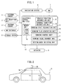
- FIG. 1 is a block diagram which shows the overall configuration of an automated driving system of a vehicle according to the present invention.
- this automated driving system of a vehicle comprises an external sensor 1 which detects information of surroundings of a host vehicle V, a GPS (global positioning system) reception unit 2, an internal sensor 3, a map database 4, a storage device 5, a navigation system 6, an HMI (human machine interface) 7, various actuators 8, and an electronic control unit (ECU) 10.
- the vehicle which is controlled by the automated driving system according to the present invention will be hereinafter referred to as "the host vehicle V" or simply “vehicle V".
- the external sensor 1 shows a detection device for detecting information on the surroundings of the host vehicle V, that is, the external conditions.
- This external sensor 1 includes at least one of a camera, radar, and LIDER (laser imaging detection and ranging device).
- the camera for example, as shown in FIG. 2 by the reference notation SA, is provided at a back side of a front windshield of the vehicle V.
- This camera SA captures an image of the front of the vehicle V.
- the captured information of this camera SA is sent to the electronic control unit 10.
- the radar is a device which utilizes radio waves to detect obstacles at the outside of the vehicle V. This radar detects obstacles around the vehicle V from the reflected waves of radio waves which are emitted from the radar to the surroundings of the vehicle V. Obstacle information which is detected by the radar is sent to the electronic control unit 10.
- the LIDER is a device which utilizes laser beams to detect the road on which the host vehicle V is running and outside obstacles.
- This LIDER for example, as shown in FIG. 2 by the reference notation SB, is installed on the roof of the vehicle V.
- this LIDER SB the distance to the road and obstacles around the road are measured from the reflected light of the laser beams which are successively fired toward the overall surroundings of the vehicle V, and the road and the presence of obstacles in the overall surroundings of the vehicle V are detected in the form of a three-dimensional image.
- the three-dimensional image of the road and obstacles which are detected by this LIDER SB are sent to the electronic control unit 10.
- the GPS reception unit 2 signals are received from three or more GPS satellites and thereby the absolute position of the host vehicle V (for example, the latitude and longitude of the vehicle V) is detected.
- the absolute position information of the vehicle V which is detected by the GPS reception unit 2 is sent to the electronic control unit 10.
- the internal sensor 3 shows a detection device for detecting the running state of the host vehicle V.
- This internal sensor 3 includes at least one of a vehicle speed sensor, acceleration sensor, and yaw rate sensor.
- the vehicle speed sensor is a detector which detects the speed of the vehicle V.
- the acceleration sensor for example, is a detector which detects an acceleration in a front-rear direction of the vehicle V.
- the yaw rate sensor is a detector which detects a rotational angular speed about a vertical axis of the center of gravity of the vehicle V. The information which is detected by the vehicle speed sensor, acceleration sensor, and yaw rate sensor are sent to the electronic control unit 10.
- the map database 4 shows a generally commercially available database relating to map information.
- This map database 4 is stored in, for example, an HDD (hard disk drive) which is mounted in the vehicle.
- the map information includes, for example, position information of the road, information of the road shape (for example, type such as curved or straight, curvature of curve, etc.), and position information of intersections and forks.
- the storage device 5 stores three-dimensional images of obstacles which were detected by the LIDER SB and road maps for the exclusive use of automated driving, which were prepared based on results of detection of the LIDER SB. These three-dimensional images of the obstacles and road maps are constantly or periodically updated. Note that, in the embodiment shown in FIG. 1 , the storage device 5 stores the three-dimensional images of obstacles when the vehicle is being driven at the exact center of a preselected driving lane.
- the navigation system 6 is a device which guides the driver of the vehicle V to a destination which is set by the driver.
- a target route to the destination is calculated based on the current position information of the host vehicle V which is measured by the GPS reception unit 2 and the map information of the map database 4. This information of the target route of the vehicle V is sent to the electronic control unit 10.
- the HMI 7 shows an interface for output and input of information between the driver of the vehicle V and the automated driving system of the vehicle V.
- This HMI 7 is provided with, for example, a display panel for displaying image information to the driver, a speaker for voice output, and operation buttons or a touch panel etc. for the driver to input instructions.
- a signal is sent to the electronic control unit 10 whereby the automated driving is started resulting in the automated driving mode where the vehicle is driven without operations of the driver.
- the automated driving mode is switched to the manual driving mode at this time as well.
- the actuator 8 is provided for performing the running control of the vehicle V.
- This actuator 8 includes at least an accelerator actuator, brake actuator, and steering wheel actuator.
- the accelerator actuator controls a throttle opening degree in accordance with a control signal from the electronic control unit 10 and thereby controls a drive force of the vehicle V.
- the brake actuator controls the amount of depression of a brake pedal in accordance with a control signal from the electronic control unit 10 and thereby controls a braking force given to the wheels of the vehicle V.
- the steering wheel actuator controls the drive of a steering assist motor of an electric power steering system in accordance with a control signal from the electronic control unit 10 and thereby controls a steering action of the vehicle V.
- the electronic control unit 10 comprises a CPU (central processing unit), ROM (read only memory), RAM (random access memory), etc which are connected to each other by a bidirectional bus.
- FIG. 1 shows the case of using a single electronic control unit 10, but a plurality of electronic control units can also be used.
- the electronic control unit 10 comprises a vehicle position recognition unit 11, external condition recognition unit 12, running state recognition unit 13, driving plan generation unit 14, running control unit 15, storage unit 16, driving scene judgment unit 17, and driving mode switching unit 18.
- the ROM and RAM configure the storage unit 16.
- the initial absolute position of the host vehicle V on the map of the map database 4 when automated driving is started is recognized at the vehicle position recognition unit 11 based on the position information of the host vehicle V which is received by the GPS reception unit 2.
- the position of the host vehicle V on the road in the map database 4 which is obtained using GPS is considerably off from the actual position of the host vehicle V on the road. Therefore, it is difficult to use the position of the host vehicle V which is obtained using GPS as the basis for automated driving.
- the road map for the exclusive use of automated driving which is stored in the storage device 5 is accurate, and the position of the host vehicle V on this road map for the exclusive use of automated driving which is stored at the storage device 5 substantially completely matches the actual position of the host vehicle V. Therefore, in the embodiment according to the present invention, the automated driving is performed based on the position of the host vehicle V on the road map for the exclusive use of automated driving which is stored at the storage device 5.
- the vehicle position recognition unit 11 if the initial absolute position of the host vehicle V when automated driving is started is recognized based on the position information of the host vehicle V which is received at the GPS reception unit 2, after that, the external conditions of the host vehicle V is recognized at the external condition recognition unit 12, and the accurate position of the host vehicle V on the road map for the exclusive use of automated driving which is stored at the storage device 5 is recognized based on this external conditions.
- the external condition recognition unit 12 the external conditions of the host vehicle V is recognized based on the results of detection by the external sensor 1 (for example, the captured information of the camera 8, the obstacle information from the radar, the three-dimensional images of the obstacles which are detected by the LIDER SB, etc.).
- the external conditions include the positions of white lines of a driving lane with respect to the vehicle V, the position of the center of the lane with respect to the vehicle V, the width of the road, the shape of the road (for example, the curvature of the driving lane, the change in grade of the road surface, etc.), and the situation of obstacles around the vehicle V (for example, information differentiating stationary obstacles and moving obstacles, positions of obstacles with respect to the vehicle V, the direction of movement of obstacles with respect to the vehicle V, the relative speed of obstacles with respect to the vehicle V, etc.).
- the initial absolute position of the host vehicle V when the automated driving is started is recognized based on position information of the host vehicle V which is received at the GPS reception unit 2
- the current accurate position of the host vehicle V on the road map which is stored in the storage device 5 is recognized by comparing the three-dimensional images of outside stationary obstacles which are stored in the storage device 5 based on the results of detection of the LIDER SB and the current three-dimensional images of outside stationary obstacles which detected by the LIDER SB at the external condition recognition unit 12.
- the three-dimensional images of outside stationary obstacles which are detected using the LIDER SB are shifted a little at a time to find the image position where these three-dimensional images are superposed over the three-dimensional images of the outside stationary obstacles which are stored in the storage device 5.
- the amount of shift of the three-dimensional images at this time expresses the amount of deviation of the vehicle V from the exact center of the driving lane on the road map which is stored in the storage device 5. Therefore, the current accurate position of the host vehicle V can be recognized based on this amount of deviation.
- the vehicle V is driven controlled so that the vehicle V runs at the exact center of the driving lane.
- the work of finding the image position where the three-dimensional images of outside stationary obstacles which are detected by the LIDER SB are superposed on the three-dimensional images of outside stationary obstacles which are stored in the storage device 5 is continuously performed during the time at which the vehicle V is driven, and the host vehicle V is driven controlled so that the vehicle V runs at the exact center of the driving lane of the target route which is set by the driver.
- this external condition recognition unit 12 by comparing the three-dimensional images of outside obstacles which are detected by the LIDER SB (stationary obstacles and moving obstacles) and the three-dimensional images of outside stationary obstacles which are stored in the storage device 5, the presence of moving obstacles such as pedestrians is recognized.
- the running state of the vehicle V is recognized based on the results of detection of the internal sensor 3 (for example, the vehicle speed information from the vehicle speed sensor, the acceleration information from the acceleration sensor, the rotational angular speed information of the yaw rate sensor, etc.).
- the running state of the vehicle V includes, for example, the vehicle speed, acceleration, and rotational angular speed about the vertical axis of the center of gravity of the vehicle V.
- the position of the vehicle V at the road map which is stored in the storage device 5 is recognized at the external condition recognition unit 12.
- a driving plan of the host vehicle V along the target route which is set by the driver is prepared based on the position of the vehicle which is recognized by the external condition recognition unit 12, the external conditions of the vehicle which are recognized by the external condition recognition unit 12 (position, advancing direction, etc. of other vehicle), and the speed of the vehicle V, acceleration, etc. which are detected by the internal sensor 3, that is, the running path of the host vehicle V is determined.
- the vehicle running path is determined so as to reach the destination safely and in the shortest time while observing the law.
- the driving scene of the vehicle is judged based on the information of the surroundings of the host vehicle V which is detected by the external sensor 1.
- the driving scenes which are covered by the judgment are set in advance, and, as preset driving scenes, there are a driving scene where the host vehicle V approaches another vehicle which is running in front of the host vehicle V and changes lanes to overtake the other vehicle and a driving scene where another vehicle which is running in front of the host vehicle V stops and the host vehicle V follows behind the other vehicle and stops. Which driving scene is corresponded to is judged from the motion of the host vehicle V and other vehicles.
- the driving mode of the vehicle V is switched to either the manual driving mode where the vehicle is driven by operations of the driver and the automated driving mode where the vehicle is driven without operations of the driver.
- the switching action of the driving mode is performed by the switching operation of the manual driving mode and the automated driving mode at the HMI 6 by the driver and a case where the switching action of the driving mode is performed by the switching operation from the automated driving mode to the manual driving mode based on the operation of the steering and the operation of the accelerator pedal by the driver.
- FIG. 3 and FIG. 4 show a three-dimensional space where an axis perpendicular to the xy plane is made the time axis "t".
- the xy plane of FIG. 3 represents the ground surface in the road map which is stored in the storage device 5, and in FIG. 3 , R indicates a road on the map which is stored at the storage device 5. Further, in FIG. 3 , V indicates a host vehicle which is driving on the road R, and the y-axis direction on the xy plane is made the advancing direction of the host vehicle V. Note that, the positions of the road R and the host vehicle V in FIG. 3 perfectly match the actual positions of the road R and the host vehicle V on a one-to-one basis.
- a trajectory of a future running path of the host vehicle V in the three-dimensional space comprised of the xyz axes is generated.
- the initial position of this trajectory is the current position of the host vehicle V.
- the position of the host vehicle V and the running state of the host vehicle V are made to change along with the advance of the vehicle V on the road map which is stored in the storage device 5.
- the acceleration of the vehicle is selected from a plurality of values which are preset in -10 to +30 km/h/sec in range, while the steering angular speed is selected from among a plurality of values which are preset in -7 to +7 degrees/sec in range.
- a plurality of the trajectories of the vehicle running paths are generated by connecting the positions (x, y) of the vehicle A which are found for the combinations of the plurality of values of acceleration and the plurality of values of steering angular speed of the vehicle V.
- "P" shows one representative trajectory among the thus obtained trajectories. If a plurality of the trajectories of the vehicle running paths are generated, for example a trajectory which is able to reach the destination safely and in the shortest time while observing the law is selected from among these trajectories, and this selected trajectory is determined as the advancing course of the host vehicle V. Note that, in FIG.
- the projection on the xy plane on the road R of this trajectory becomes the vehicle running path of the host vehicle V on the road R of the road map which is stored in the storage device 5.
- the running path of the vehicle V on the road map which is stored in the storage device 5 becomes the actual running path of the vehicle V on the actual road.
- FIG. 4 one example of the method of selecting a trajectory which is able to reach the destination safely and in the shortest time while observing the law from among these trajectories will be briefly explained.
- the xy plane of this FIG. 4 in the same way as in FIG. 3 , also represents the ground surface on the road map which is stored in the storage device 5.
- V in the same way as in FIG. 3 , shows the host vehicle, while A shows another vehicle in front of the host vehicle V which is advancing in the same direction as the vehicle V. Note that, in FIG. 4 , the plurality of the trajectories P of the vehicle running paths which are generated for the host vehicle V are shown.
- a plurality of the trajectories of the vehicle running paths for combinations of the plurality of values of acceleration of the vehicle and the plurality of values of steering angular speeds for the other vehicle A are generated as well.
- the plurality of the trajectories of the vehicle running paths which are generated for the other vehicle A are shown in FIG. 4 by P'.
- the driving plan generation unit 14 first, it is judged for all trajectories P, based on external information which is recognized by the external condition recognition unit 12, whether the host vehicle V can be driven on the road R and whether the host vehicle V will contact any fixed obstacle or pedestrian when the vehicle V is advancing according to a trajectory P. If it is judged that the vehicle V cannot be driven on the road R or if it is judged that the vehicle V will contact a fixed obstacle or pedestrian when the host vehicle V is advancing according to the trajectory P, that trajectory is excluded from the options and it is judged for the remaining trajectories P whether or not the host vehicle V interferes with the other vehicle A.
- the drive control of the engine of the vehicle V and control of the engine auxiliaries etc are performed at step 31
- the control for braking the vehicle V and control of the braking lights etc are performed at step 32
- the steering control and control of the direction lights etc are performed at step 33.
- These controls are updated each time acquiring an updated new driving plan at step 30. In this way, automated driving of the vehicle V along the generated driving plan is performed.
- FIG. 6A shows the road conditions, the vehicle speed "v" of the host vehicle V, and the required drive torque TR with respect to the vehicle V.
- the vehicle speed "v” shows one example of the vehicle speed based on the driving plan from the driving plan generation unit 14. The example which is shown in FIG.
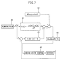
- the acceleration A(n) in the direction of advance of the vehicle V which should be applied to the vehicle V, is found from the vehicle speed "v" based on the driving plan generated by the driving plan generation unit 14, the required drive torque TR for the vehicle V is found from this acceleration A(n), and the drive operation of the engine is controlled so that the drive torque for the vehicle V becomes this required drive torque TR.
- the acceleration A(n) in the direction of advance of the vehicle at this time as shown in FIG.
- the drive operation of the engine is controlled so that the drive torque with respect to the vehicle V becomes this required drive torque TR.
- the engine load i.e, the opening degree of the throttle valve and the gear ratio of the transmission are controlled so that the drive torque with respect to the vehicle V becomes this required drive torque TR.
- the gear ratio of the transmission is determined in advance as a function of the vehicle speed "v" and the required drive torque TR, and accordingly, if the vehicle speed "v" and the required drive torque TR are determined, the target gear ratio of the transmission is determined.
- the target gear ratio of the transmission is determined, the engine speed and the engine output torque which give the vehicle speed "v" and the required drive torque TR are determined, and if the engine output torque is determined, the target opening degree of the throttle valve which gives this engine output torque is determined. In this way, the target gear ratio of the transmission and the target opening degree of the throttle valve are determined, and the gear ratio of the transmission and the opening degree of the throttle valve are controlled so as to become the target gear ratio of the transmission and the target opening degree of the throttle valve, respectively.
- acceleration A(0) obtained by the feed forward control unit 41 and acceleration AX obtained by the slope correction unit 43 are added, and in the calculation unit 44 of the required drive torque TR, the required drive torque TR for the vehicle V is calculated from the sum (A(0)+AX) of the acceleration A(0) obtained by the feed forward control unit 41 and the acceleration AX obtained by the slope correction unit 42.
- the actual vehicle speed vz is controlled to the vehicle speed v(n) which is generated based on the driving plan 40.
- a plurality of vehicle running paths are generated which show the changes along with time of the vehicle speed v and advancing direction ⁇ of the host vehicle V.
- a single vehicle running path which can reach the destination safely and in the shortest time while observing the law is selected from these plurality of vehicle running paths and the vehicle is automated driven along this selected vehicle running path.
- this selected vehicle running path will differ from the vehicle running path corresponding to the driving characteristics of the driver in many cases. If the selected vehicle running path differs from the vehicle running path corresponding to the driving characteristics of the driver, the driver is given an odd feeling. In this case, the driver feels odd in this way not when the vehicle is driving over a straight road at a constant speed, but when for example in a driving scene such as when overtaking another vehicle driving in the front.
- various driving scenes of the vehicle which may give an odd feeling to the driver are set in advance.
- the driving scene of the vehicle becomes a preset driving scene of the vehicle, generally speaking, a vehicle running path corresponding to the driving characteristics of the driver is selected as the vehicle running path.
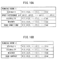
- the vehicle running path which is generated by the driving operations of the driver is learned.
- the vehicle running path which is generated by this driving operation of the driver is stored as a specific vehicle running path which represents the driving characteristics of the driver.
- the vehicle is driven along a vehicle running path close to the stored specific vehicle running path which represents the driving characteristics of the driver.
- the preset driving scene of the vehicle there are the case of approaching another vehicle which is running in front of the host vehicle and changing lanes to overtake the other vehicle, the case of another vehicle which is running in front of the host vehicle stopping and of following behind the other vehicle to stop, the case of approaching an obstacle present in front of the host vehicle and avoiding the obstacle, and various other driving scenes.
- the HMI 7 which is shown in FIG. 1
- the driver when the driver performs an input operation to stop the automated driving, a signal is sent to the electronic control unit 10 to stop the automated driving and the automated driving mode is switched to the manual driving mode. Note that, if, at the time of the automated driving mode, the driver turns the steering wheel or depresses the accelerator pedal, at this time as well, the automated driving mode is switched to the manual driving mode.
- FIG. 8A to FIG. 13B show one of the preset driving scene of the vehicle of approaching another vehicle which is running in front of the host vehicle and changing lanes to overtake the other vehicle as a representative driving scene.
- this driving scene will be called the "driving scene 1".
- R1 and R2 indicate two mutually adjoining driving lanes
- V shows the host vehicle which is driving on the driving lane R1
- A shows another vehicle which is running in front of the host vehicle V on the same driving lane R1 as the host vehicle V.
- DS and DE indicate distances from the other vehicle A. When the vehicle distance between the host vehicle V and the other vehicle A becomes smaller than the distance DS, it is judged that the driving scene is one of overtaking a vehicle.
- the solid line P which extends from the host vehicle V to the front shows the vehicle running path when the automated driving is not performed but the manual driving is continuously performed. That is, it shows the vehicle running path when the vehicle is being driven corresponding the driving characteristics of the driver.
- the host vehicle V changes lanes from the driving lane R1 to the driving lane R2.
- this lane change is a simple lane change and not a lane change for overtaking the other vehicle A in the front. That is, it is judged that the running state of the host vehicle V at this time does not correspond to a driving scene of overtaking a vehicle. Therefore, at this time, the vehicle running path P is not learned.
- the host vehicle V changes lanes from the driving lane R1 to the driving lane R2 when the vehicle distance between the host vehicle V and the other vehicle A is smaller than distance DS.
- this lane change is a lane change for overtaking another vehicle A at the front. That is, it is judged that the running state of the host vehicle V at this time corresponds to a driving scene of overtaking a vehicle.
- the host vehicle V changes lanes from the driving lane R1 to the driving lane R2 when the vehicle distance between the host vehicle V and the other vehicle A is smaller than the distance DE.
- This distance DE is set from the possibility of contact of the host vehicle V and the other vehicle A. If the host vehicle V changes lanes when the vehicle distance between the host vehicle V and the other vehicle A becomes smaller than the distance DE, it is judged that there is a possibility of contact of the host vehicle V and the other vehicle A.
- a vehicle running path where there is the possibility of contact of the host vehicle V and the other vehicle A in this way is unsuitable for driving the vehicle in accordance with this vehicle running path at the time of the automated driving mode even if representing the driving characteristics of the driver. Therefore, at this time, the vehicle running path P is not learned. That is, if the host vehicle V changes lanes when the vehicle distance between the host vehicle V and the other vehicle A is between the distance DE and the distance DS, it is judged that the driving scene is a driving scene of overtaking a vehicle and the vehicle running path P is learned.
- FIG. 9 shows the case where the host vehicle V changes lanes from the driving lane R1 to the driving lane R2 when the vehicle distance between the host vehicle V and the other vehicle A is between the distance DE and the distance DS, but after the host vehicle V changes lanes to the driving lane R2, the host vehicle V runs in the driving lane R2 leaning greatly to the left side or leaning greatly to the right side. In such a case, there is the possibility of the host vehicle V contacting the other vehicle, so the vehicle running path P is not learned.
- the driving scene is a driving scene of overtaking a vehicle and the vehicle running path P is learned in case where, as shown in FIG. 10A , the host vehicle V changes lanes when the vehicle distance between the host vehicle V and the other vehicle A is between the distance DE and the distance DS and, after the host vehicle V changes lanes to the driving lane R2, the host vehicle V is positioned in the driving lane R2 between the limit line HO and the limit line HI.
- the driving scene is a driving scene of overtaking a vehicle and the vehicle running path P is permitted to be learned when the vehicle distance between the host vehicle V and the other vehicle A at the time of the start of change of lanes of the host vehicle V is between the distance DE and the distance DS and the position of the host vehicle V in the driving lane R2 after the host vehicle V changes lanes to the driving lane R2 is between the limit line HO and the limit line HI.
- the distance between the distance DE and the distance DS is called the learning permission range
- the distance between the limit line HO and the limit line HI is called the learning permission range
- the vehicle distance between the host vehicle V and the other vehicle A at the time of the start of change of lanes of the vehicle V is within the learning permission range and the position of the host vehicle V in the driving lane R2 after the host vehicle V changes lanes to the driving lane R2 is in the learning permission range, it is judged that the driving scene is a driving scene of overtaking a vehicle and the vehicle running path P is learned.
- FIG. 10A shows when the vehicle distance between the host vehicle V and the other vehicle A at the time of the start of change of lanes of the host vehicle V is between the distance DE and the distance DS, that is, is within the learning permission range, and the position of the host vehicle V in the driving lane R2 after the host vehicle V changes lanes to the driving lane R2 is between the limit line HO and the limit line HI, that is, is within the learning permission range. Therefore, at this time, it is judged that the driving scene is a driving scene of overtaking a vehicle, and the vehicle running path P is learned.
- FIG. 10B shows one example of the learning method of the vehicle running path P at this time.
- the vehicle distance D(i) between the host vehicle V and the other vehicle A, the position (x(i), y(i)) of the host vehicle V, and the running state (v(i), ⁇ (i)) of the host vehicle V continue to be stored for each ⁇ t time.
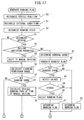
- the driving scene of the vehicle is continuously monitored by the driving scene judgment unit 17, based on the information of the surroundings of the vehicle which is detected by the external sensor 1.
- the driving scene judgment unit 17 when it is judged by the driving scene judgment unit 17 that the host vehicle V approaches another vehicle A which is running in front of the host vehicle V and changes lanes to overtake the other vehicle A and further at this time it is judged that the vehicle distance D(i) between the host vehicle V and the other vehicle A is shorter than the distance DS which is shown from FIG. 8A to FIG. 10B at the time of start of the lane change action, it is judged by the driving scene judgment unit 17 that the driving scene is a driving scene of overtaking a vehicle. Note that, in this case, for example, when the front end of the host vehicle V is positioned in the front from the front end of the other vehicle A, it is judged that the other vehicle A has been overtaken.
- the direction perpendicular to the advancing direction of the vehicle on the road map which is stored in the storage device 5 is made the x-coordinate
- the stored vehicle distance D(i) between the host vehicle V and the other vehicle A and the re-stored position (x(i), y(i)) of the vehicle V are used to judge whether the vehicle distance D(i) between the host vehicle V and the other vehicle A at the time of the start of change of lanes of the vehicle V is between the distance DE and the distance DS, that is, is within the learning permission range, and if the position of the host vehicle V in the driving lane R2 after the host vehicle V changes lanes to the driving lane R2 is between the limit line HO and the limit line HI, that is, is within the learning permission range.
- the stored vehicle distance D(i), position (x(i), y(i)) of the vehicle V, and running state (v(i), ⁇ (i)) of the vehicle V are erased.
- the vehicle running path P is not learned. That is, at this time, the vehicle running path P is not adopted as the specific vehicle running path which represents the driving characteristics of the driver when the driving scene is a driving scene of overtaking a vehicle.
- the vehicle running path P at this time is stored as the specific vehicle running path P which represents the driving characteristics of the driver at the time of a driving scene of overtaking a vehicle. That is, at this time, the vehicle running path P is learned, and the vehicle running path P is adopted as the specific vehicle running path which represents the driving characteristics of the driver when the driving scene is a driving scene of overtaking a vehicle.
- FIG. 11A and FIG. 11B show the vehicle running path when, at the time of the automated driving mode, the automated driving of the vehicle is performed by the automated driving system. Therefore, when the driving mode is set to the automated driving mode, the vehicle is automatically driven along this vehicle running path PO.
- this vehicle running path PO differs from the driving characteristics of the driver. In this case, sometimes the driver turns the steering wheel or depresses the accelerator pedal so that the vehicle running path becomes one corresponding to the driving characteristics of the driver.
- P shows the case where, at the time of the automated driving mode, the driver turns the steering wheel or depresses the accelerator pedal so that the vehicle running path becomes one corresponding to the driving characteristics of the driver and thereby the automated driving mode is switched to the manual driving mode.
- FIG. 11A shows the case where, judging from the driving characteristics of the driver, the timing of start of lane change of the host vehicle V would be too slow if using the vehicle running path PO by the automated driving system.
- the vehicle running path P sometimes the steering wheel is turned or the accelerator pedal is depressed to switch from the automated driving mode to the manual driving mode at an earlier timing compared with the time of the start of change of lanes of the host vehicle V by the automated driving.
- the vehicle running path P becomes the vehicle running path corresponding to the driving characteristics of the driver.
- FIG. 11A shows the case where, judging from the driving characteristics of the driver, the timing of start of lane change of the host vehicle V would be too slow if using the vehicle running path PO by the automated driving system.
- the vehicle running path P sometimes the steering wheel is turned or the accelerator pedal is depressed to switch from the automated driving mode to the manual driving mode at an earlier timing compared with the time of the start of change of lanes of the host vehicle V by the automated driving.
- the vehicle running path P becomes the vehicle running path
- 11B shows the case where, judging from the driving characteristics of the driver, the timing of start of lane change of the host vehicle V would be too early if using the vehicle running path PO by the automated driving system.
- the vehicle running path P sometimes the steering wheel is turned or the accelerator pedal is depressed to switch from the automated driving mode to the manual driving mode at a later timing compared with the time of the start of change of lanes of the host vehicle V by the automated driving.
- the vehicle running path P becomes the vehicle running path corresponding to the driving characteristics of the driver.
- the vehicle running path P is stored as the specific vehicle running path which represents the driving characteristics of the driver as shown in FIG. 10B .
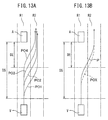
- FIG. 12A and FIG. 12B show the case of learning the vehicle running path P with the highest frequency among the plurality of vehicle running paths P along which the host vehicle V was driven when, for example, the driving scenes are ones of overtaking a vehicle at the time of the manual driving mode, the speeds of the host vehicle V are the same, the speeds of the other vehicle A are the same, and the weather and state of the road surface are the same.
- the vehicle running path P with the highest frequency of occurrence is found from the stored plurality of vehicle running paths P.
- the vehicle running paths P which are shown in FIG. 12B include the five vehicle running paths P1 to P5
- the sum of the squares of the differences of the values x(i) of the x-coordinates at different times between the vehicle running path P1 and the vehicle running path P2 and the squares of the differences of the values y(i) of the y-coordinates at the different times between the vehicle running path P1 and the vehicle running path P2 is calculated.
- the smaller this sum the closer the two vehicle running paths P.
- the above-mentioned sum is calculated for the vehicle running path P1 and the vehicle running path P3, next, the above-mentioned sum is calculated for the vehicle running path P1 and the vehicle running path P4, next, the above-mentioned sum is calculated for vehicle running path P1 and the vehicle running path P5 and finally the total of all of the above-mentioned sums is calculated.
- the above-mentioned sum for the vehicle running path P2 and the vehicle running path P1 the above-mentioned sum for the vehicle running path P2 and the vehicle running path P3, the above-mentioned sum for the vehicle running path P2 and the vehicle running path P4, and the above-mentioned sum for the vehicle running path P2 and the vehicle running path P5 are calculated, and then the total of all of the sums is calculated for the vehicle running path P2.
- the total of all of the sums is calculated for the vehicle running path P3, the total of all of the sums is calculated for the vehicle running path P4, and the total of all of the sums is calculated for the vehicle running path P5.
- the vehicle running path P with the smallest total of the sums among all of the totals of the sums which are calculated for these vehicle running paths P1, P2, P3, P4, and P5 is stored as the specific vehicle running path which represents the driving characteristics of the driver.
- FIG. 13A and FIG. 13B show the method of determination of the vehicle running path when it is judged that the driving scene is a driving scene of overtaking a vehicle at the time of the automated driving mode.
- a plurality of vehicle running paths which show changes along with time in the speed v and advancing direction 0 of the vehicle V are generated based on the information of the surroundings of the vehicle which is detected by the external sensor 1 and the map information.
- the plurality of vehicle running paths which are generated when it is judged that the driving scene is a driving scene of overtaking a vehicle at the time of the automated driving mode are shown in FIG. 13A by PO1, PO2, PO3, and PO4.
- a single vehicle running path which can reach the destination safely and in the shortest time while observing the law is selected from these plurality of vehicle running paths PO1, PO2, PO3, and PO4, and the vehicle is automatically driven along this selected vehicle running path POX.
- a single vehicle running path POX is determined from the plurality of vehicle running paths PO1, PO2, PO3, and PO4 by the driving plan generation unit 14, and the vehicle Is automatically driven along this determined vehicle running path POX.
- this selected vehicle running path POX will differ from the vehicle running path corresponding to the driving characteristics of the driver.
- the selected vehicle running path POX will give an odd feeling to the driver if the selected vehicle running path POX differs from the vehicle running path corresponding to the driving characteristics of the driver.
- a vehicle running path close to the specific vehicle running path which represents the driving characteristics of the driver is selected from among the plurality of vehicle running paths PO1, PO2, PO3, and PO4, and the vehicle V is automatically driven along this selected vehicle running path. That is, assuming that, in FIG. 13B , POX indicates a single vehicle running path which is determined by the driving plan generation unit 14 regardless of the driving characteristics of the driver, and, in FIG. 13B , P indicates a specific learned running path which represents the driving characteristics of the driver which are shown in FIG.
- a vehicle running path close to the specific vehicle running path P which represents the driving characteristics of the driver is selected from among the plurality of vehicle running paths PO1, PO2, PO3, and PO4 which are shown in FIG. 13A and the vehicle V is automatically driven along this selected vehicle running path.
- a vehicle running path close to the specific vehicle running path P which represents the driving characteristics of the driver is selected from among the plurality of vehicle running path PO1, PO2, PO3, and PO4.
- the vehicle running path closest to the specific vehicle running path P which represents the driving characteristics of the driver is selected from the plurality of vehicle running paths PO1, PO2, PO3, and PO4.
- the above-mentioned sum is calculated for the specific vehicle running path P shown in FIG. 13B and the vehicle running path PO2 shown in FIG. 13A
- the above-mentioned sum is calculated for the specific vehicle running path P shown in FIG. 13B and the vehicle running path PO3 shown in FIG. 13A
- the above-mentioned sum is calculated for the specific vehicle running path P shown in FIG. 13B and the vehicle running path PO4 shown in FIG. 13A
- the vehicle running path PO3 which becomes the smallest in the sums of the specific vehicle running path P and the vehicle running paths PO1, PO2, PO3, and PO4 is selected as the specific running path which represents the driving characteristics of the driver.
- the vehicle running path PO3 closest to the specific learned running path P expressing the driving characteristics of the driver is selected as the learned running path and the vehicle is automatically driven along this selected learned running path. Therefore, even if the vehicle V is automatically driven, the vehicle is driven corresponding to the driving characteristics of the driver. As a result, the driver is no longer given an odd feeling.
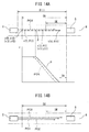
- FIG. 14A and FIG. 14B show a typical driving scene of one of the preset driving scenes of the vehicle where another vehicle which is running in front of the host vehicle V stops and the host vehicle V follows behind the other vehicle and stops.
- this driving scene will be referred to as the "driving scene 2".
- R shows a driving lane
- V shows the host vehicle which is driving on the driving lane R
- A shows another vehicle which is running in front of the host vehicle V on the same driving lane R as the host vehicle V.
- D(i), DS, DE, and DA show the distances from the other vehicle A to the host vehicle V.
- D(i) between the host vehicle V and the other vehicle A becomes smaller than the distance DS, it is judged that the driving scene is one for stopping the vehicle.
- DA shows the vehicle distance between the host vehicle V and the other vehicle A when the host vehicle V is stopped.
- the solid line P which extends from the host vehicle V forward shows the vehicle running path when the automated driving is not performed but when the manual driving is continuously performed or when the driver operates the brake pedal and the automated driving mode is switched to the manual driving mode. That is, the solid line P shows the vehicle running path when the vehicle is made to be driven corresponding to the driving characteristics of the driver.
- the change in the speed v of the vehicle when, at the time of the manual driving mode, the driving scene becomes a driving scene for stopping the vehicle is shown by the solid line P.
- this stopping action is a simple stopping action and not a driving scene where the other vehicle A which is running in front of the host vehicle V is stopped and where the host vehicle V follows behind the other vehicle A and stops. That is, it is judged that the stopping action of the host vehicle V at this time does not correspond to a driving scene where the other vehicle A which is running in front of the host vehicle V is stopped and where the host vehicle V follows behind the other vehicle A and stops. Therefore, at this time, the vehicle running path P is not learned.
- the stopping action of the vehicle V is performed when the vehicle distance D(i) between the host vehicle V and the other vehicle A is smaller than the distance DS, it is judged that the driving scene is a driving scene where the other vehicle A which is running in front of the host vehicle V is stopped and where the host vehicle V follows behind the other vehicle A and stops.
- the stopping action of the host vehicle V is performed when the vehicle distance D(i) between the host vehicle V and the other vehicle A is smaller than the distance DE, it is judged that the driving scene is one where the other vehicle A which is running in front of the host vehicle V is stopped and where the host vehicle V follows behind the other vehicle A and stops.
- this distance DE is determined from the possibility of contact between the host vehicle V and the other vehicle A when the stopping action of the host vehicle V is performed. If the vehicle distance D(i) between the host vehicle V and the other vehicle A becomes smaller than the distance DE, if the host vehicle V stopping action is performed, it is judged that there is the possibility of contact between the host vehicle V and the other vehicle A. Therefore, at this time, the vehicle running path P is not learned.
- the stopping action of the host vehicle V is performed when the vehicle distance between the host vehicle V and the other vehicle A is between the distance DE and the distance DS, it is judged that the driving scene is the driving scene for the host vehicle V to follow behind the other vehicle A and stop and the vehicle running path P is learned.
- the distance between the distance DE and the distance DS is called the "learning permission range”. Therefore, in the present invention, when the vehicle distance D(i) between the host vehicle V and the other vehicle A at the time of start of the stopping action of the host vehicle V is within the learning permission range, it is judged that the driving scene is a driving scene for the host vehicle V to follow behind the other vehicle A and stop and the vehicle running path P is learned.
- FIG. 14A shows the case where the vehicle distance between the host vehicle V and the other vehicle A at the time of starting the stopping action of the host vehicle V is between the distance DE and the distance DS, that is, is within the learning permission range. Therefore, at this time, it is judged that the driving scene is a driving scene for the host vehicle V to follow behind the other vehicle A and stop, and the vehicle running path P is learned.
- FIG. 14A one example of the learning method of the vehicle running path P which is performed at this time is shown.
- the vehicle distance D(i) between the host vehicle V and the other vehicle A, the position (x(i), y (i)) of the host vehicle V, and the running state (v(i), ⁇ (i)) of the host vehicle V for each ⁇ t time continue to be stored.
- the driving scene of the vehicle is constantly monitored by the driving scene judgment unit 17 based on the information of the surroundings of the vehicle which is detected by the external sensor 1.
- the driving scene judgment unit 17 when it is judged by the driving scene judgment unit 17 that the host vehicle V follows behind the other vehicle A and stops and at this time the vehicle distance D(i) between the host vehicle V and the other vehicle A at the time of start of the stopping action of the host vehicle V is shorter than the distance DS shown in FIG. 14A , it is judged by the driving scene judgment unit 17 that the driving scene is a driving scene where the host vehicle V follows behind the other vehicle A and stops.
- the direction perpendicular to the advancing direction of the vehicle on the road map which is stored in the storage device 5 is made the x-coordinate.
- the vehicle distance D(i) between the host vehicle V and the other vehicle A becomes the distance DA which is shown in FIG.
- the stored vehicle distance D(i) between the host vehicle V and the other vehicle A and the re-stored position (x(i), y(i)) of the vehicle V are used to judge whether the vehicle distance D(i) between the host vehicle V and the other vehicle A at the time of starting the stopping action of the host vehicle V is between the distance DE and the distance DS, that is, is within the learning permission range.
- the stored vehicle distance D(i), the position (x(i), y(i)) of the vehicle V, and the running state (v(i), ⁇ (i)) of the vehicle V are erased.
- the vehicle running path P is not learned. That is, at this time, the vehicle running path P is not adopted as the specific vehicle running path which represents the driving characteristics of the driver at the time of a driving scene where the vehicle V follows behind another vehicle A and stops.
- the vehicle running path at this time is stored as the specific vehicle running path P which represents the driving characteristics of the driver at the time of the driving scene for the host vehicle V to follow behind the other vehicle A and stop. That is, at this time, the vehicle running path is learned and the vehicle running path P is adopted as a specific vehicle running path which represents the driving characteristics of the driver at the time of the driving scene for the host vehicle V to follow behind the other vehicle A and stop.
- FIG. 14B shows the method of determination of the vehicle running path when it is judged at the time of the automated driving mode that the driving scene is a driving scene for the host vehicle V to follow behind the other vehicle A and stop. That is, as explained above, in the present invention, a plurality of vehicle running paths which show the changes along with time of the speed v and advancing direction ⁇ of the host vehicle V are generated based on the information on the surroundings of the vehicle which is detected by the external sensor 1 and the map information.
- the plurality of vehicle running paths which are generated at the time of the automated driving mode when it is judged that the driving scene is one for the host vehicle V to follow behind another vehicle A and stop are shown in FIG. 14B by PO1, PO2, and PO3.
- a single vehicle running path POX which can reach the destination safely and in the shortest time while observing the law is selected from the plurality of vehicle running paths PO1, PO2, and PO3, and the vehicle is automatically driven along this selected vehicle running path POX.
- a single vehicle running path POX is determined from the plurality of vehicle running paths PO1, PO2, and PO3 by the driving plan generation unit 14 and the vehicle is automatically driven along this determined vehicle running path POX.
- the vehicle running path POX and vehicle speed v at this time are shown in FIG. 14A by the broken lines.
- this selected vehicle running path POX will often differ from the vehicle running path corresponding to the driving characteristics of the driver. If the selected vehicle running path POX differs from the vehicle running path corresponding to the driving characteristics of the driver, the driver is given an odd feeling.
- the vehicle running path close to the specific vehicle running path P which represents the driving characteristics of the driver is selected from the plurality of vehicle running paths PO1, PO2, and PO3 and the vehicle V is automatically driven along the selected vehicle running path. That is, in FIG. 14A , if assuming "P" indicates a specific vehicle running path expressing operating characteristics of the driver, in the present invention, in FIG.
- a vehicle running path close to the specific vehicle running path P which represents the driving characteristics of the driver is selected from the plurality of vehicle running paths PO1, PO2, and PO3 which are shown in FIG. 14B and the vehicle V is automatically driven along this selected vehicle running path.
- the vehicle running path closest to the specific vehicle running path P which represents the driving characteristics of the driver is selected from the plurality of vehicle running paths PO1, PO2, and PO3 will be explained.
- the above-mentioned sum is calculated for the specific vehicle running path P shown in FIG. 14A and the vehicle running path P02 shown in FIG. 14B
- next the above-mentioned sum is calculated for the specific vehicle running path P shown in FIG. 14A and the vehicle running path P03 shown in FIG. 14B
- the vehicle running path PO2 which becomes the smallest among the sums for the vehicle running path P and the vehicle running paths PO1, PO2, and PO3 is selected as the specific learned running path which represents the driving characteristics of the driver.
- the vehicle running path PO2 closest to the specific vehicle running path P which represents the driving characteristics of the driver is selected as the specific vehicle running path and the vehicle is automatically driven along this selected vehicle running path. Therefore, even if the vehicle V is automatically driven, the vehicle is driven corresponding to the driving characteristics of the driver and, as a result, the driver is no longer given an odd feeling.
- an external sensor 1 which detects information of surroundings of a host vehicle V
- a storage device 5 which stores map information
- an electronic control unit 10 which controls the operation of the configuration of the automated driving system of FIG. 15A .
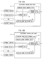
- the electronic control unit 10 comprises a driving plan generation unit 14 which generates a plurality of vehicle running paths which show changes along with time of a speed and advancing direction of the host vehicle V based on the map information stored in the storage device 5 and the information of surroundings of the host vehicle V which is detected by the external sensor 1 and decides on a single vehicle running path from among these plurality of vehicle running paths, a driving scene judgment unit 17 which judges a driving scene of the host vehicle V based on the information of the surroundings of the host vehicle V which is detected by the external sensor 1, a driving mode switching unit 18 which switches a driving mode of the host vehicle V between a manual driving mode where the vehicle is driven by operations of the driver and an automated driving mode where the vehicle is driven without operations of the driver, and a storage unit 16 which stores a running path of the host vehicle V in a preset driving scene at the time of the manual driving mode as a specific vehicle running path which represents the driving characteristics of the driver in the preset driving scene.
- the driving plan generation unit 14 selects a vehicle running path from the plurality of vehicle running paths when the driving scene becomes a driving scene for which the specific vehicle running path is stored in such a way that the selected vehicle running path is closer to the specific vehicle running path compared with the single vehicle running path which is determined by the driving plan generation unit 14 regardless of the driving characteristics of the driver, that is, compared with the single vehicle running path which is determined by the driving plan generation unit 14 when no specific vehicle running path is stored, and the driving plan generation unit 14 makes the vehicle be automated driven along with the selected vehicle running path.
- the above-mentioned preset driving scene is a driving scene where the host vehicle V approaches another vehicle A running in front of the host vehicle V and changes lanes and overtakes the other vehicle A. Further, in the embodiment according to the present invention, the above-mentioned preset driving scene is a driving scene where another vehicle A running in front of the host vehicle V stops and the host vehicle V follows behind the other vehicle A and stops.
- a learning permission judgment unit 19 which judges at the time of the manual driving mode whether the running path of the vehicle V falls within a learning permission range which is predetermined in accordance with the driving scene.
- the learning permission judgment unit 19 judges at the time of the manual driving mode whether the running path of the vehicle V falls within a learning permission range which is predetermined in accordance with the driving scene.
- the learning permission range is the range for the vehicle distance between the host vehicle V and the other vehicle A at the time of the start of change of lanes of the host vehicle V
- the learning permission range is the range for the vehicle distance between the host vehicle V and the other vehicle A when the vehicle stopping action of the host vehicle V is started.
- the vehicle running path P is learned.
- the learning permission range changes depending on the speed of the host vehicle V, the speed difference ⁇ V between the host vehicle V and another vehicle A, the extent of visibility, the weather, and the conditions of the road surface.
- the vehicle distance DS and the vehicle distance DE between the host vehicle V and the other vehicle A at the time of the start of change of lanes of the host vehicle V are made longer the higher the speed of the host vehicle V, are made longer the larger the speed difference ⁇ V between the host vehicle V and another vehicle A, are made longer the poorer the visibility, are made longer the poorer the weather, and are made longer the more slippery the road surface.
- coefficient values V(i), ⁇ V(i), F(i), C(i), and R(i) are preset as shown in FIG. 16A and are stored in the ROM of the electronic control unit 10. In this case, the coefficient values V(i), ⁇ V(i), F(i), C(i), and R(i) become larger step by step in small amounts from the left side to the right side in FIG. 16A .
- the higher the speed of the vehicle V the larger the speed difference ⁇ V between the host vehicle V and another vehicle A, the poorer the visibility, the poorer the weather, and the more slippery the road surface, the more to the right side the position of the coefficient value in FIG. 16A used.
- FIG. 16A shows the coefficient values V(i), ⁇ V(i), F(i), C(i), and R(i) in the case where the driving scene is the driving scene 1 of overtaking the vehicle.
- the vehicle running path P is learned when the vehicle distance between the host vehicle V and the other vehicle A at the time of start of the stopping action of the host vehicle V is between the distance DE and the distance DS, that is, is within the learning permission range.
- this learning permission range changes depending on the speed of the host vehicle V, the extent of visibility, the weather, and the conditions of the road surface.
- the vehicle distance DS and vehicle distance DE between the host vehicle V and the other vehicle A at the time of start of the stopping action of the host vehicle V are made longer the higher the speed of the vehicle V, are made longer the poorer the visibility, are made longer the poorer the weather, and are made longer the more slippery the road surface.
- coefficient values V(i), F(i), C(i), and R(i) are preset as shown in FIG. 16B and are stored in the ROM of the electronic control unit 10. In this case, the coefficient values V(i), F(i), C(i), and R(i) become larger in FIG. 16B from the left side toward the right side a little at a time. The higher the speed of the vehicle V, the poorer of the visibility, the poorer the weather, and the more slippery the road surface, the more to the right side in FIG. 16B the position of the coefficient value used. Note that, FIG. 16B shows the coefficient values V(i), F(i), C(i), and R(i) in the case where the driving scene is the driving scene 2 for following behind another vehicle A then stopping.
- the external sensor 1 is provided with sensors for detecting the extent of visibility, the weather, and the conditions of the road surface.
- FIG. 17 and FIG. 18A and FIG. 18B show the routine for generating a driving plan for working the present invention. This routine for generation of a driving plan is repeatedly executed.
- step 50 the position of the host vehicle V is recognized by the vehicle position recognition unit 11 based on the position information of the host vehicle V which is received at the GPS reception unit 2.
- step 51 the external conditions of the host vehicle V and the accurate position of the host vehicle V are recognized by the external condition recognition unit 12 based on the results of detection of the external sensor 1.
- step 52 the running state of the host vehicle V is recognized by the running state recognition unit 13 based on the results of detection of the internal sensor 3.
- step 53 it is judged whether the driving mode is the automated driving mode, that is, whether automated driving is being performed.
- the routine proceeds to step 56.
- step 54 it is judged whether the steering wheel has been turned or the accelerator pedal has been depressed during the automated driving and thereby a request for switching operation from the automated driving mode to the manual driving mode has been issued.
- step 55 the automated driving mode is switched to the manual driving mode.
- step 56 the routine proceeds to step 56. Therefore, the routine proceeds to step 56 at the time of the manual driving mode, that is, when manual driving is being performed.
- the learning permission range corresponding to the speed of the host vehicle V, the speed difference ⁇ V between the host vehicle V and another vehicle A, the extent of visibility, the weather, and the state of the road surface at the different driving scenes is calculated.
- the vehicle distance DS and vehicle distance DE between the host vehicle V and the other vehicle A at the time of the start of change of lanes of the host vehicle V are calculated based on FIG. 16A . That is, the vehicle distance DS is calculated by multiplying the reference vehicle distance DSO with the coefficient values V(i), ⁇ V(i), F(i), C(i), and R(i) which are shown in FIG.
- step 57 the vehicle distance DS which was calculated at step 56 is used as the basis to judge which of the preset driving scenes the driving scene is.
- the processing cycle is ended.
- the routine proceeds to step 58 where the vehicle running path is found.
- step 59 of FIG. 18A it is judged whether the vehicle running path at the time of this manual driving mode falls within the learning permission range at the corresponding driving scene.
- the data which shows the position (x(i), y(i)) of the vehicle V and the running state (v(i), ⁇ (i)) of the vehicle V is erased.
- the routine proceeds to step 60 of FIG.
- step 54 when at step 54 it is judged that no request for switching operation from the automated driving mode to the manual driving mode is issued, that is, at the time of the automated driving, the routine proceeds to step 61 where the information on the surroundings of the vehicle which is obtained from the results of detection of the external sensor 1 is used as the basis to judge what kind of driving scene the driving scene of the vehicle is, then what kind of driving scene the driving scene of the vehicle is is determined.
- step 62 the plurality of vehicle running paths PO1, PO2, PO3, and PO4 which show the change along with time of the speed v and advancing direction ⁇ of the vehicle V such as shown in FIG. 13A or FIG. 14B are generated.
- step 63 it is judged whether the driving scene which was determined at step 61 is any of the preset driving scenes.
- the routine proceeds to step 68 where a single vehicle running path which can reach the destination safely and in the shortest time while observing the law is selected from the plurality of vehicle running paths PO1, PO2, PO3, and PO4.In this case, the vehicle V is automatically driven along this selected vehicle running path.
- step 64 the routine proceeds to step 64 where the current speed of the vehicle V, the current speed difference ⁇ V between the host vehicle V and another vehicle A, the current extent of visibility, the current weather, and the current conditions of the road surface are detected and for example the coefficient values V(i), ⁇ V(i), F(i), C(i), and R(i) for the learning permission range according to the current speed of the vehicle V, the current speed difference ⁇ between the host vehicle V and another vehicle A, the current extent of visibility, the current weather, and the current conditions of the road surface are found.
- step 65 it is judged for the driving scene which was determined at step 61 whether the vehicle running path P in the manual driving at the current speed of the vehicle V, the current speed difference ⁇ V between the host vehicle V and another vehicle A, the current extent of visibility, the current weather, and the current conditions of the road surface is stored as the specific vehicle running path which represents the driving characteristics of the driver, for example, whether the vehicle running path P at the time of manual driving when the coefficient values for the learning permission range are V(i), ⁇ V(i), F(i), C(i), and R(i) is stored as the specific vehicle running path which represents the driving characteristics of the driver.
- the routine proceeds to step 68 where a single vehicle running path which can reach the destination safely and in the shortest time while observing the law is selected from the plurality of vehicle running paths PO1, PO2, PO3, and PO4.In this case, the vehicle V is automatically driven along this selected vehicle running path.
- step 65 when it is judged for the driving scene which was determined at step 61 that the vehicle running path P in the manual driving at the current speed of the vehicle V, the current speed difference ⁇ V between the host vehicle V and another vehicle A, the current extent of visibility, the current weather, and the current conditions of the road surface is stored as the specific vehicle running path which represents the driving characteristics of the driver, for example, when it is judged that the vehicle running path P at the time of manual driving when the coefficient values for the learning permission range are V(i), ⁇ V(i), F(i), C(i), and R(i) is stored as the specific vehicle running path which represents the driving characteristics of the driver, the routine proceeds to step 66 where for example the vehicle running path closest to the stored specific running path P is selected from the plurality of vehicle running paths PO1, PO2, PO3, and PO4 which were generated at step 62. Next, at step 67, this selected vehicle running path is determined as the specific vehicle running path which represents the driving characteristics of the driver, then the vehicle V is automatically driven along the determined specific vehicle running path which represents the
- FIG. 18B shows a modification of the part of the routine which is shown in FIG. 18A .
- step 59 when it is judged that the vehicle driving operation at the time of manual driving mode is not within the learning permission range, data which shows the position (x(i), y(i)) of the vehicle V and the running state (v(i), ⁇ (i)) of the vehicle V is erased.
- step 60a when at step 59 it is judged that the vehicle driving operation at the time of the manual driving mode is within the learning permission range, the routine proceeds to step 60a where, in the manner as explained with reference to FIG.
- the vehicle running path P with the highest frequency of occurrence is calculated from the plurality of vehicle running paths at the time of the manual driving mode.
- the learned running path P with the highest frequency of occurrence is selected as the specific vehicle running path which represents the driving characteristics of the driver when the values of the coefficients for the learning permission range are V(i), ⁇ V(i), F(i), C(i), R(i), and data which shows the position (x(i), y(i)) of the vehicle V and the running state (v(i), ⁇ (i)) of the vehicle V of the vehicle running path P with the highest frequency of occurrence is stored.
Landscapes
- Engineering & Computer Science (AREA)
- Automation & Control Theory (AREA)
- Transportation (AREA)
- Mechanical Engineering (AREA)
- Human Computer Interaction (AREA)
- General Physics & Mathematics (AREA)
- Physics & Mathematics (AREA)
- Combustion & Propulsion (AREA)
- Chemical & Material Sciences (AREA)
- Aviation & Aerospace Engineering (AREA)
- Radar, Positioning & Navigation (AREA)
- Remote Sensing (AREA)
- Atmospheric Sciences (AREA)
- Life Sciences & Earth Sciences (AREA)
- Control Of Driving Devices And Active Controlling Of Vehicle (AREA)
- Traffic Control Systems (AREA)
- Controls For Constant Speed Travelling (AREA)
- Business, Economics & Management (AREA)
- Health & Medical Sciences (AREA)
- Artificial Intelligence (AREA)
- Evolutionary Computation (AREA)
- Game Theory and Decision Science (AREA)
- Medical Informatics (AREA)
Applications Claiming Priority (1)
| Application Number | Priority Date | Filing Date | Title |
|---|---|---|---|
| JP2015135313A JP6376059B2 (ja) | 2015-07-06 | 2015-07-06 | 自動運転車両の制御装置 |
Publications (2)
| Publication Number | Publication Date |
|---|---|
| EP3115272A1 true EP3115272A1 (fr) | 2017-01-11 |
| EP3115272B1 EP3115272B1 (fr) | 2017-11-29 |
Family
ID=56368872
Family Applications (1)
| Application Number | Title | Priority Date | Filing Date |
|---|---|---|---|
| EP16178078.8A Active EP3115272B1 (fr) | 2015-07-06 | 2016-07-06 | Système de commande de conduite de véhicule automatisée |
Country Status (4)
| Country | Link |
|---|---|
| US (1) | US9914458B2 (fr) |
| EP (1) | EP3115272B1 (fr) |
| JP (1) | JP6376059B2 (fr) |
| CN (1) | CN106338988B (fr) |
Cited By (6)
| Publication number | Priority date | Publication date | Assignee | Title |
|---|---|---|---|---|
| GB2555397A (en) * | 2016-10-24 | 2018-05-02 | Bae Systems Plc | Control of automonous vehicles |
| EP3418162A1 (fr) * | 2017-06-19 | 2018-12-26 | Aptiv Technologies Limited | Système de maintien de voie pour véhicule automatisé |
| WO2019158261A1 (fr) * | 2018-02-15 | 2019-08-22 | Jaguar Land Rover Limited | Système et procédé de commande de véhicule |
| EP3627470A4 (fr) * | 2017-05-16 | 2020-05-27 | Nissan Motor Co., Ltd. | Procédé de prédiction de mouvement pour dispositif d'aide au déplacement et dispositif de prédiction de mouvement |
| EP3582056A4 (fr) * | 2017-09-05 | 2020-11-04 | Baidu Online Network Technology (Beijing) Co., Ltd | Procédé et dispositif d'apprentissage de données pour véhicule autonome |
| US11281213B2 (en) | 2016-10-24 | 2022-03-22 | Bae Systems Plc | Control of autonomous vehicles |
Families Citing this family (102)
| Publication number | Priority date | Publication date | Assignee | Title |
|---|---|---|---|---|
| US9616773B2 (en) | 2015-05-11 | 2017-04-11 | Uber Technologies, Inc. | Detecting objects within a vehicle in connection with a service |
| JP6565615B2 (ja) * | 2015-11-06 | 2019-08-28 | 株式会社デンソー | 車両制御装置 |
| JP6524892B2 (ja) * | 2015-11-13 | 2019-06-05 | 株式会社デンソー | 車両の走行路情報生成システム |
| US10712160B2 (en) | 2015-12-10 | 2020-07-14 | Uatc, Llc | Vehicle traction map for autonomous vehicles |
| US9840256B1 (en) | 2015-12-16 | 2017-12-12 | Uber Technologies, Inc. | Predictive sensor array configuration system for an autonomous vehicle |
| US9841763B1 (en) | 2015-12-16 | 2017-12-12 | Uber Technologies, Inc. | Predictive sensor array configuration system for an autonomous vehicle |
| JP6327244B2 (ja) * | 2015-12-25 | 2018-05-23 | トヨタ自動車株式会社 | 車両制御装置 |
| US9990548B2 (en) | 2016-03-09 | 2018-06-05 | Uber Technologies, Inc. | Traffic signal analysis system |
| US20170329331A1 (en) * | 2016-05-16 | 2017-11-16 | Magna Electronics Inc. | Control system for semi-autonomous control of vehicle along learned route |
| JP6387369B2 (ja) * | 2016-05-23 | 2018-09-05 | 本田技研工業株式会社 | 走行制御装置 |
| CN106114507B (zh) * | 2016-06-21 | 2018-04-03 | 百度在线网络技术(北京)有限公司 | 用于智能车辆的局部轨迹规划方法和装置 |
| US10739786B2 (en) | 2016-07-01 | 2020-08-11 | Uatc, Llc | System and method for managing submaps for controlling autonomous vehicles |
| US10162354B2 (en) * | 2016-07-21 | 2018-12-25 | Baidu Usa Llc | Controlling error corrected planning methods for operating autonomous vehicles |
| US11273826B2 (en) * | 2017-01-23 | 2022-03-15 | Honda Motor Co., Ltd. | Vehicle control system, vehicle control method, and storage medium |
| JP6676196B2 (ja) * | 2017-01-24 | 2020-04-08 | 本田技研工業株式会社 | 車両制御システム、車両制御方法、および車両制御プログラム |
| JP2020508252A (ja) * | 2017-02-10 | 2020-03-19 | ニッサン ノース アメリカ,インク | 自律走行車の動作管理 |
| WO2018154995A1 (fr) * | 2017-02-22 | 2018-08-30 | ジヤトコ株式会社 | Dispositif et procédé de commande de véhicule |
| WO2018157386A1 (fr) * | 2017-03-03 | 2018-09-07 | Baidu.Com Times Technology (Beijing) Co., Ltd. | Préréglage de moyen de commande en cascade de longitude pour commander un véhicule à conduite autonome repassant en mode de conduite autonome |
| JP6445062B2 (ja) * | 2017-03-08 | 2018-12-26 | ヤマハモーターパワープロダクツ株式会社 | 自動運転車両 |
| JP6690581B2 (ja) * | 2017-03-09 | 2020-04-28 | オムロン株式会社 | 運転モード切替制御装置、方法およびプログラム |
| KR102262579B1 (ko) * | 2017-03-14 | 2021-06-09 | 현대자동차주식회사 | 차선 변경 장치, 그를 포함하는 시스템, 및 그 방법 |
| US10518770B2 (en) * | 2017-03-14 | 2019-12-31 | Uatc, Llc | Hierarchical motion planning for autonomous vehicles |
| CN110462544A (zh) * | 2017-03-20 | 2019-11-15 | 御眼视觉技术有限公司 | 自主车辆的轨迹选择 |
| JP6572930B2 (ja) * | 2017-03-24 | 2019-09-11 | 株式会社デンソー | 情報処理装置及び情報処理システム |
| JP6940969B2 (ja) * | 2017-03-29 | 2021-09-29 | パナソニック インテレクチュアル プロパティ コーポレーション オブ アメリカPanasonic Intellectual Property Corporation of America | 車両制御装置、車両制御方法及びプログラム |
| US20200051436A1 (en) * | 2017-03-30 | 2020-02-13 | Honda Motor Co., Ltd. | Vehicle control apparatus and vehicle control method |
| US20180292836A1 (en) * | 2017-04-06 | 2018-10-11 | Delphi Technologies, Inc. | Automated vehicle operation-rules selected based on automation-level other vehicles |
| JP6558393B2 (ja) * | 2017-04-06 | 2019-08-14 | トヨタ自動車株式会社 | 進路設定装置及び進路設定方法 |
| US11731665B2 (en) * | 2017-04-12 | 2023-08-22 | Nissan Motor Co., Ltd. | Driving control method and driving control device |
| US10838422B2 (en) * | 2017-04-13 | 2020-11-17 | Panasonic Intellectual Property Corporation Of America | Information processing method and information processing apparatus |
| US20180307228A1 (en) * | 2017-04-20 | 2018-10-25 | GM Global Technology Operations LLC | Adaptive Autonomous Vehicle Driving Style |
| JP6587650B2 (ja) * | 2017-04-28 | 2019-10-09 | 矢崎総業株式会社 | 自動運転時情報伝達方法および車載情報提示装置 |
| US10816973B2 (en) * | 2017-06-02 | 2020-10-27 | Baidu Usa Llc | Utilizing rule-based and model-based decision systems for autonomous driving control |
| US10444759B2 (en) * | 2017-06-14 | 2019-10-15 | Zoox, Inc. | Voxel based ground plane estimation and object segmentation |
| US20180374341A1 (en) * | 2017-06-27 | 2018-12-27 | GM Global Technology Operations LLC | Systems and methods for predicting traffic patterns in an autonomous vehicle |
| KR102013590B1 (ko) | 2017-07-18 | 2019-08-23 | 엘지전자 주식회사 | 차량에 구비된 차량 제어 장치 및 차량의 제어방법 |
| US10466706B2 (en) * | 2017-08-14 | 2019-11-05 | Aptiv Technologies Limited | Automated guidance system |
| US10678263B2 (en) * | 2017-08-18 | 2020-06-09 | GM Global Technology Operations LLC | Method and apparatus for position error detection |
| JP6984232B2 (ja) * | 2017-08-25 | 2021-12-17 | トヨタ自動車株式会社 | 自動運転装置 |
| JP6946861B2 (ja) * | 2017-08-29 | 2021-10-13 | トヨタ自動車株式会社 | 自動運転評価装置及び自動運転評価方法 |
| WO2019044427A1 (fr) | 2017-08-31 | 2019-03-07 | パナソニックIpマネジメント株式会社 | Procédé d'aide, et système d'aide et dispositif d'aide faisant appel audit procédé |
| CN107564363B (zh) * | 2017-09-05 | 2019-11-05 | 百度在线网络技术(北京)有限公司 | 一种用于驾驶模式切换的方法和装置 |
| CN107745711B (zh) * | 2017-09-05 | 2021-01-05 | 百度在线网络技术(北京)有限公司 | 一种在自动驾驶模式下确定路线的方法和装置 |
| US10860019B2 (en) | 2017-09-08 | 2020-12-08 | Motional Ad Llc | Planning autonomous motion |
| US12276983B2 (en) | 2017-09-08 | 2025-04-15 | Motional Ad Llc | Planning autonomous motion |
| JP6568559B2 (ja) * | 2017-09-13 | 2019-08-28 | 株式会社Subaru | 車両の走行制御装置 |
| US11003183B2 (en) * | 2017-09-13 | 2021-05-11 | Baidu Usa Llc | Driving scene based path planning for autonomous driving vehicles |
| KR102064222B1 (ko) * | 2017-09-22 | 2020-03-02 | 엘지전자 주식회사 | 차량의 운행 시스템을 제어하는 방법 |
| JP6652539B2 (ja) * | 2017-10-12 | 2020-02-26 | 矢崎総業株式会社 | 自動運転時情報伝達方法および車載情報提示装置 |
| EP3476681B1 (fr) * | 2017-10-26 | 2024-12-04 | Ningbo Geely Automobile Research & Development Co. Ltd. | Véhicule à entraînement autonome |
| JP6580107B2 (ja) | 2017-11-02 | 2019-09-25 | 本田技研工業株式会社 | 車両制御装置 |
| JP6660929B2 (ja) * | 2017-12-04 | 2020-03-11 | 本田技研工業株式会社 | 車両の制御装置 |
| US11197405B2 (en) * | 2017-12-07 | 2021-12-14 | Kubota Corporation | Harvesting machine and travel mode switching method |
| US12497046B2 (en) * | 2017-12-10 | 2025-12-16 | Anatoly S. Weiser | Smart traffic control devices and beacons, methods of their operation, and use by vehicles of information provided by the devices and beacons |
| KR102104900B1 (ko) * | 2017-12-19 | 2020-04-27 | 엘지전자 주식회사 | 차량에 구비된 차량 제어 장치 및 차량의 제어방법 |
| JP6954850B2 (ja) * | 2018-02-09 | 2021-10-27 | トヨタ自動車株式会社 | 表示装置 |
| JP2019159638A (ja) * | 2018-03-12 | 2019-09-19 | 矢崎総業株式会社 | 車載システム |
| JP7073880B2 (ja) * | 2018-04-19 | 2022-05-24 | トヨタ自動車株式会社 | 進路決定装置 |
| CN111971724B (zh) * | 2018-04-24 | 2022-05-10 | 三菱电机株式会社 | 行动选择装置、计算机能读取的存储介质和行动选择方法 |
| US11334753B2 (en) | 2018-04-30 | 2022-05-17 | Uatc, Llc | Traffic signal state classification for autonomous vehicles |
| US10800408B2 (en) * | 2018-05-24 | 2020-10-13 | Baidu Usa Llc | Determining driving paths for autonomous driving that avoid moving obstacles |
| JP7120820B2 (ja) * | 2018-06-13 | 2022-08-17 | 本田技研工業株式会社 | 車両制御装置、車両制御方法、およびプログラム |
| JP7229710B2 (ja) * | 2018-09-26 | 2023-02-28 | 本田技研工業株式会社 | 車両制御装置、車両制御方法、およびプログラム |
| FR3088040B1 (fr) | 2018-11-05 | 2021-07-30 | Renault Sas | Procede de determination d'une trajectoire d'un vehicule autonome |
| US11208107B2 (en) * | 2018-11-26 | 2021-12-28 | Toyota Research Institute, Inc. | Systems and methods for selecting among different driving modes for autonomous driving of a vehicle |
| CN113334384B (zh) * | 2018-12-05 | 2024-03-01 | 北京百度网讯科技有限公司 | 移动机器人控制方法、装置、设备及存储介质 |
| JP7008617B2 (ja) * | 2018-12-21 | 2022-01-25 | 本田技研工業株式会社 | 車両制御装置 |
| CN110617828B (zh) * | 2018-12-29 | 2022-04-01 | 毫末智行科技有限公司 | 车辆自动驾驶时动态目标线的生成方法、生成系统及车辆 |
| US11119492B2 (en) | 2019-02-12 | 2021-09-14 | Sf Motors, Inc. | Automatically responding to emergency service vehicles by an autonomous vehicle |
| CN109712421B (zh) * | 2019-02-22 | 2021-06-04 | 百度在线网络技术(北京)有限公司 | 自动驾驶车辆的速度规划方法、装置和存储介质 |
| JP7131441B2 (ja) * | 2019-03-08 | 2022-09-06 | マツダ株式会社 | 自動車用演算システム |
| CN111752254A (zh) * | 2019-03-28 | 2020-10-09 | 深圳市商汤科技有限公司 | 轨迹跟踪控制器的测试方法、装置、介质及设备 |
| CN111880521B (zh) * | 2019-04-15 | 2022-06-14 | 比亚迪股份有限公司 | 车辆的控制方法、装置、车辆及电子设备 |
| JP7194640B2 (ja) * | 2019-05-16 | 2022-12-22 | 本田技研工業株式会社 | 車両制御装置、車両制御方法、およびプログラム |
| JP7196766B2 (ja) * | 2019-05-28 | 2022-12-27 | トヨタ自動車株式会社 | 運転支援システム |
| US11780474B2 (en) * | 2019-06-13 | 2023-10-10 | Nissan Motor Co., Ltd. | Vehicle travel control method and vehicle travel control device |
| JP7192709B2 (ja) * | 2019-08-09 | 2022-12-20 | トヨタ自動車株式会社 | 車両遠隔指示訓練装置 |
| US11352010B2 (en) * | 2019-09-30 | 2022-06-07 | Baidu Usa Llc | Obstacle perception calibration system for autonomous driving vehicles |
| CN112572461B (zh) * | 2019-09-30 | 2022-10-21 | 阿波罗智能技术(北京)有限公司 | 控制车辆的方法、装置、设备和存储介质 |
| KR20210044963A (ko) * | 2019-10-15 | 2021-04-26 | 현대자동차주식회사 | 자율주행차량의 차선변경 경로 결정 장치 및 그 방법 |
| CN111775953A (zh) * | 2019-12-16 | 2020-10-16 | 王忠亮 | 驾驶状态即时修正系统及方法 |
| JP7301736B2 (ja) * | 2019-12-27 | 2023-07-03 | 株式会社クボタ | 作業車両 |
| CN111123948B (zh) * | 2019-12-31 | 2023-04-28 | 北京国家新能源汽车技术创新中心有限公司 | 车辆多维感知融合控制方法、系统及汽车 |
| CN113535863B (zh) * | 2020-04-13 | 2022-06-14 | 阿里巴巴集团控股有限公司 | 一种移动轨迹渲染方法、设备及存储介质 |
| US11904890B2 (en) * | 2020-06-17 | 2024-02-20 | Baidu Usa Llc | Lane change system for lanes with different speed limits |
| US11402840B2 (en) * | 2020-06-30 | 2022-08-02 | Woven Planet North America, Inc. | Independent trajectory validation system for vehicles |
| CN113954858A (zh) * | 2020-07-20 | 2022-01-21 | 华为技术有限公司 | 一种规划车辆行驶路线的方法以及智能汽车 |
| JP7453885B2 (ja) * | 2020-09-04 | 2024-03-21 | 日立Astemo株式会社 | 車両制御装置及び障害物回避制御方法 |
| CN112693477B (zh) * | 2020-10-09 | 2022-04-01 | 深圳技术大学 | 一种基于视觉力觉味觉融合的车辆自主驾驶系统 |
| CN114572240B (zh) * | 2020-11-30 | 2023-11-14 | 北京百度网讯科技有限公司 | 车辆行驶控制方法、装置、车辆、电子设备及存储介质 |
| CN112622929A (zh) * | 2020-12-12 | 2021-04-09 | 王伟伟 | 一种带有速度调控旋钮的急停式自动驾驶系统 |
| JP7476809B2 (ja) * | 2021-01-13 | 2024-05-01 | トヨタ自動車株式会社 | 車両運転支援装置 |
| JP7544645B2 (ja) * | 2021-03-29 | 2024-09-03 | 株式会社小松製作所 | 作業機械の走行システムおよび作業機械の制御方法 |
| CN113183962A (zh) * | 2021-05-31 | 2021-07-30 | 重庆长安汽车股份有限公司 | 用于创造换道条件的自动驾驶纵向规划方法、系统及车辆 |
| CN113665590B (zh) * | 2021-09-24 | 2024-04-19 | 阿波罗智联(北京)科技有限公司 | 控制车辆的方法、装置、设备、介质和车辆 |
| DE102021210771A1 (de) * | 2021-09-27 | 2023-03-30 | Siemens Healthcare Gmbh | Verfahren zur Ansteuerung eines medizinischen Gerätes und Vorrichtung |
| KR102653754B1 (ko) * | 2021-12-02 | 2024-04-03 | 한국과학기술연구원 | 자율 주행용 뉴로모픽 프로세서 |
| DE112022006503T5 (de) * | 2022-01-26 | 2024-11-07 | Mitsubishi Electric Corporation | Aktionsplanungsvorrichtung und aktionsplanungsverfahren |
| CN116238538B (zh) * | 2023-01-17 | 2026-07-10 | 重庆长安科技有限责任公司 | 一种智能驾驶自学习方法、装置、电子设备和存储介质 |
| US12248395B2 (en) * | 2023-06-06 | 2025-03-11 | SanDisk Technologies, Inc. | Data storage device and method for predictable low-latency in a time-sensitive environment |
| CN116653964B (zh) * | 2023-07-31 | 2023-09-29 | 福思(杭州)智能科技有限公司 | 变道纵向速度规划方法、装置和车载设备 |
| US12680821B2 (en) | 2023-08-15 | 2026-07-14 | Magna Electronics Inc. | Vehicular route planning system that factors in range variations and driver preference |
Citations (7)
| Publication number | Priority date | Publication date | Assignee | Title |
|---|---|---|---|---|
| JPH03273405A (ja) * | 1990-03-23 | 1991-12-04 | Toyota Motor Corp | 車両用自動運転装置 |
| JPH07108849A (ja) | 1993-10-13 | 1995-04-25 | Hitachi Ltd | 車の自動走行制御装置 |
| JP2006322752A (ja) * | 2005-05-17 | 2006-11-30 | Fuji Heavy Ind Ltd | 車両の走行制御装置 |
| KR20090124535A (ko) * | 2008-05-30 | 2009-12-03 | 현대자동차주식회사 | 차량 자동운전 시스템 |
| US8527199B1 (en) * | 2012-05-17 | 2013-09-03 | Google Inc. | Automatic collection of quality control statistics for maps used in autonomous driving |
| DE102013205840A1 (de) * | 2013-04-03 | 2014-10-09 | Robert Bosch Gmbh | Automatisches Befahren einer Strecke |
| US20140379247A1 (en) * | 2013-06-24 | 2014-12-25 | Google Inc. | Use of Environmental Information to aid Image Processing for Autonomous Vehicles |
Family Cites Families (12)
| Publication number | Priority date | Publication date | Assignee | Title |
|---|---|---|---|---|
| JP4281101B2 (ja) * | 1999-06-16 | 2009-06-17 | マツダ株式会社 | 車両の制御装置 |
| JP3529037B2 (ja) * | 1999-08-02 | 2004-05-24 | 日産自動車株式会社 | 車線追従装置 |
| JP2003162799A (ja) * | 2001-11-28 | 2003-06-06 | Hitachi Ltd | 車両の走行制御方法及び装置 |
| JP4724043B2 (ja) * | 2006-05-17 | 2011-07-13 | トヨタ自動車株式会社 | 対象物認識装置 |
| EP2143611B1 (fr) * | 2007-05-02 | 2013-04-10 | Toyota Jidosha Kabushiki Kaisha | Organe de commande de comportement de véhicule |
| CN100589148C (zh) * | 2007-07-06 | 2010-02-10 | 浙江大学 | 面向训练的汽车驾驶模拟机实现方法 |
| JP2011081743A (ja) * | 2009-10-09 | 2011-04-21 | Toyota Motor Corp | 車載装置、情報処理センター及び運転評価システム |
| JP5796481B2 (ja) * | 2011-12-21 | 2015-10-21 | トヨタ自動車株式会社 | 軌跡制御装置および軌跡制御方法 |
| DE102013207899A1 (de) * | 2013-04-30 | 2014-10-30 | Kuka Laboratories Gmbh | Fahrerloses Transportfahrzeug, System mit einem Rechner und einem fahrerlosen Transportfahrzeug, Verfahren zum Planen einer virtuellen Spur und Verfahren zum Betreiben eines fahrerlosen Transportfahrzeugs |
| KR101687543B1 (ko) * | 2015-04-27 | 2016-12-19 | 엘지전자 주식회사 | 디스플레이 장치 및 그 제어방법 |
| JP6332170B2 (ja) * | 2015-07-01 | 2018-05-30 | トヨタ自動車株式会社 | 自動運転制御装置 |
| KR101800508B1 (ko) * | 2015-10-06 | 2017-12-20 | 엘지전자 주식회사 | 음주운전 방지 방법 및 이를 제공하는 차량 보조 장치 |
-
2015
- 2015-07-06 JP JP2015135313A patent/JP6376059B2/ja active Active
-
2016
- 2016-04-20 CN CN201610247821.4A patent/CN106338988B/zh active Active
- 2016-07-01 US US15/200,221 patent/US9914458B2/en active Active
- 2016-07-06 EP EP16178078.8A patent/EP3115272B1/fr active Active
Patent Citations (7)
| Publication number | Priority date | Publication date | Assignee | Title |
|---|---|---|---|---|
| JPH03273405A (ja) * | 1990-03-23 | 1991-12-04 | Toyota Motor Corp | 車両用自動運転装置 |
| JPH07108849A (ja) | 1993-10-13 | 1995-04-25 | Hitachi Ltd | 車の自動走行制御装置 |
| JP2006322752A (ja) * | 2005-05-17 | 2006-11-30 | Fuji Heavy Ind Ltd | 車両の走行制御装置 |
| KR20090124535A (ko) * | 2008-05-30 | 2009-12-03 | 현대자동차주식회사 | 차량 자동운전 시스템 |
| US8527199B1 (en) * | 2012-05-17 | 2013-09-03 | Google Inc. | Automatic collection of quality control statistics for maps used in autonomous driving |
| DE102013205840A1 (de) * | 2013-04-03 | 2014-10-09 | Robert Bosch Gmbh | Automatisches Befahren einer Strecke |
| US20140379247A1 (en) * | 2013-06-24 | 2014-12-25 | Google Inc. | Use of Environmental Information to aid Image Processing for Autonomous Vehicles |
Cited By (15)
| Publication number | Priority date | Publication date | Assignee | Title |
|---|---|---|---|---|
| US11281213B2 (en) | 2016-10-24 | 2022-03-22 | Bae Systems Plc | Control of autonomous vehicles |
| GB2555397B (en) * | 2016-10-24 | 2023-02-08 | Bae Systems Plc | Control of autonomous vehicles |
| GB2555397A (en) * | 2016-10-24 | 2018-05-02 | Bae Systems Plc | Control of automonous vehicles |
| EP3627470A4 (fr) * | 2017-05-16 | 2020-05-27 | Nissan Motor Co., Ltd. | Procédé de prédiction de mouvement pour dispositif d'aide au déplacement et dispositif de prédiction de mouvement |
| EP3418162A1 (fr) * | 2017-06-19 | 2018-12-26 | Aptiv Technologies Limited | Système de maintien de voie pour véhicule automatisé |
| CN109131324A (zh) * | 2017-06-19 | 2019-01-04 | 安波福技术有限公司 | 自动化车辆的车道保持系统 |
| EP3582056A4 (fr) * | 2017-09-05 | 2020-11-04 | Baidu Online Network Technology (Beijing) Co., Ltd | Procédé et dispositif d'apprentissage de données pour véhicule autonome |
| GB2584810A (en) * | 2018-02-15 | 2020-12-16 | Jaguar Land Rover Ltd | Vehicle control system and control method |
| GB2584810B (en) * | 2018-02-15 | 2022-11-30 | Jaguar Land Rover Ltd | Vehicle control system and control method |
| GB2608524A (en) * | 2018-02-15 | 2023-01-04 | Jaguar Land Rover Ltd | Vehicle control system and control method |
| WO2019158261A1 (fr) * | 2018-02-15 | 2019-08-22 | Jaguar Land Rover Limited | Système et procédé de commande de véhicule |
| GB2610097A (en) * | 2018-02-15 | 2023-02-22 | Jaguar Land Rover Ltd | Vehicle control system and control method |
| GB2608524B (en) * | 2018-02-15 | 2023-05-31 | Jaguar Land Rover Ltd | Vehicle control system and control method |
| GB2610097B (en) * | 2018-02-15 | 2023-06-14 | Jaguar Land Rover Ltd | Vehicle control system and control method |
| US12353214B2 (en) | 2018-02-15 | 2025-07-08 | Jaguar Land Rover Limited | Vehicle control system and control method |
Also Published As
| Publication number | Publication date |
|---|---|
| JP6376059B2 (ja) | 2018-08-22 |
| JP2017013749A (ja) | 2017-01-19 |
| US9914458B2 (en) | 2018-03-13 |
| US20170008522A1 (en) | 2017-01-12 |
| EP3115272B1 (fr) | 2017-11-29 |
| CN106338988A (zh) | 2017-01-18 |
| CN106338988B (zh) | 2019-05-03 |
Similar Documents
| Publication | Publication Date | Title |
|---|---|---|
| EP3115272B1 (fr) | Système de commande de conduite de véhicule automatisée | |
| JP7422253B2 (ja) | 車両制御装置 | |
| JP6580115B2 (ja) | 自動運転車両の走行制御装置 | |
| US10759425B2 (en) | Autonomous driving system | |
| US9896098B2 (en) | Vehicle travel control device | |
| JP7256216B2 (ja) | 車両制御装置、車両制御方法、およびプログラム | |
| JP7194224B2 (ja) | 車両制御装置、車両制御方法、およびプログラム | |
| JP7048833B1 (ja) | 車両制御装置、車両制御方法、およびプログラム | |
| JP7092955B1 (ja) | 車両制御装置、車両制御方法、およびプログラム | |
| JP7308880B2 (ja) | 車両制御装置、車両制御方法、およびプログラム | |
| JP7203884B2 (ja) | 車両制御装置、車両制御方法、およびプログラム | |
| US11904908B2 (en) | Vehicle control device, vehicle system, vehicle control method, and program | |
| JP2022154468A (ja) | 車両制御装置、車両制御方法、およびプログラム | |
| JP2022104040A (ja) | 車両制御装置、車両制御方法、およびプログラム | |
| JP2023030147A (ja) | 車両制御装置、車両制御方法、およびプログラム | |
| JP2022155838A (ja) | 車両制御装置、経路生成装置、車両制御方法、経路生成方法、およびプログラム | |
| JP7075550B1 (ja) | 車両制御装置、車両制御方法、およびプログラム | |
| JP7599358B2 (ja) | 移動体制御システム、移動体制御方法、およびプログラム | |
| JP7186210B2 (ja) | 車両制御装置、車両制御方法、およびプログラム | |
| JP7470157B2 (ja) | 車両制御装置、車両制御方法、およびプログラム | |
| JP7132447B1 (ja) | 車両制御装置、車両制御方法、およびプログラム | |
| JP7048832B1 (ja) | 車両制御装置、車両制御方法、およびプログラム | |
| JP2022103474A (ja) | 車両制御装置、車両制御方法、およびプログラム | |
| JP2022155702A (ja) | 車両制御装置、車両制御方法、およびプログラム | |
| WO2022144976A1 (fr) | Dispositif de commande de véhicule, procédé de commande de véhicule, et programme |
Legal Events
| Date | Code | Title | Description |
|---|---|---|---|
| PUAI | Public reference made under article 153(3) epc to a published international application that has entered the european phase |
Free format text: ORIGINAL CODE: 0009012 |
|
| STAA | Information on the status of an ep patent application or granted ep patent |
Free format text: STATUS: REQUEST FOR EXAMINATION WAS MADE |
|
| 17P | Request for examination filed |
Effective date: 20160706 |
|
| AK | Designated contracting states |
Kind code of ref document: A1 Designated state(s): AL AT BE BG CH CY CZ DE DK EE ES FI FR GB GR HR HU IE IS IT LI LT LU LV MC MK MT NL NO PL PT RO RS SE SI SK SM TR |
|
| AX | Request for extension of the european patent |
Extension state: BA ME |
|
| GRAP | Despatch of communication of intention to grant a patent |
Free format text: ORIGINAL CODE: EPIDOSNIGR1 |
|
| STAA | Information on the status of an ep patent application or granted ep patent |
Free format text: STATUS: GRANT OF PATENT IS INTENDED |
|
| RIC1 | Information provided on ipc code assigned before grant |
Ipc: B60W 30/17 20120101ALI20170524BHEP Ipc: B60W 50/00 20060101ALN20170524BHEP Ipc: B60W 30/095 20120101AFI20170524BHEP Ipc: B60W 30/18 20120101ALI20170524BHEP |
|
| INTG | Intention to grant announced |
Effective date: 20170623 |
|
| GRAS | Grant fee paid |
Free format text: ORIGINAL CODE: EPIDOSNIGR3 |
|
| GRAA | (expected) grant |
Free format text: ORIGINAL CODE: 0009210 |
|
| STAA | Information on the status of an ep patent application or granted ep patent |
Free format text: STATUS: THE PATENT HAS BEEN GRANTED |
|
| AK | Designated contracting states |
Kind code of ref document: B1 Designated state(s): AL AT BE BG CH CY CZ DE DK EE ES FI FR GB GR HR HU IE IS IT LI LT LU LV MC MK MT NL NO PL PT RO RS SE SI SK SM TR |
|
| REG | Reference to a national code |
Ref country code: CH Ref legal event code: EP |
|
| REG | Reference to a national code |
Ref country code: AT Ref legal event code: REF Ref document number: 950081 Country of ref document: AT Kind code of ref document: T Effective date: 20171215 |
|
| REG | Reference to a national code |
Ref country code: IE Ref legal event code: FG4D |
|
| REG | Reference to a national code |
Ref country code: DE Ref legal event code: R096 Ref document number: 602016000953 Country of ref document: DE |
|
| REG | Reference to a national code |
Ref country code: NL Ref legal event code: MP Effective date: 20171129 |
|
| REG | Reference to a national code |
Ref country code: LT Ref legal event code: MG4D |
|
| REG | Reference to a national code |
Ref country code: AT Ref legal event code: MK05 Ref document number: 950081 Country of ref document: AT Kind code of ref document: T Effective date: 20171129 |
|
| REG | Reference to a national code |
Ref country code: DE Ref legal event code: R084 Ref document number: 602016000953 Country of ref document: DE |
|
| PG25 | Lapsed in a contracting state [announced via postgrant information from national office to epo] |
Ref country code: FI Free format text: LAPSE BECAUSE OF FAILURE TO SUBMIT A TRANSLATION OF THE DESCRIPTION OR TO PAY THE FEE WITHIN THE PRESCRIBED TIME-LIMIT Effective date: 20171129 Ref country code: SE Free format text: LAPSE BECAUSE OF FAILURE TO SUBMIT A TRANSLATION OF THE DESCRIPTION OR TO PAY THE FEE WITHIN THE PRESCRIBED TIME-LIMIT Effective date: 20171129 Ref country code: NO Free format text: LAPSE BECAUSE OF FAILURE TO SUBMIT A TRANSLATION OF THE DESCRIPTION OR TO PAY THE FEE WITHIN THE PRESCRIBED TIME-LIMIT Effective date: 20180228 Ref country code: LT Free format text: LAPSE BECAUSE OF FAILURE TO SUBMIT A TRANSLATION OF THE DESCRIPTION OR TO PAY THE FEE WITHIN THE PRESCRIBED TIME-LIMIT Effective date: 20171129 Ref country code: ES Free format text: LAPSE BECAUSE OF FAILURE TO SUBMIT A TRANSLATION OF THE DESCRIPTION OR TO PAY THE FEE WITHIN THE PRESCRIBED TIME-LIMIT Effective date: 20171129 |
|
| REG | Reference to a national code |
Ref country code: GB Ref legal event code: 746 Effective date: 20180420 |
|
| PG25 | Lapsed in a contracting state [announced via postgrant information from national office to epo] |
Ref country code: LV Free format text: LAPSE BECAUSE OF FAILURE TO SUBMIT A TRANSLATION OF THE DESCRIPTION OR TO PAY THE FEE WITHIN THE PRESCRIBED TIME-LIMIT Effective date: 20171129 Ref country code: HR Free format text: LAPSE BECAUSE OF FAILURE TO SUBMIT A TRANSLATION OF THE DESCRIPTION OR TO PAY THE FEE WITHIN THE PRESCRIBED TIME-LIMIT Effective date: 20171129 Ref country code: BG Free format text: LAPSE BECAUSE OF FAILURE TO SUBMIT A TRANSLATION OF THE DESCRIPTION OR TO PAY THE FEE WITHIN THE PRESCRIBED TIME-LIMIT Effective date: 20180228 Ref country code: GR Free format text: LAPSE BECAUSE OF FAILURE TO SUBMIT A TRANSLATION OF THE DESCRIPTION OR TO PAY THE FEE WITHIN THE PRESCRIBED TIME-LIMIT Effective date: 20180301 Ref country code: RS Free format text: LAPSE BECAUSE OF FAILURE TO SUBMIT A TRANSLATION OF THE DESCRIPTION OR TO PAY THE FEE WITHIN THE PRESCRIBED TIME-LIMIT Effective date: 20171129 Ref country code: AT Free format text: LAPSE BECAUSE OF FAILURE TO SUBMIT A TRANSLATION OF THE DESCRIPTION OR TO PAY THE FEE WITHIN THE PRESCRIBED TIME-LIMIT Effective date: 20171129 |
|
| REG | Reference to a national code |
Ref country code: FR Ref legal event code: PLFP Year of fee payment: 3 |
|
| PG25 | Lapsed in a contracting state [announced via postgrant information from national office to epo] |
Ref country code: NL Free format text: LAPSE BECAUSE OF FAILURE TO SUBMIT A TRANSLATION OF THE DESCRIPTION OR TO PAY THE FEE WITHIN THE PRESCRIBED TIME-LIMIT Effective date: 20171129 |
|
| PG25 | Lapsed in a contracting state [announced via postgrant information from national office to epo] |
Ref country code: CZ Free format text: LAPSE BECAUSE OF FAILURE TO SUBMIT A TRANSLATION OF THE DESCRIPTION OR TO PAY THE FEE WITHIN THE PRESCRIBED TIME-LIMIT Effective date: 20171129 Ref country code: EE Free format text: LAPSE BECAUSE OF FAILURE TO SUBMIT A TRANSLATION OF THE DESCRIPTION OR TO PAY THE FEE WITHIN THE PRESCRIBED TIME-LIMIT Effective date: 20171129 Ref country code: CY Free format text: LAPSE BECAUSE OF FAILURE TO SUBMIT A TRANSLATION OF THE DESCRIPTION OR TO PAY THE FEE WITHIN THE PRESCRIBED TIME-LIMIT Effective date: 20171129 Ref country code: DK Free format text: LAPSE BECAUSE OF FAILURE TO SUBMIT A TRANSLATION OF THE DESCRIPTION OR TO PAY THE FEE WITHIN THE PRESCRIBED TIME-LIMIT Effective date: 20171129 Ref country code: SK Free format text: LAPSE BECAUSE OF FAILURE TO SUBMIT A TRANSLATION OF THE DESCRIPTION OR TO PAY THE FEE WITHIN THE PRESCRIBED TIME-LIMIT Effective date: 20171129 |
|
| REG | Reference to a national code |
Ref country code: DE Ref legal event code: R097 Ref document number: 602016000953 Country of ref document: DE |
|
| PG25 | Lapsed in a contracting state [announced via postgrant information from national office to epo] |
Ref country code: IT Free format text: LAPSE BECAUSE OF FAILURE TO SUBMIT A TRANSLATION OF THE DESCRIPTION OR TO PAY THE FEE WITHIN THE PRESCRIBED TIME-LIMIT Effective date: 20171129 Ref country code: SM Free format text: LAPSE BECAUSE OF FAILURE TO SUBMIT A TRANSLATION OF THE DESCRIPTION OR TO PAY THE FEE WITHIN THE PRESCRIBED TIME-LIMIT Effective date: 20171129 Ref country code: PL Free format text: LAPSE BECAUSE OF FAILURE TO SUBMIT A TRANSLATION OF THE DESCRIPTION OR TO PAY THE FEE WITHIN THE PRESCRIBED TIME-LIMIT Effective date: 20171129 |
|
| PLBE | No opposition filed within time limit |
Free format text: ORIGINAL CODE: 0009261 |
|
| STAA | Information on the status of an ep patent application or granted ep patent |
Free format text: STATUS: NO OPPOSITION FILED WITHIN TIME LIMIT |
|
| 26N | No opposition filed |
Effective date: 20180830 |
|
| PG25 | Lapsed in a contracting state [announced via postgrant information from national office to epo] |
Ref country code: MC Free format text: LAPSE BECAUSE OF FAILURE TO SUBMIT A TRANSLATION OF THE DESCRIPTION OR TO PAY THE FEE WITHIN THE PRESCRIBED TIME-LIMIT Effective date: 20171129 Ref country code: LU Free format text: LAPSE BECAUSE OF NON-PAYMENT OF DUE FEES Effective date: 20180706 |
|
| REG | Reference to a national code |
Ref country code: BE Ref legal event code: MM Effective date: 20180731 |
|
| REG | Reference to a national code |
Ref country code: IE Ref legal event code: MM4A |
|
| PG25 | Lapsed in a contracting state [announced via postgrant information from national office to epo] |
Ref country code: IE Free format text: LAPSE BECAUSE OF NON-PAYMENT OF DUE FEES Effective date: 20180706 |
|
| PG25 | Lapsed in a contracting state [announced via postgrant information from national office to epo] |
Ref country code: BE Free format text: LAPSE BECAUSE OF NON-PAYMENT OF DUE FEES Effective date: 20180731 |
|
| PG25 | Lapsed in a contracting state [announced via postgrant information from national office to epo] |
Ref country code: MT Free format text: LAPSE BECAUSE OF NON-PAYMENT OF DUE FEES Effective date: 20180706 |
|
| REG | Reference to a national code |
Ref country code: CH Ref legal event code: PL |
|
| PG25 | Lapsed in a contracting state [announced via postgrant information from national office to epo] |
Ref country code: TR Free format text: LAPSE BECAUSE OF FAILURE TO SUBMIT A TRANSLATION OF THE DESCRIPTION OR TO PAY THE FEE WITHIN THE PRESCRIBED TIME-LIMIT Effective date: 20171129 |
|
| PG25 | Lapsed in a contracting state [announced via postgrant information from national office to epo] |
Ref country code: LI Free format text: LAPSE BECAUSE OF NON-PAYMENT OF DUE FEES Effective date: 20190731 Ref country code: PT Free format text: LAPSE BECAUSE OF FAILURE TO SUBMIT A TRANSLATION OF THE DESCRIPTION OR TO PAY THE FEE WITHIN THE PRESCRIBED TIME-LIMIT Effective date: 20171129 Ref country code: CH Free format text: LAPSE BECAUSE OF NON-PAYMENT OF DUE FEES Effective date: 20190731 |
|
| PG25 | Lapsed in a contracting state [announced via postgrant information from national office to epo] |
Ref country code: MK Free format text: LAPSE BECAUSE OF NON-PAYMENT OF DUE FEES Effective date: 20171129 Ref country code: HU Free format text: LAPSE BECAUSE OF FAILURE TO SUBMIT A TRANSLATION OF THE DESCRIPTION OR TO PAY THE FEE WITHIN THE PRESCRIBED TIME-LIMIT; INVALID AB INITIO Effective date: 20160706 Ref country code: RO Free format text: LAPSE BECAUSE OF FAILURE TO SUBMIT A TRANSLATION OF THE DESCRIPTION OR TO PAY THE FEE WITHIN THE PRESCRIBED TIME-LIMIT Effective date: 20171129 |
|
| PG25 | Lapsed in a contracting state [announced via postgrant information from national office to epo] |
Ref country code: AL Free format text: LAPSE BECAUSE OF FAILURE TO SUBMIT A TRANSLATION OF THE DESCRIPTION OR TO PAY THE FEE WITHIN THE PRESCRIBED TIME-LIMIT Effective date: 20171129 Ref country code: IS Free format text: LAPSE BECAUSE OF FAILURE TO SUBMIT A TRANSLATION OF THE DESCRIPTION OR TO PAY THE FEE WITHIN THE PRESCRIBED TIME-LIMIT Effective date: 20180329 |
|
| PG25 | Lapsed in a contracting state [announced via postgrant information from national office to epo] |
Ref country code: SI Free format text: LAPSE BECAUSE OF NON-PAYMENT OF DUE FEES Effective date: 20180706 |
|
| P01 | Opt-out of the competence of the unified patent court (upc) registered |
Effective date: 20230427 |
|
| PGFP | Annual fee paid to national office [announced via postgrant information from national office to epo] |
Ref country code: DE Payment date: 20250514 Year of fee payment: 10 |
|
| PGFP | Annual fee paid to national office [announced via postgrant information from national office to epo] |
Ref country code: GB Payment date: 20260601 Year of fee payment: 11 |
|
| PGFP | Annual fee paid to national office [announced via postgrant information from national office to epo] |
Ref country code: FR Payment date: 20260608 Year of fee payment: 11 |