EP3115449B1 - Plaquette à puits multiples pour cultures cellulaires - Google Patents
Plaquette à puits multiples pour cultures cellulaires Download PDFInfo
- Publication number
- EP3115449B1 EP3115449B1 EP16178341.0A EP16178341A EP3115449B1 EP 3115449 B1 EP3115449 B1 EP 3115449B1 EP 16178341 A EP16178341 A EP 16178341A EP 3115449 B1 EP3115449 B1 EP 3115449B1
- Authority
- EP
- European Patent Office
- Prior art keywords
- well plate
- culture
- lower body
- upper body
- chamber
- Prior art date
- Legal status (The legal status is an assumption and is not a legal conclusion. Google has not performed a legal analysis and makes no representation as to the accuracy of the status listed.)
- Active
Links
Images

Classifications
-
- C—CHEMISTRY; METALLURGY
- C12—BIOCHEMISTRY; BEER; SPIRITS; WINE; VINEGAR; MICROBIOLOGY; ENZYMOLOGY; MUTATION OR GENETIC ENGINEERING
- C12M—APPARATUS FOR ENZYMOLOGY OR MICROBIOLOGY; APPARATUS FOR CULTURING MICROORGANISMS FOR PRODUCING BIOMASS, FOR GROWING CELLS OR FOR OBTAINING FERMENTATION OR METABOLIC PRODUCTS, i.e. BIOREACTORS OR FERMENTERS
- C12M23/00—Constructional details, e.g. recesses, hinges
- C12M23/02—Form or structure of the vessel
- C12M23/12—Well or multiwell plates
-
- B—PERFORMING OPERATIONS; TRANSPORTING
- B01—PHYSICAL OR CHEMICAL PROCESSES OR APPARATUS IN GENERAL
- B01L—CHEMICAL OR PHYSICAL LABORATORY APPARATUS FOR GENERAL USE
- B01L3/00—Containers or dishes for laboratory use, e.g. laboratory glassware; Droppers
- B01L3/50—Containers for the purpose of retaining a material to be analysed, e.g. test tubes
- B01L3/502—Containers for the purpose of retaining a material to be analysed, e.g. test tubes with fluid transport, e.g. in multi-compartment structures
- B01L3/5025—Containers for the purpose of retaining a material to be analysed, e.g. test tubes with fluid transport, e.g. in multi-compartment structures for parallel transport of multiple samples
-
- B—PERFORMING OPERATIONS; TRANSPORTING
- B01—PHYSICAL OR CHEMICAL PROCESSES OR APPARATUS IN GENERAL
- B01L—CHEMICAL OR PHYSICAL LABORATORY APPARATUS FOR GENERAL USE
- B01L3/00—Containers or dishes for laboratory use, e.g. laboratory glassware; Droppers
- B01L3/50—Containers for the purpose of retaining a material to be analysed, e.g. test tubes
- B01L3/508—Rigid containers without fluid transport within
- B01L3/5085—Rigid containers without fluid transport within for multiple samples, e.g. microtitration plates
- B01L3/50855—Rigid containers without fluid transport within for multiple samples, e.g. microtitration plates using modular assemblies of strips or of individual wells
-
- C—CHEMISTRY; METALLURGY
- C12—BIOCHEMISTRY; BEER; SPIRITS; WINE; VINEGAR; MICROBIOLOGY; ENZYMOLOGY; MUTATION OR GENETIC ENGINEERING
- C12M—APPARATUS FOR ENZYMOLOGY OR MICROBIOLOGY; APPARATUS FOR CULTURING MICROORGANISMS FOR PRODUCING BIOMASS, FOR GROWING CELLS OR FOR OBTAINING FERMENTATION OR METABOLIC PRODUCTS, i.e. BIOREACTORS OR FERMENTERS
- C12M23/00—Constructional details, e.g. recesses, hinges
- C12M23/42—Integrated assemblies, e.g. cassettes or cartridges
-
- C—CHEMISTRY; METALLURGY
- C12—BIOCHEMISTRY; BEER; SPIRITS; WINE; VINEGAR; MICROBIOLOGY; ENZYMOLOGY; MUTATION OR GENETIC ENGINEERING
- C12M—APPARATUS FOR ENZYMOLOGY OR MICROBIOLOGY; APPARATUS FOR CULTURING MICROORGANISMS FOR PRODUCING BIOMASS, FOR GROWING CELLS OR FOR OBTAINING FERMENTATION OR METABOLIC PRODUCTS, i.e. BIOREACTORS OR FERMENTERS
- C12M23/00—Constructional details, e.g. recesses, hinges
- C12M23/44—Multiple separable units; Modules
-
- B—PERFORMING OPERATIONS; TRANSPORTING
- B01—PHYSICAL OR CHEMICAL PROCESSES OR APPARATUS IN GENERAL
- B01L—CHEMICAL OR PHYSICAL LABORATORY APPARATUS FOR GENERAL USE
- B01L2200/00—Solutions for specific problems relating to chemical or physical laboratory apparatus
- B01L2200/02—Adapting objects or devices to another
- B01L2200/021—Adjust spacings in an array of wells, pipettes or holders, format transfer between arrays of different size or geometry
-
- B—PERFORMING OPERATIONS; TRANSPORTING
- B01—PHYSICAL OR CHEMICAL PROCESSES OR APPARATUS IN GENERAL
- B01L—CHEMICAL OR PHYSICAL LABORATORY APPARATUS FOR GENERAL USE
- B01L2200/00—Solutions for specific problems relating to chemical or physical laboratory apparatus
- B01L2200/14—Process control and prevention of errors
- B01L2200/141—Preventing contamination, tampering
-
- B—PERFORMING OPERATIONS; TRANSPORTING
- B01—PHYSICAL OR CHEMICAL PROCESSES OR APPARATUS IN GENERAL
- B01L—CHEMICAL OR PHYSICAL LABORATORY APPARATUS FOR GENERAL USE
- B01L2300/00—Additional constructional details
- B01L2300/04—Closures and closing means
- B01L2300/041—Connecting closures to device or container
- B01L2300/042—Caps; Plugs
-
- B—PERFORMING OPERATIONS; TRANSPORTING
- B01—PHYSICAL OR CHEMICAL PROCESSES OR APPARATUS IN GENERAL
- B01L—CHEMICAL OR PHYSICAL LABORATORY APPARATUS FOR GENERAL USE
- B01L2300/00—Additional constructional details
- B01L2300/08—Geometry, shape and general structure
- B01L2300/0809—Geometry, shape and general structure rectangular shaped
- B01L2300/0829—Multi-well plates; Microtitration plates
-
- B—PERFORMING OPERATIONS; TRANSPORTING
- B01—PHYSICAL OR CHEMICAL PROCESSES OR APPARATUS IN GENERAL
- B01L—CHEMICAL OR PHYSICAL LABORATORY APPARATUS FOR GENERAL USE
- B01L2400/00—Moving or stopping fluids
- B01L2400/08—Regulating or influencing the flow resistance
- B01L2400/084—Passive control of flow resistance
- B01L2400/086—Passive control of flow resistance using baffles or other fixed flow obstructions
Definitions
- the present invention relates to a multi-well plate for cell cultures of the type as recited in the preamble of the first claim.
- the object of the present patent is a plate suitable to be used for analysis of cell cultures in 2D and 3D structures with or without the use of scaffold, ex-vivo tissue explants, slices of tissue or other similar elements, uniquely identified hereinafter by the expression cell cultures.
- multi-well plates consist of a plate on which, in multiple rows, separate wells are made housing cell cultures to be analysed, and a lid is placed over the wells to prevent the contamination thereof.
- Multi-well plates are a standard size so as to be easily usable in any reading and investigation system.
- multi-well plates are described in the patents WO-A-2009/103416 , WO-A-2008/143888 , US-A-2006/280656 , US-A-2007/154357 and US-A-2007/077181 .
- Other examples are US 4948564 A , US 6096562 A and CN 202482308U .
- a first drawback is that the multi-well plates used today are limited to cultures in static conditions, without the possibility of applying physical and chemical stimuli monitored over time, such as for example varying the degree of oxygenation and/or nutrients inside the well, or applying pressure variations or shear stress.
- the operator must always take particular care in handling the plate and the lid, avoiding for example passing over the wells already used for other cultures with his hands or other material.
- the lid must be positioned with care and particular attention under the laminar flow hood, to avoid possible contamination.
- the technical purpose of the present invention is to devise a multi-well plate able to substantially overcome the drawbacks mentioned.
- one important aim of the invention is to have a multi-well plate which caters for cultures in dynamic conditions.
- An additional purpose of the invention is to devise a plate which makes it possible to place two or more cell cultures grown in different wells in communication with each other.
- An additional purpose of the invention is devise a multi-well plate which facilitates the introduction or modification of a cell culture or scaffold without risking contamination of the cultures previously placed in the plate.
- the measures, values, shapes and geometric references (such as perpendicularity and parallelism), when used with words like “about” or other similar terms such as “approximately” or “substantially”, are to be understood as except for measurement errors or inaccuracies due to production and/or manufacturing errors and, above all, except for a slight divergence from the value, measure, shape or geometric reference which it is associated with.
- said terms, if associated with a value preferably indicate a divergence of not more than 10% of said value.
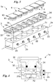
- reference numeral 1 globally denotes the multi-well plate.
- the wells 10 have extension axes 10a substantially parallel to each other.
- They are arranged in one or more rows appropriately substantially parallel to each other and, preferably, practically equidistant from each other.
- the multi-well plate 1 has twenty-four wells 10 arranged in four rows of six wells 10. It is to be noted how in some cases the multi-well plate 1 may have a different number of rows of wells (appropriately of six wells) optionally at least partly not evenly spaced.
- the multi-well plate 1 may have dimensions substantially equal to those of conventional multi-well plates.
- it may have a length and a width measured perpendicular to the preferred extension axes 10a, practically respectively comprised between 12 cm and 14 cm and between 7 cm and 10 cm and, more specifically, between 12.5 cm and 13 cm and between 8.3 cm and 8.8 cm.
- the multi-well plate 1 comprises a plurality of culture modules 1a suitable to be constrained, preferably detachably, to each other to form the multi-well plate 1.
- the operator may decide at will, to use a number of modules 1a connected to each other to form a multi-well plate 1 of a length, measured perpendicular to the lying plane of the axes 10a of a row of wells 10, which varies depending on the number of modules 1a used, even equal to the length of a standard multi-well plate.
- the multi-well plate 1 may thus present different configurations which differ from each other by the number of wells 10 and their size. In particular, such configurations are the same as conventional multi-well plates and described above.
- Each culture module 1a comprises a lower body 2 comprising at least one chamber 10b of at least one well 10; an upper body 3 comprising at least one introduction opening 10c of said at least one well 10; and at least one lid 4 suitable to fit into said at least one well 10 leaving only the chamber 10b free.
- each culture module 1a comprises the chambers 10b of the wells 10 arranged in a row; an upper body 3 comprising the introduction openings 10c of the wells 10 arranged in a row; and at least one lid 4 suitable to fit into the wells 10 leaving free only the chamber 10b.
- the lower body 2, the upper body 3 and the lid 4 are substantially transparent to light and, in particular, made of glass or other plastic material suitable to permit visibility through them.
- the lower body 2 is a single piece of material suitably chosen from polymethylacrylate, polystyrene and polycarbonate (preferably makrolon®).
- the lower body 2 further defines an axis 2b transverse to the longitudinal axis 2a and, preferably, almost perpendicular to the axes, 2a and 10a.
- the lower body 2 has a length, measured along the preferred extension axis 2a, substantially equal to the width of the multi-well plate 1.
- It comprises a base block on which, for each of the wells 10 in a row, a bottom portion 2c of the well 10 is made including at least the chamber 10b and, appropriately, a supplementary part of the well 10 identifying the engagement portion of said well 10 to the lid 4.
- the lower body 2 further comprises at least one channel to place in fluidic through connection two or more chambers 10b of adjacent modules 1a.
- it comprises, for each well 10, at least one input channel 21 and at least one output channel 22 suitable to allow a fluid to respectively enter and exit the chamber 10b.
- it may comprise at least one additional channel transverse and, in particular, substantially perpendicular to said channels 21 and 22 to place in fluid through connection two or more chambers 10b of a culture module 1a.
- the channels 21 and 22 are substantially parallel to each other and, preferably, have almost the same extension axis. More preferably, the extension axis of the channels 21 and 22 is practically parallel to the transverse axis 2b.
- the plate 1 comprises hydraulic connectors 5 placed at each output channel 22 and suitable to engage the input channel 21 of an adjacent culture module placing in fluidic connection the channels 21 and 22.
- the connectors 5 are integral with the lower body 2 and protrude from it so as to fit into a bored portion 21a of the input channel 21 of the adjacent module 2 and detachably constraining it, preferably by interlocking, to said input channel 21.
- interlocking preferably identifies an interference coupling, i.e. a constraint suitable to ensure interference between the hole, in this case the bored portion 21a, and the element inserted in the hole, in this case the hydraulic connector 5 so as to be airtight and prevent the passage of fluid at the connection area between the hole and element inserted.
- interlocking identifies a coupling in which the maximum size of the hole is almost less than or, more specifically, substantially equal to the minimum size of the object to be inserted in the hole.
- the hydraulic connector 5 may provide for an o-ring or other similar element.
- the hydraulic connectors 5 are made of a material appropriately chosen from polymethylacrylate, polystyrene and polycarbonate (preferably makrolon®).
- the multi-well plate 1 comprises one or more hydraulic taps, appropriately three or more ways, suitable to control the fluidic through connection between adjoining chambers 10b and, thus, to adjust the size and control the direction of the flow of liquid between chambers 10b of the plate 1 through the channels 21 and 22.
- Said taps are connectable to at least one hydraulic connector 5 so as to place themselves between the channels 21 and 22 of adjacent modules 1a so as to allow the variation at will of the direction of the flow of liquid and thus the topology of the fluidic circuit crossing the chamber 10b and the channels 21 and 22.
- the input 21 and output channels 22 and optionally the hydraulic connectors can place the chambers 10b in fluidic through connection with the outside defining an incoming/outgoing flow from the plate 1 crossing the chambers 10b.
- the lower body 2 may also comprise connection means 23 suitable to connect, appropriately along the axes 10a and 2a, two adjacent lower bodies 2.
- connection means 23 may comprise holes made on the lower body 2 extending substantially parallel to the transverse axis 2b; and pins suitable to engage detachably, appropriately by interlocking, with the holes, connecting two adjacent lower bodies 2 to each other.
- the upper body 3 comprises, for each of the wells 10 in a row, an apex portion 3a comprising the introduction section 10c and complementing the bottom portion 2c. It comprises a base plate 31, appropriately rectangular, defining an extension axis practically parallel to the longitudinal axis 2a; and constraint means 32 suitable to constrain the upper body 3 to a lower body 2 of an adjacent culture module 1a.
- the plate 31 comprises the apex portions 3a of a row of wells 10.
- the plate 31 has a length and width, respectively calculated along the longitudinal 2a and transverse 2b axes, almost identical to the lower body 2.
- the plate 31 and, therefore, the upper body 3 are suitable to rest on the lower body 2 defining, with respect to said lower body 2, a cantilever portion of the upper body 3 suitable to rest on a lower body 2 of an adjacent culture module 1a.
- the cantilevered portion does not overlap the bottom portions 2c of the adjacent culture module 1a.
- the means of constraint 32 are suitable to constrain two adjacent culture modules 1a, appropriately along the transverse axis 2b, placing the longitudinal axes 2a substantially parallel to each other, and preferably the lower bodies 2 substantially in mutual contact.
- the means of constraint 32 preferably comprise pins suitable to detachably engage, preferably by interlocking, to seats 24 made on the lower body 2.
- Said pins may be integral with the plate 31 and, in particular, identify protrusions of the plate 31 appropriately perpendicular to the axes 2a and 2b.
- the plate 31 presents additional seats on the cantilever portion suitable to overlap the seats 24 so that the pins 32 detachably engage, preferably by interlocking, both seats realising the constraint between the upper body 3 and the lower body 2 of an adjacent culture module 1a.
- the upper body 3 comprises, protruding from the plate 31 on the side opposite the support surface of the lower body 2, one or more partitions 33 placed between adjoining introduction sections 10c defining distinct and separate portions of plate each comprising a single section 10c isolated from the other sections 10c; and, appropriately, an at least partial beading 34 of the plate 31 designed to isolate the sections 10c of adjacent upper bodies 3 from each other.
- the walls 33 are practically parallel to each other and appropriately extend substantially parallel to the transverse axis 2b.
- the beading 34 is preferably made on a portion of the perimeter of the plate 31 and, in particular, on the two sides practically parallel to the transverse axis 2b and on one of the sides substantially parallel to the longitudinal axis 2a.
- It has a height, measured along the preferred extension axis, practically at least equal, in detail, practically greater and more specifically, almost at least twice the height, measured along the extension axis 10a, of the partition walls 33.
- the upper body 3 is in a single piece, preferably in a material suitably chosen from polymethylacrylate, polystyrene and polycarbonate (preferably makrolon®).
- the lid 4 is designed to fit into one or more of the wells 10 arranged in a row, through the relevant sections 10c, occupying almost the entire apex portion 3a and partially the bottom portion 2c and therefore, leaving free only the chamber 10b and constraining the upper body 3 to the lower body 2.
- It therefore comprises at least one insert 41 each of which suitable to insert itself, through the introduction section 10c, in a bottom portion 2c detachably constraining itself to it; and at least one head 42 suitable to abut with the upper body 3 and particularly with the plate 31, which are thus enclosed between said head 42 and lower body 2.
- each culture module 1a comprises a plurality of lids 4, each of which suitable to insert itself, independently of the other lids 4, and to detachably constrain itself to a single well 10 and, consequently, comprising a single insert 41 and a single head 42.
- the insert 41 presents a cross-section substantially the same as that of the well 10 so as to detachably constrain itself to it, substantially by interlocking.
- the head 42 is suitable to come into direct contact with the plate 31 placing itself between adjacent partition walls 33.
- the insert 41 has a greater cross-section than the insert 41, and in detail, an almost rectangular shape and, more specifically, almost square with a side appropriately substantially equal to the distance between adjacent partition walls 33.
- the insert 41 and the head 42 are in a single piece, preferably in a material appropriately chosen from polymethylacrylate, polystyrene and polycarbonate (preferably makrolon®).
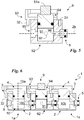
- the lid 4 may comprise a sealing element, such as an o-ring suitable to engage the well 10, increasing the water tightness of the chamber 10b ( figs. 2 and 4 ).
- the multi-well plate 1 may comprise at least one dividing group 7 suitable to be housed in a chamber 10b so as to divide said chamber 10b into a first sub-chamber, proximal to the input section, and a second sub-chamber proximal to the bottom of the well 10.
- the dividing group 7 comprises a membrane 71 suitable to define the partition wall between the sub-chambers; and at least a foot 72 preferably at least three, suitable to rest on the bottom of the well defining the distance between the membrane 71 and the bottom of the well 10, and thus the height of the sub-chambers 10 d and 10e.
- the membrane 71 is substantially counter-shaped to the well 10 so that the possible passage of substances and fluids between the sub-chambers is only possible through said membrane.
- the membrane 71 is porous, i.e. presents pores suitable to allow the passage between the sub-chambers of substances of a size slightly less than the size of the pores.
- the feet 72 have a length substantially between 4 mm and 10 mm.
- They are preferably made of a material appropriately chosen from polymethylacrylate, polystyrene and polycarbonate (preferably makrolon®).
- the lower body 2 may provide, for one or more of the chambers 10b, two input channels 21 and two output channels 22 so as to have distinct flows between the sub-chambers.
- the multi-well plate 1 may provide for caps 8 each of which suitable to detachably engage, preferably by interlocking, to one of the channels 21 and 22 preventing outputs of fluid.
- the cap 8 comprises a closure element practically counter-shaped to the channels 21 and 22 so as to detachably engage, by interlocking, to said channels; and, preferably, an abutment suitable to rest on the lower body and, therefore, not fit in the channels 21 and 22 favoring the removal of the caps.
- the multi-well plate 1 may include at least one adjustment module 9 ( Fig. 5 ) comprising at least one housing and one or more adjustment members 9 and suitable to interpose and constrain itself to two adjacent culture modules 1a placing said at least one housing and said adjustment member 9 in fluidic through connection and interposed to the chambers 10b.
- at least one adjustment module 9 ( Fig. 5 ) comprising at least one housing and one or more adjustment members 9 and suitable to interpose and constrain itself to two adjacent culture modules 1a placing said at least one housing and said adjustment member 9 in fluidic through connection and interposed to the chambers 10b.
- the adjustment module 9 may be structurally analogous to the culture module and comprises an additional lower body 92 defining at least a housing; an additional upper body 93; and an additional lid 94 designed to fit into said at least one housing constraining the additional lower body 92 to the additional upper body 93.
- the additional bodies 93 and 92 and the additional lid 94 may be of a material suitably chosen from polymethylacrylate, polystyrene and polycarbonate (preferably makrolon®).
- the adjustment module 9 may comprise at least one of the above described constraint means 32 (suitably associated to the upper body 93) and said seats 24 suitably made on the additional lower body 92.
- the adjustment module 9 may comprise only one out of the above described constraint means 32 and said seats 24.
- the adjustment module 9 may comprise both the above described constraint means 32 and said seats 24 placed on opposite sides to the means 32 relative to the housing.
- the constraint means 32 may comprise one or more pins protruding from cantilevered portions of the additional upper body 93 and suitable to fit into seats 24 made on the lower body 2 of an adjacent culture module 1a.
- the additional lower body 92 may include the aforementioned connection means 23 so as to be connected, suitably along the axes 2a and 2b, to adjacent lower bodies 2 and, therefore, to adjacent culture modules 1a.
- the additional lid 94 may comprise, in a similar manner to the lid 4, at least one insert, each of which suitable to fit into a housing of the additional lower body 92 detachably engaging itself to it; and, optionally, at least an additional head suitable to abut against the additional upper body 93 and enclosing it between said additional head and the additional lower body 92.
- Each adjustment member 91 is suitable to be placed in fluidic through connection between at least one chamber 10b of a first of the culture modules 1a between which the adjustment module 9 and at least one chamber 10b of the second of such culture modules 1a is enclosed, so as to regulate the flow of fluid between the chamber 10b of the first culture module 1a and the chamber 10b of the second culture module 1a.
- Each adjustment member 91 is suitable to vary at least the direction (and optionally the orientation) of advancement of the fluid in the multi-well plate 1.
- It may comprise a valve, a two or three-way tap, a throttle diaphragm. Preferably, they are three-way valves.
- the adjustment member 91 may be provided with control means 91a suitable to allow an operator to control the adjustment member 91.
- control means 91a may be suitable to control a variation of the direction of fluid flow as a function of a rotation of the adjustment member 91 and, in some cases, of the additional lid 94.
- the adjustment module 9 may comprise at least one inlet duct 95 and at least one outlet duct 96 suitable to allow a fluid to enter and exit said seat and, therefore, said adjustment members 91.
- the ducts 95 and 96 are substantially parallel to each other and to the channels 21 and 22 and, preferably, have practically the same extension axis. More preferably, the extension axis of the ducts 95 and 96 is practically parallel to the transverse axis 2b.
- the adjustment module 9 may comprise at least one additional transverse duct 97, in particular substantially perpendicular to said ducts 95 and 96 and suitable to place in fluid through connection two or more seats and thus two or more adjustment members 91. More optionally, said transverse duct 97 can place in fluidic through connection a seat and, thus, an adjustment member with the outside allowing the insertion and/or extraction of a fluid from the multi-well plate 1.
- the multi-well plate 1 may comprise one or more of said hydraulic connectors 5 placed at each outlet duct 22 and suitable to engage to the input channel 21 of a culture module 1a, placing an outlet duct 82 and an input channel 21 in fluidic through connection.
- the connectors 5 are integral with the adjustment module 9 and protrude from it so as to be inserted in said bored portion 21a.
- inlet duct 95 can have its own bored engagement portion to the hydraulic connector of a culture module 1a.
- the assembly method of a multi-well plate, described above in a structural sense, is as follows.
- the method provides for at least one positioning step in which two or more culture modules 1a are placed alongside along the transverse axis 2b; at least one constraint step of two adjacent culture modules; and at least one anchoring step of the upper body 3 to its lower body 2.
- the channels 21 and 22 are placed in connection using the hydraulic connectors 5.
- the upper body 3 of a first culture module 1a is placed on a lower body 2 of said first culture module 1a and preferably at the same time, constrained to a second culture module next to the first culture module 1a.
- the lid 4 of the first culture module 1a is inserted in one or more of the wells 10 of the first culture module 1a engaging itself to the lower body 2 of the first culture module 1a so as to clamp the upper body 3 of the first culture module 1a between the lower body 2 of the first culture module 1a and said lid 4 of the first culture module 1a.
- At least one insert 41 is inserted through the introduction section 10c, in a bottom portion 2c detachably constraining itself to it and bringing the corresponding head 42 in abutment with the upper body 3 which is thus enclosed and blocked between said head 42 and the lower body 2.
- the method may provide for a positioning step in which at least one culture module 1a is brought closer along the transverse axis 2b to an adjustment module 9; a constraint step between the culture module 1a and the control module 9.
- the operator places the upper body 3 on the lower body 2 so as to overlap the portions 2c and 3a forming a row of wells 10.
- the operator if he wishes to arrange the cultures on a membrane in a chamber, places the dividing group 7 in the chamber 10b, proceeding with the arrangement of the cell culture on the membrane 71.
- the operator can place a first cell culture on the base of the chamber 10b, position the dividing group 7 in the chamber 10b and place the second cell culture on the membrane 71.
- the operator constrains, for each chamber filled with at least one culture, the lid 4 to the lower body 2 so as to lock the bodies 2 and 3 together, closes the chamber 10b and assembles a culture module 1a.
- the operator closes each well 10 with a lid 4.
- the operator may now proceed with filling the chamber 10b by means of the channels 21 or alternatively fill one or more bottom portions before securing the cover 4.
- the operator determines a first order of mutual arrangement of the culture modules 1a. Then, according to said order, he connects, thanks to the hydraulic connectors 5, the channels 21 and 22 of adjacent modules 1a and, thanks to the means of constraint 32, blocks together the culture modules 1a forming the multi-well plate 1.
- the operator can use the channels 21 and 22 to place the chambers 10b in connection with an external feeding system so as to control and vary the type, intensity and characteristics of the flow crossing said chambers.
- the operator wishes to replace one or more of the cell cultures to be fed, he simply disassembles the plate 1, replaces one or more of the previous culture modules 1a with new ones, reassembles the plate using said new culture modules 1a and replenishes the cultures with a different fluid.
- the invention achieves important advantages.
- a first important advantage is the ability to detach and attach the modules 1a to each other at will, i.e. is to be identified in the highly modular nature and thus the capacity of the multi-well plate 1 to adapt to the needs of the operator.
- the possibility of varying the arrangement of the modules 1a makes it possible to vary, in a simple and fast manner, the order in which a fluid crosses the culture chambers and consequently the tissues placed in communication. Another advantage is the fact that such changes can be made leaving the chamber 10b closed and thus avoiding contamination of the cutures.
- Another advantage related to the modularity of the multi-well plate 1 is to be identified in the fact that if the operator wishes, he can access the chambers 10b individually and, thus expose the cultures grown in the wells 10 to aerosols, according to the experimental needs.
- the operator may provide one or more lids 4 with a hydrodynamic stimulation system or cyclic compression of the cultures and having an immersion body suitable to be immersed in the fluid present in a chamber 10b and a linear actuator suitable to move, preferentially along the axis 10a, the immersion body according to a law of motion as a function of the experimental needs.
- a further advantage of no less importance is the modularity of the multi-well plate 1 given by the possibility of varying the culture modules 1a forming a multi-well plate 1 without incurring in contamination of the cell cultures.
- the lower body 2 may be made in two or more units each of which comprises a single bottom portion 2c and, preferably, the channels 21 and 22.
- Each unit is lastly fitted with coupling means suitable to allow the units to be mutually detachably constrained, appropriately, by interlocking.
- the units are in a material suitably chosen from polymethylmetacrylate, polystyrene and polycarbonate (makrolon®preferably).
Landscapes
- Health & Medical Sciences (AREA)
- Chemical & Material Sciences (AREA)
- Zoology (AREA)
- Life Sciences & Earth Sciences (AREA)
- Engineering & Computer Science (AREA)
- Bioinformatics & Cheminformatics (AREA)
- Organic Chemistry (AREA)
- Wood Science & Technology (AREA)
- Clinical Laboratory Science (AREA)
- General Health & Medical Sciences (AREA)
- Biomedical Technology (AREA)
- Sustainable Development (AREA)
- Biochemistry (AREA)
- General Engineering & Computer Science (AREA)
- Microbiology (AREA)
- Genetics & Genomics (AREA)
- Biotechnology (AREA)
- Analytical Chemistry (AREA)
- Hematology (AREA)
- Chemical Kinetics & Catalysis (AREA)
- Apparatus Associated With Microorganisms And Enzymes (AREA)
Claims (14)
- Plaquette à puits multiples (1) pour cultures cellulaires comprenant- une pluralité de puits (10) disposés en rangées ;- chacun desdits puits (10) définissant une chambre (10b) apte à contenir lesdites cultures cellulaires et une section d'introduction (10c) desdites cultures cellulaires dans ladite chambre (10b) ;- caractérisée en ce qu'elle comprend des modules de culture (1a) aptes à être liés l'un à l'autre en réalisant ladite plaquette à puits multiples (1) ;- en ce que chacun desdits modules de culture (1a) comprend- un corps inférieur (2) comprenant au moins une partie de fond (2c) chacune desquelles comprenant une desdites chambres (10a) desdits puits (10) disposés le long d'une desdites rangées ;- un corps supérieur (3) comprenant des parties de sommet (3a) complémentaires desdites parties de fond (2c) et comprenant lesdites sections d'introduction (10c) desdits puits (10) dans ladite rangée, apte à être en appui sur ledit corps inférieur (2) et apte à se lier de manière amovible à un module de culture (1a) contigu ; et- au moins un couvercle (4) apte à s'insérer, à travers au moins une desdites sections d'introduction (10c), dans au moins un desdits puits (10) en s'engageant de manière amovible avec ladite partie de fond (2c) et en liant ledit corps supérieur (3) audit corps inférieur (2).
- Plaquette à puits multiples (1) selon la revendication 1, comprenant au moins un module de réglage (9) apte s'interposer et être entre deux desdits modules de culture contigus (1a) ; et dans laquelle ledit module de réglage comprend au moins un élément de réglage (91) apte à être situé en communication fluide entre au moins une chambre (10b) d'un premier desdits modules de culture (1a) et au moins une chambre (10b) d'un deuxième desdits modules de culture (1a) de façon à régler le débit du fluide entre ladite chambre (10b) dudit premier module de culture (1a) et ladite chambre (10b) dudit deuxième module de culture (1a).
- Plaquette à puits multiples (1) selon la revendication précédente, dans laquelle ledit au moins un élément de réglage (91) est apte à modifier au moins la direction d'avancement dudit fluide dans ladite plaquette à puits multiples (1).
- Plaquette à puits multiples (1) selon la revendication précédente, dans laquelle ledit au moins un élément de réglage (91) est choisi parmi une vanne, un robinet à deux voies et un robinet à trois voies.
- Plaquette à puits multiples (1) selon une ou plusieurs des revendications précédentes, dans laquelle ledit au moins un couvercle (4) est apte à s'engager à emboîtement avec ladite partie de fond (2c) en renfermant ledit corps supérieur (3) entre ledit corps inférieur (2) et ledit au moins un couvercle (4).
- Plaquette à puits multiples (1) selon la revendication précédente, dans laquelle ledit au moins un couvercle (4) comprend au moins un insert (41) chacun desquels apte à s'insérer, à travers ladite section d'introduction (10c), dans une desdites parties de fond (2c) en se liant de manière amovible avec celle-ci ; et au moins une tête (42) apte à venir en butée contre ledit corps supérieur (3) qui est ainsi renfermé entre lesdits corps inférieur (2) et ladite tête (42).
- Plaquette à puits multiples (1) selon la revendication précédente, dans laquelle ledit au moins un couvercle (4) est apte à s'engager avec un seul puit (10) et comprend un seul insert (41) et une seule tête (42).
- Plaquette à puits multiples (1) selon une ou plusieurs des revendications précédentes, dans laquelle ledit corps supérieur (3) est apte à être en appui sur ledit corps inférieur (2) en définissant, par rapport audit corps inférieur (2), une partie en porte-à-faux dudit corps supérieur (3) apte à être en appui sur ledit corps inférieur (2) d'un module de culture contigu (1a) ; et dans laquelle ledit corps supérieur (3) comprend des moyens de raccordement (32) aptes à lier ladite partie en porte-à-faux dudit corps supérieur (3) audit corps inférieur (2) dudit module de culture contigu (1a).
- Plaquette à puits multiples (1) selon une ou plusieurs des revendications précédentes, dans laquelle ledit corps supérieur (3) comprend une plaquette de base (31) comprenant lesdites parties de fond (2c) ; au moins une paroi de séparation (33) interposées entre les sections d'introduction contiguës (10c) en définissant des parties, distinctes et séparées, de ladite plaquette (31) chacune desquelles comprenant une section d'introduction (10c) unique.
- Plaquette à puits multiples (1) selon la revendication précédente, une bordure (34) apte à isoler des sections d'introduction (10c) l'une de l'autre des corps supérieurs (3) contigus.
- Plaquette à puits multiples (1) selon une ou plusieurs des revendications précédentes, dans laquelle ledit corps inférieur (2), ledit corps supérieur (3) et ledit au moins un couvercle (4) sont fait d'un matériau choisi de manière adéquate parmi du polyméthacrylate, du polystyrène et du polycarbonate.
- Plaquette à puits multiples (1) selon la revendication précédente, dans laquelle ledit corps inférieur (2), ledit corps supérieur (3) et ledit au moins un couvercle (4) sont transparents.
- Plaquette à puits multiples (1) selon une ou plusieurs des revendications précédentes, dans laquelle ledit corps inférieur (2) comprend, pour chacun desdits puits (10) dans ladite rangée, un conduit d'entrée (21) et un conduit de sortie (22) aptes à relier en communication de fluide la chambre (10b) des modules de culture contigus (1a) ; et dans laquelle ladite plaquette à puits multiples (1) comprend au moins un robinet hydraulique, apte à permettre de contrôler ladite communication fluide.
- Procédé d'assemblage d'une plaquette à puits multiples (1) selon une ou plusieurs des revendications précédentes ; ledit procédé d'assemblage étant caractérisé en ce qu'il comprend- au moins une étape de positionnement dans laquelle deux desdits modules de culture (1a) sont placés l'un à côté de l'autre ;- au moins une étape de raccordement dans laquelle ledit corps supérieur (3) d'un premier desdits modules de culture (1a) est en appui sur un corps inférieur (2) dudit premier module de culture (1a) et lié au corps inférieur (2) d'un deuxième desdits modules de culture (1a) contigu audit premier module de culture (1a) ; et- au moins une étape d'arrimage dans laquelle ledit corps supérieur (3) dudit premier module de culture (1a) est lié audit propre corps inférieur (2) dudit premier module de culture (1a) en bloquant ledit corps supérieur (3) dudit premier module de culture (1a) entre ledit corps supérieur (3) dudit premier module de culture (1a) et ledit propre corps inférieur (2) dudit premier module de culture (1a).
Applications Claiming Priority (1)
| Application Number | Priority Date | Filing Date | Title |
|---|---|---|---|
| ITUB2015A001992A ITUB20151992A1 (it) | 2015-07-08 | 2015-07-08 | Piastra multi-pozzetto per colture cellulari |
Publications (2)
| Publication Number | Publication Date |
|---|---|
| EP3115449A1 EP3115449A1 (fr) | 2017-01-11 |
| EP3115449B1 true EP3115449B1 (fr) | 2020-09-09 |
Family
ID=54364458
Family Applications (1)
| Application Number | Title | Priority Date | Filing Date |
|---|---|---|---|
| EP16178341.0A Active EP3115449B1 (fr) | 2015-07-08 | 2016-07-07 | Plaquette à puits multiples pour cultures cellulaires |
Country Status (2)
| Country | Link |
|---|---|
| EP (1) | EP3115449B1 (fr) |
| IT (1) | ITUB20151992A1 (fr) |
Cited By (1)
| Publication number | Priority date | Publication date | Assignee | Title |
|---|---|---|---|---|
| WO2025237604A1 (fr) * | 2024-05-17 | 2025-11-20 | Universität Zürich | Plaque de microtitration en plusieurs parties |
Families Citing this family (8)
| Publication number | Priority date | Publication date | Assignee | Title |
|---|---|---|---|---|
| US20210388302A1 (en) * | 2018-10-09 | 2021-12-16 | Cellectricon Ab | Compartmentalized cell cultures for usage in high capacity applications |
| WO2020109865A1 (fr) * | 2018-11-29 | 2020-06-04 | Novartis Ag. | Modèles de perfusion multi-organe à haut débit |
| CN111471572B (zh) * | 2020-04-20 | 2021-02-12 | 贵州金域医学检验中心有限公司 | 一种用于细胞检测的试剂盒 |
| EP4001397A1 (fr) | 2020-11-19 | 2022-05-25 | Real Research Sp. z o.o. | Cuvette, cassette et système de croissance 3d macroscopique et traitement de cellules |
| WO2022222059A1 (fr) * | 2021-04-21 | 2022-10-27 | 中国科学院深圳先进技术研究院 | Appareil de traitement |
| US20230149919A1 (en) * | 2021-11-15 | 2023-05-18 | Tissue Testing Technologies Llc | Cassette for preservation of natural and bioengineered tissues |
| EP4403622A1 (fr) * | 2023-01-17 | 2024-07-24 | The Automation Partnership (Cambridge) Ltd. | Récipient intelligent pour la réalisation d'un bioprocédé et contenant un matériau biologique, en particulier des cultures de cellules immunitaires liquides |
| WO2025134045A1 (fr) | 2023-12-21 | 2025-06-26 | Politecnico Di Milano | Dispositif de bioréacteurs modulaire et kit associé |
Family Cites Families (9)
| Publication number | Priority date | Publication date | Assignee | Title |
|---|---|---|---|---|
| US4948564A (en) * | 1986-10-28 | 1990-08-14 | Costar Corporation | Multi-well filter strip and composite assemblies |
| US6096562A (en) * | 1997-10-27 | 2000-08-01 | Nalge Nunc International Corporation | Multi-slide assembly including slide, frame and strip cap, and methods thereof |
| US7128878B2 (en) | 2002-10-04 | 2006-10-31 | Becton, Dickinson And Company | Multiwell plate |
| US20070077181A1 (en) | 2005-10-04 | 2007-04-05 | Youngbear Kathy M | Multiwell plate with modified rib configuration |
| US7531140B2 (en) | 2005-12-29 | 2009-05-12 | Corning Incorporated | Multiwell plate having transparent well bottoms and method for making the mulitiwell plate |
| WO2008143888A1 (fr) | 2007-05-14 | 2008-11-27 | Erie Scientific Company | Dispositif de plaque multipuits |
| EP2257376A1 (fr) | 2008-02-20 | 2010-12-08 | ETH Zurich | Plaque de culture à puits multiples destinée à des cultures tridimensionnelles |
| CN202201886U (zh) * | 2011-09-09 | 2012-04-25 | 郑州博赛生物技术股份有限公司 | 一种可拆分阴道炎联合检测板 |
| CN202482308U (zh) * | 2012-03-19 | 2012-10-10 | 三明市和众生物技术有限公司 | 一种特殊微生物使用含特种气体的培养、药敏一体检测板 |
-
2015
- 2015-07-08 IT ITUB2015A001992A patent/ITUB20151992A1/it unknown
-
2016
- 2016-07-07 EP EP16178341.0A patent/EP3115449B1/fr active Active
Non-Patent Citations (1)
| Title |
|---|
| None * |
Cited By (1)
| Publication number | Priority date | Publication date | Assignee | Title |
|---|---|---|---|---|
| WO2025237604A1 (fr) * | 2024-05-17 | 2025-11-20 | Universität Zürich | Plaque de microtitration en plusieurs parties |
Also Published As
| Publication number | Publication date |
|---|---|
| EP3115449A1 (fr) | 2017-01-11 |
| ITUB20151992A1 (it) | 2017-01-08 |
Similar Documents
| Publication | Publication Date | Title |
|---|---|---|
| EP3115449B1 (fr) | Plaquette à puits multiples pour cultures cellulaires | |
| JP7231619B2 (ja) | ウェルプレートアセンブリ | |
| JP7171696B2 (ja) | 相互接続されたウェルを有するマイクロプレートを備えた流体デバイス | |
| CN107022482B (zh) | 多个灌注工程组织构建和微型生化分析仪的互联,多个微型配方设计模块及其应用 | |
| US5554536A (en) | Biological analysis device having improved contamination prevention | |
| KR102448151B1 (ko) | 서열분석 디바이스 | |
| ES2983869T3 (es) | Procedimiento para enriquecer gas y simultáneamente desplazar un fluido, y sistema para el control del entorno celular sobre una placa de cultivo celular de múltiples pocillos correspondiente | |
| JP2007504816A (ja) | 細胞、胚または、卵母細胞を取り扱う装置と方法 | |
| JPWO2017154880A1 (ja) | 細胞培養装置および細胞培養方法 | |
| JP2018515146A (ja) | インビトロ3d細胞培養実験のためのマイクロ流体デバイス | |
| ES2897966T3 (es) | Receptáculo de portaobjetos autónomo para especímenes de paciente | |
| CN219861383U (zh) | 细胞培养单元及细胞培养装置 | |
| CN109055204B (zh) | 药物筛选用器官芯片 | |
| US12508588B2 (en) | Biomechanical testing system and reactor module thereof | |
| CN120682933A (zh) | 一种高通量类器官培养液芯器件 | |
| TWI788850B (zh) | 生物力學測試系統及其反應器模組 | |
| AU2020349664B2 (en) | Millifluidic device for advanced cultures of biological agents | |
| US11767498B2 (en) | In vitro tissue plate | |
| KR102955146B1 (ko) | 세포 배양 플레이트 및 세포 배양 플레이트 적층 배열체 | |
| WO2021206555A1 (fr) | Dispositif fluidique, système de culture cellulaire et procédé d'essai d'un composé | |
| TWI909490B (zh) | 用於模擬生理屏障環境之器官晶片總成、微流道裝置及模擬生理屏障環境的方法 | |
| EP4556119A1 (fr) | Système de distribution de liquide pour puce fluidique | |
| ITMI20112073A1 (it) | Supporto per camere di coltura cellulare | |
| US20260078328A1 (en) | Microphysiological system | |
| TWI788849B (zh) | 反應器模組及具有該反應器模組的生物力學測試系統 |
Legal Events
| Date | Code | Title | Description |
|---|---|---|---|
| PUAI | Public reference made under article 153(3) epc to a published international application that has entered the european phase |
Free format text: ORIGINAL CODE: 0009012 |
|
| STAA | Information on the status of an ep patent application or granted ep patent |
Free format text: STATUS: THE APPLICATION HAS BEEN PUBLISHED |
|
| AK | Designated contracting states |
Kind code of ref document: A1 Designated state(s): AL AT BE BG CH CY CZ DE DK EE ES FI FR GB GR HR HU IE IS IT LI LT LU LV MC MK MT NL NO PL PT RO RS SE SI SK SM TR |
|
| AX | Request for extension of the european patent |
Extension state: BA ME |
|
| STAA | Information on the status of an ep patent application or granted ep patent |
Free format text: STATUS: REQUEST FOR EXAMINATION WAS MADE |
|
| 17P | Request for examination filed |
Effective date: 20170609 |
|
| RBV | Designated contracting states (corrected) |
Designated state(s): AL AT BE BG CH CY CZ DE DK EE ES FI FR GB GR HR HU IE IS IT LI LT LU LV MC MK MT NL NO PL PT RO RS SE SI SK SM TR |
|
| GRAP | Despatch of communication of intention to grant a patent |
Free format text: ORIGINAL CODE: EPIDOSNIGR1 |
|
| STAA | Information on the status of an ep patent application or granted ep patent |
Free format text: STATUS: GRANT OF PATENT IS INTENDED |
|
| INTG | Intention to grant announced |
Effective date: 20200414 |
|
| GRAS | Grant fee paid |
Free format text: ORIGINAL CODE: EPIDOSNIGR3 |
|
| GRAA | (expected) grant |
Free format text: ORIGINAL CODE: 0009210 |
|
| STAA | Information on the status of an ep patent application or granted ep patent |
Free format text: STATUS: THE PATENT HAS BEEN GRANTED |
|
| AK | Designated contracting states |
Kind code of ref document: B1 Designated state(s): AL AT BE BG CH CY CZ DE DK EE ES FI FR GB GR HR HU IE IS IT LI LT LU LV MC MK MT NL NO PL PT RO RS SE SI SK SM TR |
|
| REG | Reference to a national code |
Ref country code: GB Ref legal event code: FG4D |
|
| REG | Reference to a national code |
Ref country code: AT Ref legal event code: REF Ref document number: 1311598 Country of ref document: AT Kind code of ref document: T Effective date: 20200915 Ref country code: CH Ref legal event code: EP |
|
| REG | Reference to a national code |
Ref country code: IE Ref legal event code: FG4D |
|
| REG | Reference to a national code |
Ref country code: DE Ref legal event code: R096 Ref document number: 602016043577 Country of ref document: DE |
|
| REG | Reference to a national code |
Ref country code: LT Ref legal event code: MG4D |
|
| PG25 | Lapsed in a contracting state [announced via postgrant information from national office to epo] |
Ref country code: LT Free format text: LAPSE BECAUSE OF FAILURE TO SUBMIT A TRANSLATION OF THE DESCRIPTION OR TO PAY THE FEE WITHIN THE PRESCRIBED TIME-LIMIT Effective date: 20200909 Ref country code: HR Free format text: LAPSE BECAUSE OF FAILURE TO SUBMIT A TRANSLATION OF THE DESCRIPTION OR TO PAY THE FEE WITHIN THE PRESCRIBED TIME-LIMIT Effective date: 20200909 Ref country code: SE Free format text: LAPSE BECAUSE OF FAILURE TO SUBMIT A TRANSLATION OF THE DESCRIPTION OR TO PAY THE FEE WITHIN THE PRESCRIBED TIME-LIMIT Effective date: 20200909 Ref country code: NO Free format text: LAPSE BECAUSE OF FAILURE TO SUBMIT A TRANSLATION OF THE DESCRIPTION OR TO PAY THE FEE WITHIN THE PRESCRIBED TIME-LIMIT Effective date: 20201209 Ref country code: FI Free format text: LAPSE BECAUSE OF FAILURE TO SUBMIT A TRANSLATION OF THE DESCRIPTION OR TO PAY THE FEE WITHIN THE PRESCRIBED TIME-LIMIT Effective date: 20200909 Ref country code: BG Free format text: LAPSE BECAUSE OF FAILURE TO SUBMIT A TRANSLATION OF THE DESCRIPTION OR TO PAY THE FEE WITHIN THE PRESCRIBED TIME-LIMIT Effective date: 20201209 Ref country code: GR Free format text: LAPSE BECAUSE OF FAILURE TO SUBMIT A TRANSLATION OF THE DESCRIPTION OR TO PAY THE FEE WITHIN THE PRESCRIBED TIME-LIMIT Effective date: 20201210 |
|
| REG | Reference to a national code |
Ref country code: AT Ref legal event code: MK05 Ref document number: 1311598 Country of ref document: AT Kind code of ref document: T Effective date: 20200909 |
|
| REG | Reference to a national code |
Ref country code: NL Ref legal event code: MP Effective date: 20200909 |
|
| PG25 | Lapsed in a contracting state [announced via postgrant information from national office to epo] |
Ref country code: RS Free format text: LAPSE BECAUSE OF FAILURE TO SUBMIT A TRANSLATION OF THE DESCRIPTION OR TO PAY THE FEE WITHIN THE PRESCRIBED TIME-LIMIT Effective date: 20200909 Ref country code: LV Free format text: LAPSE BECAUSE OF FAILURE TO SUBMIT A TRANSLATION OF THE DESCRIPTION OR TO PAY THE FEE WITHIN THE PRESCRIBED TIME-LIMIT Effective date: 20200909 Ref country code: PL Free format text: LAPSE BECAUSE OF FAILURE TO SUBMIT A TRANSLATION OF THE DESCRIPTION OR TO PAY THE FEE WITHIN THE PRESCRIBED TIME-LIMIT Effective date: 20200909 |
|
| PG25 | Lapsed in a contracting state [announced via postgrant information from national office to epo] |
Ref country code: PT Free format text: LAPSE BECAUSE OF FAILURE TO SUBMIT A TRANSLATION OF THE DESCRIPTION OR TO PAY THE FEE WITHIN THE PRESCRIBED TIME-LIMIT Effective date: 20210111 Ref country code: RO Free format text: LAPSE BECAUSE OF FAILURE TO SUBMIT A TRANSLATION OF THE DESCRIPTION OR TO PAY THE FEE WITHIN THE PRESCRIBED TIME-LIMIT Effective date: 20200909 Ref country code: SM Free format text: LAPSE BECAUSE OF FAILURE TO SUBMIT A TRANSLATION OF THE DESCRIPTION OR TO PAY THE FEE WITHIN THE PRESCRIBED TIME-LIMIT Effective date: 20200909 Ref country code: CZ Free format text: LAPSE BECAUSE OF FAILURE TO SUBMIT A TRANSLATION OF THE DESCRIPTION OR TO PAY THE FEE WITHIN THE PRESCRIBED TIME-LIMIT Effective date: 20200909 Ref country code: NL Free format text: LAPSE BECAUSE OF FAILURE TO SUBMIT A TRANSLATION OF THE DESCRIPTION OR TO PAY THE FEE WITHIN THE PRESCRIBED TIME-LIMIT Effective date: 20200909 Ref country code: EE Free format text: LAPSE BECAUSE OF FAILURE TO SUBMIT A TRANSLATION OF THE DESCRIPTION OR TO PAY THE FEE WITHIN THE PRESCRIBED TIME-LIMIT Effective date: 20200909 |
|
| PG25 | Lapsed in a contracting state [announced via postgrant information from national office to epo] |
Ref country code: IS Free format text: LAPSE BECAUSE OF FAILURE TO SUBMIT A TRANSLATION OF THE DESCRIPTION OR TO PAY THE FEE WITHIN THE PRESCRIBED TIME-LIMIT Effective date: 20210109 Ref country code: AT Free format text: LAPSE BECAUSE OF FAILURE TO SUBMIT A TRANSLATION OF THE DESCRIPTION OR TO PAY THE FEE WITHIN THE PRESCRIBED TIME-LIMIT Effective date: 20200909 Ref country code: AL Free format text: LAPSE BECAUSE OF FAILURE TO SUBMIT A TRANSLATION OF THE DESCRIPTION OR TO PAY THE FEE WITHIN THE PRESCRIBED TIME-LIMIT Effective date: 20200909 Ref country code: ES Free format text: LAPSE BECAUSE OF FAILURE TO SUBMIT A TRANSLATION OF THE DESCRIPTION OR TO PAY THE FEE WITHIN THE PRESCRIBED TIME-LIMIT Effective date: 20200909 |
|
| REG | Reference to a national code |
Ref country code: DE Ref legal event code: R097 Ref document number: 602016043577 Country of ref document: DE |
|
| PG25 | Lapsed in a contracting state [announced via postgrant information from national office to epo] |
Ref country code: SK Free format text: LAPSE BECAUSE OF FAILURE TO SUBMIT A TRANSLATION OF THE DESCRIPTION OR TO PAY THE FEE WITHIN THE PRESCRIBED TIME-LIMIT Effective date: 20200909 |
|
| PLBE | No opposition filed within time limit |
Free format text: ORIGINAL CODE: 0009261 |
|
| STAA | Information on the status of an ep patent application or granted ep patent |
Free format text: STATUS: NO OPPOSITION FILED WITHIN TIME LIMIT |
|
| 26N | No opposition filed |
Effective date: 20210610 |
|
| PG25 | Lapsed in a contracting state [announced via postgrant information from national office to epo] |
Ref country code: SI Free format text: LAPSE BECAUSE OF FAILURE TO SUBMIT A TRANSLATION OF THE DESCRIPTION OR TO PAY THE FEE WITHIN THE PRESCRIBED TIME-LIMIT Effective date: 20200909 Ref country code: DK Free format text: LAPSE BECAUSE OF FAILURE TO SUBMIT A TRANSLATION OF THE DESCRIPTION OR TO PAY THE FEE WITHIN THE PRESCRIBED TIME-LIMIT Effective date: 20200909 |
|
| PG25 | Lapsed in a contracting state [announced via postgrant information from national office to epo] |
Ref country code: MC Free format text: LAPSE BECAUSE OF FAILURE TO SUBMIT A TRANSLATION OF THE DESCRIPTION OR TO PAY THE FEE WITHIN THE PRESCRIBED TIME-LIMIT Effective date: 20200909 |
|
| PG25 | Lapsed in a contracting state [announced via postgrant information from national office to epo] |
Ref country code: LU Free format text: LAPSE BECAUSE OF NON-PAYMENT OF DUE FEES Effective date: 20210707 |
|
| PG25 | Lapsed in a contracting state [announced via postgrant information from national office to epo] |
Ref country code: HU Free format text: LAPSE BECAUSE OF FAILURE TO SUBMIT A TRANSLATION OF THE DESCRIPTION OR TO PAY THE FEE WITHIN THE PRESCRIBED TIME-LIMIT; INVALID AB INITIO Effective date: 20160707 |
|
| PG25 | Lapsed in a contracting state [announced via postgrant information from national office to epo] |
Ref country code: CY Free format text: LAPSE BECAUSE OF FAILURE TO SUBMIT A TRANSLATION OF THE DESCRIPTION OR TO PAY THE FEE WITHIN THE PRESCRIBED TIME-LIMIT Effective date: 20200909 |
|
| P01 | Opt-out of the competence of the unified patent court (upc) registered |
Effective date: 20230605 |
|
| PG25 | Lapsed in a contracting state [announced via postgrant information from national office to epo] |
Ref country code: MK Free format text: LAPSE BECAUSE OF FAILURE TO SUBMIT A TRANSLATION OF THE DESCRIPTION OR TO PAY THE FEE WITHIN THE PRESCRIBED TIME-LIMIT Effective date: 20200909 |
|
| PG25 | Lapsed in a contracting state [announced via postgrant information from national office to epo] |
Ref country code: TR Free format text: LAPSE BECAUSE OF FAILURE TO SUBMIT A TRANSLATION OF THE DESCRIPTION OR TO PAY THE FEE WITHIN THE PRESCRIBED TIME-LIMIT Effective date: 20200909 |
|
| PG25 | Lapsed in a contracting state [announced via postgrant information from national office to epo] |
Ref country code: MT Free format text: LAPSE BECAUSE OF FAILURE TO SUBMIT A TRANSLATION OF THE DESCRIPTION OR TO PAY THE FEE WITHIN THE PRESCRIBED TIME-LIMIT Effective date: 20200909 |
|
| PGFP | Annual fee paid to national office [announced via postgrant information from national office to epo] |
Ref country code: IT Payment date: 20250429 Year of fee payment: 10 |
|
| PGFP | Annual fee paid to national office [announced via postgrant information from national office to epo] |
Ref country code: DE Payment date: 20250722 Year of fee payment: 10 |
|
| PGFP | Annual fee paid to national office [announced via postgrant information from national office to epo] |
Ref country code: BE Payment date: 20250722 Year of fee payment: 10 Ref country code: GB Payment date: 20250724 Year of fee payment: 10 |
|
| PGFP | Annual fee paid to national office [announced via postgrant information from national office to epo] |
Ref country code: FR Payment date: 20250723 Year of fee payment: 10 |
|
| PGFP | Annual fee paid to national office [announced via postgrant information from national office to epo] |
Ref country code: CH Payment date: 20250801 Year of fee payment: 10 |
|
| PGFP | Annual fee paid to national office [announced via postgrant information from national office to epo] |
Ref country code: IE Payment date: 20250724 Year of fee payment: 10 |