EP3115578B1 - Dispositif de papillon à commande électronique - Google Patents
Dispositif de papillon à commande électronique Download PDFInfo
- Publication number
- EP3115578B1 EP3115578B1 EP15752564.3A EP15752564A EP3115578B1 EP 3115578 B1 EP3115578 B1 EP 3115578B1 EP 15752564 A EP15752564 A EP 15752564A EP 3115578 B1 EP3115578 B1 EP 3115578B1
- Authority
- EP
- European Patent Office
- Prior art keywords
- throttle
- gear unit
- spigots
- engine
- intake passages
- Prior art date
- Legal status (The legal status is an assumption and is not a legal conclusion. Google has not performed a legal analysis and makes no representation as to the accuracy of the status listed.)
- Active
Links
Images

Classifications
-
- F—MECHANICAL ENGINEERING; LIGHTING; HEATING; WEAPONS; BLASTING
- F02—COMBUSTION ENGINES; HOT-GAS OR COMBUSTION-PRODUCT ENGINE PLANTS
- F02D—CONTROLLING COMBUSTION ENGINES
- F02D9/00—Controlling engines by throttling air or fuel-and-air induction conduits or exhaust conduits
- F02D9/08—Throttle valves specially adapted therefor; Arrangements of such valves in conduits
- F02D9/10—Throttle valves specially adapted therefor; Arrangements of such valves in conduits having pivotally-mounted flaps
- F02D9/1065—Mechanical control linkage between an actuator and the flap, e.g. including levers, gears, springs, clutches, limit stops of the like
-
- F—MECHANICAL ENGINEERING; LIGHTING; HEATING; WEAPONS; BLASTING
- F02—COMBUSTION ENGINES; HOT-GAS OR COMBUSTION-PRODUCT ENGINE PLANTS
- F02D—CONTROLLING COMBUSTION ENGINES
- F02D9/00—Controlling engines by throttling air or fuel-and-air induction conduits or exhaust conduits
- F02D9/08—Throttle valves specially adapted therefor; Arrangements of such valves in conduits
- F02D9/10—Throttle valves specially adapted therefor; Arrangements of such valves in conduits having pivotally-mounted flaps
- F02D9/107—Manufacturing or mounting details
-
- F—MECHANICAL ENGINEERING; LIGHTING; HEATING; WEAPONS; BLASTING
- F02—COMBUSTION ENGINES; HOT-GAS OR COMBUSTION-PRODUCT ENGINE PLANTS
- F02D—CONTROLLING COMBUSTION ENGINES
- F02D9/00—Controlling engines by throttling air or fuel-and-air induction conduits or exhaust conduits
- F02D9/08—Throttle valves specially adapted therefor; Arrangements of such valves in conduits
- F02D9/10—Throttle valves specially adapted therefor; Arrangements of such valves in conduits having pivotally-mounted flaps
- F02D9/109—Throttle valves specially adapted therefor; Arrangements of such valves in conduits having pivotally-mounted flaps having two or more flaps
- F02D9/1095—Rotating on a common axis, e.g. having a common shaft
-
- F—MECHANICAL ENGINEERING; LIGHTING; HEATING; WEAPONS; BLASTING
- F02—COMBUSTION ENGINES; HOT-GAS OR COMBUSTION-PRODUCT ENGINE PLANTS
- F02M—SUPPLYING COMBUSTION ENGINES IN GENERAL WITH COMBUSTIBLE MIXTURES OR CONSTITUENTS THEREOF
- F02M35/00—Combustion-air cleaners, air intakes, intake silencers, or induction systems specially adapted for, or arranged on, internal-combustion engines
- F02M35/16—Combustion-air cleaners, air intakes, intake silencers, or induction systems specially adapted for, or arranged on, internal-combustion engines characterised by use in vehicles
- F02M35/162—Motorcycles; All-terrain vehicles, e.g. quads, snowmobiles; Small vehicles, e.g. forklifts
Definitions
- the present invention relates to an electronically controlled throttle device for a two-wheeled vehicle in which throttle valves are respectively disposed in a plurality of intake passages corresponding to cylinders of an engine, and a throttle shaft is driven and rotated with a motor to synchronously open and close the throttle valves.
- a multiple throttle device is employed as a throttle device to regulate intake air to an engine in response to throttle operation of a driver.
- a multiple throttle device there is taken a configuration in which intake passages are defined in a throttle body correspondingly to individual cylinders of the engine, throttle valves are disposed in the individual intake passages and supported on a throttle shaft, and the throttle shaft is driven and rotated in response to the throttle operation to synchronously open and close the throttle valves.
- throttle devices are electronically controlled in recent years.
- a multiple throttle device which is electronically controlled (hereinafter referred to simply as electronically controlled throttle device)
- the throttle shaft is driven and rotated with a motor via a gear train of a gear unit to open and close the throttle valves. Twist of the throttle shaft in driving and rotating leads to phase displacements of the throttle valves, and eventually, differences in intake air amounts. Hence, the twist of the throttle shaft is suppressed by inputting driving force from the motor to the middle of the throttle shaft in the longitudinal direction.
- FIG. 5 is a cross-sectional plan view showing an electronically controlled throttle device of the conventional art as above.
- FIG. 6 is a partially expanded cross-sectional plan view of the periphery of a gear unit of the same.
- An electronically controlled throttle device 31 in this example is a quadruple throttle device for a 4-cylinder engine, and its throttle body is divided into a first throttle body 2 and a second throttle body 3, which are connected to each other with not-shown bolts.
- a pair of intake passages 5 #1 and 5 #2 that respectively correspond to a #1 cylinder and a #2 cylinder of an engine are defined in the first throttle body 2, and a pair of intake passages 5 #3 and 5 #4 that respectively correspond to a #3 cylinder and a #4 cylinder of the engine are defined in the second throttle body 3.
- a not-shown air cleaner is connected to the intake passages 5 #1 to 5 #4 on the opposite engine side, and moreover, fuel injection valves 6 show their tips inside the individual intake passages 5 #1 to 5 #4 .
- One throttle shaft 8 is rotatably supported in the first and second throttle bodies 2 and 3 so as to penetrate the intake passages 5 #1 to 5 #4 , and throttle valves 10 disposed in the individual intake passages 5 #1 to 5 #4 are supported on the throttle shaft 8.
- a gear unit 12 is disposed between the first and second throttle bodies 2 and 3, and a not-shown motor is connected to the gear unit 12. Driving force from the motor is transmitted to the throttle shaft 8 via a gear train 14 built in the gear unit 12, and drives and rotates the throttle shaft 8 to synchronously open and close the throttle valves 10.
- Cylindrical spigots 17 are formed at the end parts of the individual intake passages 5 #1 to 5 #4 on the engine side, the end parts of rubber joints 18 extending from individual intake ports of the engine are respectively fitted to the spigots 17, and they are fastened and fixed thereto with hose bands 19 or the like.
- Intake air introduced from the air cleaner into the intake passages 5 #1 to 5 #4 is mixed with fuel injected from the fuel injection valves 6 while being regulated in its flow rate in response to the degree of throttle opening, and is introduced into the cylinders through the rubber joints 18 and the intake ports of the engine to serve combustion.
- attachment space of the rubber joint 18 A space for fitting the end part of the rubber joint 18 (hereinafter referred to as attachment space of the rubber joint 18) is needed in the periphery of each spigot 17.
- the gear unit 12 which the gear train 14 is built in occupies a significant region in the radial direction with the throttle shaft 8 being as the center. Hence, a part thereof interferes with the spigots 17, which prevents the attachment spaces of the rubber joints 18 from being secured.
- the total lengths L 2 of the throttle bodies 2 and 3 along the intake air flowing direction are elongated to displace the positions of the spigots 17 to the engine side (separate them from the gear unit 12 by a dimension l 3 ), and thereby, the interference with a part of the gear unit 12 is prevented to secure the attachment spaces of the rubber joints 18.
- a technology in Patent Document 1 is proposed.
- the throttle device in Patent Document 1 employs conventional wire drive, and therein, a connection synchronization mechanism is provided between both throttle bodies. Throttle operation by the driver is transmitted to a throttle shaft of one throttle body via a wire, the rotation of the throttle shaft is transmitted to a throttle shaft of the other throttle body via the connection synchronization mechanism, and the connection synchronization mechanism enables a phase between the throttle shafts to be finely adjusted.
- spigots of a pair of intake passages positioned on both sides of the connection synchronization mechanism are formed to have eccentricity downward by a and formed to have eccentricity in a direction away from each other by b.
- Patent Document 1 Japanese Patent No. 4751366
- EP 1 555 408 A1 relates to a multiple throttle device.
- multi-throttle apparatus provided with multiple throttle valves that are respectively disposed in multiple intake passages, a throttle shaft that simultaneously opens/closes the throttle valves, drive means that drives the throttle shaft, and a return spring, the driving force of the drive means is applied to an approximate center of the throttle shaft, the energizing force of the return spring is applied close to the location to which the energizing force is applied, and bearings are provided in mutual intervals between the multiple intake passages to support the throttle shaft. Consequently, torsion of the throttle shaft is prevented, and the throttle valves are opened/closed synchronously without generating a phase shift. Consequently, electronic control is provided for multi-throttle apparatuses applied to engines of two-wheeled vehicles and the like, and the synchronization among throttle valves is secured.
- the length (internal volume) of the intake passage of the throttle device As one of various factors affecting the engine characteristics, there is known the length (internal volume) of the intake passage of the throttle device. It is essential for the intake passage to be made short for the characteristics of a high speed rotation-type engine desired in a two-wheeled vehicle. Nevertheless, when the total lengths of the throttle bodies 2 and 3 are elongated in order to secure the attachment spaces of the rubber joints 18, the intake passages 5 #1 to 5 #4 are also elongated, which causes the electronically controlled throttle device 31 to have improper specifications in view of the characteristics of a high speed rotation-type engine.
- the gear unit 12 In order to reduce the total lengths L 2 of the throttle bodies 2 and 3 to be compatible with the characteristics of a high speed rotation-type engine, the gear unit 12 is needed to be downsized. However, the following reason makes downsizing the gear unit 12 exceedingly difficult.
- connection synchronization mechanism for example, in Patent Document 1, an adjustment bolt is provided at a position eccentric from the rotational axis line of one throttle shaft, and a synchronization plate is provided at a position eccentric from the rotational axis line of the other throttle shaft so as to correspond to the tip of the adjustment bolt.
- the tip of the adjustment bolt transmits the rotation to the other throttle shaft while pressing the synchronization plate, and in this way, both throttle shafts synchronously rotate.
- the adjustment bolt and the synchronization plate are needed to be formed to have eccentricity with respect to the rotational axis lines of the throttle shafts, which causes the connection synchronization mechanism to be larger as the eccentric amount is larger. Nevertheless, since the rotation transmission can be performed without any problems in the presence of a certain eccentric amount, the connection synchronization mechanism can be easily downsized.
- the gear unit 12 of the conventional art is largely different from the connection synchronization mechanism disclosed in Patent Document 1 in that it cannot be easily downsized, and consequently, the problems thereof cannot be solved simply with a measure that the spigots are formed to have eccentricity as disclosed in Patent Document 1.
- the large gear unit 12 has to be disposed between both throttle bodies 2 and 3.
- to elongate the total lengths L 2 of the throttle bodies 2 and 3 for securing the attachment spaces of the rubber joints 18 has problematically caused impossibility in realizing specifications suitable for characteristics of a high speed rotation-type engine.
- the present invention is devised in order to solve such problems and an object thereof is to provide an electronically controlled throttle device in which attachment spaces of rubber joints can be secured in the peripheries of spigots without elongating throttle bodies in the intake air flowing direction in the layout of a gear unit disposed between the throttle bodies, and accordingly with which specifications suitable for characteristics of a small and lightweight high speed rotation-type engine can be realized while maintaining excellent assembly ability.
- an electronically controlled throttle device of the present invention including: a pair of throttle bodies that are disposed adjacent to each other and in each of which an intake passage corresponding to each cylinder of an engine is defined; spigots that are respectively formed in engine-side end parts of the intake passages of the throttle bodies, axis lines of which are formed to have eccentricity in a direction away from each other with axis lines of the intake passages being as references, and to each of which one end of a joint member extending from the corresponding cylinder of the engine is fitted; a throttle shaft rotatably supported in the throttle bodies and supporting throttle valves respectively disposed in the intake passages; and a gear unit that is disposed between the throttle bodies to be connected to the throttle shaft, drives and rotates the throttle shaft with driving force from a motor via a built-in gear train to be capable of synchronously opening and closing the throttle valves, and a part of which is positioned between the spigots of the throttle bodies.
- the electronically controlled throttle device configured as above, in the layout of the gear unit disposed between the throttle bodies, the total lengths of the throttle bodies in the intake air flowing direction are reduced, and the attachment spaces of the joint members can be secured in the peripheries of both spigots.
- a part of the gear unit protrudes beyond ends of the spigots of the throttle bodies to the engine side.
- a larger gear unit can be disposed between the throttle bodies, and the total lengths of the throttle bodies can be further reduced.
- a plurality of intake passages are formed in each of the throttle bodies, and only axis lines of a pair of spigots positioned on both sides of the gear unit out of the spigots respectively formed in the engine-side end parts of the intake passages are formed to have eccentricity in the direction away from each other.
- the electronically controlled throttle device configured as above, since only the axis lines of the pair of spigots positioned on both sides of the gear unit have eccentricity in the direction away and the axis lines of the other spigots do not have eccentricity, a situation that the space occupied by the spigots of the cylinders increases can be prevented, which enables further downsizing.
- the gear unit is disposed to have an offset toward any one side of the throttle bodies from a central position between axis lines of a pair of intake passages positioned on both sides of the gear unit, and that eccentric amounts of the axis lines of the spigots with respect to the respective axis lines of the pair of intake passages are configured such that the eccentric amount of the axis line of the spigot positioned on the one side of the gear unit is larger than the eccentric amount of the axis line of the spigot positioned on the other side of the gear unit.
- the attachment spaces can be more definitely secured in the peripheries of the spigots.
- attachment spaces of joint members can be secured in the peripheries of spigots without elongating throttle bodies in the intake air flowing direction in the layout of a gear unit provided between the throttle bodies, and accordingly, specifications suitable for characteristics of a small and lightweight high speed rotation-type engine can be realized while maintaining excellent assembly ability.
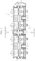
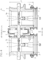
- FIG. 1 is a cross-sectional plan view showing an electronically controlled throttle device of the present embodiment.
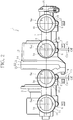
- FIG. 2 is a view of the electronically controlled throttle device as seen from the engine side through the arrow A in FIG. 1 .
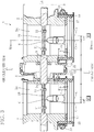
- FIG. 3 is a partially expanded cross-sectional plan view of the periphery of a gear unit of the same.
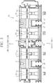
- FIG. 4 is a cross-sectional view taken along the IV-IV line in FIG. 3 .
- an electronic throttle control device in the posture of being mounted on a two-wheeled vehicle is seen from the upper side, and not shown, an engine is positioned on the downside in the figure and an air cleaner is positioned on the upside therein.
- the direction perpendicular to the page of FIG. 1 is defined as being vertical, the right-left direction in FIG. 1 as being horizontal (direction in which cylinders are provided to line up), the downside in FIG. 1 as being on the engine side, and the upside therein as being on the air cleaner side.
- an electronically controlled throttle device 1 of the present embodiment is configured as a quadruple throttle device for a 4-cylinder engine.
- a throttle body of the electronically controlled throttle device 1 is composed of a first throttle body 2 and a second throttle body 3, and these throttle bodies 2 and 3 are produced by aluminum die casting and are connected to each other with a plurality of bolts 4 ( FIG. 2 shows one of these).
- a pair of intake passages 5 #1 and 5 #2 that respectively correspond to a #1 cylinder and a #2 cylinder of the engine and have circular cross sections are defined in the first throttle body 2, and a pair of intake passages 5 #3 and 5 #4 that respectively correspond to a #3 cylinder and a #4 cylinder of the engine and have circular cross sections are defined in the second throttle body 3.
- the intake passages 5 #1 to 5 #4 are provided to line up at predetermined pitches in the horizontal direction correspondingly to the individual cylinders of the engine.
- a common air cleaner is connected to the intake passages 5 #1 to 5 #4 on the opposite engine side, and during operation of the engine, the air filtered through the air cleaner is introduced into the intake passages 5 #1 to 5 #4 .
- fuel injection valves 6 are attached to the individual intake passages 5 #1 to 5 #4 of the first and second throttle bodies 2 and 3 at the downside positions so as to show their tips inside the intake passages 5 #1 to 5 #4 , and during operation of the engine, fuel is injected from the fuel injection valves 6 into the intake passages 5 #1 to 5 #4 in response to a drive signal from a not-shown ECU (engine control unit).
- the fuel injection valves 6 corresponding to the individual cylinders are omitted.
- One throttle shaft 8 is rotatably supported on bearings 9 in the first and second throttle bodies 2 and 3, and the throttle shaft 8 extends in the horizontal direction so as to penetrate the intake passages 5 #1 to 5 #4 .
- Throttle valves 10 are disposed in the individual intake passages 5 #1 to 5 #4 , and these throttle valves 10 are fixed to the throttle shaft 8 with individual pairs of screws 11.
- a gear unit 12 is disposed between the first and second throttle bodies 2 and 3, and a motor 13 (illustrated with a broken line in FIG. 2 ) is built in the first throttle body 2.
- the output shaft of the motor 13 is connected to one end of a gear train 14 (illustrated with a broken line in FIGS. 2 and 3 ) which is built in the gear unit 12 and constituted of a plurality of gears, and the other end of the gear train 14 is connected to the throttle shaft 8 in the gear unit 12.
- Driving force from the motor 13 is transmitted to the throttle shaft 8 via the gear train 14 of the gear unit 12, and drives and rotates the throttle shaft 8 to synchronously open and close the throttle valves 10.
- a throttle opening sensor 15 is attached to the right end of the throttle shaft 8, protruding from the first throttle body 2, and the throttle opening sensor 15 detects an actual degree of throttle opening.
- the motor 13 is controlled and driven by the ECU, and the ECU determines a target degree of throttle opening from a throttle operation amount by a driver and controls and drives the motor 13 based on its comparison with the actual degree of throttle opening to adjust the degree of throttle opening.
- cylindrical spigots 17 are integrally formed at the end parts of the individual intake passages 5 #1 to 5 #4 of the first and second throttle bodies 2 and 3 on the engine side.
- a short cylindrical rubber joint 18 joint member
- the other end of each rubber joint 18 is fitted to an intake port of the corresponding cylinder of the engine, and similarly fastened and fixed thereto with a hose band.
- intake air from the air cleaner is introduced into each of the intake passages 5 #1 to 5 #4 of the electronically controlled throttle device 1, is mixed with fuel injected from the fuel injection valve 6 while being regulated in its flow rate in response to the degree of throttle opening, and is introduced into each cylinder through the rubber joint 18 and the intake port of the engine to serve combustion.
- the inventor has found that the attachment spaces of the rubber joints 18 can be secured without elongating the total lengths of the throttle bodies 2 and 3 when axis lines C 2 of the spigots 17 of the #2 cylinder and the #3 cylinder positioned on horizontal both sides of the gear unit 12 are formed to have eccentricity in a direction away from each other, and a part of the gear unit 12 is positioned between those spigots 17.
- the axis lines C 2 of the spigots 17 are formed to have eccentricity with respective axis lines C 1 of the intake passages 5 #2 and 5 #3 of the #2 cylinder and the #3 cylinder being as references.
- the details are described.
- the left-side face of the first throttle body 2 and the right-side face of the second throttle body 3 are separate from each other, and in a space formed between these, the gear unit 12 is disposed.
- a right-side casing 21 is integrally formed on the left-side face of the first throttle body 2, and the right-side casing 21 has a shape which opens leftward with the throttle shaft 8 being the center.
- a synthetic resin-made left-side casing 22 is disposed leftward of the right-side casing 21, and the left-side casing 22 has a shape which opens rightward with the throttle shaft 8 being the center.
- the left-side and right-side casings 21 and 22 are connected to each other with not-shown screws in the state where their outer circumferential edges are in contact with each other, and in this way, the casing of the gear unit 12 is formed. Further, as mentioned above, the gear train 14 is disposed in the casings 21 and 22 and the power transmission from the motor 13 to the throttle shaft 8 is performed.
- the gear unit 12 which the gear train 14 is built in occupies a significant region in the radial direction with the throttle shaft 8 being as the center, and meanwhile, the throttle bodies 2 and 3 of the present embodiment are configured to have short total lengths L 1 ( ⁇ L 2 ) such that they are compatible with characteristics of a high speed rotation-type engine.
- a part of the gear unit 12 not only protrudes beyond the basal ends of the spigots 17 (end parts of the rubber joints 18 on the air cleaner side) to the engine side by a dimension l 1 , but also further protrudes beyond the tip ends of the spigots 17 to the engine side by a dimension l 2 in the intake air flowing direction.
- a part of the gear unit 12 placed thereon is to cause its interference with the spigots 17 of the #2 cylinder and the #3 cylinder positioned on horizontal both sides thereof, eccentricity of the spigots 17 mentioned below prevents interference.
- the spigots 17 corresponding to the #1 cylinder and the #4 cylinder are normally formed with the axis lines C 1 of the intake passages 5 #1 and 5 #4 being as their centers.
- the axis lines C 2 of the spigots 17 corresponding to the #2 cylinder and the #3 cylinder have eccentricity in the direction away from each other with the respective axis lines C 1 of the intake passages 5 #2 and 5 #3 being as references.
- the axis line C 2 of the spigot 17 of the #2 cylinder has eccentricity rightward by an eccentric amount Off with the axis line C 1 of the intake passage 5 #2 being as a reference
- the axis line C 2 of the spigot 17 of the #3 cylinder has eccentricity leftward by the eccentric amount Off with the axis line C 1 of the intake passage 5 #3 being as a reference.
- a part of the gear unit 12 is to be positioned between the spigots 17 of the #2 cylinder and the #3 cylinder.
- the eccentric amounts Off are configured such that the attachment spaces of the rubber joints 18 can be respectively secured in the peripheries of the spigots 17 of the #2 cylinder and the #3 cylinder with the position of the gear unit 12 in the horizontal direction taken into consideration.
- the gear unit 12 is disposed at the central position between the axis line C 1 of the intake passage 5 #2 of the #2 cylinder and the axis line C 1 of the intake passage 5 #3 of the #3 cylinder. Due to this, the eccentric amount Off needed for securing the attachment space is the same for both of the spigot 17 of the #2 cylinder and the spigot 17 of the #3 cylinder, for which the same eccentric amount Off is configured.
- the axis lines C 2 of the spigots 17 of the #2 cylinder and the #3 cylinder positioned on horizontal both sides of the gear unit 12 are formed to have eccentricity in the direction away from each other with the axis lines C 1 of the intake passages 5 #2 and 5 #3 being as references, and a part of the gear unit 12 is positioned between those spigots 17. Due to this, the total lengths L 1 of the throttle bodies 2 and 3 in the intake air flowing direction can be reduced, and the attachment spaces of the rubber joints 18 can be secured in the peripheries of the spigots 17 of the #2 cylinder and the #3 cylinder.
- a part of the gear unit 12 not only protrudes beyond the basal ends of the spigots 17 to the engine side, but also further protrudes beyond the tip ends of the spigots 17 to the engine side. Therefore, a larger gear unit 12 can be disposed between both throttle bodies 2 and 3, and the total lengths L 1 of the throttle bodies 2 and 3 can be further reduced.
- the axis lines C 2 of the spigots 17 of the #1 cylinder and the #4 cylinder would be also formed to have eccentricity correspondingly to the eccentricity of the axis lines C 2 of the spigots 17 of the #2 cylinder and the #3 cylinder, a space occupied by the spigots 17 of the cylinders would increase in the horizontal direction. Nevertheless, the axis lines C 2 of the spigots 17 of the #1 cylinder and the #4 cylinder are not formed to have eccentricity, and hence, such a situation can be prevented and the electronically controlled throttle device 1 can be further downsized.
- the first throttle body 2 having the pair of intake passages 5 #1 and 5 #2 and the second throttle body 3 having the pair of intake passages 5 #3 and 5 #4 are connected to constitute the quadruple electronically controlled throttle device 1, there is no limitation to this.
- a single intake passage may be defined in each of the first and second throttle bodies 2 and 3 to connect these throttle bodies 2 and 3, constituting a double electronically controlled throttle device 1.
- a pair of intake passages may be defined in the first throttle body 2 and three intake passages in the second throttle body 3 to connect these throttle bodies 2 and 3, constituting a quintuple electronically controlled throttle device 1.
- the right-side casing 21 is integrally formed on the left-side face of the first throttle body 2 and the synthetic resin-made left-side casing 22 is connected to the right-side casing 21, affording the casing of the gear unit 12, there is no limitation to this.
- a general purpose gear unit may be produced completely separately and independently from the first and second throttle bodies 2 and 3 to be commonly used for a plurality of types of electronically controlled throttle devices whose specifications such as the number of cylinders are different from one another.
- one throttle shaft 8 is rotatably supported in the first and second throttle bodies 2 and 3 to open and close the throttle valves 10 of the cylinders
- the throttle shaft 8 may be divided into the right and the left at the place of the gear unit 12, and both throttle shafts 8 may be configured to be interlinkingly driven and rotated via the connection synchronization mechanism as disclosed in Patent Document 1.
- the eccentric amounts Off of the axis lines C 2 of the spigots 17 of the #2 cylinder and the #3 cylinder are configured to be the same, there is no limitation to this but different eccentric amounts Off may be configured.
- the gear unit 12 is not necessarily disposed at the central position between the axis line C 1 of the intake passage 5 #2 of the #2 cylinder and the axis line C 1 of the intake passage 5 #3 of the #3 cylinder.
- the gear train 14 inside it and its positional relation to the motor 13 there is a possibility that it is disposed to have an offset more or less toward any one side thereof from the central position between both axis lines C 1 in the horizontal direction.
- the eccentric amount Off of the axis line C 2 of the spigot 17 positioned on the one side of the gear unit 12 may be configured to be larger than the eccentric amount Off of the axis line C 2 of the spigot 17 positioned on the other side of the gear unit 12.
Landscapes
- Engineering & Computer Science (AREA)
- Chemical & Material Sciences (AREA)
- Combustion & Propulsion (AREA)
- Mechanical Engineering (AREA)
- General Engineering & Computer Science (AREA)
- Manufacturing & Machinery (AREA)
- Control Of Throttle Valves Provided In The Intake System Or In The Exhaust System (AREA)
Claims (4)
- Dispositif d'étranglement à commande électronique, comprenant :une paire de corps d'étranglement (2, 3) qui sont disposés de façon adjacente l'un à l'autre et dans chacun desquels un passage d'admission (5) correspondant à chaque cylindre d'un moteur thermique est défini ;des ergots (17) qui sont respectivement formés dans des parties d'extrémité côté moteur thermique des passages d'admission du corps d'étranglement, des lignes axiales (C2) desquels sont formées pour avoir une excentricité dans une direction à l'opposé l'une de l'autre avec des lignes axiales (C1) des passages d'admission servant de références, et sur chacun desquels une extrémité d'un élément de joint (18) s'étendant à partir du cylindre correspondant du moteur thermique est ajustée ;un arbre d'étranglement (8) supporté de façon rotative dans le corps d'étranglement et supportant des soupapes d'étranglement (10) respectivement disposées dans les passages d'admission ; etune unité d'engrenage (12) qui est disposée entre le corps d'étranglement pour être raccordée à l'arbre d'étranglement, entraîne et met en rotation l'arbre d'étranglement avec une force d'entraînement provenant d'un moteur électrique (13) par l'intermédiaire d'un train d'engrenage encastré pour être capable d'ouvrir et de fermer de façon synchrone les soupapes d'étranglement, et dont une partie est positionnée entre les ergots du corps d'étranglement.
- Dispositif d'étranglement à commande électronique selon la revendication 1, dans lequel une partie de l'unité d'engrenage (12) fait saillie au-delà d'extrémités des ergots (17) du corps d'étranglement (2, 3) vers le côté le moteur thermique.
- Dispositif d'étranglement à commande électronique selon la revendication 1 ou 2, dans lequel une pluralité de passages d'admission (5) sont formés dans chacun des corps d'étranglement (2, 3), et seulement des lignes axiales (C2) d'une paire d'ergots (17) positionnés sur les deux côtés de l'unité d'engrenage (12) parmi les ergots respectivement formés dans les parties d'extrémité côté moteur thermique des passages d'admission sont formées pour avoir une excentricité dans la direction à l'opposé l'une de l'autre.
- Dispositif d'étranglement à commande électronique selon l'une quelconque des revendications 1 à 3, dans lequel
l'unité d'engrenage (12) est disposée pour avoir un décalage, vers un quelconque côté des corps d'étranglement (2, 3), par rapport à une position centrale entre des lignes axiales (C1) d'une paire de passages d'admission positionnés sur les deux côtés de l'unité d'engrenage (12), et
des quantités d'excentricité des lignes axiales (C2) des ergots (17) par rapport aux lignes axiales respectives (C1) de la paire de passages d'admission sont configurées de telle sorte que la quantité d'excentricité de la ligne axiale (C2) de l'ergot (17) positionné sur l'un côté de l'unité d'engrenage (12) soit supérieure à la quantité d'excentricité de la ligne axiale (C2) de l'ergot (17) positionné sur l'autre côté de l'unité d'engrenage (12).
Applications Claiming Priority (2)
| Application Number | Priority Date | Filing Date | Title |
|---|---|---|---|
| JP2014031870A JP6178261B2 (ja) | 2014-02-21 | 2014-02-21 | 電子制御スロットル装置 |
| PCT/JP2015/054630 WO2015125869A1 (fr) | 2014-02-21 | 2015-02-19 | Dispositif de papillon à commande électronique |
Publications (3)
| Publication Number | Publication Date |
|---|---|
| EP3115578A1 EP3115578A1 (fr) | 2017-01-11 |
| EP3115578A4 EP3115578A4 (fr) | 2018-03-14 |
| EP3115578B1 true EP3115578B1 (fr) | 2021-07-21 |
Family
ID=53878366
Family Applications (1)
| Application Number | Title | Priority Date | Filing Date |
|---|---|---|---|
| EP15752564.3A Active EP3115578B1 (fr) | 2014-02-21 | 2015-02-19 | Dispositif de papillon à commande électronique |
Country Status (4)
| Country | Link |
|---|---|
| US (1) | US10316762B2 (fr) |
| EP (1) | EP3115578B1 (fr) |
| JP (1) | JP6178261B2 (fr) |
| WO (1) | WO2015125869A1 (fr) |
Families Citing this family (3)
| Publication number | Priority date | Publication date | Assignee | Title |
|---|---|---|---|---|
| US10138821B1 (en) * | 2017-08-31 | 2018-11-27 | GM Global Technology Operations LLC | Method of making a throttle body |
| JP2021175879A (ja) * | 2020-05-01 | 2021-11-04 | 株式会社ミクニ | スロットル装置 |
| JP7539288B2 (ja) | 2020-10-07 | 2024-08-23 | 日立Astemo株式会社 | 吸気制御装置の製造方法 |
Family Cites Families (10)
| Publication number | Priority date | Publication date | Assignee | Title |
|---|---|---|---|---|
| US5651343A (en) * | 1995-11-06 | 1997-07-29 | Ford Motor Company | Idle speed controller |
| US20030047703A1 (en) * | 2001-09-10 | 2003-03-13 | Mark Patterson | Throttle valve apparatus for controlling fluid flow |
| JP2004132289A (ja) * | 2002-10-11 | 2004-04-30 | Mikuni Corp | 多連スロットル装置 |
| JP4751366B2 (ja) * | 2007-05-17 | 2011-08-17 | 株式会社ケーヒン | 自動二輪車用の内燃機関におけるツインバレル型2連スロットルボデー |
| JP2009041478A (ja) * | 2007-08-09 | 2009-02-26 | Mikuni Corp | スロットル装置 |
| JP2009092019A (ja) * | 2007-10-10 | 2009-04-30 | Yamaha Motor Co Ltd | エンジンユニット及びそれを有する車両 |
| JP5192319B2 (ja) * | 2008-08-26 | 2013-05-08 | 株式会社ミクニ | スロットル装置 |
| US20130013361A1 (en) * | 2011-07-09 | 2013-01-10 | Michael Frazier | Software that matches people and companies based on the stated core values of both parties |
| JP5901255B2 (ja) * | 2011-11-30 | 2016-04-06 | 株式会社ミクニ | 多連スロットル装置 |
| JP5881411B2 (ja) * | 2011-12-26 | 2016-03-09 | 株式会社ミクニ | スロットルバルブ装置 |
-
2014
- 2014-02-21 JP JP2014031870A patent/JP6178261B2/ja active Active
-
2015
- 2015-02-19 WO PCT/JP2015/054630 patent/WO2015125869A1/fr not_active Ceased
- 2015-02-19 EP EP15752564.3A patent/EP3115578B1/fr active Active
- 2015-02-19 US US15/120,316 patent/US10316762B2/en active Active
Also Published As
| Publication number | Publication date |
|---|---|
| JP2015158136A (ja) | 2015-09-03 |
| US10316762B2 (en) | 2019-06-11 |
| WO2015125869A1 (fr) | 2015-08-27 |
| US20170058789A1 (en) | 2017-03-02 |
| EP3115578A4 (fr) | 2018-03-14 |
| JP6178261B2 (ja) | 2017-08-09 |
| EP3115578A1 (fr) | 2017-01-11 |
Similar Documents
| Publication | Publication Date | Title |
|---|---|---|
| US6244230B1 (en) | Variable valve timing apparatus | |
| JP5854639B2 (ja) | スロットル制御装置 | |
| US7621243B2 (en) | Valve timing controller | |
| WO2011133452A3 (fr) | Plaque flexible de synchronisateur de phase d'arbre à cames concentrique | |
| CN102777222B (zh) | 包括凸轮轴致动器的发动机组件 | |
| EP3115578B1 (fr) | Dispositif de papillon à commande électronique | |
| JP2005113748A (ja) | 多気筒内燃機関 | |
| US7377243B2 (en) | Adjusting mechanism for a camshaft arrangement | |
| JP2002256895A (ja) | エンジンのスロットル制御装置 | |
| JP2002256896A (ja) | エンジンのスロットル制御装置 | |
| CN110067655A (zh) | 节气门装置 | |
| US7270097B2 (en) | Camshaft drive system and engine assembly | |
| CN201778936U (zh) | 用于由发动机曲轴驱动的发动机的系统 | |
| US6202611B1 (en) | Camshaft drive device for an internal combustion engine | |
| US10895204B2 (en) | Throttle device | |
| JP2002317654A (ja) | サブスロットルバルブを備えたスロットル装置 | |
| JP2006009780A (ja) | 吸気量制御装置 | |
| JP7269262B2 (ja) | 電子制御スロットル装置 | |
| US7284518B2 (en) | Drive plate assembly and method of assembling a powertrain | |
| JP2015090128A (ja) | 吸気制御弁およびその組付方法 | |
| EP3514369B1 (fr) | Dispositif d'étranglement | |
| CN100439676C (zh) | 凸轮轴驱动系统和发动机总成 | |
| US8757117B2 (en) | Valve drive of an internal combustion engine having an adjustment device | |
| JP5355673B2 (ja) | エンジン | |
| US20210116000A1 (en) | Damping device for a powertrain of a motor vehicle, in particular a car, and powertrain comprising such a damping device |
Legal Events
| Date | Code | Title | Description |
|---|---|---|---|
| STAA | Information on the status of an ep patent application or granted ep patent |
Free format text: STATUS: THE INTERNATIONAL PUBLICATION HAS BEEN MADE |
|
| PUAI | Public reference made under article 153(3) epc to a published international application that has entered the european phase |
Free format text: ORIGINAL CODE: 0009012 |
|
| STAA | Information on the status of an ep patent application or granted ep patent |
Free format text: STATUS: REQUEST FOR EXAMINATION WAS MADE |
|
| 17P | Request for examination filed |
Effective date: 20160819 |
|
| AK | Designated contracting states |
Kind code of ref document: A1 Designated state(s): AL AT BE BG CH CY CZ DE DK EE ES FI FR GB GR HR HU IE IS IT LI LT LU LV MC MK MT NL NO PL PT RO RS SE SI SK SM TR |
|
| AX | Request for extension of the european patent |
Extension state: BA ME |
|
| DAX | Request for extension of the european patent (deleted) | ||
| A4 | Supplementary search report drawn up and despatched |
Effective date: 20180208 |
|
| RIC1 | Information provided on ipc code assigned before grant |
Ipc: F02M 35/16 20060101ALI20180202BHEP Ipc: F02D 9/10 20060101AFI20180202BHEP Ipc: F02D 9/02 20060101ALI20180202BHEP |
|
| GRAP | Despatch of communication of intention to grant a patent |
Free format text: ORIGINAL CODE: EPIDOSNIGR1 |
|
| STAA | Information on the status of an ep patent application or granted ep patent |
Free format text: STATUS: GRANT OF PATENT IS INTENDED |
|
| INTG | Intention to grant announced |
Effective date: 20210219 |
|
| GRAS | Grant fee paid |
Free format text: ORIGINAL CODE: EPIDOSNIGR3 |
|
| GRAA | (expected) grant |
Free format text: ORIGINAL CODE: 0009210 |
|
| STAA | Information on the status of an ep patent application or granted ep patent |
Free format text: STATUS: THE PATENT HAS BEEN GRANTED |
|
| AK | Designated contracting states |
Kind code of ref document: B1 Designated state(s): AL AT BE BG CH CY CZ DE DK EE ES FI FR GB GR HR HU IE IS IT LI LT LU LV MC MK MT NL NO PL PT RO RS SE SI SK SM TR |
|
| REG | Reference to a national code |
Ref country code: GB Ref legal event code: FG4D |
|
| REG | Reference to a national code |
Ref country code: CH Ref legal event code: EP |
|
| REG | Reference to a national code |
Ref country code: DE Ref legal event code: R096 Ref document number: 602015071476 Country of ref document: DE |
|
| REG | Reference to a national code |
Ref country code: AT Ref legal event code: REF Ref document number: 1412809 Country of ref document: AT Kind code of ref document: T Effective date: 20210815 |
|
| REG | Reference to a national code |
Ref country code: IE Ref legal event code: FG4D |
|
| REG | Reference to a national code |
Ref country code: LT Ref legal event code: MG9D |
|
| REG | Reference to a national code |
Ref country code: NL Ref legal event code: MP Effective date: 20210721 |
|
| REG | Reference to a national code |
Ref country code: AT Ref legal event code: MK05 Ref document number: 1412809 Country of ref document: AT Kind code of ref document: T Effective date: 20210721 |
|
| PG25 | Lapsed in a contracting state [announced via postgrant information from national office to epo] |
Ref country code: NL Free format text: LAPSE BECAUSE OF FAILURE TO SUBMIT A TRANSLATION OF THE DESCRIPTION OR TO PAY THE FEE WITHIN THE PRESCRIBED TIME-LIMIT Effective date: 20210721 Ref country code: PT Free format text: LAPSE BECAUSE OF FAILURE TO SUBMIT A TRANSLATION OF THE DESCRIPTION OR TO PAY THE FEE WITHIN THE PRESCRIBED TIME-LIMIT Effective date: 20211122 Ref country code: NO Free format text: LAPSE BECAUSE OF FAILURE TO SUBMIT A TRANSLATION OF THE DESCRIPTION OR TO PAY THE FEE WITHIN THE PRESCRIBED TIME-LIMIT Effective date: 20211021 Ref country code: ES Free format text: LAPSE BECAUSE OF FAILURE TO SUBMIT A TRANSLATION OF THE DESCRIPTION OR TO PAY THE FEE WITHIN THE PRESCRIBED TIME-LIMIT Effective date: 20210721 Ref country code: FI Free format text: LAPSE BECAUSE OF FAILURE TO SUBMIT A TRANSLATION OF THE DESCRIPTION OR TO PAY THE FEE WITHIN THE PRESCRIBED TIME-LIMIT Effective date: 20210721 Ref country code: LT Free format text: LAPSE BECAUSE OF FAILURE TO SUBMIT A TRANSLATION OF THE DESCRIPTION OR TO PAY THE FEE WITHIN THE PRESCRIBED TIME-LIMIT Effective date: 20210721 Ref country code: AT Free format text: LAPSE BECAUSE OF FAILURE TO SUBMIT A TRANSLATION OF THE DESCRIPTION OR TO PAY THE FEE WITHIN THE PRESCRIBED TIME-LIMIT Effective date: 20210721 Ref country code: BG Free format text: LAPSE BECAUSE OF FAILURE TO SUBMIT A TRANSLATION OF THE DESCRIPTION OR TO PAY THE FEE WITHIN THE PRESCRIBED TIME-LIMIT Effective date: 20211021 Ref country code: RS Free format text: LAPSE BECAUSE OF FAILURE TO SUBMIT A TRANSLATION OF THE DESCRIPTION OR TO PAY THE FEE WITHIN THE PRESCRIBED TIME-LIMIT Effective date: 20210721 Ref country code: SE Free format text: LAPSE BECAUSE OF FAILURE TO SUBMIT A TRANSLATION OF THE DESCRIPTION OR TO PAY THE FEE WITHIN THE PRESCRIBED TIME-LIMIT Effective date: 20210721 Ref country code: HR Free format text: LAPSE BECAUSE OF FAILURE TO SUBMIT A TRANSLATION OF THE DESCRIPTION OR TO PAY THE FEE WITHIN THE PRESCRIBED TIME-LIMIT Effective date: 20210721 |
|
| PG25 | Lapsed in a contracting state [announced via postgrant information from national office to epo] |
Ref country code: PL Free format text: LAPSE BECAUSE OF FAILURE TO SUBMIT A TRANSLATION OF THE DESCRIPTION OR TO PAY THE FEE WITHIN THE PRESCRIBED TIME-LIMIT Effective date: 20210721 Ref country code: LV Free format text: LAPSE BECAUSE OF FAILURE TO SUBMIT A TRANSLATION OF THE DESCRIPTION OR TO PAY THE FEE WITHIN THE PRESCRIBED TIME-LIMIT Effective date: 20210721 Ref country code: GR Free format text: LAPSE BECAUSE OF FAILURE TO SUBMIT A TRANSLATION OF THE DESCRIPTION OR TO PAY THE FEE WITHIN THE PRESCRIBED TIME-LIMIT Effective date: 20211022 |
|
| REG | Reference to a national code |
Ref country code: DE Ref legal event code: R097 Ref document number: 602015071476 Country of ref document: DE |
|
| PG25 | Lapsed in a contracting state [announced via postgrant information from national office to epo] |
Ref country code: DK Free format text: LAPSE BECAUSE OF FAILURE TO SUBMIT A TRANSLATION OF THE DESCRIPTION OR TO PAY THE FEE WITHIN THE PRESCRIBED TIME-LIMIT Effective date: 20210721 |
|
| PLBE | No opposition filed within time limit |
Free format text: ORIGINAL CODE: 0009261 |
|
| STAA | Information on the status of an ep patent application or granted ep patent |
Free format text: STATUS: NO OPPOSITION FILED WITHIN TIME LIMIT |
|
| PG25 | Lapsed in a contracting state [announced via postgrant information from national office to epo] |
Ref country code: SM Free format text: LAPSE BECAUSE OF FAILURE TO SUBMIT A TRANSLATION OF THE DESCRIPTION OR TO PAY THE FEE WITHIN THE PRESCRIBED TIME-LIMIT Effective date: 20210721 Ref country code: SK Free format text: LAPSE BECAUSE OF FAILURE TO SUBMIT A TRANSLATION OF THE DESCRIPTION OR TO PAY THE FEE WITHIN THE PRESCRIBED TIME-LIMIT Effective date: 20210721 Ref country code: RO Free format text: LAPSE BECAUSE OF FAILURE TO SUBMIT A TRANSLATION OF THE DESCRIPTION OR TO PAY THE FEE WITHIN THE PRESCRIBED TIME-LIMIT Effective date: 20210721 Ref country code: EE Free format text: LAPSE BECAUSE OF FAILURE TO SUBMIT A TRANSLATION OF THE DESCRIPTION OR TO PAY THE FEE WITHIN THE PRESCRIBED TIME-LIMIT Effective date: 20210721 Ref country code: CZ Free format text: LAPSE BECAUSE OF FAILURE TO SUBMIT A TRANSLATION OF THE DESCRIPTION OR TO PAY THE FEE WITHIN THE PRESCRIBED TIME-LIMIT Effective date: 20210721 Ref country code: AL Free format text: LAPSE BECAUSE OF FAILURE TO SUBMIT A TRANSLATION OF THE DESCRIPTION OR TO PAY THE FEE WITHIN THE PRESCRIBED TIME-LIMIT Effective date: 20210721 |
|
| 26N | No opposition filed |
Effective date: 20220422 |
|
| PG25 | Lapsed in a contracting state [announced via postgrant information from national office to epo] |
Ref country code: MC Free format text: LAPSE BECAUSE OF FAILURE TO SUBMIT A TRANSLATION OF THE DESCRIPTION OR TO PAY THE FEE WITHIN THE PRESCRIBED TIME-LIMIT Effective date: 20210721 |
|
| REG | Reference to a national code |
Ref country code: CH Ref legal event code: PL |
|
| REG | Reference to a national code |
Ref country code: BE Ref legal event code: MM Effective date: 20220228 |
|
| GBPC | Gb: european patent ceased through non-payment of renewal fee |
Effective date: 20220219 |
|
| PG25 | Lapsed in a contracting state [announced via postgrant information from national office to epo] |
Ref country code: LU Free format text: LAPSE BECAUSE OF NON-PAYMENT OF DUE FEES Effective date: 20220219 |
|
| PG25 | Lapsed in a contracting state [announced via postgrant information from national office to epo] |
Ref country code: FR Free format text: LAPSE BECAUSE OF NON-PAYMENT OF DUE FEES Effective date: 20220228 |
|
| PG25 | Lapsed in a contracting state [announced via postgrant information from national office to epo] |
Ref country code: LI Free format text: LAPSE BECAUSE OF NON-PAYMENT OF DUE FEES Effective date: 20220228 Ref country code: IE Free format text: LAPSE BECAUSE OF NON-PAYMENT OF DUE FEES Effective date: 20220219 Ref country code: GB Free format text: LAPSE BECAUSE OF NON-PAYMENT OF DUE FEES Effective date: 20220219 Ref country code: CH Free format text: LAPSE BECAUSE OF NON-PAYMENT OF DUE FEES Effective date: 20220228 |
|
| PG25 | Lapsed in a contracting state [announced via postgrant information from national office to epo] |
Ref country code: BE Free format text: LAPSE BECAUSE OF NON-PAYMENT OF DUE FEES Effective date: 20220228 |
|
| PG25 | Lapsed in a contracting state [announced via postgrant information from national office to epo] |
Ref country code: HU Free format text: LAPSE BECAUSE OF FAILURE TO SUBMIT A TRANSLATION OF THE DESCRIPTION OR TO PAY THE FEE WITHIN THE PRESCRIBED TIME-LIMIT; INVALID AB INITIO Effective date: 20150219 |
|
| PG25 | Lapsed in a contracting state [announced via postgrant information from national office to epo] |
Ref country code: MK Free format text: LAPSE BECAUSE OF FAILURE TO SUBMIT A TRANSLATION OF THE DESCRIPTION OR TO PAY THE FEE WITHIN THE PRESCRIBED TIME-LIMIT Effective date: 20210721 Ref country code: CY Free format text: LAPSE BECAUSE OF FAILURE TO SUBMIT A TRANSLATION OF THE DESCRIPTION OR TO PAY THE FEE WITHIN THE PRESCRIBED TIME-LIMIT Effective date: 20210721 |
|
| PG25 | Lapsed in a contracting state [announced via postgrant information from national office to epo] |
Ref country code: TR Free format text: LAPSE BECAUSE OF FAILURE TO SUBMIT A TRANSLATION OF THE DESCRIPTION OR TO PAY THE FEE WITHIN THE PRESCRIBED TIME-LIMIT Effective date: 20210721 |
|
| PG25 | Lapsed in a contracting state [announced via postgrant information from national office to epo] |
Ref country code: MT Free format text: LAPSE BECAUSE OF FAILURE TO SUBMIT A TRANSLATION OF THE DESCRIPTION OR TO PAY THE FEE WITHIN THE PRESCRIBED TIME-LIMIT Effective date: 20210721 |
|
| PGFP | Annual fee paid to national office [announced via postgrant information from national office to epo] |
Ref country code: DE Payment date: 20251230 Year of fee payment: 12 |
|
| PGFP | Annual fee paid to national office [announced via postgrant information from national office to epo] |
Ref country code: IT Payment date: 20260122 Year of fee payment: 12 |