EP3115808A2 - Conception pré-segment d'étude sismique marine - Google Patents
Conception pré-segment d'étude sismique marine Download PDFInfo
- Publication number
- EP3115808A2 EP3115808A2 EP16305845.6A EP16305845A EP3115808A2 EP 3115808 A2 EP3115808 A2 EP 3115808A2 EP 16305845 A EP16305845 A EP 16305845A EP 3115808 A2 EP3115808 A2 EP 3115808A2
- Authority
- EP
- European Patent Office
- Prior art keywords
- lace
- survey
- laces
- vessel
- seismic
- Prior art date
- Legal status (The legal status is an assumption and is not a legal conclusion. Google has not performed a legal analysis and makes no representation as to the accuracy of the status listed.)
- Withdrawn
Links
Images








Classifications
-
- G—PHYSICS
- G01—MEASURING; TESTING
- G01V—GEOPHYSICS; GRAVITATIONAL MEASUREMENTS; DETECTING MASSES OR OBJECTS; TAGS
- G01V1/00—Seismology; Seismic or acoustic prospecting or detecting
- G01V1/38—Seismology; Seismic or acoustic prospecting or detecting specially adapted for water-covered areas
- G01V1/3808—Seismic data acquisition, e.g. survey design
-
- B—PERFORMING OPERATIONS; TRANSPORTING
- B63—SHIPS OR OTHER WATERBORNE VESSELS; RELATED EQUIPMENT
- B63B—SHIPS OR OTHER WATERBORNE VESSELS; EQUIPMENT FOR SHIPPING
- B63B21/00—Tying-up; Shifting, towing, or pushing equipment; Anchoring
- B63B21/56—Towing or pushing equipment
-
- G—PHYSICS
- G05—CONTROLLING; REGULATING
- G05D—SYSTEMS FOR CONTROLLING OR REGULATING NON-ELECTRIC VARIABLES
- G05D1/00—Control of position, course, altitude or attitude of land, water, air or space vehicles, e.g. using automatic pilots
- G05D1/02—Control of position or course in two dimensions
- G05D1/0206—Control of position or course in two dimensions specially adapted to water vehicles
-
- B—PERFORMING OPERATIONS; TRANSPORTING
- B63—SHIPS OR OTHER WATERBORNE VESSELS; RELATED EQUIPMENT
- B63B—SHIPS OR OTHER WATERBORNE VESSELS; EQUIPMENT FOR SHIPPING
- B63B2211/00—Applications
- B63B2211/02—Oceanography
Definitions
- Embodiments of the subject matter disclosed herein generally relate to methods and systems for marine seismic data acquisition and, more particularly, to mechanisms and techniques for designing a seismic survey with improved illumination.
- Marine seismic data acquisition and processing techniques are used to generate a profile (image) of a geophysical structure (subsurface) under the seafloor.
- This profile does not necessarily provide an accurate location for oil and gas reservoirs, but it may suggest, to those trained in the field, the presence or absence of oil and/or gas reservoirs.
- image of the subsurface is a necessary tool today for those drilling exploration wells for minimizing the potential of finding a dry well.
- providing a better image of the subsurface is an ongoing process.
- a marine seismic data acquisition system 100 includes a survey vessel 102 towing a plurality of streamers 104 (one shown) that may extend over kilometers behind the vessel.
- One or more source arrays 106 may also be towed by the survey vessel 102 or another survey vessel (not shown) for generating seismic waves 108.
- the source arrays 106 are placed in front of the streamers 104, considering a traveling direction of the survey vessel 102.
- the seismic waves 108 generated by the source arrays 106 propagate downward and penetrate the seafloor 110, eventually being reflected by a reflecting structure 112, 114, 116, 118 at an interface between different layers of the subsurface, back to the surface 119.
- the reflected seismic waves 120 propagate upward and are detected by detectors 122 provided on the streamers 104. This process is generally referred to as "shooting" a particular seafloor 110 area.
- One of the shortcomings of existing technology relates to the poor azimuth/offset distribution of the data collection points, i.e., detectors 122, positioned along streamers of equal length, and the number of streamers 104 attached to the survey vessel 102.
- a single survey vessel 102 tows approximately ten to sixteen streamers 104, of uniform length, with detectors 122 equally spaced along the length of each streamer.
- the azimuth of the collection points is narrow.
- the azimuth is defined as the angle made between a line that passes through the source and a recording receiver and the navigation path when viewed from above the source and the recording receiver.
- Narrow azimuth distribution (NAZ) which is typical for a single vessel seismic survey, leads to problems associated with multiple (reflective) removals at locations on the streamers in close proximity to the source arrays 106.
- NAZ acquisition methods relate to the collected data in relation to its intended use, i.e., different streamer collection configurations lend themselves to different uses of the data, such as multiple removal, imaging and model building. Narrow azimuth distribution streamer configurations are not focused on a specific use of the collected data, resulting in less than optimal seismic image results.
- an ideal set of seismic data will provide complete and uniform illumination of the subsurface.
- Uniform illumination requires that each point in the subsurface is represented by a fold of data that corresponds to a uniform distribution of source-receiver offsets and a uniform distribution of source-receiver azimuths.
- a typical NAZ system that includes only a vessel 202, a source 206 and a set of streamers 204, is able to collect seismic data having a single azimuth and limited source-receiver offsets.
- An improvement to the NAZ system is illustrated in Figure 2B , and it includes a plurality of NAZ systems (only three are shown in the figure). This system is known in the art as multi-azimuth (MAZ) system. This system achieves a better azimuth distribution as the vessel 202 generates, for the same subsurface point, multiple azimuths.
- MAZ multi-azimuth
- FIG. 2C Another improvement of the NAZ system is illustrated in Figure 2C , and includes two more vessels 202' and 202" that tow corresponding sources 206' and 206", where these additional vessels advances on lines parallel to the vessel 202's path, thus achieving better source-receiver offset and better azimuth.
- This system is known in the art as a wide-azimuth WAZ system.
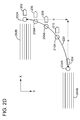
- FIG. 2D which corresponds to Figure 4 of U.S. Patent Application No. 14/902,926 , the entire content of which is incorporated by reference herein).
- This system called StagSeis, includes two streamer vessels 202 and 204 and three source vessels 206, 208 and 210.
- the streamer vessels 202 and 204 are towing corresponding streamer spreads 202B and 204B, and optionally, one or more seismic source arrays 202A and 204A.
- a source array may include one or more sub-arrays and a sub-array may include one or more source elements.
- a source element may be an air gun, a vibratory element, etc.
- a streamer vessel necessarily tows a streamer spread while a source vessel necessarily tows a source array. However, it is possible that the streamer vessel also tows a source array, as illustrated in Figure 2D .
- the sources are staggered both along the inline direction X and the cross-line direction Y.
- the StagSeis configuration may have the sources distributed along a curved line 220.
- line 220 is a straight line, slanted or not relative to the advancing path of the vessels.
- a method for generating a full acquisition path for a marine seismic acquisition system includes receiving survey area information about a survey area (350) to be seismically surveyed; selecting a radius (R) and a length (L) of a lace; selecting an overlap distance (OL) between first and second lanes; generating the full acquisition path by repeating the lace along a first lead line inside the first lane and along a second lead line inside the second lane and replicating the first and second lanes until the entire survey area is covered with laces; and sending the full acquisition path to a streamer vessel for performing the seismic survey.
- a marine acquisition system for collecting seismic data.
- the system includes a first streamer vessel; a source towed by the first streamer vessel and configured to generate seismic waves; a streamer spread towed by the first streamer vessel and configured to collect the seismic data generated by the seismic waves; and a navigation system located on the first streamer vessel and configured to control the first streamer vessel to follow a first full acquisition path over a survey area.
- the first full acquisition path includes plural laces connected to each other, each lace being defined by a radius (R) and a length (L).
- a method for generating a full acquisition path for a seismic survey includes receiving characteristics of a survey area to be survey; and generating the full acquisition path by replicating a lace along overlapping lanes, where the overlapping lanes cover the entire survey area.
- the full acquisition path includes a set of straight lines and a set of coils.
- a new marine seismic survey design (called herein oxoSeis configuration) includes curved and straight lines (known in the art as pre-plot lines) to be followed by at least a streamer vessel when acquiring the seismic data over a given survey area.
- the path geometry evolves in space and in time, by generating specific path patterns (e.g., a lace) that eventually cover the entire survey area. Full coverage of the survey area may be achieved by overlapping the path patterns along different directions.
- the oxoSeis configuration performs in one go both the MAZ and the Coil surveys, with their advantages.
- the oxoSeis configuration will substantially achieve the source-receiver offsets distribution and/or the azimuth distribution that a MAZ survey and a Coil survey would achieve if used sequentially over a same survey area.
- Figure 3A shows a single streamer vessel 302 that tows a source array 306 and a seismic spread 304.
- Source array 306 may include plural sub-arrays, each sub-array including plural source elements.
- a source element may be an air gun, a vibratory source, etc.
- the seismic spread may include one or more streamers, each streamer including at least one seismic sensor.
- a seismic sensor may be a hydrophone, geophone, accelerometer, optical fiber, etc.
- One or more streamers may be multi-component streamers, i.e., they may include two or more different seismic sensors.
- a first parameter is the travel angle (TA) relative to a fixed reference system XY, as illustrated in Figure 3A .
- Figure 3A shows that first path portion 312 of path 310 makes a 180° (or zero) angle with axis X of the reference system. This angle can be different from 180 or zero.
- First path portion 312 is a straight line and has a length L1 and the first path portion extends from connecting points 312A to 312B. Following it, the vessel enters a second path portion 314, which is part of a circle.
- second path portion 314 has a radius R1.
- second path portion 314 is not a full circle.
- the shape of the second path portion is part of an ellipse or parabola, i.e., it is a curved path.
- Second path portion 314 extends from connecting point 312B to connecting point 314B.
- vessel 302 follows a third path portion 316, which is again a straight line path.
- the length of the third path portion 316 is L2.
- the third path portion 316 extends from connecting point 314B to connecting point 316B.
- vessel 302 follows a fourth path portion 318, which is again a curved path.
- fourth path portion 318 is part of a circle having a radius R2 and extends from connecting point 316B to connecting point 318B.
- This pattern (first to forth path portions) shown in Figure 3A which is called a "lace” herein, includes two straight line portions 312 and 316 (substantially perpendicular to each other; however, one skilled in the art would understand that the two straight line portions may have an intersection angle (IA) different from 90°) and two curved portions 314 and 318, connected to each other to form a single path 310.
- Lace 320 is thus characterized by two radiuses R1 and R2, two lengths L1 and L2 and intersection angle IA.
- Lace 320 is the basic pattern that is repeated over the entire survey area as discussed next. Lace 320 extends between two parallel lane lines 330 and 332 that define a lane 321. As will be discussed later, the vessel is instructed to follow lace 320 and then repeat it along lane 321 until the entire lane is covered. Then, as also discussed later, a next lane 321' is covered by the vessel with the same lace 320 or a different lace 322 as illustrated in Figure 3F .
- the parallel lines 330 and 332 may form a given lane angle ⁇ with axis X of the fixed reference system XY. This angle can have any desired value for a given survey.
- lengths L1 and L2 may be identical or different. These lengths may have a value between a few km to tens if not hundreds of kms.
- Radiuses R1 and R2 may have the same value or different values. These radiuses may have a value between a few hundreds of meters to a few km, depending on the length of the streamers.
- first lead line 340 may be a straight line that extends parallel to lane lines 330 and 332.
- Figure 3C shows the lace 320 repeated along first lead line 340 until a border of the survey area 350 is reached while Figure 3D shows the lace 320 being repeated along a second lead line 342, which is opposite in direction and substantially parallel to the first lead line 340.
- Figure 3C also shows lace 320 being repeated along first lead line 340, in an opposite direction, by vessel 302'.
- vessel 302' and vessel 302 follow different paths, made of same lace 320, with one vessel moving along the first lead line 340 while the other vessel moves in an opposite direction of the first lead line.
- the laces (or the path) followed by vessel 302 are shifted relative to the laces (or the path) followed by vessel 302' by a shift S (see Figure 3C ) so that the two vessels' paths do not coincide.
- vessel 302' is the same as vessel 302.
- the vessels are different, they can simultaneously follow the paths shown in Figure 3C .
- the two vessels follow their paths with a time offset.
- the full acquisition path 310 includes straight and curved portions as discussed above. Note that full acquisition path 310 is smooth, i.e., the vessel does not have to make any jumps from one path portion to another portion.
- Figure 3E shows the survey area 350 being entirely being covered by lace 320 replicated along substantially parallel lead lines 340, 342, 344, etc. but also covered for a second time, by vessel 302' and spread 304' along substantially parallel lead lines 340', 342', 344', etc., which are rotated by a rotation angle ⁇ relative to lead lines 340, 342, 344, etc.
- rotation angle ⁇ is about 90.
- Vessel 302' may be the same as vessel 302 or different.
- the lace followed by vessel 302' may have the same radius R' and length L' as the lace followed by vessel 302 or different.
- the full acquisition path of vessel 302' may be identical to path 310 of vessel 302, but rotated with the rotation angle ⁇ , or it may be different.
- laces 320 along lead line 340 and laces 322 along lead line 342 may have different relative positions as illustrated in Figure 3F .
- Figure 3F illustrates a single lace 320 and a single lace 322 for simplicity. The two laces partially overlap. The amount of overlap can change from survey to survey or even from one lead line 340 to the next lead line 342.
- connecting points 312B, 314B, 316B and 318B correspond to connecting portions between the straight line paths 312 and 316 and the curved paths 314 and 318 that form lace 320.
- the same points may be the connecting points for lace 322, as also illustrated in Figure 3F .
- the curved paths 314 and 318 are substantially three quarters of a full circle.
- the straight path portions 312 and 316 have the same length L as the corresponding straight path portions of lace 322.
- the amount of overlap between adjacent laces 320 and 322 can be quantified, for example, by the amount OL that separates lane lines 332 and 330'. More specifically, if lane lines 330 and 332 are considered to define the spatial extension of lace 320 (i.e., these two lines define a lane 321 in which lace 320 is repeated from one side to another side of the survey area) and land lines 330' and 332' are considered to define the spatial extension of lace 322 (i.e., these two lines define another lane 321' in which lace 322 is repeated from the another side to the one side of the survey area), the distance OL defines how much the lanes are overlapped.
- the distance OL is between 3R and 4R. However, for another survey, the distance OL may be smaller than 3R or larger than 4R. In one embodiment, lane line 330' passes through connecting points 312B and 314B.
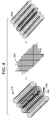
- the full acquisition path 310 illustrated in Figure 3D may be viewed as a superposition of a set of straight and perpendicular lines 360 and a set of coils 362 as illustrated in Figure 4 .
- This oxoSeis configuration can be modified to further improve the source-receiver offset distribution and/or the azimuth distribution.
- lead line 340 also lead lines 342, 344 and so on
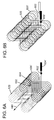
- lead line 540 is shown in Figure 5A as being a straight line
- lead line 540 is shown in Figure 5B . If this is the case, lace 520's orientation changes as the vessel advances along its path.
- FIG. 6A shows two streamer vessels 602 and 602' following similar laces 620 and 620', respectively, both laces following a same lead line 640. Laces 620 and 620' are interleaved as illustrated in the figure. One or more source vessels (vessels that tow only sources) may also be present similar to the StagSeis configuration.
- Figure 6B illustrated in Figure 6B , the two streamer vessels 602 and 602' follow corresponding laces 620 and 620' that are juxtaposed. Again, more than two vessels (e.g., additional streamer and/or source vessels) may be involved in this configuration.
- an inline distance 770 between two vessels 702 and 702' may be controlled to further optimize the offset and/or azimuth distribution.
- the inline distance 770 is the equivalent of a phase parameter when a multi-vessel system is used.
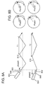
- Figure 8A shows two vessels 802 and 802' towing corresponding streamers 804 and 804', respectively, and corresponding sources 806 and 806'.
- the vessels follow undulating paths 810 and 810' (e.g., a sinusoid) that have corresponding periods T1 and T2.
- the periods may be identical.
- the number of vessels is described by index "i," which is 2 for Figure 8A and 4 for Figure 8B.
- Figure 8B illustrates four vessels that follow circular paths (coil configuration) with different phases.
- Figure 8B i.e., four vessels that follow coil paths. If all the vessels have the same phases as illustrated in Figure 9A (e.g., zero), the corresponding fold map is shown in Figure 9B , and the rose diagram illustrating the offset and azimuth distributions are illustrated in Figure 9C.
- Figure 10A shows the same four vessels having different phases (e.g., 0, T/4, T/2, 3T/4).
- Figure 10B shows the fold map and
- Figure 10C shows the rose diagram illustrating the offset and azimuth distributions. Note that both the fold map and the rose diagrams are substantially different from each other in Figures 9C and 10C , which suggests that the phase has a large impact on them.
- the vessels discussed above may follow straight paths (pre-plot sail lines) or curved paths having amplitudes, periods and phases that may or may not be the same.
- the amplitudes, periods, and phases for the curved paths may be optimized to obtain better azimuth and offset diversity for the recorded data.
- the streamers may include hydrophones, geophones, accelerometers, optical fiber, or a combination of them.
- the streamers may have different lengths and the number of streamers may differ.
- the streamer spreads may be different or the same.
- each vessel it is conventional to tow a source array that includes three sub-arrays.
- Each sub-array includes a float to which individual source elements are attached.
- all the individual source elements may be located at a same or different depth.
- each vessel tows two or more source arrays.
- step 1100 information about the survey area is received. This information may include the length and width of the survey area, its location, ocean conditions at the survey area (e.g., sound speed in water, presence of ocean currents, water temperature, etc.), and/or survey target geological information (e.g., type of target, presence of salt, etc.).
- step 1102 the lace's geometry is selected. For example, the size R of the coils, the length L of the straight lines and the angle between the straight lines may be selected by the survey's operator in this step. This selection is based on the aim of the seismic survey, the required or desired azimuth distribution and/or offset distribution.
- step 1104 the geometry of the full acquisition path 310 is selected so that the propagation of the lace 320 along lead lines 340, 342, etc. covers the entire survey area 350.
- lead lines 340, 342, ... are straight lines or curved, if curved, what kind of curve, the length of these lines, the orientation (i.e., travel angle TA) of these lines relative to a fixed system of reference, and also the orientation (i.e., intersection angle IA) of the straight lines relative to each other, as discussed previously with regard to Figure 3A .
- the overlap distance OL between two lanes 321 and 321' is selected.
- step 1106 the configuration of the acquisition system, i.e., the number of vessels (streamer and source vessels) to cover the survey area is selected.
- the initial direction and azimuth of the vessels may also be selected, as illustrated in Figure 3E .
- the inline distance 770 (or phase) between the vessels and/or whether their laces are juxtaposed or interleaved is selected.
- one or more of the above noted parameters may be optimized to adjust the desired offset distribution and/or azimuth distribution. For example, it is possible to calculate an illumination to be obtained with the acquisition system discussed above and to compare it with a baseline illumination that is desirable for the survey area. If the calculated illumination deviates from the baseline illumination by more than a given value, one or more of the parameters noted in steps 1102, 1104 and 1106 may be adjusted until the calculated illumination is closest to the baseline illumination. Once the closest illumination to the baseline illumination is found, the values of the corresponding parameters for the closest calculated illumination are saved and, if necessary, transmitted in step 1110 to the vessel(s) participating in the seismic survey for implementation.
- step 1112 the vessel(s) acquires the seismic data by following the selected full acquisition path and in step 1114 the collected seismic data is processed to generate an image of the surveyed area. This image is then used by the oil and gas companies to decide where to drill for extracting the underground resources.
- Figure 12 illustrates a method for generating a full acquisition path for a seismic survey.
- the method includes a step 1200 of receiving characteristics of a survey area (350) to be survey, and a step 1202 of generating the full acquisition path by replicating a lace (320) along overlapping lanes (321, 321'), where the overlapping lanes cover the entire survey area.
- the full acquisition path includes a set of straight lines and a set of coils.
- the methods and algorithms discussed above may be implemented in a computing device 1300 as illustrated in Figure 13 .
- the computing device 1300 may be the vessel's navigation system and it may include a processor 1302, a computer, a server, etc. connected through a bus 1304 to a storage device 1306.
- the storage device 1306 may be any type of memory and may store necessary commands and instructions associated with positioning the sources and the streamer spreads as discussed above.
- Also connected to the bus 1304 is an input/output interface 1308 through which the operator may interact with the vessels.
- a communication interface 1310 is also connected to the bus 1304 and is configured to transfer information between the processor 1302 and an outside network, Internet, operator's internal network, etc.
- the communication interface 1310 may be wired or wireless.
- computing device 1300 may include a screen 1312 for displaying various results generated by the algorithms discussed above. For example, the positions of the vessels along various laces may be displayed on the screen 1312.
Landscapes
- Engineering & Computer Science (AREA)
- Life Sciences & Earth Sciences (AREA)
- Physics & Mathematics (AREA)
- Remote Sensing (AREA)
- General Physics & Mathematics (AREA)
- General Life Sciences & Earth Sciences (AREA)
- Geology (AREA)
- Environmental & Geological Engineering (AREA)
- Acoustics & Sound (AREA)
- Oceanography (AREA)
- Geophysics (AREA)
- Combustion & Propulsion (AREA)
- Chemical & Material Sciences (AREA)
- Mechanical Engineering (AREA)
- Ocean & Marine Engineering (AREA)
- Aviation & Aerospace Engineering (AREA)
- Radar, Positioning & Navigation (AREA)
- Automation & Control Theory (AREA)
- Geophysics And Detection Of Objects (AREA)
Applications Claiming Priority (1)
| Application Number | Priority Date | Filing Date | Title |
|---|---|---|---|
| US201562189222P | 2015-07-07 | 2015-07-07 |
Publications (2)
| Publication Number | Publication Date |
|---|---|
| EP3115808A2 true EP3115808A2 (fr) | 2017-01-11 |
| EP3115808A3 EP3115808A3 (fr) | 2017-03-29 |
Family
ID=56404056
Family Applications (1)
| Application Number | Title | Priority Date | Filing Date |
|---|---|---|---|
| EP16305845.6A Withdrawn EP3115808A3 (fr) | 2015-07-07 | 2016-07-05 | Conception pré-segment d'étude sismique marine |
Country Status (2)
| Country | Link |
|---|---|
| US (1) | US9945973B2 (fr) |
| EP (1) | EP3115808A3 (fr) |
Cited By (1)
| Publication number | Priority date | Publication date | Assignee | Title |
|---|---|---|---|---|
| NO20171320A1 (en) * | 2017-08-08 | 2019-02-11 | Polarcus Dmcc | Method and vessel steering module for seismic data acquiring and for routing a vessel, by generating a first straight line from a starting point to an end point and generating offset straight lines |
Families Citing this family (2)
| Publication number | Priority date | Publication date | Assignee | Title |
|---|---|---|---|---|
| US11673628B2 (en) | 2019-04-17 | 2023-06-13 | Pgs Geophysical As | Marine survey source route configuration for multi-azimuth acquisition |
| CN120085371A (zh) * | 2025-05-06 | 2025-06-03 | 中国石油集团东方地球物理勘探有限责任公司 | 一种海洋拖缆螺旋观测采集方法、装置、设备及存储介质 |
Citations (1)
| Publication number | Priority date | Publication date | Assignee | Title |
|---|---|---|---|---|
| US20130188448A1 (en) | 2012-01-24 | 2013-07-25 | Cggveritas Services Sa | Multi-vessel seismic acquisition with undulating navigation lines |
Family Cites Families (12)
| Publication number | Priority date | Publication date | Assignee | Title |
|---|---|---|---|---|
| US7466632B1 (en) | 2004-05-04 | 2008-12-16 | Westerngeco L.L.C. | Method and apparatus for positioning a center of a seismic source |
| US7400552B2 (en) | 2006-01-19 | 2008-07-15 | Westerngeco L.L.C. | Methods and systems for efficiently acquiring towed streamer seismic surveys |
| US8559265B2 (en) | 2007-05-17 | 2013-10-15 | Westerngeco L.L.C. | Methods for efficiently acquiring wide-azimuth towed streamer seismic data |
| US8488409B2 (en) | 2007-05-17 | 2013-07-16 | Westerngeco L.L.C. | Acquiring azimuth rich seismic data in the marine environment using a regular sparse pattern of continuously curved sail lines |
| US8416640B2 (en) * | 2009-04-18 | 2013-04-09 | Global Geophysical Services | Methods for optimizing offset distribution of cross spread 3-D seismic surveys using variable shot line length |
| US8711654B2 (en) | 2009-12-30 | 2014-04-29 | Westerngeco L.L.C. | Random sampling for geophysical acquisitions |
| WO2011080571A2 (fr) * | 2009-12-31 | 2011-07-07 | Geco Technology B.V | Acquisition sismique à l'aide de flûtes marines pleines |
| US8949030B2 (en) | 2011-07-29 | 2015-02-03 | Westerngeco L.L.C. | Attenuating sea-surface ghost wave effects in seismic data |
| US20130028045A1 (en) | 2011-07-29 | 2013-01-31 | Ralf Ferber | Seismic survey designs for attenuating sea-surface ghost wave effects in seismic data |
| US9103942B2 (en) | 2011-10-28 | 2015-08-11 | Westerngeco L.L.C. | Methods and systems for survey designs |
| US20140121977A1 (en) | 2012-11-01 | 2014-05-01 | Pgs Geophysical As | Methods and systems for monitoring a petroleum reservoir |
| WO2015011247A1 (fr) | 2013-07-26 | 2015-01-29 | Cgg Services Sa | Système et procédé d'acquisition sismique utilisant de multiples navires |
-
2016
- 2016-07-05 US US15/202,079 patent/US9945973B2/en not_active Expired - Fee Related
- 2016-07-05 EP EP16305845.6A patent/EP3115808A3/fr not_active Withdrawn
Patent Citations (1)
| Publication number | Priority date | Publication date | Assignee | Title |
|---|---|---|---|---|
| US20130188448A1 (en) | 2012-01-24 | 2013-07-25 | Cggveritas Services Sa | Multi-vessel seismic acquisition with undulating navigation lines |
Cited By (5)
| Publication number | Priority date | Publication date | Assignee | Title |
|---|---|---|---|---|
| NO20171320A1 (en) * | 2017-08-08 | 2019-02-11 | Polarcus Dmcc | Method and vessel steering module for seismic data acquiring and for routing a vessel, by generating a first straight line from a starting point to an end point and generating offset straight lines |
| WO2019031969A1 (fr) * | 2017-08-08 | 2019-02-14 | Polarcus Dmcc | Procédé et module d'orientation de navire pour l'acquisition de données sismiques et pour le guidage d'un navire |
| NO343551B1 (en) * | 2017-08-08 | 2019-04-01 | Polarcus Dmcc | Method and vessel steering module for seismic data acquiring and for routing a vessel, by generating a first straight line from a starting point to an end point and generating offset straight lines |
| GB2582064A (en) * | 2017-08-08 | 2020-09-09 | Polarcus Shipholding As | Method and vessel steering module for seismic data acquiring and for routing a vessel |
| GB2582064B (en) * | 2017-08-08 | 2022-03-02 | Shearwater Invest As | Method and vessel steering module for seismic data acquiring and for routing a vessel |
Also Published As
| Publication number | Publication date |
|---|---|
| US20170090055A1 (en) | 2017-03-30 |
| US9945973B2 (en) | 2018-04-17 |
| EP3115808A3 (fr) | 2017-03-29 |
Similar Documents
| Publication | Publication Date | Title |
|---|---|---|
| US11099287B2 (en) | Seismic data processing | |
| US9958564B2 (en) | Multi-vessel seismic acquisition system and method | |
| US8908471B2 (en) | Method for building velocity models for imaging in multi-azimuth marine seismic surveys | |
| US8949030B2 (en) | Attenuating sea-surface ghost wave effects in seismic data | |
| NO333201B1 (no) | Fremgangsmate for akvisisjon og prosessering av seismiske data | |
| EP3983827B1 (fr) | Acquisition de données sismiques hybrides utilisant, des récepteurs de fond, des flûtes sismiques et des sources remorquées de grandes séparations | |
| US10139511B2 (en) | Staggered source array configuration system and method | |
| AU2012201130B2 (en) | Method and device for alternating depths marine seismic acquisition | |
| CN105960600B (zh) | 在多个地震勘探船之间具有变化相对距离的地震数据获取 | |
| US11604297B2 (en) | Highly-sparse seabed acquisition designs adapted for imaging geological structure and/or monitoring reservoir production | |
| US20200012004A1 (en) | Method and system for seismic data acquisition with front and top sources | |
| EP3341757B1 (fr) | Collecte nodale hybride | |
| US9689999B2 (en) | Seismic imaging using higher-order reflections | |
| US20130028045A1 (en) | Seismic survey designs for attenuating sea-surface ghost wave effects in seismic data | |
| US20160363682A1 (en) | Efficient survey design to in-fill a pre-existing plural vessels seismic survey | |
| US9945973B2 (en) | Marine seismic survey pre-plot design | |
| GB2529038A (en) | Seismic imaging using higher-order reflections |
Legal Events
| Date | Code | Title | Description |
|---|---|---|---|
| PUAI | Public reference made under article 153(3) epc to a published international application that has entered the european phase |
Free format text: ORIGINAL CODE: 0009012 |
|
| STAA | Information on the status of an ep patent application or granted ep patent |
Free format text: STATUS: THE APPLICATION HAS BEEN PUBLISHED |
|
| AK | Designated contracting states |
Kind code of ref document: A2 Designated state(s): AL AT BE BG CH CY CZ DE DK EE ES FI FR GB GR HR HU IE IS IT LI LT LU LV MC MK MT NL NO PL PT RO RS SE SI SK SM TR |
|
| AX | Request for extension of the european patent |
Extension state: BA ME |
|
| PUAL | Search report despatched |
Free format text: ORIGINAL CODE: 0009013 |
|
| AK | Designated contracting states |
Kind code of ref document: A3 Designated state(s): AL AT BE BG CH CY CZ DE DK EE ES FI FR GB GR HR HU IE IS IT LI LT LU LV MC MK MT NL NO PL PT RO RS SE SI SK SM TR |
|
| AX | Request for extension of the european patent |
Extension state: BA ME |
|
| RIC1 | Information provided on ipc code assigned before grant |
Ipc: G01V 1/38 20060101AFI20170221BHEP |
|
| STAA | Information on the status of an ep patent application or granted ep patent |
Free format text: STATUS: REQUEST FOR EXAMINATION WAS MADE |
|
| 17P | Request for examination filed |
Effective date: 20170928 |
|
| RBV | Designated contracting states (corrected) |
Designated state(s): AL AT BE BG CH CY CZ DE DK EE ES FI FR GB GR HR HU IE IS IT LI LT LU LV MC MK MT NL NO PL PT RO RS SE SI SK SM TR |
|
| STAA | Information on the status of an ep patent application or granted ep patent |
Free format text: STATUS: THE APPLICATION IS DEEMED TO BE WITHDRAWN |
|
| 18D | Application deemed to be withdrawn |
Effective date: 20200201 |