EP3116258B1 - Procédé pour rapporter des informations d'état de canal, équipement utilisateur et station de base - Google Patents
Procédé pour rapporter des informations d'état de canal, équipement utilisateur et station de base Download PDFInfo
- Publication number
- EP3116258B1 EP3116258B1 EP14884341.0A EP14884341A EP3116258B1 EP 3116258 B1 EP3116258 B1 EP 3116258B1 EP 14884341 A EP14884341 A EP 14884341A EP 3116258 B1 EP3116258 B1 EP 3116258B1
- Authority
- EP
- European Patent Office
- Prior art keywords
- reference signal
- signal set
- csi
- matrix
- base station
- Prior art date
- Legal status (The legal status is an assumption and is not a legal conclusion. Google has not performed a legal analysis and makes no representation as to the accuracy of the status listed.)
- Not-in-force
Links
Images


Classifications
-
- H—ELECTRICITY
- H04—ELECTRIC COMMUNICATION TECHNIQUE
- H04L—TRANSMISSION OF DIGITAL INFORMATION, e.g. TELEGRAPHIC COMMUNICATION
- H04L5/00—Arrangements affording multiple use of the transmission path
- H04L5/003—Arrangements for allocating sub-channels of the transmission path
- H04L5/0048—Allocation of pilot signals, i.e. of signals known to the receiver
-
- H—ELECTRICITY
- H04—ELECTRIC COMMUNICATION TECHNIQUE
- H04B—TRANSMISSION
- H04B17/00—Monitoring; Testing
- H04B17/30—Monitoring; Testing of propagation channels
- H04B17/309—Measuring or estimating channel quality parameters
-
- H—ELECTRICITY
- H04—ELECTRIC COMMUNICATION TECHNIQUE
- H04B—TRANSMISSION
- H04B7/00—Radio transmission systems, i.e. using radiation field
- H04B7/02—Diversity systems; Multi-antenna system, i.e. transmission or reception using multiple antennas
- H04B7/04—Diversity systems; Multi-antenna system, i.e. transmission or reception using multiple antennas using two or more spaced independent antennas
- H04B7/0413—MIMO systems
- H04B7/0456—Selection of precoding matrices or codebooks, e.g. using matrices antenna weighting
-
- H—ELECTRICITY
- H04—ELECTRIC COMMUNICATION TECHNIQUE
- H04B—TRANSMISSION
- H04B7/00—Radio transmission systems, i.e. using radiation field
- H04B7/02—Diversity systems; Multi-antenna system, i.e. transmission or reception using multiple antennas
- H04B7/04—Diversity systems; Multi-antenna system, i.e. transmission or reception using multiple antennas using two or more spaced independent antennas
- H04B7/06—Diversity systems; Multi-antenna system, i.e. transmission or reception using multiple antennas using two or more spaced independent antennas at the transmitting station
- H04B7/0613—Diversity systems; Multi-antenna system, i.e. transmission or reception using multiple antennas using two or more spaced independent antennas at the transmitting station using simultaneous transmission
- H04B7/0615—Diversity systems; Multi-antenna system, i.e. transmission or reception using multiple antennas using two or more spaced independent antennas at the transmitting station using simultaneous transmission of weighted versions of same signal
- H04B7/0619—Diversity systems; Multi-antenna system, i.e. transmission or reception using multiple antennas using two or more spaced independent antennas at the transmitting station using simultaneous transmission of weighted versions of same signal using feedback from receiving side
- H04B7/0621—Feedback content
- H04B7/0626—Channel coefficients, e.g. channel state information [CSI]
-
- H—ELECTRICITY
- H04—ELECTRIC COMMUNICATION TECHNIQUE
- H04L—TRANSMISSION OF DIGITAL INFORMATION, e.g. TELEGRAPHIC COMMUNICATION
- H04L5/00—Arrangements affording multiple use of the transmission path
- H04L5/003—Arrangements for allocating sub-channels of the transmission path
- H04L5/0048—Allocation of pilot signals, i.e. of signals known to the receiver
- H04L5/0051—Allocation of pilot signals, i.e. of signals known to the receiver of dedicated pilots, i.e. pilots destined for a single user or terminal
-
- H—ELECTRICITY
- H04—ELECTRIC COMMUNICATION TECHNIQUE
- H04L—TRANSMISSION OF DIGITAL INFORMATION, e.g. TELEGRAPHIC COMMUNICATION
- H04L5/00—Arrangements affording multiple use of the transmission path
- H04L5/003—Arrangements for allocating sub-channels of the transmission path
- H04L5/0053—Allocation of signalling, i.e. of overhead other than pilot signals
- H04L5/0057—Physical resource allocation for CQI
-
- H—ELECTRICITY
- H04—ELECTRIC COMMUNICATION TECHNIQUE
- H04W—WIRELESS COMMUNICATION NETWORKS
- H04W24/00—Supervisory, monitoring or testing arrangements
- H04W24/10—Scheduling measurement reports ; Arrangements for measurement reports
-
- H—ELECTRICITY
- H04—ELECTRIC COMMUNICATION TECHNIQUE
- H04B—TRANSMISSION
- H04B17/00—Monitoring; Testing
- H04B17/30—Monitoring; Testing of propagation channels
- H04B17/382—Monitoring; Testing of propagation channels for resource allocation, admission control or handover
-
- H—ELECTRICITY
- H04—ELECTRIC COMMUNICATION TECHNIQUE
- H04L—TRANSMISSION OF DIGITAL INFORMATION, e.g. TELEGRAPHIC COMMUNICATION
- H04L5/00—Arrangements affording multiple use of the transmission path
- H04L5/003—Arrangements for allocating sub-channels of the transmission path
- H04L5/0053—Allocation of signalling, i.e. of overhead other than pilot signals
-
- H—ELECTRICITY
- H04—ELECTRIC COMMUNICATION TECHNIQUE
- H04L—TRANSMISSION OF DIGITAL INFORMATION, e.g. TELEGRAPHIC COMMUNICATION
- H04L5/00—Arrangements affording multiple use of the transmission path
- H04L5/003—Arrangements for allocating sub-channels of the transmission path
- H04L5/0058—Allocation criteria
- H04L5/0064—Rate requirement of the data, e.g. scalable bandwidth, data priority
Definitions
- the present invention relates to the communications field, and in particular, to a method for reporting channel state information, user equipment, and a base station in the communications field.
- a modern communications system widely uses multiple antennas to improve a system capacity and coverage, and improve user experience.
- a Long Term Evolution (LTE” for short) R8 system in the 3rd Generation Partnership Project (3rd Generation Partnership Project, "3GPP” for short) can support four antenna ports, while an LTE R10 system can support eight antenna ports.
- a transmit beam forming (Beam Forming, "BF” for short) or precoding technology can be used to obtain a diversity and array gains.
- MIMO Multiple Input Multiple Output
- Precoding generally requires a transmitter to fully learn channel state information (Channel State Information, "CSI” for short).
- CSI Channel State Information
- a commonly used method is that user equipment quantizes instantaneous CSI and feeds back the instantaneous CSI to a base station.
- CSI information fed back by the existing LTE R8 system may include a rank indicator (Rank Indicator, "RI” for short), a precoding matrix indicator (Precoding Matrix Indicator, "PMI” for short), a channel quality indicator (Channel Quality Indicator, "CQI” for short), and the like.
- the RI and the PMI are used to indicate a serial number of a used layer and a used precoding matrix respectively.
- a set of used precoding matrixes is referred to as a codebook, and each precoding matrix in the set may be referred to as a codeword.
- a 4-antenna codebook in the existing LTE R8 system is designed based on a Householder (Householder) transformation, and a dual-codebook design is further introduced into the LTE R10 system for the eight antennas.
- the foregoing two codebooks are primarily pertinent to an antenna design of a conventional base station, where the conventional base station controls an antenna beam direction in a vertical direction by using a fixed downtilt angle or a remote-electrical-tilt downtilt angle, and only a beam direction in a horizontal direction can be adjusted dynamically by means of precoding or beamforming.
- an active antenna system Active Antenna Systems, "AAS” for short
- AAS Active Antenna Systems
- LTE R12 system that is currently launched and a future LTE R13 system are considering communication performance to be enhanced after an AAS system is introduced.
- an AAS base station further provides freedom in designing the vertical direction of the antenna, which is primarily implemented by a two-directional antenna array in the horizontal and vertical directions of the base station.
- each antenna port in the horizontal direction of the conventional base station can be obtained by weighted combination of multiple array elements in the vertical direction, the conventional base station actually uses only a horizontal one-dimensional array.
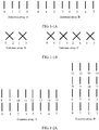
- FIG. 1-1A is a schematic diagram of a uniform linear array (Uniform Linear Array, ULA for short) antenna configuration of a conventional base station
- FIG. 1-1B is a schematic diagram of a cross polarization (Cross Polarization, XPO for short) antenna configuration of the conventional base station
- FIG. 1-1A is a schematic diagram of a uniform linear array (Uniform Linear Array, ULA for short) antenna configuration of a conventional base station
- FIG. 1-1B is a schematic diagram of a cross polarization (Cross Polarization, XPO for short) antenna configuration of the conventional base station
- FIG. 1-2A is a schematic diagram of a uniform linear array antenna configuration of an AAS base station
- FIG. 1-2B is a schematic diagram of a cross polarization antenna configuration of the AAS base station.
- more antenna ports may need to be considered.
- the currently considered quantity of ports may be 8, 16, 32, or 64.
- structures of the antenna arrays may differ. Therefore, a different channel state measurement result may be obtained for an antenna port of a same serial number in a different array structure.
- an antenna array A is a 2-row 8-column uniform linear array
- an antenna array B is a 4-row 4-column uniform linear array.
- the antenna array A and the antenna array B each have 16 antenna ports, the structures of their antenna arrays differ.
- backward compatibility is an important factor to be considered in designing a new LTE R12 system or an LTE system of a higher version.
- the LTE R12 system equipped with an AAS base station can ensure normal operating of UE in LTE R8-R10 systems or can prevent deterioration of operating performance of the UE.
- a new design scheme needs to be proposed about how to measure and report channel state information, so as to improve efficiency or performance of a communications system.
- a method for reporting the channel status information (CSI) from a user equipment in the wireless communication system comprises the steps of: receiving from a base station a first channel status information-reference signal (CSI-RS) on the basis of CSI-RS configuration information with respect to a first domain antenna group having a two-dimensional antenna structure, which is provided from the base station; reporting to the base station a first piece of CSI with respect to the first domain antenna group, which is generated by using the first CSI-RS; receiving from the base station a second CSI-RS, on the basis of CSI-RS configuration information with respect to a second domain antenna group having the two-dimensional antenna structure, which is provided from the base station; and reporting to the base station a second piece of CSI with respect to the second domain antenna group, which is generated by using the second CSI-RS,
- CSI-RS channel status information-reference signal
- Document US 2013/0182594 A1 provides a method for generation of channel state information in a wireless communication system.
- the method includes transmitting, by an evolved Node B (eNB), a first reference signal to a plurality of User Equipments (UEs), receiving channel state information generated based on the first reference signal from the plurality of UEs, selecting candidate UEs to which wireless resources are to be allocated and transmitting second reference signals to the selected candidate UEs, receiving channel state information generated based on the second reference signals from the candidate UEs, and selecting final UEs, to which wireless resources are to be allocated, from the candidate UEs based on the channel state information generated based on the second reference signals, and transmitting control information for data reception to the selected final UEs.
- eNB evolved Node B
- UEs User Equipments
- Document EP 2665203 A1 discloses a mobile station configured to receive transmissions from a two-dimensional array of antennas at a base station.
- a main processor of the mobile station is configured to estimate first and second channel states and determine a co-phasing scalar component for each of multiple groups of antennas in the array based on the first channel state.
- the main processor is configured to generate a matrix X that includes a plurality of column vectors selected from a codebook based on the second channel state, generate a matrix P 1 , wherein the matrix P 1 is a block diagonal matrix having the matrix X for each block diagonal element, and generate a matrix P 2 .
- Embodiments of the present invention provide in a first aspect a method for reporting channel state information with the features of claim 1, and in a second aspect a user equipment with the features of claim 7.
- the invention is defined by the appended claims 1-13. The embodiments that do not fall under the scope of the claims have to be interpreted as examples useful for understanding the invention.
- the receiving a second reference signal set sent by the base station, where the second reference signal set is determined based on the first CSI includes: receiving the second reference signal set sent by the base station, where the second reference signal set is determined based on the first RI included in the first CSI, or the second reference signal set is determined based on the first PMI included in the first CSI and a preset quantity of layers of a precoding matrix, or the second reference signal set is determined based on the first RI and the first PMI included in the first CSI.
- each reference signal included in the first reference signal set corresponds to an antenna in an antenna subarray of the base station
- each reference signal included in the second reference signal set corresponds to an antenna subarray of multiple antenna subarrays included in the base station.
- the first RI is 2 raised to the power of an integer.
- a sending period of the first reference signal set is longer than a sending period of the second reference signal set.
- the sending first CSI to the base station, where the first CSI is determined according to the first reference signal set includes: determining a first precoding matrix from a first codebook according to the first reference signal set; and sending the first CSI to the base station, where the first CSI includes the first rank indicator RI and/or the first precoding matrix indicator PMI, and the first PMI is used to indicate the first precoding matrix, where a precoding matrix included in the first codebook is a discrete Fourier transform DFT matrix, a Hadamard matrix, a Householder matrix, a Kronecker product of two DFT matrixes, a Kronecker product of a DFT matrix and a Hadamard matrix, or a Kronecker product of a DFT matrix and a Householder matrix.
- a precoding matrix included in the first codebook is a discrete Fourier transform DFT matrix, a Hadamard matrix, a Householder matrix, a Kronecker product of two DFT matrixes, a Kronecker product of a DFT matrix and
- the second receiving module is specifically configured to: receive the second reference signal set sent by the base station, where the second reference signal set is determined based on the first RI included in the first CSI, or the second reference signal set is determined based on the first PMI included in the first CSI and a preset quantity of layers of a precoding matrix, or the second reference signal set is determined based on the first RI and the first PMI included in the first CSI.
- each reference signal included in the first reference signal set received by the first receiving module corresponds to an antenna in an antenna subarray of the base station
- each reference signal included in the second reference signal set received by the second receiving module corresponds to an antenna subarray of multiple antenna subarrays included in the base station.
- the first RI is 2 raised to the power of an integer.
- a sending period of the first reference signal set received by the first receiving module is longer than a sending period of the second reference signal set received by the second receiving module.
- the first sending module is specifically configured to: determine a first precoding matrix from a first codebook according to the first reference signal set; and send the first CSI to the base station, where the first CSI includes the first rank indicator RI and/or the first precoding matrix indicator PMI, and the first PMI is used to indicate the first precoding matrix, where a precoding matrix included in the first codebook is a discrete Fourier transform DFT matrix, a Hadamard matrix, a Householder matrix, a Kronecker product of two DFT matrixes, a Kronecker product of a DFT matrix and a Hadamard matrix, or a Kronecker product of a DFT matrix and a Householder matrix.
- a precoding matrix included in the first codebook is a discrete Fourier transform DFT matrix, a Hadamard matrix, a Householder matrix, a Kronecker product of two DFT matrixes, a Kronecker product of a DFT matrix and a Hadamard matrix, or a Kronecker product of a D
- GSM Global System for Mobile Communications
- CDMA Code Division Multiple Access
- WCDMA Wideband Code Division Multiple Access
- GPRS General Packet Radio Service
- LTE Long Term Evolution
- FDD Frequency Division Duplex
- TDD Time Division Duplex
- UDD Universal Mobile Telecommunications System
- UMTS Universal Mobile Telecommunications System
- user equipment may be referred to as a terminal (Terminal), a mobile station (Mobile Station, MS for short), a mobile terminal (Mobile Terminal), and the like.
- the user equipment may communicate with one or more core networks over a radio access network (Radio Access Network, RAN for short).
- RAN Radio Access Network
- the user equipment may be a mobile phone (also referred to as a "cellular" phone) or a computer with a mobile terminal.
- the user equipment may also be a portable, pocket-sized, handheld, computer built-in, or in-vehicle mobile apparatus, which exchanges voice and/or data with the radio access network.
- a base station may be a base transceiver station (Base Transceiver Station, BTS for short) in GSM or CDMA, or may be a NodeB (NodeB, NB for short) in WCDMA, or may be an evolved NodeB (Evolutional Node B, eNB for short) in LTE, which is not limited in the present invention.
- BTS Base Transceiver Station
- NodeB NodeB, NB for short
- WCDMA Wideband Code Division Multiple Access
- eNB evolved NodeB
- LTE Long Term Evolutional Node B
- FIG. 2 is a schematic flowchart of a method 100 for reporting channel state information CSI according to an embodiment of the present invention.
- the method 100 may be executed by user equipment. As shown in FIG. 2 , the method 100 includes:
- the first reference signal set includes at least two reference signals
- the second reference signal set includes at least one reference signal.
- Each reference signal corresponds to one antenna port
- each antenna port may correspond to a physical antenna or may correspond to a virtual antenna.
- the virtual antenna may be a weighted combination of multiple physical antennas.
- the user equipment may measure and report channel state information between the user equipment and the antenna port according to the reference signal corresponding to the antenna port.
- a reference signal is generally classified into two types: one type of reference signal is used to measure a channel state or channel quality to implement scheduling; the other type of reference signal is used to perform coherent demodulation on a received signal that includes control information or data information.
- a reference signal that is used for coherent demodulation is referred to as a demodulation reference signal (Demodulation Reference Signals, "DMRS” for short), and this reference signal is also referred to as a UE-specific reference signal (UE-specific reference signal).
- DMRS Demodulation Reference Signals
- UE-specific reference signal UE-specific reference signal
- a reference signal that is used to measure channel state information is referred to as a channel state information reference signal (Channel State Information-Reference Signal, "CSI-RS” for short).
- CSI-RS Channel State Information-Reference Signal
- the DMRS is sent together with a physical downlink shared channel (Physical Downlink Shared Channel, "PDSCH” for short), and is used for channel estimation in PDSCH demodulation.
- the CSI-RS is used by the user equipment in the LTE R10 system to measure a channel state, and is especially used for a multi-antenna transmission scenario.
- a rank indicator (Rank Indicator, "RI” for short)
- a precoding matrix indicator Precoding Matrix Indicator, "PMI” for short
- CQI Channel Quality Indicator
- a cell-specific reference signal may be used by the UE for channel estimation, so as to demodulate a downlink control channel (Physical Downlink Control Channel, "PDCCH” for short) and other common channels, where the reference signal is inherited from an LTE R8/9 system.
- the CRS is further used to measure channel state information and demodulate a data channel.
- the DMRS supports a maximum of 8 antenna ports, and a quantity of DMRS antenna ports used by each UE is notified to the UE by using downlink control information (Downlink Control Information, "DCI" for short).
- DCI Downlink Control Information
- the CSI-RS supports a maximum of 8 antenna ports, for example, a quantity of antenna ports may be 1, 2, 4, or 8.
- a CRS supports a maximum of 4 antenna ports, for example, a quantity of antenna ports may be 1, 2, or 4.
- the CSI-RS has a lower frequency density in order to support a same quantity of antenna ports, and therefore, has lower overheads.
- user equipment may receive a first reference signal set sent by a base station, and determine first CSI according to the first reference signal set and send the first CSI to the base station. Because the first CSI provides preliminary information of a channel state between the base station and the user equipment, the base station can further determine a second reference signal set of the user equipment based on the preliminary information of the channel state. Therefore, the user equipment can obtain second CSI more efficiently or more precisely according to the second reference signal set, thereby enhancing system efficiency or performance.
- the first reference signal set may correspond to an antenna subset of an antenna set configured for the base station.
- Each reference signal in the first reference signal set may correspond to one antenna in the antenna subset, where the antenna subset may be far smaller than the antenna set.
- the antenna subset has relatively strong spatial correlation or the antenna subset has a coarse-grained spatial resolution.
- the user equipment may obtain the first CSI according to the first reference signal set.
- the first CSI may include the first RI and/or the first PMI.
- the first RI can reflect spatial correlation information of a channel between the base station and the user equipment
- the first PMI can reflect spatial resolution information of the channel between the base station and the user equipment. Therefore, the second reference signal set may be determined based on the preliminary information (including the spatial correlation information and/or the spatial resolution information) provided in the first CSI, and further, the user equipment can obtain the second CSI more efficiently or more precisely based on the second reference signal set.
- the AAS has been widely deployed and applied in practice.
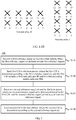
- the following uses a cross polarization antenna array configuration shown in FIG. 3A and FIG. 3B as an example and uses a uniform linear array antenna configuration shown in FIG. 4A and FIG. 4B as an example to elaborate the method for reporting channel state information according to this embodiment of the present invention.
- This embodiment of the present invention is described by using merely an AAS antenna configuration as an example.
- the present invention is not limited thereto, and the technical solution in this embodiment of the present invention is also applicable to an antenna configuration of other systems.
- FIG. 3A shows a dual-polarized antenna array that includes 64 antennas, where the antenna array may be divided into two co-polarized antenna arrays: a co-polarized antenna array A and a co-polarized antenna array B shown in FIG. 3A .
- the two co-polarized antenna arrays are formed by +45° polarized antennas and -45° polarized antennas respectively.
- the co-polarized antenna array A may be further divided into 4 same antenna subarrays: co-polarized antenna subarrays a0, a1, a2, and a3 shown in FIG. 3A .
- the co-polarized antenna array B may be further divided into 4 same antenna subarrays b0, b1, b2, and b3.
- Each of the antenna subarrays includes 8 antennas. It should be noted that the co-polarized antenna subarrays a0, a1, a2, and a3 are in same positions as the antenna subarrays b0, b1, b2, and b3 respectively. That is, the dual-polarized antenna array may be divided into a total of 8 antenna subarrays.
- the first reference signal set may be transmitted on only one of the antenna subarrays.
- Each reference signal included in the first reference signal set corresponds to an antenna in an antenna subarray of the base station.
- the first reference signal set may be transmitted on only the co-polarized antenna subarray a0. That is, the first reference signal set may include 8 reference signals.
- Each of the reference signals is transmitted on one antenna in the co-polarized antenna subarray a0.
- the user equipment UE can determine a first precoding matrix from a first codebook by receiving each reference signal in the first reference signal set transmitted by the base station on the co-polarized antenna subarray a0, where the first precoding matrix is a matrix in an 8-antenna precoding codebook.
- the user equipment may, by sending the first CSI to the base station, indicate the first precoding matrix determined by the user equipment, where the first CSI may include the first rank indicator RI and/or the first PMI.
- the first PMI may be used to indicate the first precoding matrix
- the first RI may be used to indicate a quantity of columns of the first precoding matrix, that is, a quantity of layers of the first precoding matrix.
- the first CSI may further include other information such as a first channel quality indicator CQI.
- the first rank RI of the first precoding matrix may also be a size of a maximal linearly independent group formed by all column vector sets of the first precoding matrix. It should also be understood that due to spatial correlation between antennas in an antenna subarray, the first RI is generally far smaller than a quantity S S of antennas included in the co-polarized antenna subarray, where S S is the size of the co-polarized antenna subarray.
- the first precoding matrix determined by the user equipment by measuring the first reference signal set includes spatial directivity information of the channel between the base station and the user equipment. Therefore, the first CSI provided by the user equipment for the base station provides (by using the spatial directivity information) the base station with a coverage area of the second reference signal set sent to the user equipment.
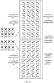
- the base station may precode each antenna subarray (that is, the co-polarized antenna subarrays a0, a1, a2, a3, b0, b1, b2, and b3), so as to obtain the antenna port corresponding to each antenna subarray.
- the precoding matrix used by the base station for precoding each antenna subarray may be consistent with the first precoding matrix determined according to the first CSI sent by the user equipment, or may be a variation of the first precoding matrix determined according to the first CSI sent by the user equipment, for example, obtained by performing symmetric amplitude weighting on each column vector in the first precoding matrix.
- Each antenna port is a combination obtained by precoding a corresponding antenna subarray by using the first precoding matrix. For example, as shown in FIG.
- antenna ports Pa0, Pa1, Pa2, and Pa3 are antenna ports obtained by precoding the antenna subarrays a0, a1, a2, and a3 respectively; antenna ports Pb0, Pb1, Pb2, and Pb3 are antenna ports obtained by precoding the antenna subarrays b0, b1, b2, and b3 respectively.
- Each of the antenna ports is a combination obtained by precoding a corresponding antenna subarray by using a column of the first precoding matrix.
- the second reference signal set used by the user equipment and determined by the base station may include RI 1 *N S reference signals.
- the reference signals may be transmitted on the antenna ports Pa0, Pa1, Pa2, and Pa3 and the antenna ports Pb0, Pb1, Pb2, and Pb3 respectively.
- the user equipment may calculate and report the second channel state information CSI, where the second CSI may include at least one of a second channel quality indicator CQI, a second precoding matrix indicator PMI, or a second rank indicator RI.
- the uniform linear antenna array includes 64 antennas, and the array may be divided into two co-polarized antenna arrays: a co-polarized antenna array C and a co-polarized antenna array D shown in FIG. 4A . Both of the two co-polarized antenna arrays are formed by vertically polarized or 90° polarized antennas.
- the co-polarized antenna array C may be further divided into 4 same antenna subarrays: co-polarized antenna subarrays c0, c1, c2, and c3 shown in FIG. 4A .
- the co-polarized antenna array D may be further divided into 4 same antenna subarrays d0, d1, d2, and d3. Each of the antenna subarrays includes 8 antennas.
- the co-polarized antenna subarrays c0, c1, c2, and c3 are in different positions than the antenna subarrays d0, d1, d2, and d3 respectively. That is, the dual-polarized antenna array may be divided into a total of 8 antenna subarrays.
- the first reference signal set may be transmitted on only one of the antenna subarrays, for example, transmitted on the co-polarized antenna subarray c0. That is, the first reference signal set may include 8 reference signals. Each of the reference signals is transmitted on one antenna in the co-polarized antenna subarray c0. Therefore, the user equipment UE can determine a first precoding matrix from a first codebook by receiving each reference signal in the first reference signal set transmitted by the base station on the co-polarized antenna subarray c0, where the first precoding matrix is a matrix in an 8-antenna precoding codebook.
- the user equipment may, by sending the first CSI to the base station, indicate the first precoding matrix determined by the user equipment, where the first CSI may include the first rank indicator RI and/or the first PMI. Further, the first CSI may further include other information such as a first channel quality indicator CQI. It should be understood that due to spatial correlation between antennas in an antenna subarray, the first RI is generally far smaller than a quantity S S of antennas included in the co-polarized antenna subarray, where S S is the size of the co-polarized antenna subarray.
- the precoding matrix acquired by the user equipment by measuring the first reference signal set sent by the antenna subarray includes spatial directivity information of the channel between the base station and the user equipment. Therefore, the CSI information provided by the user equipment for the base station provides the base station with a coverage area of the second reference signal set sent to the user equipment.
- the base station may precode each antenna subarray (including the co-polarized antenna subarrays c0, c1, c2, c3, and the co-polarized antenna subarrays d0, d1, d2, and b3), so as to obtain the antenna port corresponding to each antenna subarray.
- the precoding matrix used for precoding may be consistent with the first precoding matrix determined according to the first CSI sent by the user equipment, or the precoding matrix used for precoding is a variation of the first precoding matrix determined according to the first CSI sent by the user equipment, for example, obtained by performing symmetric amplitude weighting on each column vector in the first precoding matrix.
- Each antenna port is a combination obtained by precoding a corresponding antenna subarray by using the first precoding matrix. For example, as shown in FIG.
- the antenna ports Pc0, Pc1, Pc2, and Pc3 are antenna ports obtained by precoding the antenna subarrays c0, c1, c2, and c3 respectively; the antenna ports Pb0, Pb1, Pb2, and Pb3 are antenna ports obtained by precoding the antenna subarrays b0, b1, b2, and b3 respectively.
- Each of the antenna ports is a combination obtained by precoding a corresponding antenna subarray by using a column of the first precoding matrix.
- the second reference signal set used by the user equipment and determined by the base station includes RI 1 *N S reference signals.
- the reference signals may be transmitted on the antenna ports Pc0, Pc1, Pc2, and Pc3 and the antenna ports Pd0, Pd1, Pd2, and Pd3 respectively.
- the user equipment may determine and report the second channel state information CSI, where the second CSI may include at least one of a second channel quality indicator CQI, a second precoding matrix indicator PMI, or a second rank indicator RI.
- the user equipment measures reference signals included in the first reference signal set and the second reference signal set that are received, and feeds back the channel state information, where the first reference signal set uses S S reference signal ports and the second reference signal set uses RI 1 *N S reference signal ports.
- the system uses a total of S S +RI 1 *N S reference signal ports; and when one reference signal set is a subset of the other reference signal set, the system uses a total of max(S S , RI 1 *N S ) reference signal ports, where max(S S , RI 1 *N S ) denotes a larger value between S S and RI 1 *N S .
- the user equipment measures reference signals included in the first reference signal set and the second reference signal set that are received, and feeds back the first CSI and the second CSI.
- the first CSI is obtained based on S S reference signal ports used by the first reference signal set
- the second CSI is obtained based on RI 1 *N S reference signal ports used by the second reference signal set, where S S , RI 1 *N S , and S S +RI 1 *N S are all less than the total quantity N T of antenna ports.
- S S , RI 1 *N S , and S S +RI 1 *N S are all less than the total quantity N T of antenna ports.
- using the same feedback overheads can greatly enhance CSI feedback precision of the S S or S S +RI 1 *N S antenna ports.
- the first CSI includes the first PMI
- feedback precision of the second CSI can be further enhanced based on the spatial resolution information provided by the first reference signal set.
- complexity of implementing CSI measurement of the S S or S S +RI 1 *N S antenna ports is generally far less than complexity of implementing CSI measurement of the N T antenna ports, and therefore, system performance can be improved effectively.
- this embodiment of the present invention is described by using merely the antenna array structure shown in FIG. 3A or FIG. 4A as an example.
- the present invention is not limited thereto, and the method in this embodiment of the present invention is also applicable to other antenna array structures such as an alternating polarization (alternating polarization) antenna array.
- the foregoing division of the antenna array is merely an example, and the antenna array may also be divided in other manners, for example, divided into 4 or 16 antenna subarrays. This embodiment of the present invention is still applicable to, but is not limited to, the foregoing example.
- user equipment acquires first CSI and second CSI respectively according to a first reference signal set and a second reference signal set that are sent by a base station, where the second reference signal set is obtained according to the first CSI. Therefore, spatial correlation of an antenna port corresponding to the first reference signal set can be fully utilized, reference signal overheads of the first reference signal set and the second reference signal set are far smaller than antenna overheads of transmitting reference signals or data, and system efficiency can be improved effectively.
- channel state information measurement is implemented by measuring the first CSI and the second CSI. The first CSI is obtained based on the first reference signal set, and the second CSI is obtained based on the second reference signal set.
- a quantity of antenna ports corresponding to the first reference signal set and the second reference signal set is far smaller than a quantity of antennas that actually transmit the reference signals or data.
- the user equipment On the basis of spatial resolution provided by the first reference signal, the user equipment further measures channel state information CSI by using the second reference signal set, thereby enhancing CSI feedback precision, effectively reducing channel state information measurement complexity of the user equipment, and effectively improving system performance.
- each reference signal included in the first reference signal set corresponds to an antenna in an antenna subarray of the base station
- each reference signal included in the second reference signal set corresponds to an antenna subarray of multiple antenna subarrays included in the base station
- the first reference signal set may be transmitted on only the co-polarized antenna subarray a0 or c0.
- the 8 reference signals included in the first reference signal set are transmitted on one antenna in the co-polarized antenna subarray a0 or c0. That is, the first reference signal set corresponds to an antenna subarray a0 or c0.
- Each reference signal included in the first reference signal set corresponds to one antenna in an antenna subarray a0 of the base station, or corresponds to one antenna in an antenna subarray c0 of the base station.
- the quantity of reference signals included in the first reference signal set is equal to the quantity of antennas in the antenna subarray.
- the second reference signal set includes RI 1 *N S reference signals.
- Each reference signal is transmitted on an antenna subarray of the 8 antenna subarrays a0, a1, a2, a3, b0, b1, b2, and b3. That is, each reference signal included in the second reference signal set corresponds to an antenna subarray of multiple antenna subarrays included in the base station.
- each reference signal corresponds to the antenna subarray a0, a1, a2, a3, b0, b1, b2, or b3, where the quantity of reference signals included in the second reference signal set is equal to the quantity of antenna subarrays.
- the size of the first reference signal set may also be the same as the size of the second reference signal set.
- the first reference signal set and the second reference signal set occupy a same time-frequency resource in a resource block, or a time-frequency resource used by one of the two reference signal sets is a subset of a time-frequency resource used by the other reference signal set; however, the present invention is not limited thereto.
- spatial correlation of an antenna port corresponding to a first reference signal set can be fully utilized, so that reference signal overheads of a first reference signal set and a second reference signal set are far smaller than antenna overheads of transmitting reference signals or data, and system efficiency can be improved effectively.
- user equipment On the basis of spatial resolution provided by a first reference signal, user equipment further measures channel state information CSI by using a second reference signal set, thereby enhancing CSI feedback precision and effectively reducing channel state information measurement complexity of the user equipment.
- the user equipment receives the first reference signal set sent by the base station.
- the user equipment receives the first reference signal set transmitted by the base station on the antenna subarray a0 or c0.
- Each reference signal included in the first reference signal set corresponds to an antenna in an antenna subarray of the base station.
- the sending, by the user equipment, first channel state information CSI to the base station includes: determining, by the user equipment, a first precoding matrix from a first codebook according to the first reference signal set, and sending the first channel state information CSI to the base station, where the first CSI may include the first RI or include the first PMI, and may include the first RI and the first PMI, and the first PMI is used to indicate the first precoding matrix. Further, the first CSI may further include a first CQI and the like, and the present invention is not limited thereto.
- the user equipment performs channel estimation based on the reference signal included in the first reference signal set; and may select the first precoding matrix from the first codebook according to the channel estimation and a predefined criterion such as a channel capacity maximization criterion or a throughput maximization criterion.
- a predefined criterion such as a channel capacity maximization criterion or a throughput maximization criterion.
- the precoding matrix may be selected in multiple ways or based on multiple predefined criteria, which, for brevity, are not elaborated herein.
- the user equipment may receive the second reference signal set sent by the base station, where the second reference signal set is determined based on the first CSI.
- the receiving a second reference signal set sent by the base station, where the second reference signal set is determined based on the first CSI includes: receiving the second reference signal set sent by the base station, where the second reference signal set is determined based on the first RI included in the first CSI, or the second reference signal set is determined based on the first PMI included in the first CSI and a preset quantity of layers of a precoding matrix, or the second reference signal set is determined based on the first RI and the first PMI included in the first CSI.
- the first CSI may include only the first rank indicator RI, and the first RI is used to indicate a rank (Rank) of the first precoding matrix.
- the second reference signal set may be determined according to the rank of the first precoding matrix.
- the first RI may be further used to indicate a quantity of layers of the first precoding matrix.
- the quantity of layers of the first precoding matrix may be equal to a quantity of columns of the first precoding matrix, or may be a size of a maximal linearly independent subset formed by all column vector sets of the first precoding matrix.
- the first RI or the preset quantity of layers of the precoding matrix is 2 raised to the power of an integer.
- the first RI or the preset quantity of layers of the precoding matrix is 1, 2, 4, or 8 or the like.
- the base station determines the second reference signal set according to the first RI included in the first CSI and a correspondence between the RI and the reference signal set. Specifically, for example, the base station determines the second reference signal set from at least two candidate reference signal sets according to a correspondence table between the RI and the reference signal set shown in Table 1 or Table 2, where RI 1 denotes the first RI.
- the first CSI may include only the first PMI and does not include the first RI.
- the second reference signal set may be determined according to the first PMI included in the first CSI and the preset quantity of layers of the precoding matrix, where the preset quantity of layers of the precoding matrix may be indicated by the predefined first RI.
- the quantity, of layers of the precoding matrix, indicated by the predefined first RI is smaller than the size of the first reference signal set.
- the size of the first reference signal set may be the quantity of reference signal ports in the first reference signal set or the quantity of antenna ports corresponding to the first reference signal set.
- the quantity of layers of the first precoding matrix is predefined. That is, the quantity of layers of the first precoding matrix is equal to the value of the predefined first RI.
- the size of the second reference signal set is an integer multiple of the quantity of layers of the first precoding matrix, or an integer multiple of the predefined first RI; or the quantity of antenna ports corresponding to the second reference signal set is an integer multiple of the quantity of layers of the first precoding matrix, or an integer multiple of the predefined first RI.
- the value of the predefined first RI is L
- the quantity of layers of the first precoding matrix is L
- the value of the predefined first RI may be determined according to the size of the first reference signal set or the quantity of antenna ports corresponding to the first reference signal set.
- the value of the predefined first RI or the size of the first reference signal set is notified to the user equipment UE by using a broadcast channel or dedicated signaling.
- the first CSI when the first CSI includes only the first PMI, the first RI does not need to be fed back, thereby further reducing feedback overheads effectively.
- the first CSI may include the first PMI and the first RI.
- the second reference signal set is determined according to the first RI or the first PMI included in the first CSI, or may be determined according to both the first RI and the first PMI included in the first CSI, and the present invention is not limited thereto.
- the base station determines the second reference signal set according to the first RI and the first PMI included in the first CSI and a correspondence between the RI and PMI and the reference signal set.
- the base station determines the second reference signal set according to the first PMI included in the first CSI, a predefined first RI, and the correspondence between the RI and PMI and the reference signal set.
- the base station may determine the second reference signal set from at least two candidate reference signal sets according to a correspondence table between the first RI and first PMI and the second reference signal set shown in Table 3 or Table 4, where RI 1 denotes the first RI and PMI 1 denotes the first PMI.
- a resource used by each antenna port may be notified by the base station to the UE by using higher layer signaling.
- a resource used by an antenna port x-x+7, x-x+15, x-x+23, or x-x+31 may be configured by an eNB for the UE by using higher layer signaling.
- a sending period of the first reference signal set is longer than a sending period of the second reference signal set.
- a period of sending the first reference signal set by the base station is longer than a period of sending the second reference signal set. Because an antenna port used for measurement in the first reference signal set has stronger space or time or frequency correlation than an antenna port corresponding to the second reference signal set, and the change of a channel state thereof is relatively slow, a time interval or span of sending the first reference signal set may be longer, thereby further reducing overheads of a time-frequency resource occupied for sending the reference signal set.
- the first CSI has a longer reporting period than the second CSI.
- the reporting period of the first CSI is N times the reporting period of the second CSI, where N is a positive integer.
- the precoding matrix included in the first codebook used by the user equipment for determining the first precoding matrix is a precoding matrix in a 2-antenna codebook, 4-antenna codebook, or 8-antenna codebook in an LTE R10 system, or is a precoding matrix in a 2-antenna codebook, 4-antenna codebook, or 8-antenna codebook in an LTE R12 system.
- the precoding matrix included in the first codebook is a discrete Fourier transform (Discrete Fourier Transform, DFT for short) matrix, a Hadamard (Hadamard) matrix, a Householder (Householder) matrix, a Kronecker (Kronecker) product of two DFT matrixes, a Kronecker product of a DFT matrix and a Hadamard matrix, or a Kronecker product of a DFT matrix and a Householder matrix.
- DFT discrete Fourier Transform
- the precoding matrix in the first codebook may be prestored on the user equipment side or on the base station side, or may be obtained by calculation according to a structure of the precoding matrix, for example, obtained by calculation according to a relationship between the first precoding matrix indicator and the precoding matrix, which, however, is not limited by this embodiment of the present invention.
- the user equipment sends the second CSI to the base station, where the second CSI is determined according to the second reference signal set.
- the second CSI includes the second channel quality indicator CQI.
- the second CQI may be calculated based on a transmit diversity transmission scheme.
- the transmit diversity scheme may be space frequency block coding (Space Frequency Block Coding, "SFBC” for short), space time block coding (Space Time Block Coding, "STBC” for short), or frequency switch transmit diversity (Frequency Switch Transmit Diversity, "FSTD” for short), or the like.
- the second CQI may also be calculated based on an open loop multiple input multiple output (Multiple Input Multiple Output, "MIMO” for short) scheme.
- the open loop MIMO scheme may be a precoding scheme that is based on great-delay cyclic delay diversity and defined in the LTE R8 system.
- the sending second CSI to the base station, where the second CSI is determined according to the second reference signal set includes:
- the precoding matrix included in the second codebook is a precoding matrix in a 2-antenna codebook, 4-antenna codebook, or 8-antenna codebook in an LTE R10 system, or is a precoding matrix in a 2-antenna codebook, 4-antenna codebook, or 8-antenna codebook in an LTE R12 system.
- the precoding matrix included in the second codebook is a discrete Fourier transform DTF matrix, a Hadamard matrix, a Householder matrix, a Kronecker product of two DFT matrixes, a Kronecker product of a DFT matrix and a Hadamard matrix, or a Kronecker product of a DFT matrix and a Householder matrix.
- a precoding matrix W included in the second codebook is a product of two matrixes W 1 and W 2 , where the matrix W 1 is a block diagonal matrix.
- the block diagonal matrix includes at least one block matrix X , and each block matrix X is a Kronecker product of two matrixes C and D .
- y i , k T in the k th column y k of the matrix W 2 may be used to select a column in X i as an antenna port group for precoding, where the antenna port group is generated by using the first precoding matrix, where e j ⁇ i,k may be used to perform phase alignment on the precoding of different antenna port groups generated by using the first precoding matrix, so as to obtain a combined gain and greatly increase a signal to interference plus noise ratio (Signal to Interference plus Noise Ratio, "SINR" for short) of a corresponding layer. Therefore, CSI feedback is performed by using the precoding matrix structure, and structure characteristics of the generated antenna array can be used to improve precision of the CSI feedback and effectively improve a system throughput or spectrum efficiency.
- SINR Signal to Interference plus Noise Ratio
- the phase difference ⁇ ⁇ is a real number. Specifically, the value of ⁇ ⁇ may be 0, ⁇ ⁇ 64 , ⁇ ⁇ 32 , ⁇ ⁇ 16 , ⁇ ⁇ 8 , ⁇ ⁇ 4 , ⁇ ⁇ 2 , ⁇ , or the like.
- a i a 0 a 1 ⁇ a N a ⁇ 1
- B i b 0 b 1 ⁇ b N b ⁇ 1
- N f is a quantity of DFT vectors.
- N g is a quantity of column vectors of the Householder (Householder) matrix G
- N h is a quantity of column vectors of the Hadamard (Hadamard) matrix H N h
- the vector b in (11') or (11") is b ⁇ f 0 , f 1 ,..., f N f -1 ⁇ , b ⁇ g 0 , g 1 ,..., g N g -1 ⁇ or b ⁇ h 0 , h 1 ,..., h N h -1 ⁇ .
- the matrix A i or the matrix B i may also be a precoding matrix in a 2-antenna codebook or 4-antenna codebook in the LTE R8 system, or a precoding matrix in an 8-antenna codebook in the LTE R10 system, or a precoding matrix in a 4-antenna codebook in the LTE R12 system.
- either of the matrix A i and the matrix B i may be 1.
- the phase difference ⁇ ⁇ k is a real number. Specifically, the value of ⁇ ⁇ k may be 0, ⁇ ⁇ 64 , ⁇ ⁇ 32 , ⁇ ⁇ 16 , ⁇ ⁇ 8 , ⁇ ⁇ 4 , ⁇ ⁇ 2 , ⁇ , or the like.
- the phase difference ⁇ ⁇ k is a real number. Specifically, the value of ⁇ ⁇ k may be 0, ⁇ ⁇ 64 , ⁇ ⁇ 32 , ⁇ ⁇ 16 , ⁇ ⁇ 8 , ⁇ ⁇ 4 , ⁇ ⁇ 2 , ⁇ , or the like.
- X 2 X 0
- X 3 X 1 .
- ⁇ 3 ⁇ 1 .
- the matrix W 2 may be: W 2 ⁇ 1 2 Y e j ⁇ 1,1 Y Y e j ⁇ 1,1 Y , 1 2 Y e j ⁇ 1,1 Y jY e j ⁇ 1,1 Y , 1 2 Y e j ⁇ 1,1 Y ⁇ Y ⁇ e j ⁇ 1,1 Y , 1 2 Y e j ⁇ 1,1 Y ⁇ Y ⁇ e j ⁇ 1,1 Y , 1 2 Y e j ⁇ 1,1 Y ⁇ jY ⁇ j e j ⁇ 1,1 Y Y ⁇ e ⁇ 1 , e ⁇ 2 , e ⁇ 3 , e ⁇ 4
- ⁇ n , n 1,2,3,4 denotes a 4x1 selection vector, and among its elements, the n th element is 1, and all remaining elements are 0.
- ⁇ 1,1 is a real number, and its value maybe, for example, 0, ⁇ ⁇ 64 , ⁇ ⁇ 32 , ⁇ ⁇ 16 , ⁇ ⁇ 8 , ⁇ ⁇ 4 , ⁇ ⁇ 2 , or ⁇ .
- the matrix W 2 may be: W 2 ⁇ 1 2 2 Y 1 Y 2 e j ⁇ 1,1 Y 1 e j ⁇ 2 Y 2 Y 1 ⁇ Y 2 e j ⁇ 1,1 Y 1 ⁇ e j ⁇ 1,2 Y 2 , 1 2 2 Y 1 Y 2 e j ⁇ 1,1 Y 1 e j ⁇ 1,2 j Y 2 j Y 1 ⁇ j Y 2 j e j ⁇ 1,1 Y 1 ⁇ j e j ⁇ 1,2 Y 2 Y 1 , Y 2 ⁇ e ⁇ 1 , e ⁇ 1 , e ⁇ 2 , e ⁇ 2 , e ⁇ 3 , e ⁇ 3 , e ⁇ 4 , e ⁇ 4 , e ⁇ 4 , e ⁇ 1 , e ⁇ 2 , e ⁇ 2 , e ⁇ 3 , e ⁇ 1
- ⁇ 1,1 and ⁇ 1,2 are real numbers, and the value of ⁇ 1,1 or ⁇ 1,2 may be 0, ⁇ ⁇ 64 , ⁇ ⁇ 32 , ⁇ ⁇ 16 , ⁇ ⁇ 8 , ⁇ ⁇ 4 , ⁇ ⁇ 2 , ⁇ , and so on.
- the determining a second precoding matrix from a second codebook according to the second reference signal set includes: selecting a second precoding matrix from a codebook subset based on the second reference signal set.
- the codebook subset may be predefined; or may be reported by the UE to the eNB, and then determined by the base station eNB based on the reporting of the UE and notified to the UE; or may be a codebook subset determined and reported by the UE, for example, a recently reported codebook subset. Therefore, feedback overheads and implementation complexity can be further reduced.
- the codebook subset may include a subset of the matrix W 1 or matrix A i or matrix B i or matrix W 2 .
- all codebook subsets have a same subset of the matrix W 1 or matrix A i or matrix B i or matrix W 2 . Therefore, the codebook subsets overlap each other, which can address an edge effect of channel state information quantization.
- the block matrixes X i and X j , i ⁇ j may be unequal or equal. If X i and X j , i ⁇ j are equal, the equal matrixes X i and X j , i ⁇ j may appear in pairs, which can further reduce feedback overheads.
- each matrix may be further multiplied by a scaling factor to implement power normalization or power balance.
- the method 100 further includes:
- the second CSI may be the second RI and/or the second PMI.
- the precoding matrix in the first codebook may be prestored on the user equipment side or on the base station side, or may be obtained by calculation according to a structure of the precoding matrix, for example, obtained by calculation according to a relationship between the first precoding matrix indicator and the precoding matrix, which, however, is not limited by this embodiment of the present invention.
- the precoding matrix structure in the codebook related to each process described above is not limited to being used for two or more CSI measurement processes in the method.
- the precoding matrix structure mentioned in (67) to (70) may be used for the third CSI measurement and reporting process described above, or used for a CSI measurement process based on a single reference signal set.
- the CSI measurement process is similar to a CSI measurement process based on a CRS in the LTE R8 system or based on a CSI-RS in the LTE R8 system, which is not further described in detail herein.
- a scalar is a special case of a vector
- vector is a special case of a matrix.
- the size of the first reference signal set may also be the same as the size of the second reference signal set.
- the first reference signal set and the second reference signal set occupy a same time-frequency resource in a resource block, or a time-frequency resource used by one of the two reference signal sets is a subset of a time-frequency resource used by the other reference signal set; however, the present invention is not limited thereto.
- the first reference signal set and the second reference signal set may use a cell-specific (Cell specific) reference signal CRS or a channel state information reference signal CSI-RS in an LTE system, and the first CSI and the second CSI may be based on a codebook based on the LTE R8 or R10 or R12. In this way, backward compatibility of the system can be kept.
- Cell specific Cell specific
- CSI-RS channel state information reference signal
- a value of a sequence number in the foregoing processes does not indicate an execution sequence, and an execution sequence of each process is determined by its function and internal logic, which shall not constitute any limitation to an implementation process of an embodiment of the present invention.
- user equipment acquires first CSI and second CSI respectively according to a first reference signal set and a second reference signal set that are sent by a base station, where the second reference signal set used by the user equipment is obtained according to a first rank indicator RI and/or a first PMI in the first CSI. Therefore, spatial correlation of an antenna port corresponding to the first reference signal set can be fully utilized, reference signal overheads of the first reference signal set and the second reference signal set are far smaller than antenna overheads of transmitting reference signals or data, and system efficiency can be improved effectively.
- channel state information measurement is implemented by measuring the first CSI and the second CSI.
- the first CSI is obtained based on the first reference signal set
- the second CSI is obtained based on the second reference signal set.
- a quantity of antenna ports corresponding to the first reference signal set and the second reference signal set is far smaller than a quantity of antennas that actually transmit the reference signals or data.
- the user equipment On the basis of spatial resolution provided by the first reference signal, the user equipment further measures channel state information CSI by using the second reference signal set, thereby enhancing CSI feedback precision, effectively reducing channel state information measurement complexity of the user equipment, and effectively improving system performance.
- FIG. 5 shows a method 200 for reporting channel state information according to an embodiment of the present invention, where the method 200 may be executed by a base station. As shown in FIG. 5 , the method 200 includes:
- the base station sends the first reference signal set and the second reference signal set, and the user equipment acquires the first CSI and the second CSI according to the first reference signal set and the second reference signal set respectively, where the second reference signal set sent by the base station to the user equipment is determined according to the first CSI.
- the base station can further determine the second reference signal set of the user equipment based on the preliminary information of the channel state, so that the user equipment can obtain the second CSI more efficiently or more precisely according to the second reference signal set, thereby enhancing system efficiency or performance.
- the first reference signal set may correspond to an antenna subset of an antenna set configured for the base station.
- Each reference signal in the first reference signal set may correspond to one antenna in the antenna subset, where the antenna subset may be far smaller than the antenna set.
- the antenna subset has relatively strong spatial correlation or the antenna subset has a coarse-grained spatial resolution.
- the user equipment may obtain the first CSI according to the first reference signal set.
- the first CSI may include the first RI and/or the first PMI.
- the first RI can reflect spatial correlation information of a channel between the base station and the user equipment
- the first PMI can reflect spatial resolution information of the channel between the base station and the user equipment. Therefore, the second reference signal set may be determined based on the preliminary information (including the spatial correlation information and/or the spatial resolution information) provided in the first CSI, and further, the user equipment can obtain the second CSI more efficiently or more precisely based on the second reference signal set.
- the antenna array includes a co-polarized antenna array A and a co-polarized antenna array B.
- the co-polarized antenna array A includes co-polarized antenna subarrays a0, a1, a2, and a3, and the co-polarized antenna array B includes antenna subarrays b0, b1, b2, and b3.
- the dual-polarized antenna array can be divided into a total of 8 antenna subarrays, and each antenna subarray includes 8 antennas.
- the base station may transmit the first reference signal set on only one of the antenna subarrays, for example, on the co-polarized antenna subarrays a0. That is, the first reference signal set may include 8 reference signal ports, and reference signals are transmitted through each of the reference signal ports on one antenna in the co-polarized antenna subarray a0.
- the user equipment UE can determine a first precoding matrix from a first codebook by receiving each reference signal in the first reference signal set transmitted by the base station on the co-polarized antenna subarray a0, where the first precoding matrix is a matrix in an 8-antenna precoding codebook.
- the user equipment may, by sending the first CSI to the base station, indicate the first precoding matrix determined by the user equipment, where the first CSI may include the first rank indicator RI and/or the first PMI.
- the first PMI may be used to indicate the first precoding matrix
- the first RI may be used to indicate a quantity of columns of the first precoding matrix, that is, a quantity of layers of the first precoding matrix.
- the first CSI may further include other information such as a first channel quality indicator CQI.
- the first rank RI of the first precoding matrix may also be a size of a maximal linearly independent subset formed by all column vector sets of the first precoding matrix.
- the first RI is generally far smaller than a quantity S S of antennas included in the co-polarized antenna subarray, where S S is the size of the co-polarized antenna subarray.
- the first precoding matrix determined by the user equipment by measuring the first reference signal set includes spatial directivity information of the channel between the base station and the user equipment. Therefore, the first CSI provided by the user equipment for the base station provides (by using the spatial directivity information) the base station with a coverage area of the second reference signal set sent to the user equipment.
- the base station may precode each antenna subarray (that is, the co-polarized antenna subarrays a0, a1, a2, a3, b0, b1, b2, and b3), so as to obtain the antenna port corresponding to each antenna subarray.
- the precoding matrix used by the base station for precoding each antenna subarray may be consistent with the first precoding matrix determined according to the first CSI sent by the user equipment, or may be a variation of the first precoding matrix determined according to the first CSI sent by the user equipment, for example, obtained by performing symmetric amplitude weighting on each column vector in the first precoding matrix.
- Each antenna port is a combination obtained by precoding a corresponding antenna subarray by using the first precoding matrix. For example, as shown in FIG.
- antenna ports Pa0, Pa1, Pa2, and Pa3 are antenna ports obtained by precoding the antenna subarrays a0, a1, a2, and a3 respectively; antenna ports Pb0, Pb1, Pb2, and Pb3 are antenna ports obtained by precoding the antenna subarrays b0, b1, b2, and b3 respectively.
- Each of the antenna ports is a combination obtained by precoding a corresponding antenna subarray by using a column of the first precoding matrix.
- the second reference signal set used by the user equipment and determined by the base station may include RI 1 *N S reference signals.
- the reference signals may be transmitted on the antenna ports Pa0, Pa1, Pa2, and Pa3 and the antenna ports Pb0, Pb1, Pb2, and Pb3 respectively.
- the user equipment may calculate and report the second channel state information CSI, where the second CSI may include at least one of a second channel quality indicator CQI, a second precoding matrix indicator PMI, or a second rank indicator RI.
- a base station sends a first reference signal set and a second reference signal set to user equipment, so that the user equipment acquires first CSI and second CSI, where the second reference signal set is obtained according to the first CSI. Therefore, spatial correlation of an antenna port corresponding to the first reference signal set can be fully utilized, reference signal overheads of the first reference signal set and the second reference signal set are far smaller than antenna overheads of transmitting reference signals or data, and system efficiency can be improved effectively.
- channel state information measurement is implemented by measuring the first CSI and the second CSI. The first CSI is obtained based on the first reference signal set, and the second CSI is obtained based on the second reference signal set.
- a quantity of antenna ports corresponding to the first reference signal set and the second reference signal set is far smaller than a quantity of antennas that actually transmit the reference signals or data. Therefore, CSI feedback precision is enhanced, channel state information measurement complexity of the user equipment is effectively reduced, and system performance is effectively improved.
- this embodiment of the present invention is described by using merely the antenna array structure shown in FIG. 3A as an example.
- the present invention is not limited thereto, and the method in this embodiment of the present invention is also applicable to other antenna array structures such as a uniform linear array or an alternating polarization array.
- the determining a second reference signal set according to the first CSI includes: determining the second reference signal set according to the first RI when the first CSI includes the first RI; or determining the second reference signal set according to the first PMI and a preset quantity of layers of a precoding matrix when the first CSI includes the first PMI; or determining the second reference signal set according to the first RI and the first PMI when the first CSI includes the first RI and the first PMI.
- each reference signal included in the first reference signal set corresponds to an antenna in an antenna subarray of the base station
- each reference signal included in the second reference signal set corresponds to an antenna subarray of multiple antenna subarrays included in the base station
- the first RI may also be used to indicate the quantity of layers of the first precoding matrix, and the quantity of layers of the first precoding matrix may be equal to the quantity of columns of the first precoding matrix.
- the first RI is 2 raised to the power of an integer.
- the preset quantity of layers of the precoding matrix is 2 raised to the power of an integer.
- the first RI is 1, 2, 4, or 8.
- the base station determines the second reference signal set according to the first RI included in the first CSI and a correspondence between the RI and the reference signal set. Specifically, for example, the base station determines the second reference signal set from at least two candidate reference signal sets according to a correspondence table between the RI and the reference signal set shown in Table 1 or Table 2, where RI 1 denotes the first RI.
- the first CSI may include only the first PMI and does not include the first RI.
- the second reference signal set may be determined according to the first PMI included in the first CSI and the preset quantity of layers of the precoding matrix, where the preset quantity of layers of the precoding matrix may be indicated by the predefined first RI.
- the quantity, of layers of the precoding matrix, indicated by the predefined first RI is smaller than the size of the first reference signal set.
- the size of the first reference signal set may be the quantity of reference signal ports in the first reference signal set or the quantity of antenna ports corresponding to the first reference signal set.
- the quantity of layers of the first precoding matrix is predefined. That is, the quantity of layers of the first precoding matrix is equal to the value of the predefined first RI.
- the size of the second reference signal set is an integer multiple of the quantity of layers of the first precoding matrix, or an integer multiple of the predefined first RI; or the quantity of antenna ports corresponding to the second reference signal set is an integer multiple of the quantity of layers of the first precoding matrix, or an integer multiple of the predefined first RI.
- the value of the predefined first RI is L
- the quantity of layers of the first precoding matrix is L
- the value of the predefined first RI may be determined according to the size of the first reference signal set or the quantity of antenna ports corresponding to the first reference signal set.
- the value of the predefined first RI or the size of the first reference signal set is notified to the user equipment UE by using a broadcast channel or dedicated signaling.
- the first CSI when the first CSI includes only the first PMI, the first RI does not need to be fed back, thereby further reducing feedback overheads effectively.
- the first CSI may include the first PMI and the first RI.
- the second reference signal set is determined according to the first RI included in the first CSI, or may be determined according to both the first RI and the first PMI included in the first CSI, and the present invention is not limited thereto.
- the base station determines the second reference signal set according to the first RI and the first PMI included in the first CSI and a correspondence between the RI and PMI and the reference signal set.
- the base station determines the second reference signal set according to the first PMI included in the first CSI, a predefined first RI, and the correspondence between the RI and PMI and the reference signal set.
- the base station may determine the second reference signal set from at least two candidate reference signal sets according to a correspondence table between the first RI and first PMI and the second reference signal set shown in Table 3 or Table 4, where RI 1 denotes the first RI and PMI 1 denotes the first PMI.
- a sending period of the first reference signal set is longer than a sending period of the second reference signal set. That is, a period of sending the first reference signal set by the base station is longer than a period of sending the second reference signal set. Because an antenna port used for measurement in the first reference signal set has stronger space or time or frequency correlation than an antenna port corresponding to the second reference signal set, and the change of a channel state thereof is relatively slow, a time interval or span of sending the first reference signal set may be longer, thereby further reducing overheads of a time-frequency resource occupied for sending the reference signal set.
- the first CSI has a longer reporting period than the second CSI.
- the reporting period of the first CSI is N times the reporting period of the second CSI, where N is a positive integer.
- the precoding matrix included in the first codebook is a discrete Fourier transform DTF matrix, a Hadamard matrix, a Householder matrix, a Kronecker product of two DFT matrixes, a Kronecker product of a DFT matrix and a Hadamard matrix, or a Kronecker product of a DFT matrix and a Householder matrix.
- the receiving the second CSI sent by the user equipment includes: receiving the second CSI sent by the user equipment, where the second CSI includes the second rank indicator RI and/or the second precoding matrix indicator PMI, and the second PMI is used to indicate a second precoding matrix determined by the user equipment from a second codebook according to the second reference signal set.
- a precoding matrix W included in the second codebook is a product of two matrixes W 1 and W 2 , where the matrix W 1 is a block diagonal matrix.
- the block diagonal matrix includes at least one block matrix X, and each block matrix X is a Kronecker product of two matrixes C and D .
- the method 200 further includes:
- the second CSI may be the second RI and/or the second PMI.
- the precoding matrix in the first codebook or the second codebook or the third codebook may be prestored on the user equipment side or on the base station side, or may be obtained by calculation according to a structure of the precoding matrix, for example, obtained by calculation according to a relationship between the first precoding matrix indicator and the precoding matrix, which, however, is not limited by this embodiment of the present invention.
- the precoding matrix structure in the codebook related to each process described above is not limited to being used for two or more CSI measurement processes in the method.
- the precoding matrix structure mentioned in (67) to (70) may be used for the third CSI measurement and reporting process described above, or used for a CSI measurement process based on a single reference signal set.
- the CSI measurement process is similar to a CSI measurement process based on a CRS in the LTE R8 system or based on a CSI-RS in the LTE R8 system, which is not further described in detail herein.
- the size of the first reference signal set may also be the same as the size of the second reference signal set.
- the first reference signal set and the second reference signal set occupy a same time-frequency resource in a resource block, or a time-frequency resource used by one of the two reference signal sets is a subset of a time-frequency resource used by the other reference signal set; however, the present invention is not limited thereto.
- the first reference signal set and the second reference signal set may use a cell-specific (Cell specific) reference signal CRS or a channel state information reference signal CSI-RS in an LTE system, and the first CSI and the second CSI may be based on a codebook based on the LTE R8 or R10 or R12. In this way, backward compatibility of the system can be kept.
- Cell specific Cell specific
- CSI-RS channel state information reference signal
- a value of a sequence number in the foregoing processes does not indicate an execution sequence, and an execution sequence of each process is determined by its function and internal logic, which shall not constitute any limitation to an implementation process of an embodiment of the present invention.
- a base station sends a first reference signal set and a second reference signal set to user equipment, so that the user equipment acquires first CSI and second CSI, where the second reference signal set used by the user equipment is determined according to a first rank indicator RI and/or a first PMI in the first CSI. Therefore, spatial correlation of an antenna port corresponding to the first reference signal set can be fully utilized, reference signal overheads of the first reference signal set and the second reference signal set are far smaller than antenna overheads of transmitting reference signals or data, and system efficiency can be improved effectively.
- channel state information measurement is implemented by measuring the first CSI and the second CSI.
- the first CSI is obtained based on the first reference signal set
- the second CSI is obtained based on the second reference signal set.
- a quantity of antenna ports corresponding to the first reference signal set and the second reference signal set is far smaller than a quantity of antennas that actually transmit the reference signals or data. Therefore, CSI feedback precision is enhanced, channel state information measurement complexity of the user equipment is effectively reduced, and system performance is effectively improved.
- FIG. 6 is a schematic block diagram of user equipment 500 according to an embodiment of the present invention. As shown in FIG. 6 , the user equipment 500 includes:
- the user equipment acquires first CSI and second CSI according to a first reference signal set and a second reference signal set that are sent by a base station, where the second reference signal set is obtained according to a first rank indicator RI and/or a first precoding matrix indicator PMI in the first CSI. Therefore, spatial correlation of an antenna port corresponding to the first reference signal set can be fully utilized, reference signal overheads of the first reference signal set and the second reference signal set are far smaller than antenna overheads of transmitting reference signals or data, and system efficiency can be improved effectively.
- channel state information measurement is implemented by measuring the first CSI and the second CSI.
- the first CSI is obtained based on the first reference signal set
- the second CSI is obtained based on the second reference signal set.
- a quantity of antenna ports corresponding to the first reference signal set and the second reference signal set is far smaller than a quantity of antennas that actually transmit the reference signals or data. Therefore, CSI feedback precision is enhanced, channel state information measurement complexity of the user equipment is effectively reduced, and system performance is effectively improved.
- the second receiving module 530 is specifically configured to: receive the second reference signal set sent by the base station, where the second reference signal set is determined based on the first RI included in the first CSI, or the second reference signal set is determined based on the first PMI included in the first CSI and a preset quantity of layers of a precoding matrix, or the second reference signal set is determined based on the first RI and the first PMI included in the first CSI.
- each reference signal included in the first reference signal set received by the first receiving module 510 corresponds to an antenna in an antenna subarray of the base station
- each reference signal included in the second reference signal set received by the second receiving module 530 corresponds to an antenna subarray of multiple antenna subarrays included in the base station.
- the first RI is 2 raised to the power of an integer.
- a sending period of the first reference signal set received by the first receiving module 510 is longer than a sending period of the second reference signal set received by the second receiving module 530.
- the first CSI has a longer reporting period than the second CSI.
- the first sending module 520 is specifically configured to: determine a first precoding matrix from a first codebook according to the first reference signal set; and send the first CSI to the base station, where the first CSI includes the first rank indicator RI and/or the first precoding matrix indicator PMI, and the first PMI is used to indicate the first precoding matrix, where a precoding matrix included in the first codebook is a discrete Fourier transform DFT matrix, a Hadamard matrix, a Householder matrix, a Kronecker product of two DFT matrixes, a Kronecker product of a DFT matrix and a Hadamard matrix, or a Kronecker product of a DFT matrix and a Householder matrix.
- a precoding matrix included in the first codebook is a discrete Fourier transform DFT matrix, a Hadamard matrix, a Householder matrix, a Kronecker product of two DFT matrixes, a Kronecker product of a DFT matrix and a Hadamard matrix, or a Kronecker product of
- the second sending module 540 is specifically configured to:
- a precoding matrix W included in the second codebook is a product of two matrixes W 1 and W 2 , where the matrix W 1 is a block diagonal matrix.
- the block diagonal matrix includes at least one block matrix X, and each block matrix X is a Kronecker product of two matrixes C and D .
- the size of the first reference signal set may also be the same as the size of the second reference signal set.
- the first reference signal set and the second reference signal set occupy a same time-frequency resource in a resource block, or a time-frequency resource used by one of the two reference signal sets is a subset of a time-frequency resource used by the other reference signal set; however, the present invention is not limited thereto.
- the first reference signal set and the second reference signal set may use a cell-specific (Cell specific) reference signal CRS or a channel state information reference signal CSI-RS in an LTE system, and the first CSI and the second CSI may be based on a codebook based on the LTE R8 or R10 or R12. In this way, backward compatibility of the system can be kept.
- Cell specific Cell specific
- CSI-RS channel state information reference signal
- the precoding matrix structure in the codebook related to the foregoing equipment is not limited to being used for two or more CSI measurement processes in the method.
- the precoding matrix structure mentioned in (67) to (70) may be used for the third CSI measurement and reporting process described above, or used for a CSI measurement process based on a single reference signal set.
- the CSI measurement process is similar to a CSI measurement process based on a CRS in the LTE R8 system or based on a CSI-RS in the LTE R8 system, which is not further described in detail herein.
- the user equipment 500 may correspond to the user equipment in the method for reporting channel state information according to the embodiment of the present invention, and the foregoing and other operations and/or functions of each module in the user equipment 500 are intended for implementing a corresponding process of each method in FIG. 1 to FIG. 5 , which are not described in detail herein for brevity.
- the user equipment acquires first CSI and second CSI according to a first reference signal set and a second reference signal set that are sent by a base station, where the second reference signal set is obtained according to the first CSI. Therefore, spatial correlation of an antenna port corresponding to the first reference signal set can be fully utilized, reference signal overheads of the first reference signal set and the second reference signal set are far smaller than antenna overheads of transmitting reference signals or data, and system efficiency can be improved effectively.
- channel state information measurement is implemented by measuring the first CSI and the second CSI. The first CSI is obtained based on the first reference signal set, and the second CSI is obtained based on the second reference signal set.
- a quantity of antenna ports corresponding to the first reference signal set and the second reference signal set is far smaller than a quantity of antennas that actually transmit the reference signals or data. Therefore, CSI feedback precision is enhanced, channel state information measurement complexity of the user equipment is effectively reduced, and system performance is effectively improved.
- FIG. 7 is a schematic block diagram of a base station 600 according to an embodiment of the present invention. As shown in FIG. 7 , the base station 600 includes:
- the base station sends a first reference signal set and a second reference signal set to user equipment, so that the user equipment acquires first CSI and second CSI, where the second reference signal set is obtained according to a first rank indicator RI and/or a first precoding matrix indicator PMI in the first CSI. Therefore, spatial correlation of an antenna port corresponding to the first reference signal set can be fully utilized, reference signal overheads of the first reference signal set and the second reference signal set are far smaller than antenna overheads of transmitting reference signals or data, and system efficiency can be improved effectively.
- channel state information measurement is implemented by measuring the first CSI and the second CSI.
- the first CSI is obtained based on the first reference signal set
- the second CSI is obtained based on the second reference signal set.
- a quantity of antenna ports corresponding to the first reference signal set and the second reference signal set is far smaller than a quantity of antennas that actually transmit the reference signals or data. Therefore, CSI feedback precision is enhanced, channel state information measurement complexity of the user equipment is effectively reduced, and system performance is effectively improved.
- the determining module 630 is specifically configured to: determine the second reference signal set according to the first RI when the first CSI includes the first RI; or determine the second reference signal set according to the first PMI and a preset quantity of layers of a precoding matrix when the first CSI includes the first PMI; or determine the second reference signal set according to the first RI and the first PMI when the first CSI includes the first RI and the first PMI.
- each reference signal included in the first reference signal set sent by the first sending module 610 corresponds to an antenna in an antenna subarray of the base station
- each reference signal included in the second reference signal set sent by the second sending module 640 corresponds to an antenna subarray of multiple antenna subarrays included in the base station.
- the first RI or the preset quantity of layers of the precoding matrix is 2 raised to the power of an integer.
- a sending period of the first reference signal set is longer than a sending period of the second reference signal set.
- the first CSI has a longer reporting period than the second CSI.
- the first PMI is used to indicate a first precoding matrix determined by the user equipment from a first codebook according to the first reference signal set sent by the first sending module 610, where a precoding matrix included in the first codebook is a discrete Fourier transform DFT matrix, a Hadamard matrix, a Householder matrix, a Kronecker product of two DFT matrixes, a Kronecker product of a DFT matrix and a Hadamard matrix, or a Kronecker product of a DFT matrix and a Householder matrix.
- a precoding matrix included in the first codebook is a discrete Fourier transform DFT matrix, a Hadamard matrix, a Householder matrix, a Kronecker product of two DFT matrixes, a Kronecker product of a DFT matrix and a Hadamard matrix, or a Kronecker product of a DFT matrix and a Householder matrix.
- the second receiving module 650 is specifically configured to: receive the second CSI sent by the user equipment, where the second CSI includes a second rank indicator RI and/or a second precoding matrix indicator PMI, and the second PMI is used to indicate a second precoding matrix determined by the user equipment from a second codebook according to the second reference signal set.
- a precoding matrix W included in the second codebook is a product of two matrixes W 1 and W 2 , where the matrix W 1 is a block diagonal matrix.
- the block diagonal matrix includes at least one block matrix X, and each block matrix X is a Kronecker product of two matrixes C and D .
- the second codebook includes at least one precoding matrix W , and the precoding matrix W has a structure determined according to equation (67) or (68):
- W 2 NM ⁇ 1 2 w ⁇ v e j ⁇ w ⁇ v
- W 4 NM ⁇ 1 2 w ⁇ v w ⁇ v e j ⁇ w ⁇ v ⁇ e j ⁇ w ⁇ v w w and v are an N-dimensional column vector or an M-dimensional column vector, ⁇ denotes a Kronecker (Kronecker) product, M and N are positive integers, and ⁇ is a phase.
- the base station 600 may correspond to the base station in the method for reporting channel state information according to the embodiment of the present invention, and the foregoing and other operations and/or functions of each module in the base station 600 are intended for implementing a corresponding process of each method in FIG. 1 to FIG. 5 , which are not described in detail herein for brevity.
- the base station sends a first reference signal set and a second reference signal set to user equipment, so that the user equipment acquires first CSI and second CSI, where the second reference signal set is obtained according to a first rank indicator RI and/or a first precoding matrix indicator PMI in the first CSI. Therefore, spatial correlation of an antenna port corresponding to the first reference signal set can be fully utilized, reference signal overheads of the first reference signal set and the second reference signal set are far smaller than antenna overheads of transmitting reference signals or data, and system efficiency can be improved effectively.
- channel state information measurement is implemented by measuring the first CSI and the second CSI.
- the first CSI is obtained based on the first reference signal set
- the second CSI is obtained based on the second reference signal set.
- a quantity of antenna ports corresponding to the first reference signal set and the second reference signal set is far smaller than a quantity of antennas that actually transmit the reference signals or data. Therefore, CSI feedback precision is enhanced, channel state information measurement complexity of the user equipment is effectively reduced, and system performance is effectively improved.
- system and "network” herein are usually exchangeable.
- a term “and/or” is only an associative relationship for describing associated objects, indicating that three relationships may exist, for example, A and/or B, which may indicate three situations: A exists independently; A and B exist simultaneously; and B exists independently.
- a character "/" generally indicates an "or” relationship between a former and a later associated objects.
- B corresponding to A indicates that B is associated with A, and B may be determined according to A.
- determining B according to A does not mean that B is determined only according to A, and B may also be determined according to A and/or other information.
- this embodiment of the present invention further provides user equipment 700.
- the user equipment 700 includes a processor 710, a memory 720, a bus system 730, a receiver 740, and a transmitter 750.
- the processor 710, the memory 720, the receiver 740, and the transmitter 750 are connected by using the bus system 730.
- the memory 720 is configured to store an instruction.
- the processor 710 is configured to execute the instruction stored in the memory 720, so as to control the receiver 740 to receive a signal and control the transmitter 750 to send a signal.
- the receiver 740 is configured to receive a first reference signal set sent by a base station; the processor 710 is configured to determine a first precoding matrix from a first codebook according to the first reference signal set; the transmitter 750 is configured to send first channel state information CSI to the base station, where the first CSI includes a first rank indicator RI and/or a first precoding matrix indicator PMI, and the first PMI is used to indicate the first precoding matrix; the receiver 740 is further configured to receive a second reference signal set sent by the base station, where the second reference signal set is determined based on the first CSI; and the transmitter 750 is further configured to send second CSI to the base station, where the second CSI is determined according to the second reference signal set.
- the user equipment acquires first CSI and second CSI according to a first reference signal set and a second reference signal set that are sent by a base station, where the second reference signal set is obtained according to the first CSI. Therefore, spatial correlation of an antenna port corresponding to the first reference signal set can be fully utilized, reference signal overheads of the first reference signal set and the second reference signal set are far smaller than antenna overheads of transmitting reference signals or data, and system efficiency can be improved effectively.
- channel state information measurement is implemented by measuring the first CSI and the second CSI. The first CSI is obtained based on the first reference signal set, and the second CSI is obtained based on the second reference signal set.
- a quantity of antenna ports corresponding to the first reference signal set and the second reference signal set is far smaller than a quantity of antennas that actually transmit the reference signals or data. Therefore, CSI feedback precision is enhanced, channel state information measurement complexity of the user equipment is effectively reduced, and system performance is effectively improved.
- the processor 710 may be a central processing unit (Central Processing Unit, "CPU” for short), and the processor 710 may also be another general purpose processor, a digital signal processor (DSP), an application-specific integrated circuit (ASIC), a field programmable gate array (FPGA) or other programmable logical device, a discrete gate or transistor logical device, a discrete hardware assembly, or the like.
- the general purpose processor may be a microprocessor, or the processor may also be any conventional processor, or the like.
- the memory 720 may include a read-only memory and a random access memory, and provide instructions and data for the processor 710. A part of the memory 720 may further include a non-volatile random access memory. For example, the memory 720 may further store device type information.
- the bus system 730 may further include a power supply bus, a control bus, a status signal bus, and the like in addition to a data bus.
- various buses are denoted as the bus system 730 in the diagram.
- the steps of the method may be implemented by an integrated logical circuit of hardware in the processor 710, or by a software instruction.
- the steps of the methods disclosed with reference to the embodiments of the present invention may be directly executed and completed by a hardware processor, or may be executed and completed by a combination of hardware and a software module in a processor.
- the software module may be located in a mature storage medium in the art, such as a random access memory, a flash memory, a read-only memory, a programmable read-only memory, or an electrically erasable programmable memory, or a register.
- the storage medium is located in the memory 720, and the processor 710 reads information in the memory 720 and implements, in combination with its hardware, the steps of the foregoing methods. To avoid repetition, details are not described herein.
- the receiving, by the receiver 740, a second reference signal set sent by the base station, where the second reference signal set is determined based on the first CSI includes: receiving the second reference signal set sent by the base station, where the second reference signal set is determined based on the first RI included in the first CSI, or the second reference signal set is determined based on the first PMI included in the first CSI and a preset quantity of layers of a precoding matrix.
- each reference signal included in the first reference signal set corresponds to an antenna in an antenna subarray of the base station
- each reference signal included in the second reference signal set corresponds to an antenna subarray of multiple antenna subarrays included in the base station.
- the first RI is 2 raised to the power of an integer.
- a sending period of the first reference signal set is longer than a sending period of the second reference signal set.
- the first CSI has a longer reporting period than the second CSI.
- a precoding matrix included in the first codebook is a discrete Fourier transform DFT matrix, a Hadamard matrix, a Householder matrix, a Kronecker product of two DFT matrixes, a Kronecker product of a DFT matrix and a Hadamard matrix, or a Kronecker product of a DFT matrix and a Householder matrix.
- the sending, by the transmitter 750, second CSI to the base station, where the second CSI is determined according to the second reference signal set includes:
- a precoding matrix W included in the second codebook is a product of two matrixes W 1 and W 2 , where the matrix W 1 is a block diagonal matrix.
- the block diagonal matrix includes at least one block matrix X , and each block matrix X is a Kronecker product of two matrixes C and D .
- the second codebook includes at least one precoding matrix W , and the precoding matrix W has a structure determined according to equation (67) or (68):
- w and v are an N-dimensional column vector or an M-dimensional column vector
- ⁇ denotes a Kronecker (Kronecker) product
- M and N are positive integers
- ⁇ is a phase.
- the size of the first reference signal set may also be the same as the size of the second reference signal set.
- the first reference signal set and the second reference signal set occupy a same time-frequency resource in a resource block, or a time-frequency resource used by one of the two reference signal sets is a subset of a time-frequency resource used by the other reference signal set; however, the present invention is not limited thereto.
- the user equipment 700 may correspond to the user equipment in the method for reporting channel state information according to the embodiment of the present invention, and may also correspond to the user equipment 500 according to the embodiment of the present invention, and the foregoing and other operations and/or functions of each module in the user equipment 700 are intended for implementing a corresponding process of each method in FIG. 1 to FIG. 5 , which are not described in detail herein for brevity.
- the user equipment acquires first CSI and second CSI according to a first reference signal set and a second reference signal set that are sent by a base station, where the second reference signal set is obtained according to the first CSI. Therefore, spatial correlation of an antenna port corresponding to the first reference signal set can be fully utilized, reference signal overheads of the first reference signal set and the second reference signal set are far smaller than antenna overheads of transmitting reference signals or data, and system efficiency can be improved effectively.
- channel state information measurement is implemented by measuring the first CSI and the second CSI. The first CSI is obtained based on the first reference signal set, and the second CSI is obtained based on the second reference signal set.
- a quantity of antenna ports corresponding to the first reference signal set and the second reference signal set is far smaller than a quantity of antennas that actually transmit the reference signals or data. Therefore, CSI feedback precision is enhanced, channel state information measurement complexity of the user equipment is effectively reduced, and system performance is effectively improved.
- an embodiment of the present invention further provides a base station 800.
- the base station 800 includes a processor 810, a memory 820, a bus system 830, a receiver 840, and a transmitter 850.
- the processor 810, the memory 820, the receiver 840, and the transmitter 850 are connected by using the bus system 830; the memory 820 is configured to store an instruction; and the processor 810 is configured to execute the instruction stored in the memory 820, so as to control the receiver 840 to receive a signal and control the transmitter 850 to send a signal.
- the transmitter 850 is configured to send a first reference signal set to user equipment.
- the receiver 840 is configured to receive first channel state information CSI sent by the user equipment, where the first CSI includes a first rank indicator RI and/or a first precoding matrix indicator PMI, and the first PMI is used to indicate a first precoding matrix determined by the user equipment from a first codebook according to the first reference signal set.
- the processor 810 is configured to determine a second reference signal set according to the first CSI; the transmitter 850 is further configured to send the second reference signal set to the user equipment; and the receiver 840 is further configured to receive second CSI sent by the user equipment, where the second CSI is determined based on the second reference signal set.
- the base station sends a first reference signal set and a second reference signal set to user equipment, so that the user equipment acquires first CSI and second CSI, where the second reference signal set is obtained according to the first CSI. Therefore, spatial correlation of an antenna port corresponding to the first reference signal set can be fully utilized, reference signal overheads of the first reference signal set and the second reference signal set are far smaller than antenna overheads of transmitting reference signals or data, and system efficiency can be improved effectively.
- channel state information measurement is implemented by measuring the first CSI and the second CSI. The first CSI is obtained based on the first reference signal set, and the second CSI is obtained based on the second reference signal set.
- a quantity of antenna ports corresponding to the first reference signal set and the second reference signal set is far smaller than a quantity of antennas that actually transmit the reference signals or data. Therefore, CSI feedback precision is enhanced, channel state information measurement complexity of the user equipment is effectively reduced, and system performance is effectively improved.
- the processor 810 may be a central processing unit (Central Processing Unit, "CPU” for short), and the processor 810 may also be another general purpose processor, a digital signal processor (DSP), an application-specific integrated circuit (ASIC), a field programmable gate array (FPGA) or other programmable logical device, a discrete gate or transistor logical device, a discrete hardware assembly, or the like.
- the general purpose processor may be a microprocessor, or the processor may also be any conventional processor, or the like.
- the memory 820 may include a read-only memory and a random access memory, and provide instructions and data for the processor 810. A part of the memory 820 may further include a non-volatile random access memory. For example, the memory 820 may further store device type information.
- the bus system 830 may further include a power supply bus, a control bus, a status signal bus, and the like in addition to a data bus.
- various buses are denoted as the bus system 830 in the diagram.
- the steps of the method may be implemented by an integrated logical circuit of hardware in the processor 810, or by a software instruction.
- the steps of the methods disclosed with reference to the embodiments of the present invention may be directly executed and completed by a hardware processor, or may be executed and completed by a combination of hardware and a software module in a processor.
- the software module may be located in a mature storage medium in the art, such as a random access memory, a flash memory, a read-only memory, a programmable read-only memory, or an electrically erasable programmable memory, or a register.
- the storage medium is located in the memory 820, and the processor 810 reads information in the memory 820 and implements, in combination with its hardware, the steps of the foregoing methods. To avoid repetition, details are not described herein.
- the determining, by the processor 810, a second reference signal set according to the first CSI includes:
- each reference signal included in the first reference signal set corresponds to an antenna in an antenna subarray of the base station
- each reference signal included in the second reference signal set corresponds to an antenna subarray of multiple antenna subarrays included in the base station.
- the first RI is 2 raised to the power of an integer.
- a sending period of the first reference signal set is longer than a sending period of the second reference signal set.
- the first CSI has a longer reporting period than the second CSI.
- a precoding matrix included in the first codebook is a discrete Fourier transform DFT matrix, a Hadamard matrix, a Householder matrix, a Kronecker product of two DFT matrixes, a Kronecker product of a DFT matrix and a Hadamard matrix, or a Kronecker product of a DFT matrix and a Householder matrix.
- the receiving, by the receiver 840, the second CSI sent by the user equipment includes: receiving the second CSI sent by the user equipment, where the second CSI includes a second rank indicator RI and/or a second precoding matrix indicator PMI, and the second PMI is used to indicate a second precoding matrix determined by the user equipment from a second codebook according to the second reference signal set.
- a precoding matrix W included in the second codebook is a product of two matrixes W 1 and W 2 , where the matrix W 1 is a block diagonal matrix.
- the block diagonal matrix includes at least one block matrix X, and each block matrix X is a Kronecker product of two matrixes C and D .
- the second codebook includes at least one precoding matrix W , and the precoding matrix W has a structure determined according to equation (67) or (68):
- w and v are an N-dimensional column vector or an M-dimensional column vector
- ⁇ denotes a Kronecker (Kronecker) product
- M and N are positive integers
- ⁇ is a phase.
- the base station 800 may correspond to the base station in the method for reporting channel state information according to the embodiment of the present invention, and may also correspond to the base station 600 according to the embodiment of the present invention, and the foregoing and other operations and/or functions of each module in the base station 800 are intended for implementing a corresponding process of each method in FIG. 1 to FIG. 5 , which are not described in detail herein for brevity.
- the base station sends a first reference signal set and a second reference signal set to user equipment, so that the user equipment acquires first CSI and second CSI, where the second reference signal set is obtained according to the first CSI. Therefore, spatial correlation of an antenna port corresponding to the first reference signal set can be fully utilized, reference signal overheads of the first reference signal set and the second reference signal set are far smaller than antenna overheads of transmitting reference signals or data, and system efficiency can be improved effectively.
- channel state information measurement is implemented by measuring the first CSI and the second CSI. The first CSI is obtained based on the first reference signal set, and the second CSI is obtained based on the second reference signal set.
- a quantity of antenna ports corresponding to the first reference signal set and the second reference signal set is far smaller than a quantity of antennas that actually transmit the reference signals or data. Therefore, CSI feedback precision is enhanced, channel state information measurement complexity of the user equipment is effectively reduced, and system performance is effectively improved.
- the disclosed system, apparatus, and method may be implemented in other manners.
- the described apparatus embodiment is merely exemplary.
- the unit division is merely logical function division and may be other division in actual implementation.
- a plurality of units or components may be combined or integrated into another system, or some features may be ignored or not performed.
- the displayed or discussed mutual couplings or direct couplings or communication connections may be implemented through some interfaces.
- the indirect couplings or communication connections between the apparatuses or units may be implemented in electronic, mechanical, or other forms.
- the units described as separate parts may or may not be physically separate, and parts displayed as units may or may not be physical units, may be located in one position, or may be distributed on a plurality of network units. Apart or all of the units may be selected according to actual needs to achieve the objectives of the solutions of the embodiments of the present invention.
- functional units in the embodiments of the present invention may be integrated into one processing unit, or each of the units may exist alone physically, or two or more units are integrated into one unit.
- the integrated unit may be implemented in a form of hardware, or may be implemented in a form of a software functional unit.
- the integrated unit When the integrated unit is implemented in the form of a software functional unit and sold or used as an independent product, the integrated unit may be stored in a computer-readable storage medium. Based on such an understanding, the technical solutions of the present invention essentially, or the part contributing to the prior art, or all or a part of the technical solutions may be implemented in the form of a software product.
- the software product is stored in a storage medium and includes several instructions for instructing a computer device (which may be a personal computer, a server, or a network device) to perform all or a part of the steps of the methods described in the embodiments of the present invention.
- the foregoing storage medium includes: any medium that can store program code, such as a USB flash drive, a removable hard disk, a read-only memory (ROM, Read-Only Memory), a random access memory (RAM, Random Access Memory), a magnetic disk, or an optical disc.
- program code such as a USB flash drive, a removable hard disk, a read-only memory (ROM, Read-Only Memory), a random access memory (RAM, Random Access Memory), a magnetic disk, or an optical disc.
Landscapes
- Engineering & Computer Science (AREA)
- Signal Processing (AREA)
- Computer Networks & Wireless Communication (AREA)
- Quality & Reliability (AREA)
- Physics & Mathematics (AREA)
- Electromagnetism (AREA)
- Mobile Radio Communication Systems (AREA)
Claims (13)
- Procédé de compte rendu d'informations d'état de canal, CSI, comportant les étapes consistant à :recevoir (S110) un premier ensemble de signaux de référence en provenance d'une station de base, le premier ensemble de signaux de référence comportant au moins deux signaux de référence ;envoyer (S120) des premières CSI à la station de base, les premières CSI étant déterminées d'après le premier ensemble de signaux de référence, et les premières CSI comportant un premier indicateur de rang, RI, et/ou un premier indicateur de matrice de précodage, PMI ;recevoir (S130) un deuxième ensemble de signaux de référence en provenance de la station de base, le deuxième ensemble de signaux de référence étant déterminé d'après les premières CSI, et le deuxième ensemble de signaux de référence comportant au moins un signal de référence ; etenvoyer (S140) des deuxièmes CSI à la station de base, les deuxièmes CSI étant déterminées d'après le deuxième ensemble de signaux de référence ;caractérisé en ce que l'envoi de deuxièmes CSI comporte les étapes consistant à :déterminer une deuxième matrice de précodage à partir d'un deuxième répertoire de code d'après le deuxième ensemble de signaux de référence ; etenvoyer les deuxièmes CSI à la station de base, les deuxièmes CSI comportant un deuxième RI et/ou un deuxième PMI, et le deuxième PMI étant utilisé pour indiquer la deuxième matrice de précodage,le deuxième répertoire de code comportant au moins une matrice de précodage W, et la matrice de précodage W présentant une structure déterminée selon l'équation suivante :

- Procédé selon la revendication 1, la réception d'un deuxième ensemble de signaux de référence comportant l'étape consistant à :
recevoir le deuxième ensemble de signaux de référence en provenance de la station de base, le deuxième ensemble de signaux de référence étant déterminé d'après le premier RI compris dans les premières CSI, ou le deuxième ensemble de signaux de référence étant déterminé d'après le premier PMI compris dans les premières CSI et une quantité prédéfinie de couches d'une matrice de précodage, ou le deuxième ensemble de signaux de référence étant déterminé d'après le premier RI et le premier PMI compris dans les premières CSI. - Procédé selon la revendication 1 ou 2, chaque signal de référence compris dans le premier ensemble de signaux de référence correspondant à une antenne dans un sous-réseau d'antennes de la station de base, et chaque signal de référence compris dans le deuxième ensemble de signaux de référence correspondant à un sous-réseau d'antennes parmi de multiples sous-réseaux d'antennes compris dans la station de base.
- Procédé selon l'une quelconque des revendications 1 à 3, le premier RI étant 2 élevé à une puissance entière.
- Procédé selon l'une quelconque des revendications 1 à 4, une période d'émission du premier ensemble de signaux de référence étant plus longue qu'une période d'émission du deuxième ensemble de signaux de référence.
- Procédé selon l'une quelconque des revendications 1 à 5, l'émission de premières CSI comportant les étapes consistant à :déterminer une première matrice de précodage à partir d'un premier répertoire de code d'après le premier ensemble de signaux de référence ; etenvoyer les premières CSI à la station de base, les premières CSI comportant le premier RI et/ou le premier PMI, et le premier PMI étant utilisé pour indiquer la première matrice de précodage,une matrice de précodage comprise dans le premier répertoire de code étant une matrice de transformation de Fourier discrète, DFT, une matrice d'Hadamard, une matrice de Householder, un produit de Kronecker de deux matrices de DFT, un produit de Kronecker d'une matrice de DFT et d'une matrice d'Hadamard, ou un produit de Kronecker d'une matrice de DFT et d'une matrice de Householder.
- Équipement d'utilisateur, comportant :un premier module (510) de réception, configuré pour recevoir un premier ensemble de signaux de référence en provenance d'une station de base, le premier ensemble de signaux de référence comportant au moins deux signaux de référence ;un premier module (520) d'émission, configuré pour envoyer des premières informations d'état de canal, CSI, à la station de base, les premières CSI étant déterminées d'après le premier ensemble de signaux de référence, et les premières CSI comportant un premier indicateur de rang, RI, et/ou un premier indicateur de matrice de précodage, PMI ;un deuxième module (530) de réception, configuré pour recevoir un deuxième ensemble de signaux de référence en provenance de la station de base, le deuxième ensemble de signaux de référence étant déterminé d'après les premières CSI, et le deuxième ensemble de signaux de référence comportant au moins un signal de référence ; etun deuxième module (540) d'émission, configuré pour envoyer des deuxièmes CSI à la station de base, les deuxièmes CSI étant déterminées d'après le deuxième ensemble de signaux de référence reçu par le deuxième module de réception ;caractérisé en ce que le deuxième module d'émission est configuré pour :déterminer une deuxième matrice de précodage à partir d'un deuxième répertoire de code d'après le deuxième ensemble de signaux de référence ; etenvoyer les deuxièmes CSI à la station de base, les deuxièmes CSI comportant le deuxième RI et/ou le deuxième PMI, et le deuxième PMI étant utilisé pour indiquer la deuxième matrice de précodage,le deuxième répertoire de code comportant au moins une matrice de précodage W, et la matrice de précodage W présentant une structure déterminée selon l'équation suivante :

- Équipement d'utilisateur selon la revendication 7, le deuxième module de réception étant configuré pour :
recevoir le deuxième ensemble de signaux de référence en provenance de la station de base, le deuxième ensemble de signaux de référence étant déterminé d'après le premier RI compris dans les premières CSI, ou le deuxième ensemble de signaux de référence étant déterminé d'après le premier PMI compris dans les premières CSI et une quantité prédéfinie de couches d'une matrice de précodage, ou le deuxième ensemble de signaux de référence étant déterminé d'après le premier RI et le premier PMI compris dans les premières CSI. - Équipement d'utilisateur selon la revendication 7 ou 8, chaque signal de référence compris dans le premier ensemble de signaux de référence reçu par le premier module de réception correspondant à une antenne dans un sous-réseau d'antennes de la station de base, et chaque signal de référence compris dans le deuxième ensemble de signaux de référence reçu par le deuxième module de réception correspondant à un sous-réseau d'antennes parmi de multiples sous-réseaux d'antennes compris dans la station de base.
- Équipement d'utilisateur selon l'une quelconque des revendications 7 à 9, le premier RI étant 2 élevé à une puissance entière.
- Équipement d'utilisateur selon l'une quelconque des revendications 7 à 10, une période d'émission du premier ensemble de signaux de référence reçu par le premier module de réception étant plus longue qu'une période d'émission du deuxième ensemble de signaux de référence reçu par le deuxième module de réception.
- Équipement d'utilisateur selon l'une quelconque des revendications 7 à 11, le premier module d'émission étant configuré pour :déterminer une première matrice de précodage à partir d'un premier répertoire de code d'après le premier ensemble de signaux de référence ; etenvoyer les premières CSI à la station de base, les premières CSI comportant le premier RI et/ou le premier PMI, et le premier PMI étant utilisé pour indiquer la première matrice de précodage,une matrice de précodage comprise dans le premier répertoire de code étant une matrice de transformation de Fourier discrète, DFT, une matrice d'Hadamard, une matrice de Householder, un produit de Kronecker de deux matrices de DFT, un produit de Kronecker d'une matrice de DFT et d'une matrice d'Hadamard, ou un produit de Kronecker d'une matrice de DFT et d'une matrice de Householder.
- Équipement d'utilisateur selon la revendication 7, caractérisé en ce que la phase θ=mπ/16, et m=0,...,15 ; ou la phase φ=nπl32, et n=0,...,31 ; ou la phase ϕ=lπ/2, et l=0,...,3 ou l=0, 1.
Priority Applications (2)
| Application Number | Priority Date | Filing Date | Title |
|---|---|---|---|
| PT14884341T PT3116258T (pt) | 2014-03-06 | 2014-03-06 | Método para reportar informação do estado de canal, equipamento de utilizador e estação base |
| EP18169525.5A EP3429257B1 (fr) | 2014-03-06 | 2014-03-06 | Procédé de remontée d'informations d'état de canal, équipement utilisateur et station de base |
Applications Claiming Priority (1)
| Application Number | Priority Date | Filing Date | Title |
|---|---|---|---|
| PCT/CN2014/073007 WO2015131378A1 (fr) | 2014-03-06 | 2014-03-06 | Procédé pour rapporter des informations d'état de canal, équipement utilisateur et station de base |
Related Child Applications (2)
| Application Number | Title | Priority Date | Filing Date |
|---|---|---|---|
| EP18169525.5A Division EP3429257B1 (fr) | 2014-03-06 | 2014-03-06 | Procédé de remontée d'informations d'état de canal, équipement utilisateur et station de base |
| EP18169525.5A Division-Into EP3429257B1 (fr) | 2014-03-06 | 2014-03-06 | Procédé de remontée d'informations d'état de canal, équipement utilisateur et station de base |
Publications (3)
| Publication Number | Publication Date |
|---|---|
| EP3116258A1 EP3116258A1 (fr) | 2017-01-11 |
| EP3116258A4 EP3116258A4 (fr) | 2017-03-22 |
| EP3116258B1 true EP3116258B1 (fr) | 2018-07-04 |
Family
ID=54054382
Family Applications (2)
| Application Number | Title | Priority Date | Filing Date |
|---|---|---|---|
| EP14884341.0A Not-in-force EP3116258B1 (fr) | 2014-03-06 | 2014-03-06 | Procédé pour rapporter des informations d'état de canal, équipement utilisateur et station de base |
| EP18169525.5A Active EP3429257B1 (fr) | 2014-03-06 | 2014-03-06 | Procédé de remontée d'informations d'état de canal, équipement utilisateur et station de base |
Family Applications After (1)
| Application Number | Title | Priority Date | Filing Date |
|---|---|---|---|
| EP18169525.5A Active EP3429257B1 (fr) | 2014-03-06 | 2014-03-06 | Procédé de remontée d'informations d'état de canal, équipement utilisateur et station de base |
Country Status (7)
| Country | Link |
|---|---|
| US (1) | US10454640B2 (fr) |
| EP (2) | EP3116258B1 (fr) |
| KR (1) | KR101851093B1 (fr) |
| CN (1) | CN105210405B (fr) |
| BR (1) | BR112016020503A2 (fr) |
| PT (1) | PT3116258T (fr) |
| WO (1) | WO2015131378A1 (fr) |
Families Citing this family (41)
| Publication number | Priority date | Publication date | Assignee | Title |
|---|---|---|---|---|
| KR102064939B1 (ko) * | 2013-08-07 | 2020-01-13 | 삼성전자 주식회사 | 다수의 이차원 배열 안테나를 사용하는 이동통신 시스템에서의 피드백 송수신 방법 및 장치 |
| US10181964B2 (en) * | 2014-05-02 | 2019-01-15 | Lg Electronics Inc. | Method and apparatus for channel estimation |
| US10659126B2 (en) * | 2015-03-13 | 2020-05-19 | Lg Electronics Inc. | Method for feeding back CSI information in wireless communication system and device therefor |
| US10312975B2 (en) * | 2015-03-24 | 2019-06-04 | Sony Corporation | Apparatus |
| US10122424B2 (en) * | 2015-04-10 | 2018-11-06 | Kyocera Corporation | Mobile communication system, base station, and user terminal |
| WO2017088896A1 (fr) * | 2015-11-23 | 2017-06-01 | Telefonaktiebolaget Lm Ericsson (Publ) | Configuration de système d'antenne |
| EP3404844B1 (fr) * | 2016-01-13 | 2021-03-10 | LG Electronics Inc. -1- | Procédé pour rapporter des informations d'état de canal pour une transmission must dans un système de communication sans fil, et dispositif associé |
| JP2019506084A (ja) * | 2016-02-03 | 2019-02-28 | 株式会社Nttドコモ | ユーザ装置及び無線通信方法 |
| WO2017161575A1 (fr) * | 2016-03-25 | 2017-09-28 | Qualcomm Incorporated | Transmission de signal de référence d'informations d'état de canal |
| WO2017171485A1 (fr) * | 2016-03-31 | 2017-10-05 | 엘지전자 주식회사 | Procédé de transmission d'informations de rétroaction destiné à une transmission de liaison descendante à base de dm-rs dans un système de communication sans fil et appareil associé |
| US11394518B2 (en) * | 2016-04-01 | 2022-07-19 | Telefonaktiebolaget Lm Ericsson (Publ) | System and method for flexible channel state information-reference signal transmission |
| CN107404345B (zh) * | 2016-05-21 | 2020-10-02 | 上海朗帛通信技术有限公司 | 一种无线通信中的方法和装置 |
| CN107707285B (zh) * | 2016-08-05 | 2021-04-09 | 华为技术有限公司 | 信道状态信息的发送方法、接收方法以及装置 |
| US20180077617A1 (en) * | 2016-09-09 | 2018-03-15 | Qualcomm Incorporated | Wireless Communication Enhancements for Unmanned Aerial Vehicle Communications |
| CN109804572B (zh) * | 2016-10-11 | 2022-08-30 | 瑞典爱立信有限公司 | 用于自适应解调参考信号的密度的方法 |
| US10110284B2 (en) * | 2016-11-03 | 2018-10-23 | At&T Intellectual Property I, L.P. | Providing a format indicator comprising rank indication and channel state information spatial domain resolution type |
| CN108288983B (zh) * | 2017-01-09 | 2022-01-28 | 中兴通讯股份有限公司 | 信道状态信息的反馈、确定方法及装置 |
| CN108631847B (zh) | 2017-03-24 | 2021-06-01 | 华为技术有限公司 | 传输信道状态信息的方法、终端设备和网络设备 |
| US11888771B2 (en) * | 2017-05-05 | 2024-01-30 | Qualcomm Incorporated | Beam procedure information for channel state information reference signals (CSI-RS) |
| BR112019024524A2 (pt) * | 2017-06-23 | 2020-06-23 | Guangdong Oppo Mobile Telecommunications Corp., Ltd. | Método de comunicação sem fio, dispositivo terminal, e nó de transmissão |
| EP3697128B1 (fr) * | 2017-11-17 | 2024-04-03 | Huawei Technologies Co., Ltd. | Procédé de rétroaction d'informations d'état de canal, dispositif de communication et système |
| CN110034803B (zh) * | 2018-01-12 | 2021-06-04 | 华为技术有限公司 | 无线通信系统中信道状态信息反馈方法和装置 |
| CN114499769A (zh) * | 2018-01-29 | 2022-05-13 | 华为技术有限公司 | 一种预编码矩阵索引上报方法、通信装置及介质 |
| CN111713054B (zh) | 2018-02-14 | 2021-12-03 | 华为技术有限公司 | 通信方法、通信装置和系统 |
| JP6987336B2 (ja) * | 2018-09-14 | 2021-12-22 | シャープ株式会社 | 基地局装置、端末装置および通信方法 |
| US10588089B1 (en) * | 2018-09-21 | 2020-03-10 | Qualcomm Incorporated | Mitigation of calibration errors |
| WO2020106005A1 (fr) * | 2018-11-20 | 2020-05-28 | 주식회사 후본 | Appareil de communication pour effectuer une communication avec une étiquette à l'aide d'une couche matricielle |
| EP3963735A1 (fr) * | 2019-04-30 | 2022-03-09 | Telefonaktiebolaget LM Ericsson (publ) | Transformation de covariance assistée par livre de codes dans des systèmes de duplexage par répartition en fréquence (fdd) |
| CN114208050B (zh) | 2019-08-01 | 2023-04-11 | 华为技术有限公司 | 用于多天线网络实体和无线通信装置的自适应克罗内克积mimo预编码及相应方法 |
| EP4104245A1 (fr) * | 2020-02-11 | 2022-12-21 | Telefonaktiebolaget Lm Ericsson (Publ) | Agencement d'antenne ayant de nombreux éléments d'antenne physiques non égaux pour transmission et réception |
| EP4106246A4 (fr) * | 2020-02-14 | 2023-01-25 | Huawei Technologies Co., Ltd. | Procédé de rétroaction d'informations d'état de canal et appareil de communication |
| US12334999B2 (en) * | 2020-03-06 | 2025-06-17 | Lenovo (Singapore) Pte. Ltd. | Type-II port-selection codebook generation |
| US11876654B2 (en) * | 2020-04-22 | 2024-01-16 | Qualcomm Incorporated | Methods and apparatus for unified codebooks for orthogonal sequence transmission |
| CN113765830B (zh) * | 2020-06-03 | 2022-12-27 | 华为技术有限公司 | 获取信道信息的方法及通信装置 |
| KR20230131238A (ko) * | 2021-01-14 | 2023-09-12 | 지티이 코포레이션 | 핸드오버를 용이하게 하기 위한 ue 보고를 위한 시스템들및 방법들 |
| CN117118541A (zh) * | 2022-05-17 | 2023-11-24 | 华为技术有限公司 | 一种信道测量方法及装置 |
| US12224948B2 (en) | 2022-06-28 | 2025-02-11 | WGS Systems, LLC | Method for enhancing the communications efficiency of a mobile platform |
| US12355532B2 (en) * | 2022-08-19 | 2025-07-08 | Samsung Electronics Co., Ltd. | CSI report for spatial domain network adaptation |
| WO2024113588A1 (fr) * | 2023-04-04 | 2024-06-06 | Zte Corporation | Procédé de communication sans fil et dispositif associé |
| CN119921819A (zh) * | 2023-10-31 | 2025-05-02 | 华为技术有限公司 | 一种信道状态信息csi上报的方法及相关装置 |
| CN121727595A (zh) * | 2024-09-23 | 2026-03-24 | 维沃移动通信有限公司 | 信道状态信息csi的传输方法、终端及网络侧设备 |
Family Cites Families (20)
| Publication number | Priority date | Publication date | Assignee | Title |
|---|---|---|---|---|
| KR101715939B1 (ko) * | 2009-06-18 | 2017-03-14 | 엘지전자 주식회사 | 채널 상태 정보 피드백 방법 및 장치 |
| WO2011082626A1 (fr) * | 2010-01-08 | 2011-07-14 | Huawei Technologies Co., Ltd. | Rapport d'informations d'état de canal |
| CN102271031B (zh) * | 2011-08-09 | 2018-02-06 | 中兴通讯股份有限公司 | 一种信道信息反馈的方法和系统 |
| CN102291212B (zh) * | 2011-08-12 | 2014-06-18 | 电信科学技术研究院 | 信道状态信息的反馈方法和设备 |
| CN102315871B (zh) * | 2011-09-30 | 2017-03-29 | 中兴通讯股份有限公司 | 非周期的信道状态信息的处理方法、装置及系统 |
| EP2763338B1 (fr) * | 2011-09-30 | 2018-11-28 | LG Electronics Inc. | Procédé et appareil pour transmettre des données d'état de canal dans un système de communication sans fil |
| CN103108405B (zh) * | 2011-11-15 | 2017-09-08 | 中兴通讯股份有限公司 | 无线通信方法和系统 |
| KR101890419B1 (ko) * | 2012-01-16 | 2018-08-21 | 삼성전자주식회사 | 기준신호를 송수신하기 위한 방법 및 장치 |
| CN103326761B (zh) * | 2012-03-19 | 2017-10-27 | 中兴通讯股份有限公司 | 信道状态信息处理方法及装置 |
| US9154205B2 (en) * | 2012-04-20 | 2015-10-06 | Lg Electronics Inc. | Method for downlink beamforming in wireless access system and device therefor |
| US8913682B2 (en) * | 2012-05-18 | 2014-12-16 | Samsung Electronics Co., Ltd. | Apparatus and method for channel state information codeword construction for a cellular wireless communication system |
| ES2756449T3 (es) | 2012-06-14 | 2020-04-27 | Huawei Tech Co Ltd | Método, equipo de usuario y nodo evolucionado de estación base para determinar un indicador de matriz de precodificación |
| US20130343300A1 (en) * | 2012-06-21 | 2013-12-26 | Lg Electronics Inc. | Method and apparatus for transmitting and receiving data |
| US9794817B2 (en) * | 2012-06-24 | 2017-10-17 | Lg Electronics Inc. | Method and apparatus for reporting channel state information in wireless communication system |
| US9590705B2 (en) * | 2012-11-09 | 2017-03-07 | Lg Electronics Inc. | Method and device for transmitting and receiving channel state information in wireless communication system |
| US9178583B2 (en) * | 2013-01-08 | 2015-11-03 | Samsung Electronics Co., Ltd. | Channel state information feedback design in advanced wireless communication systems |
| KR101978776B1 (ko) * | 2013-02-28 | 2019-05-16 | 삼성전자주식회사 | 다수의 안테나를 사용하는 이동통신 시스템에서 피드백 송수신 방법 및 장치 |
| CN108616299B (zh) | 2013-05-10 | 2021-06-15 | 华为技术有限公司 | 确定预编码矩阵指示的方法、用户设备和基站 |
| CN110460361B (zh) | 2013-05-10 | 2020-06-19 | 华为技术有限公司 | 确定预编码矩阵指示的方法、用户设备和基站 |
| US20170005712A1 (en) * | 2014-01-22 | 2017-01-05 | Nec Corporation | Method and apparatus for channel measurement and feedback |
-
2014
- 2014-03-06 EP EP14884341.0A patent/EP3116258B1/fr not_active Not-in-force
- 2014-03-06 PT PT14884341T patent/PT3116258T/pt unknown
- 2014-03-06 WO PCT/CN2014/073007 patent/WO2015131378A1/fr not_active Ceased
- 2014-03-06 CN CN201480024942.1A patent/CN105210405B/zh active Active
- 2014-03-06 KR KR1020167027220A patent/KR101851093B1/ko not_active Expired - Fee Related
- 2014-03-06 BR BR112016020503-0A patent/BR112016020503A2/pt not_active IP Right Cessation
- 2014-03-06 EP EP18169525.5A patent/EP3429257B1/fr active Active
-
2016
- 2016-09-02 US US15/255,953 patent/US10454640B2/en active Active
Non-Patent Citations (1)
| Title |
|---|
| None * |
Also Published As
| Publication number | Publication date |
|---|---|
| EP3116258A4 (fr) | 2017-03-22 |
| EP3429257B1 (fr) | 2020-05-13 |
| PT3116258T (pt) | 2018-10-19 |
| WO2015131378A1 (fr) | 2015-09-11 |
| KR101851093B1 (ko) | 2018-04-20 |
| BR112016020503A2 (pt) | 2018-07-10 |
| US10454640B2 (en) | 2019-10-22 |
| KR20160129057A (ko) | 2016-11-08 |
| EP3429257A1 (fr) | 2019-01-16 |
| US20160380734A1 (en) | 2016-12-29 |
| CN105210405A (zh) | 2015-12-30 |
| EP3116258A1 (fr) | 2017-01-11 |
| CN105210405B (zh) | 2021-01-29 |
Similar Documents
| Publication | Publication Date | Title |
|---|---|---|
| EP3116258B1 (fr) | Procédé pour rapporter des informations d'état de canal, équipement utilisateur et station de base | |
| US11431392B2 (en) | Method for feeding backchannel state information, user equipment, and base station | |
| EP3641149B1 (fr) | Procédé, appareil, et système de communication | |
| US10263674B2 (en) | Method for determining precoding matrix indicator, user equipment, and base station | |
| EP3522384B1 (fr) | Procédé et appareil de détermination d'une matrice de précodage | |
| US10326506B2 (en) | Method, user equipment and base station for determining precoding matrix indicator | |
| US10516450B2 (en) | Method, system, and device for transmitting coding instruction information and for determining pre-coding matrix | |
| EP2985923B1 (fr) | Procédé de détermination d'indicateur de matrice de précodage, équipement utilisateur et station de base | |
| EP3748865B1 (fr) | Procédé de rapport et de réception d'informations d'état de canal et dispositif | |
| EP3876429A1 (fr) | Procédé d'indication de vecteur de précodage, procédé de détermination de vecteur de précodage, et appareil de communication | |
| EP2985921A1 (fr) | Procédé permettant de rapporter des informations d'état de canal, dispositif d'utilisateur et station de base | |
| EP2911330B1 (fr) | Procédé, système et dispositif pour transmettre des informations d'instruction de codage et pour déterminer une matrice de précodage | |
| EP3952120A1 (fr) | Procédé et appareil de communication | |
| US20170338868A1 (en) | Method for transmitting 4-antenna precoding matrix, user equipment and base station | |
| EP3435574A1 (fr) | Procédé et appareil de rétroaction pour une indication de matrice de précodage | |
| CN106603136A (zh) | 确定预编码矩阵指示的方法、用户设备、基站演进节点 | |
| EP3484061B1 (fr) | Procédé de transmission d'informations d'état de canal, procédé de réception, et dispositif et système | |
| EP3982552A1 (fr) | Procédé de mesure de canal et appareil de communication | |
| WO2018094709A1 (fr) | Procédé, dispositif, et système de détermination de matrice de précodage | |
| EP3226438B1 (fr) | Procédé et station de base de transmission à fils multiples à boucle ouverte basée sur un faisceau directionnel |
Legal Events
| Date | Code | Title | Description |
|---|---|---|---|
| PUAI | Public reference made under article 153(3) epc to a published international application that has entered the european phase |
Free format text: ORIGINAL CODE: 0009012 |
|
| STAA | Information on the status of an ep patent application or granted ep patent |
Free format text: STATUS: REQUEST FOR EXAMINATION WAS MADE |
|
| 17P | Request for examination filed |
Effective date: 20160912 |
|
| AK | Designated contracting states |
Kind code of ref document: A1 Designated state(s): AL AT BE BG CH CY CZ DE DK EE ES FI FR GB GR HR HU IE IS IT LI LT LU LV MC MK MT NL NO PL PT RO RS SE SI SK SM TR |
|
| AX | Request for extension of the european patent |
Extension state: BA ME |
|
| A4 | Supplementary search report drawn up and despatched |
Effective date: 20170216 |
|
| RIC1 | Information provided on ipc code assigned before grant |
Ipc: H04B 17/309 20150101ALI20170210BHEP Ipc: H04L 5/00 20060101ALI20170210BHEP Ipc: H04B 17/382 20150101ALI20170210BHEP Ipc: H04W 24/10 20090101AFI20170210BHEP |
|
| DAX | Request for extension of the european patent (deleted) | ||
| REG | Reference to a national code |
Ref country code: DE Ref legal event code: R079 Ref document number: 602014028116 Country of ref document: DE Free format text: PREVIOUS MAIN CLASS: H04W0024100000 Ipc: H04B0007045600 |
|
| RIC1 | Information provided on ipc code assigned before grant |
Ipc: H04W 24/10 20090101AFI20171130BHEP Ipc: H04L 5/00 20060101ALI20171130BHEP Ipc: H04B 17/309 20150101ALI20171130BHEP Ipc: H04B 17/382 20150101ALI20171130BHEP |
|
| RIC1 | Information provided on ipc code assigned before grant |
Ipc: H04B 7/06 20060101ALI20171211BHEP Ipc: H04B 7/0456 20170101AFI20171211BHEP Ipc: H04L 5/00 20060101ALI20171211BHEP |
|
| GRAP | Despatch of communication of intention to grant a patent |
Free format text: ORIGINAL CODE: EPIDOSNIGR1 |
|
| STAA | Information on the status of an ep patent application or granted ep patent |
Free format text: STATUS: GRANT OF PATENT IS INTENDED |
|
| INTG | Intention to grant announced |
Effective date: 20180126 |
|
| GRAS | Grant fee paid |
Free format text: ORIGINAL CODE: EPIDOSNIGR3 |
|
| GRAA | (expected) grant |
Free format text: ORIGINAL CODE: 0009210 |
|
| STAA | Information on the status of an ep patent application or granted ep patent |
Free format text: STATUS: THE PATENT HAS BEEN GRANTED |
|
| AK | Designated contracting states |
Kind code of ref document: B1 Designated state(s): AL AT BE BG CH CY CZ DE DK EE ES FI FR GB GR HR HU IE IS IT LI LT LU LV MC MK MT NL NO PL PT RO RS SE SI SK SM TR |
|
| REG | Reference to a national code |
Ref country code: GB Ref legal event code: FG4D |
|
| REG | Reference to a national code |
Ref country code: CH Ref legal event code: EP |
|
| REG | Reference to a national code |
Ref country code: AT Ref legal event code: REF Ref document number: 1015614 Country of ref document: AT Kind code of ref document: T Effective date: 20180715 |
|
| REG | Reference to a national code |
Ref country code: IE Ref legal event code: FG4D |
|
| REG | Reference to a national code |
Ref country code: DE Ref legal event code: R096 Ref document number: 602014028116 Country of ref document: DE |
|
| REG | Reference to a national code |
Ref country code: PT Ref legal event code: SC4A Ref document number: 3116258 Country of ref document: PT Date of ref document: 20181019 Kind code of ref document: T Free format text: AVAILABILITY OF NATIONAL TRANSLATION Effective date: 20180917 |
|
| REG | Reference to a national code |
Ref country code: NL Ref legal event code: MP Effective date: 20180704 |
|
| REG | Reference to a national code |
Ref country code: LT Ref legal event code: MG4D |
|
| REG | Reference to a national code |
Ref country code: AT Ref legal event code: MK05 Ref document number: 1015614 Country of ref document: AT Kind code of ref document: T Effective date: 20180704 |
|
| PG25 | Lapsed in a contracting state [announced via postgrant information from national office to epo] |
Ref country code: NL Free format text: LAPSE BECAUSE OF FAILURE TO SUBMIT A TRANSLATION OF THE DESCRIPTION OR TO PAY THE FEE WITHIN THE PRESCRIBED TIME-LIMIT Effective date: 20180704 |
|
| PG25 | Lapsed in a contracting state [announced via postgrant information from national office to epo] |
Ref country code: LT Free format text: LAPSE BECAUSE OF FAILURE TO SUBMIT A TRANSLATION OF THE DESCRIPTION OR TO PAY THE FEE WITHIN THE PRESCRIBED TIME-LIMIT Effective date: 20180704 Ref country code: RS Free format text: LAPSE BECAUSE OF FAILURE TO SUBMIT A TRANSLATION OF THE DESCRIPTION OR TO PAY THE FEE WITHIN THE PRESCRIBED TIME-LIMIT Effective date: 20180704 Ref country code: AT Free format text: LAPSE BECAUSE OF FAILURE TO SUBMIT A TRANSLATION OF THE DESCRIPTION OR TO PAY THE FEE WITHIN THE PRESCRIBED TIME-LIMIT Effective date: 20180704 Ref country code: NO Free format text: LAPSE BECAUSE OF FAILURE TO SUBMIT A TRANSLATION OF THE DESCRIPTION OR TO PAY THE FEE WITHIN THE PRESCRIBED TIME-LIMIT Effective date: 20181004 Ref country code: IS Free format text: LAPSE BECAUSE OF FAILURE TO SUBMIT A TRANSLATION OF THE DESCRIPTION OR TO PAY THE FEE WITHIN THE PRESCRIBED TIME-LIMIT Effective date: 20181104 Ref country code: PL Free format text: LAPSE BECAUSE OF FAILURE TO SUBMIT A TRANSLATION OF THE DESCRIPTION OR TO PAY THE FEE WITHIN THE PRESCRIBED TIME-LIMIT Effective date: 20180704 Ref country code: FI Free format text: LAPSE BECAUSE OF FAILURE TO SUBMIT A TRANSLATION OF THE DESCRIPTION OR TO PAY THE FEE WITHIN THE PRESCRIBED TIME-LIMIT Effective date: 20180704 Ref country code: GR Free format text: LAPSE BECAUSE OF FAILURE TO SUBMIT A TRANSLATION OF THE DESCRIPTION OR TO PAY THE FEE WITHIN THE PRESCRIBED TIME-LIMIT Effective date: 20181005 Ref country code: SE Free format text: LAPSE BECAUSE OF FAILURE TO SUBMIT A TRANSLATION OF THE DESCRIPTION OR TO PAY THE FEE WITHIN THE PRESCRIBED TIME-LIMIT Effective date: 20180704 Ref country code: CZ Free format text: LAPSE BECAUSE OF FAILURE TO SUBMIT A TRANSLATION OF THE DESCRIPTION OR TO PAY THE FEE WITHIN THE PRESCRIBED TIME-LIMIT Effective date: 20180704 Ref country code: BG Free format text: LAPSE BECAUSE OF FAILURE TO SUBMIT A TRANSLATION OF THE DESCRIPTION OR TO PAY THE FEE WITHIN THE PRESCRIBED TIME-LIMIT Effective date: 20181004 |
|
| PG25 | Lapsed in a contracting state [announced via postgrant information from national office to epo] |
Ref country code: LV Free format text: LAPSE BECAUSE OF FAILURE TO SUBMIT A TRANSLATION OF THE DESCRIPTION OR TO PAY THE FEE WITHIN THE PRESCRIBED TIME-LIMIT Effective date: 20180704 Ref country code: ES Free format text: LAPSE BECAUSE OF FAILURE TO SUBMIT A TRANSLATION OF THE DESCRIPTION OR TO PAY THE FEE WITHIN THE PRESCRIBED TIME-LIMIT Effective date: 20180704 Ref country code: AL Free format text: LAPSE BECAUSE OF FAILURE TO SUBMIT A TRANSLATION OF THE DESCRIPTION OR TO PAY THE FEE WITHIN THE PRESCRIBED TIME-LIMIT Effective date: 20180704 Ref country code: HR Free format text: LAPSE BECAUSE OF FAILURE TO SUBMIT A TRANSLATION OF THE DESCRIPTION OR TO PAY THE FEE WITHIN THE PRESCRIBED TIME-LIMIT Effective date: 20180704 |
|
| REG | Reference to a national code |
Ref country code: DE Ref legal event code: R097 Ref document number: 602014028116 Country of ref document: DE |
|
| PG25 | Lapsed in a contracting state [announced via postgrant information from national office to epo] |
Ref country code: RO Free format text: LAPSE BECAUSE OF FAILURE TO SUBMIT A TRANSLATION OF THE DESCRIPTION OR TO PAY THE FEE WITHIN THE PRESCRIBED TIME-LIMIT Effective date: 20180704 Ref country code: IT Free format text: LAPSE BECAUSE OF FAILURE TO SUBMIT A TRANSLATION OF THE DESCRIPTION OR TO PAY THE FEE WITHIN THE PRESCRIBED TIME-LIMIT Effective date: 20180704 Ref country code: EE Free format text: LAPSE BECAUSE OF FAILURE TO SUBMIT A TRANSLATION OF THE DESCRIPTION OR TO PAY THE FEE WITHIN THE PRESCRIBED TIME-LIMIT Effective date: 20180704 |
|
| PLBE | No opposition filed within time limit |
Free format text: ORIGINAL CODE: 0009261 |
|
| STAA | Information on the status of an ep patent application or granted ep patent |
Free format text: STATUS: NO OPPOSITION FILED WITHIN TIME LIMIT |
|
| PG25 | Lapsed in a contracting state [announced via postgrant information from national office to epo] |
Ref country code: SK Free format text: LAPSE BECAUSE OF FAILURE TO SUBMIT A TRANSLATION OF THE DESCRIPTION OR TO PAY THE FEE WITHIN THE PRESCRIBED TIME-LIMIT Effective date: 20180704 Ref country code: DK Free format text: LAPSE BECAUSE OF FAILURE TO SUBMIT A TRANSLATION OF THE DESCRIPTION OR TO PAY THE FEE WITHIN THE PRESCRIBED TIME-LIMIT Effective date: 20180704 Ref country code: SM Free format text: LAPSE BECAUSE OF FAILURE TO SUBMIT A TRANSLATION OF THE DESCRIPTION OR TO PAY THE FEE WITHIN THE PRESCRIBED TIME-LIMIT Effective date: 20180704 |
|
| 26N | No opposition filed |
Effective date: 20190405 |
|
| PG25 | Lapsed in a contracting state [announced via postgrant information from national office to epo] |
Ref country code: SI Free format text: LAPSE BECAUSE OF FAILURE TO SUBMIT A TRANSLATION OF THE DESCRIPTION OR TO PAY THE FEE WITHIN THE PRESCRIBED TIME-LIMIT Effective date: 20180704 |
|
| REG | Reference to a national code |
Ref country code: DE Ref legal event code: R119 Ref document number: 602014028116 Country of ref document: DE |
|
| PG25 | Lapsed in a contracting state [announced via postgrant information from national office to epo] |
Ref country code: MC Free format text: LAPSE BECAUSE OF FAILURE TO SUBMIT A TRANSLATION OF THE DESCRIPTION OR TO PAY THE FEE WITHIN THE PRESCRIBED TIME-LIMIT Effective date: 20180704 |
|
| REG | Reference to a national code |
Ref country code: CH Ref legal event code: PL |
|
| PG25 | Lapsed in a contracting state [announced via postgrant information from national office to epo] |
Ref country code: LU Free format text: LAPSE BECAUSE OF NON-PAYMENT OF DUE FEES Effective date: 20190306 |
|
| REG | Reference to a national code |
Ref country code: BE Ref legal event code: MM Effective date: 20190331 |
|
| PG25 | Lapsed in a contracting state [announced via postgrant information from national office to epo] |
Ref country code: IE Free format text: LAPSE BECAUSE OF NON-PAYMENT OF DUE FEES Effective date: 20190306 Ref country code: DE Free format text: LAPSE BECAUSE OF NON-PAYMENT OF DUE FEES Effective date: 20191001 Ref country code: CH Free format text: LAPSE BECAUSE OF NON-PAYMENT OF DUE FEES Effective date: 20190331 Ref country code: LI Free format text: LAPSE BECAUSE OF NON-PAYMENT OF DUE FEES Effective date: 20190331 |
|
| PG25 | Lapsed in a contracting state [announced via postgrant information from national office to epo] |
Ref country code: FR Free format text: LAPSE BECAUSE OF NON-PAYMENT OF DUE FEES Effective date: 20190331 Ref country code: BE Free format text: LAPSE BECAUSE OF NON-PAYMENT OF DUE FEES Effective date: 20190331 |
|
| PG25 | Lapsed in a contracting state [announced via postgrant information from national office to epo] |
Ref country code: TR Free format text: LAPSE BECAUSE OF FAILURE TO SUBMIT A TRANSLATION OF THE DESCRIPTION OR TO PAY THE FEE WITHIN THE PRESCRIBED TIME-LIMIT Effective date: 20180704 |
|
| PGFP | Annual fee paid to national office [announced via postgrant information from national office to epo] |
Ref country code: GB Payment date: 20200226 Year of fee payment: 7 |
|
| PG25 | Lapsed in a contracting state [announced via postgrant information from national office to epo] |
Ref country code: MT Free format text: LAPSE BECAUSE OF NON-PAYMENT OF DUE FEES Effective date: 20190306 |
|
| PGFP | Annual fee paid to national office [announced via postgrant information from national office to epo] |
Ref country code: PT Payment date: 20210305 Year of fee payment: 8 |
|
| PG25 | Lapsed in a contracting state [announced via postgrant information from national office to epo] |
Ref country code: CY Free format text: LAPSE BECAUSE OF FAILURE TO SUBMIT A TRANSLATION OF THE DESCRIPTION OR TO PAY THE FEE WITHIN THE PRESCRIBED TIME-LIMIT Effective date: 20180704 |
|
| PG25 | Lapsed in a contracting state [announced via postgrant information from national office to epo] |
Ref country code: HU Free format text: LAPSE BECAUSE OF FAILURE TO SUBMIT A TRANSLATION OF THE DESCRIPTION OR TO PAY THE FEE WITHIN THE PRESCRIBED TIME-LIMIT; INVALID AB INITIO Effective date: 20140306 |
|
| GBPC | Gb: european patent ceased through non-payment of renewal fee |
Effective date: 20210306 |
|
| PG25 | Lapsed in a contracting state [announced via postgrant information from national office to epo] |
Ref country code: GB Free format text: LAPSE BECAUSE OF NON-PAYMENT OF DUE FEES Effective date: 20210306 |
|
| PG25 | Lapsed in a contracting state [announced via postgrant information from national office to epo] |
Ref country code: MK Free format text: LAPSE BECAUSE OF FAILURE TO SUBMIT A TRANSLATION OF THE DESCRIPTION OR TO PAY THE FEE WITHIN THE PRESCRIBED TIME-LIMIT Effective date: 20180704 |
|
| PG25 | Lapsed in a contracting state [announced via postgrant information from national office to epo] |
Ref country code: PT Free format text: LAPSE BECAUSE OF NON-PAYMENT OF DUE FEES Effective date: 20220906 |