EP3117149B1 - Grosse arbeitsplatte aus glaskeramik - Google Patents
Grosse arbeitsplatte aus glaskeramik Download PDFInfo
- Publication number
- EP3117149B1 EP3117149B1 EP15714591.3A EP15714591A EP3117149B1 EP 3117149 B1 EP3117149 B1 EP 3117149B1 EP 15714591 A EP15714591 A EP 15714591A EP 3117149 B1 EP3117149 B1 EP 3117149B1
- Authority
- EP
- European Patent Office
- Prior art keywords
- substrate
- item
- source
- anyone
- light
- Prior art date
- Legal status (The legal status is an assumption and is not a legal conclusion. Google has not performed a legal analysis and makes no representation as to the accuracy of the status listed.)
- Active
Links
Images
Classifications
-
- F—MECHANICAL ENGINEERING; LIGHTING; HEATING; WEAPONS; BLASTING
- F24—HEATING; RANGES; VENTILATING
- F24C—DOMESTIC STOVES OR RANGES ; DETAILS OF DOMESTIC STOVES OR RANGES, OF GENERAL APPLICATION
- F24C15/00—Details
- F24C15/10—Tops, e.g. hot plates; Rings
-
- C—CHEMISTRY; METALLURGY
- C03—GLASS; MINERAL OR SLAG WOOL
- C03C—CHEMICAL COMPOSITION OF GLASSES, GLAZES OR VITREOUS ENAMELS; SURFACE TREATMENT OF GLASS; SURFACE TREATMENT OF FIBRES OR FILAMENTS MADE FROM GLASS, MINERALS OR SLAGS; JOINING GLASS TO GLASS OR OTHER MATERIALS
- C03C10/00—Devitrified glass ceramics, i.e. glass ceramics having a crystalline phase dispersed in a glassy phase and constituting at least 50% by weight of the total composition
- C03C10/0018—Devitrified glass ceramics, i.e. glass ceramics having a crystalline phase dispersed in a glassy phase and constituting at least 50% by weight of the total composition containing SiO2, Al2O3 and monovalent metal oxide as main constituents
- C03C10/0027—Devitrified glass ceramics, i.e. glass ceramics having a crystalline phase dispersed in a glassy phase and constituting at least 50% by weight of the total composition containing SiO2, Al2O3 and monovalent metal oxide as main constituents containing SiO2, Al2O3, Li2O as main constituents
-
- C—CHEMISTRY; METALLURGY
- C03—GLASS; MINERAL OR SLAG WOOL
- C03C—CHEMICAL COMPOSITION OF GLASSES, GLAZES OR VITREOUS ENAMELS; SURFACE TREATMENT OF GLASS; SURFACE TREATMENT OF FIBRES OR FILAMENTS MADE FROM GLASS, MINERALS OR SLAGS; JOINING GLASS TO GLASS OR OTHER MATERIALS
- C03C10/00—Devitrified glass ceramics, i.e. glass ceramics having a crystalline phase dispersed in a glassy phase and constituting at least 50% by weight of the total composition
- C03C10/0036—Devitrified glass ceramics, i.e. glass ceramics having a crystalline phase dispersed in a glassy phase and constituting at least 50% by weight of the total composition containing SiO2, Al2O3 and a divalent metal oxide as main constituents
- C03C10/0045—Devitrified glass ceramics, i.e. glass ceramics having a crystalline phase dispersed in a glassy phase and constituting at least 50% by weight of the total composition containing SiO2, Al2O3 and a divalent metal oxide as main constituents containing SiO2, Al2O3 and MgO as main constituents
-
- C—CHEMISTRY; METALLURGY
- C03—GLASS; MINERAL OR SLAG WOOL
- C03C—CHEMICAL COMPOSITION OF GLASSES, GLAZES OR VITREOUS ENAMELS; SURFACE TREATMENT OF GLASS; SURFACE TREATMENT OF FIBRES OR FILAMENTS MADE FROM GLASS, MINERALS OR SLAGS; JOINING GLASS TO GLASS OR OTHER MATERIALS
- C03C3/00—Glass compositions
- C03C3/04—Glass compositions containing silica
- C03C3/076—Glass compositions containing silica with 40% to 90% silica, by weight
- C03C3/083—Glass compositions containing silica with 40% to 90% silica, by weight containing aluminium oxide or an iron compound
-
- C—CHEMISTRY; METALLURGY
- C03—GLASS; MINERAL OR SLAG WOOL
- C03C—CHEMICAL COMPOSITION OF GLASSES, GLAZES OR VITREOUS ENAMELS; SURFACE TREATMENT OF GLASS; SURFACE TREATMENT OF FIBRES OR FILAMENTS MADE FROM GLASS, MINERALS OR SLAGS; JOINING GLASS TO GLASS OR OTHER MATERIALS
- C03C3/00—Glass compositions
- C03C3/04—Glass compositions containing silica
- C03C3/076—Glass compositions containing silica with 40% to 90% silica, by weight
- C03C3/083—Glass compositions containing silica with 40% to 90% silica, by weight containing aluminium oxide or an iron compound
- C03C3/085—Glass compositions containing silica with 40% to 90% silica, by weight containing aluminium oxide or an iron compound containing an oxide of a divalent metal
-
- C—CHEMISTRY; METALLURGY
- C03—GLASS; MINERAL OR SLAG WOOL
- C03C—CHEMICAL COMPOSITION OF GLASSES, GLAZES OR VITREOUS ENAMELS; SURFACE TREATMENT OF GLASS; SURFACE TREATMENT OF FIBRES OR FILAMENTS MADE FROM GLASS, MINERALS OR SLAGS; JOINING GLASS TO GLASS OR OTHER MATERIALS
- C03C3/00—Glass compositions
- C03C3/04—Glass compositions containing silica
- C03C3/076—Glass compositions containing silica with 40% to 90% silica, by weight
- C03C3/083—Glass compositions containing silica with 40% to 90% silica, by weight containing aluminium oxide or an iron compound
- C03C3/085—Glass compositions containing silica with 40% to 90% silica, by weight containing aluminium oxide or an iron compound containing an oxide of a divalent metal
- C03C3/087—Glass compositions containing silica with 40% to 90% silica, by weight containing aluminium oxide or an iron compound containing an oxide of a divalent metal containing calcium oxide, e.g. common sheet or container glass
-
- C—CHEMISTRY; METALLURGY
- C03—GLASS; MINERAL OR SLAG WOOL
- C03C—CHEMICAL COMPOSITION OF GLASSES, GLAZES OR VITREOUS ENAMELS; SURFACE TREATMENT OF GLASS; SURFACE TREATMENT OF FIBRES OR FILAMENTS MADE FROM GLASS, MINERALS OR SLAGS; JOINING GLASS TO GLASS OR OTHER MATERIALS
- C03C3/00—Glass compositions
- C03C3/04—Glass compositions containing silica
- C03C3/076—Glass compositions containing silica with 40% to 90% silica, by weight
- C03C3/097—Glass compositions containing silica with 40% to 90% silica, by weight containing phosphorus, niobium or tantalum
-
- F—MECHANICAL ENGINEERING; LIGHTING; HEATING; WEAPONS; BLASTING
- F24—HEATING; RANGES; VENTILATING
- F24C—DOMESTIC STOVES OR RANGES ; DETAILS OF DOMESTIC STOVES OR RANGES, OF GENERAL APPLICATION
- F24C15/00—Details
- F24C15/10—Tops, e.g. hot plates; Rings
- F24C15/102—Tops, e.g. hot plates; Rings electrically heated
-
- F—MECHANICAL ENGINEERING; LIGHTING; HEATING; WEAPONS; BLASTING
- F24—HEATING; RANGES; VENTILATING
- F24C—DOMESTIC STOVES OR RANGES ; DETAILS OF DOMESTIC STOVES OR RANGES, OF GENERAL APPLICATION
- F24C7/00—Stoves or ranges heated by electric energy
- F24C7/08—Arrangement or mounting of control or safety devices
- F24C7/082—Arrangement or mounting of control or safety devices on ranges, e.g. control panels, illumination
- F24C7/083—Arrangement or mounting of control or safety devices on ranges, e.g. control panels, illumination on tops, hot plates
-
- H—ELECTRICITY
- H05—ELECTRIC TECHNIQUES NOT OTHERWISE PROVIDED FOR
- H05B—ELECTRIC HEATING; ELECTRIC LIGHT SOURCES NOT OTHERWISE PROVIDED FOR; CIRCUIT ARRANGEMENTS FOR ELECTRIC LIGHT SOURCES, IN GENERAL
- H05B6/00—Heating by electric, magnetic or electromagnetic fields
- H05B6/02—Induction heating
- H05B6/10—Induction heating apparatus, other than furnaces, for specific applications
- H05B6/12—Cooking devices
- H05B6/1209—Cooking devices induction cooking plates or the like and devices to be used in combination with them
- H05B6/1218—Cooking devices induction cooking plates or the like and devices to be used in combination with them with arrangements using lights for heating zone state indication
-
- H—ELECTRICITY
- H04—ELECTRIC COMMUNICATION TECHNIQUE
- H04Q—SELECTING
- H04Q2209/00—Arrangements in telecontrol or telemetry systems
- H04Q2209/40—Arrangements in telecontrol or telemetry systems using a wireless architecture
- H04Q2209/43—Arrangements in telecontrol or telemetry systems using a wireless architecture using wireless personal area networks [WPAN], e.g. 802.15, 802.15.1, 802.15.4, Bluetooth® or Zigbee®
Definitions
- the present invention relates to a worktop, or work table or counter or piece of furniture, formed of at least one large plate positioned or intended to be positioned horizontally on one or more support elements (case of a piece of furniture, support leg(s)) in order to offer a stable surface intended for different uses.
- the present invention relates to a table or piece of furniture having a surface or top capable of simultaneously or successively allowing different activities and/or supporting objects, in particular capable of allowing the cooking or reheating of food in suitable containers and offering other uses.
- the materials commonly used to make worktops are, for example, wood, quartz, Corian ® , etc.
- For cooking food there are also large cooking surfaces in kitchens, particularly for professional use, these plates being generally metallic and/or composite.
- multilayer panels based on ceramic layers or materials such as stoneware, metallic layers or materials such as aluminium and insulating plastic layers or materials such as Bakelite, these panels generally having a significant thickness (of the order of 12 mm for example) and being complex to produce.
- hobs made of glass-ceramic or reinforced glass materials of more limited dimensions (in particular with a surface area generally less than 0.4 m2 , plates with a larger surface area may be more difficult to obtain using the processes usually used, and may pose problems in terms of flatness, handling, etc.), exist, particularly for domestic uses, the use of glass-ceramic material having become widespread in recent years for hobs, particularly due to the performance of this material for this use and the attractive appearance of the plates produced.
- a glass-ceramic plate in order to be used as a hob, must generally have a transmission in the wavelengths of the visible range that is both low enough to mask at least part of the underlying heating elements when at rest and high enough so that, depending on the case (radiant heating, induction heating, etc.), the user can visually detect the heating elements in working order for safety purposes; it must also have a high transmission in the wavelengths of the infrared range, particularly in the case of plates with radiant burners. Plates thus designed are intended exclusively for use as hobs and are not traditionally intended to receive objects other than heat-resistant utensils used for cooking food, nor intended for carrying out activities other than cooking food.
- the present invention sought to expand the range of existing household equipment products, for domestic or professional use, by developing a new type of interactive product allowing more varied uses.
- the product developed according to the invention meets the desired goal, the present invention thus proposing a new interactive equipment (allowing in particular the activation of functions such as cooking food, and the display of zones or data) which can be used just as well in the kitchen as in another living room, the worktop being able to be part of a solid or non-solid piece of furniture, a table, a counter, etc., this worktop being mounted or able to be mounted horizontally on (in particular at the top of) one or more support elements (case of a piece of furniture, support leg(s)) in order to offer a stable surface intended for different uses, the worktop or the equipment according to the invention having a continuous upper surface able to allow simultaneously or successively activities (such as work, games, reading, etc.), the support of objects (such as papers, computers, vases, dishes, etc.), and the preparation or cooking or reheating of food in suitable containers.
- a new interactive equipment (allowing in particular the activation of functions such as cooking food, and the display of zones or data) which can be used just as
- the worktop is formed from a substrate or plate made of monolithic glass material (the glass material having been formed from a single block/in a single piece, even if the substrate may, if necessary, have recesses, generally made in the already formed part, for aesthetic or functional purposes) of large dimensions, the advantage of such a monolithic plate of large dimensions being in particular to offer a surface that is mainly continuous/uniform/without joints, aesthetic and easy to maintain, as well as greater comfort of use and greater safety (in terms of sealing in the event of liquid spillage, etc.), etc.
- the substrate consists essentially, or even solely, of the glass material, this substrate/glass material may, if necessary, be provided with decorative or functional coatings of low thickness (in particular of the order of a few tens of nanometers to a few hundred microns, or even more), for example enamel, paint, thin layers, etc., as specified later.
- this (substrate in) glass material is of large dimensions, its surface (corresponding to the product of its length by its width for its face of larger dimensions - generally its upper face, intended to be visible and to serve as a support for articles (household or work or cooking) being of dimensions greater than 0.7 m 2 , preferably greater than 0.9 m 2 , in particular greater than 1 m 2 , in particular greater than or equal to 2 m 2 .
- the manufacture of large plates in the case of glass-ceramics in particular, poses numerous problems in terms of flatness and handling.
- a plate of large dimensions, although having good flatness, can nevertheless be advantageously obtained by reducing the speed of passage (or extending the ceramization arch or increasing the residence time in the arch) compared to the speed (or the length of the arch or the standard time) usually used to obtain glass-ceramic plates of usual dimensions less than 0.4 m2 , as explained later in the process described.
- the glass substrate/material according to the invention is advantageously flat (or mostly or almost flat), and in particular has a flatness (height between the highest point and the lowest point of the substrate relative to the mean plane of the substrate, with the exception of any voluntary deformations made to the substrate for aesthetic or functional purposes) less than 0.1% of the diagonal of the substrate, and preferably less than 3 mm, in particular less than 2 mm, in particular less than 1 mm, or even of the order of zero, depending on the size/surface/diagonal of the substrate, the flatness being measured using a SurFlat reference wave meter marketed by the company Visuol.
- the substrate is generally of geometric shape, in particular rectangular, or even square, or even circular or oval, etc., and generally has an "upper" face (visible face) in the position of use, another "lower” face (generally hidden, in the frame or cabinet of the furniture incorporating the worktop) in the position of use, and a slice (or edge or thickness).
- the upper face is generally flat and smooth but may also have at least one raised area and/or at least one recessed area and/or at least one opening and/or bevelled edges (these shapes having been added during the manufacture of the substrate, for example by rolling or collapsing or pressing, etc., or having been added in rework), etc., these variations in shape advantageously constituting continuous variations of the plate (without change of materials or connections).
- the lower face may in particular be smooth or provided with studs increasing its mechanical resistance and obtained for example by rolling.
- the thickness of the substrate made of monolithic glass material is generally at least 2 mm, in particular at least 2.5 mm, in particular is of the order of 3 to 30 mm, and advantageously is less than 15 mm, in particular is of the order of 3 to 15 mm, in particular 3 to 10 mm.
- the glass material of the substrate used is advantageously resistant to high temperatures and/or has a zero or almost zero expansion coefficient (for example less than 15.10 -7 K -1 ), in particular is advantageously glass-ceramic or a reinforced glass (in particular chemically or thermally toughened).
- the substrate is a glass-ceramic substrate.
- the substrate/glass material is advantageously low-transmissive, low-diffusing and dark-colored (defined by the brightness L*), in particular black or dark brown, this material in particular allowing a display by light transmission through the substrate, as specified below.
- the glass ceramic used may in particular be of composition as described in the patent applications published under the following numbers: WO2012156444 , WO2012001300 , DE202012011811 , this glass ceramic being in particular a lithium aluminosilicate glass ceramic.
- a glass-ceramic comprising the following constituents and/or obtained by ceramization from a glass of the following composition, within the limits expressed below in weight percentages, is advantageously used: SiO 2 : 52 - 75%; Al 2 O 3 : 18 - 27%; Li 2 O: 2.5 - 5.5%; K 2 O: 0 - 3%; Na 2 O: 0 - 3%; :ZnO: 0 - 3.5%; MgO: 0 - 3%; CaO: 0 - 2.5%; BaO: 0 - 3.5%; SrO: 0 - 2%; TiO 2 : 1.2 - 5.5%; ZrO 2 : 0 - 3%; P 2 O 5 : 0 - 8%, and preferably within the following limits expressed in weight percentages: SiO 2 : 64 - 70%; Al 2 O 3 : 18 - 21%; Li 2 O : 2.5 - 3.9%; K 2 O : 0 - 1.0%; Na
- the glass ceramic may be arsenic-refined (i.e. of (mother glass) composition comprising of the order of 0.5% to 1.5% by weight of arsenic oxide (expressed as As 2 O 3 ), or may be non-arsenic-refined (in particular having an arsenic oxide content of less than 0.2%, in particular less than 0.1%, or even zero)/tin-refined.
- arsenic-refined i.e. of (mother glass) composition comprising of the order of 0.5% to 1.5% by weight of arsenic oxide (expressed as As 2 O 3 )
- non-arsenic-refined in particular having an arsenic oxide content of less than 0.2%, in particular less than 0.1%, or even zero
- the glass material may also be a non-ceramic tempered glass, for example a tempered lithium aluminosilicate as described in the patent applications published under the following numbers: FR1060677 , WO2012080672 , or in the application filed in France under number 1363157 , or a tempered glass of another type (soda-lime, borosilicate, etc.), for example as described in the application published under number WO2012146860 .
- a non-ceramic tempered glass for example a tempered lithium aluminosilicate as described in the patent applications published under the following numbers: FR1060677 , WO2012080672 , or in the application filed in France under number 1363157 , or a tempered glass of another type (soda-lime, borosilicate, etc.), for example as described in the application published under number WO2012146860 .
- the glass ceramic or tempered glass is obtained by the respective processes described in the aforementioned documents using the processing cycles and temperatures allowing to obtain the glass material having the selected characteristics given in the definition of the invention.
- these processes are preferably modified by reducing the passage speed by at least 25%, preferably by at least 50%, or by increasing the length of the ceramization arch or the residence time in said arch by at least 25%, preferably at least 50%, relative to the speeds, lengths and times normally used respectively, in order to obtain a large flat substrate as required according to the invention, as explained later.
- the substrate forming the worktop is selected so as to have a brightness L* of less than 10, preferably less than 5, in particular less than 4, or even less than 2, a blur of less than 30%, in particular less than 28%, and a light transmission T L of less than 10%, in particular less than or equal to 5%, in particular from 0.8% to 5%, this light transmission preferably being non-zero (greater than 0%).
- the substrate has these characteristics over most (in particular over at least 80%, or even over 100%) of its surface, with the exception of any localized decorations (for example in enamel) or localized components applied to its surface.
- these properties are generally those of the glass material forming the substrate itself, without the presence of any coating, but where appropriate may result from the combination of the glass material and a coating applied to the majority of one and/or the other of its main faces.
- these are the intrinsic characteristics of the glass material substrate, i.e. said glass material substrate has these characteristics in itself without the presence of any coating.
- the brightness L* is a component defined in the CIE colorimetric system and is evaluated in a known manner, in particular using a Byk-Gardner Color Guide 45/0 colorimeter (reflection colorimetry) on the upper face of the substrate placed on an opaque white background.
- the blur measures the level of light scattering and is defined, within the scope of the invention, as being the ratio of the diffuse transmission to the total transmission at a wavelength equal to 550 nm, this blur being evaluated for example using the spectrophotometer equipped with an integrating sphere used for light transmission measurements.
- Luminous transmission T L is measured according to ISO 9050:2003 using illuminant D65, and is the total transmission (integrated in the visible range), taking into account both direct transmission and possible diffuse transmission, the measurement being made for example using a spectrophotometer equipped with an integrating sphere, the measurement at a given thickness then being converted where appropriate to the reference thickness of 4 mm according to standard ISO 9050:2003.
- the substrate according to the invention as defined above is in particular of dark appearance, and is formed of a material that is weakly transmissive and poorly diffusing, in particular is of black or brown appearance, making it possible in particular, in combination with light sources placed underneath, to display light zones making it possible to indicate the cooking zones when they are in working order, while masking the underlying elements, in particular when at rest.
- the substrate is preferably based on a black glass-ceramic generally comprising crystals of ⁇ -quartz structure within a residual glassy phase, the absolute value of its coefficient of expansion being advantageously less than or equal to 15.10 -7 /°C, or even 5.10 -7 /°C, and having the characteristics mentioned above, such as the glass-ceramic of the plates marketed under the name Kerablack+ by the company Eurokera.
- it may be an arsenic-refined glass-ceramic of composition as described in the patent application EP0437228 Or US5070045 Or FR2657079 , or a tin-refined glass-ceramic, with an arsenic oxide content of less than 0.2% (or even less than 0.1%, or even less than or equal to at 500 ppm or even zero), for example of composition as described in the patent application WO 2012/156444 .
- the substrate may also comprise colorants, for example giving certain shades or tints, at levels preferably less than 10% by weight, for example vanadium oxide, iron oxide, cobalt oxide, cerium oxide, selenium oxide, chromium oxide, or even nickel oxide, copper oxide and/or manganese oxide, etc.
- colorants for example giving certain shades or tints, at levels preferably less than 10% by weight, for example vanadium oxide, iron oxide, cobalt oxide, cerium oxide, selenium oxide, chromium oxide, or even nickel oxide, copper oxide and/or manganese oxide, etc.
- the article according to the invention also comprises at least one heating element (or heating element), for example one or more radiant or halogen burners or one or more gas burners and/or one or more induction heating means, these heating means generally being located under the worktop and hidden by the latter when at rest.
- the worktop of the article according to the invention may comprise one or more heating elements, as well as one or more burners.
- the term "fire" means a cooking location.
- the article according to the invention may comprise several types of heating elements or burners (gas burners, radiant, halogen or induction burners).
- the article according to the invention comprises as heating element(s) one or more induction heating means.
- the heating means may be located in a defined area (for example on one end of the substrate) or several areas of the substrate, or may be uniformly distributed under the substrate, occupying for example at least 25% of the surface of the substrate, or may even occupy a surface area almost equivalent to that of the substrate (for example more than 50%, in particular more than 75%, or even more than 85%, or even 100% of the main surface of the substrate), a plurality of small-sized inductors lining for example the substrate under its lower face, to allow heating as needed in any area.
- the cooking locations on the worktop, directly above the heating means may be indicated (or not, for example in the case of a worktop equipped with heating means covering its entire surface area), upon activation and/or permanently, in particular by means of one or more light sources and/or by means of a fixed decoration, for example example in enamel.
- the dimensions of the patterns used to indicate the cooking zones can be more or less important, for example they can be circles delimiting each of the heating elements, or small patterns (triangles, crosses, etc.) in their center or at their base, etc.
- the cooking locations are indicated by at least one light source as mentioned in the definition of the invention, this source once activated indicating for example the location using a light pattern (in particular of the disc, circle, cross, triangle, etc. type) of fixed or variable color and/or dimensions.
- this source once activated indicating for example the location using a light pattern (in particular of the disc, circle, cross, triangle, etc. type) of fixed or variable color and/or dimensions.
- they can be indicated permanently, by a fixed pattern (in particular of the round, circle, cross, triangle, etc. type), obtained in particular by depositing layer(s) (in particular such as that(s) used for the decoration of vitroceramics), for example in enamel, on the surface of the plate (in particular on the upper face).
- the cooking location(s) (and/or where appropriate other areas and/or elements and/or functions and/or decorations) are indicated by, and/or highlighted using or by means of, at least one light source as mentioned in the definition of the invention, upon activation of said source, said source being placed under the substrate (in the use position) and being hidden by the latter when at rest, said source allowing a light display by transmission through the substrate/worktop.
- the face, in particular the upper face (in the position of use) or visible face, of the plate is coated with an opacifying coating, in particular an enamel or thin layers, the coverage rate of said opacifying coating in the coated area being at least 5%, preferably at least 20%, in particular at least 45%, or even 100%, the enamel having, where appropriate (in particular when the coverage rate is less than 100%) a pigment rate greater than 2% (relative to the rate of frit + pigment(s) in the enamel), in particular greater than 5%, preferably greater than 10%, in particular between 5 and 30%, and/or having a refractive index different from that of the substrate.
- an opacifying coating in particular an enamel or thin layers
- the coverage rate of said opacifying coating in the coated area being at least 5%, preferably at least 20%, in particular at least 45%, or even 100%
- the enamel having, where appropriate (in particular when the coverage rate is less than 100%) a pigment rate greater than 2% (relative to the rate of frit + pigment(s
- One or more light sources may also enable the display of other elements or functions, for example the display of control means or zones (in the form of keys, logos, or even keyboards, etc.) or indicators (of intensities/power, time, etc.), activatable for example by contact on the surface of the hob (using for example sensors located under the surface) or remotely (in particular by wireless communication), or even by simple movement of the hand (by sensors located where appropriate outside and recording the movement, for example by triangulation, to convert it, using in particular a suitable algorithm and interface, into the activation of a function for example), or where appropriate by placing a specific object (saucepan, etc.) at a specific location (such as a cooking zone) of the hob.
- the light source(s) may also enable the display of decorations, or various data (display for example of computer pages, cooking recipes, etc.) downloaded for example by wireless communication using an appropriate interface and transmitted from the light sources to the surface of the plate.
- the article according to the invention may comprise several light sources, for lighting several areas or for displaying complex texts or decorations, or for homogenizing the lighting, these sources being able to be arranged along different axes and lighting angles to obtain the desired effect, without unwanted reflections or shadows.
- several sources are for example arranged so that the angle between each source (or between each element, for example a mirror, sending the light towards the work plane) and the normal to the work plane is between 5 and 60°, preferably between 30 and 45° to minimize the effects of shadows projected by a person operating on the work plane.
- the light source(s) may advantageously be formed by light-emitting diodes for reasons including size, efficiency, durability and resistance to surrounding conditions (heat, etc.).
- diodes are advantageously of the semiconductor chip(s) type, made of mineral materials (LEDs), emitting in particular in one direction, and can be encapsulated, i.e. comprise a semiconductor component and an envelope (for example made of epoxy or nylon resin), encapsulating the semiconductor component.
- These diodes can also be semiconductor chips without collimation lenses, for example of a size of the order of a hundred ⁇ m or mm, possibly with minimal encapsulation (for example protective).
- the diodes may, if necessary, be carried by a support or strip or base, this base being able to have a surface (flat or inclined) treated and/or made reflective for better luminous efficiency, for example coated with a lacquer or paint and/or mirror layer, and/or coupled with a white or metallic reflector to better direct the emitted radiation.
- organic light-emitting diodes may also be used, consisting in particular of a superposition of organic semiconductor layers between electrodes, and producing different colours at pixel level depending on the path of electricity through the organic layers.
- OLEDs organic light-emitting diodes
- Other types of light sources may also be used, in conjunction with or alternatively to the aforementioned diodes, for example halogen or incandescent lamps, lasers or liquid crystal displays, the sources possibly being used in combination with lenses or mirrors, etc.
- each source or sources can be done by welding, clipping, gluing, etc., where appropriate by means of another element; for example, diodes can be mounted, welded to a support itself housed at the bottom of a metal profile, by clipping or gluing the profile.
- the positioning of the source(s) is adapted to allow display through the substrate .
- the sources as well as their power supply and actuation, can be separated or not so as to allow simultaneous or individual lighting of the desired lighting zones, according to requirements.
- Each source can be monochromatic (pure color) or polychromatic (synthetic color).
- monochromatic light source is meant a light source having a single emission peak in the visible wavelength range and such that the width of the peak varies from 1 to 100 nm, preferably from 5 to 50 nm.
- polychromatic light source means a light source that has at least two emission peaks at different wavelengths in the visible wavelength range. The color perceived (by the retina) then results from a mixture of the different wavelengths. It may be an LED, and/or an LED display, with an emission spectrum having a main emission peak and another emission peak, for example fluorescence, broader than the main peak, and generally of lower intensity.
- the polychromatic LED emits in particular according to a first emission (of high or low intensity) between 400 and 500 nm and according to a second emission (of high or low intensity) in the visible beyond 500 nm (for example, the case of LEDs formed of at least one electroluminescent crystal and photoluminescent phosphor(s)).
- white LEDs manufactured for example from a semiconductor crystal chip such as indium gallium nitride (InGaN) emitting in the blue, covered with a transparent resin (such as silicone or epoxy) containing mineral phosphors (for example YAG:Ce), absorbing the blue and emitting in the yellow, can be used as sources.
- a transparent resin such as silicone or epoxy
- mineral phosphors for example YAG:Ce
- Polychromatic emission LEDs can also be used, for example formed from three monochromatic sources of independently regulated intensities of the "RGB" type (with three sources: red, green and blue), etc.
- One or more sources may also be integrated into or coupled to or combined with one or more display type structures (for example with so-called “7-segment” light-emitting diodes or liquid crystals), electronic control strip or screen with sensitive keys and digital display (where appropriate by wireless communication using an interface), etc.
- display type structures for example with so-called “7-segment” light-emitting diodes or liquid crystals
- electronic control strip or screen with sensitive keys and digital display where appropriate by wireless communication using an interface
- the article according to the invention may also comprise at least one waveguide intended to propagate light from one part of the article to another (in particular by total internal reflection or by metallic reflection), in particular when the sources are placed under the worktop, each light source then being attached to the guide concerned and cooperating with it by emitting its light radiation within it so that the guide transmits it, the light source(s) emitting/being coupled for example by the edge or edge of the guide.
- This guide is advantageously clear or transparent, and may in particular be added (assembled after having been designed separately) under the lower face of the plate. It may be organic and/or plastic (for example polycarbonate or polymethyl methacrylate PMMA), or mineral, and is preferably mineral; in particular, it is glass.
- the article according to the invention may comprise several guides each dedicated to one or more lighting zones, or a unitary guide, provided where appropriate with openings.
- the guide may be secured to the substrate by gluing and/or clipping, or by encapsulation, etc.
- the assembly of the guide may be done directly on the substrate or on another part of the equipment or a support on which the worktop is mounted, for example may be secured to the box on which the worktop rests.
- the guide allows, among other things, to better conduct the light to the desired lighting zones and is particularly suitable with the substrate used according to the present invention.
- the equipment may also comprise in the lighting zone, at least one means of extracting the radiation emitted by the source(s), for example one or more diffusing elements or treatments, in particular a layer applied to the surface and/or any differential treatment or texturing of the surface (local or over the entire surface) of the waveguide or the extraction surface, such as laser engraving, enamel printing, chemical (acid, etc.) or mechanical (sandblasting, etc.) attack, etc.
- An extraction surface may, if necessary, be provided in the thickness of the guide, for example using internal laser engraving technology.
- the geometry and roughness of the edge of a waveguide may also be worked to allow local and controlled extraction of light.
- the extraction means(s) make it possible to extract the radiation from the guide towards the desired lighting zone. They may be combined, if necessary, with another treatment making it possible to target the lighting zones, for example with an occulting screen print (masking certain zones and preventing the passage of light) deposited on part of one face of the substrate.
- the equipment may also comprise at least one filter (coupled (in operation) to at least one source (as well as to the plate, the colored area obtained resulting in particular from (the action/effect of) these three components)), so as to form a colored luminous area of a chosen color (the color of a source perceived through a dark-colored vitroceramic substrate being modified in relation to the original color of the source by passing through the plate), generally positioned between the source and the plate, this filter being able in particular to be combined (or secured) to the source and/or to the plate and/or possibly to another intermediate element.
- at least one filter coupled (in operation) to at least one source (as well as to the plate, the colored area obtained resulting in particular from (the action/effect of) these three components)
- a colored luminous area of a chosen color the color of a source perceived through a dark-colored vitroceramic substrate being modified in relation to the original color of the source by passing through the plate
- this filter being able in particular to be combined (or secured)
- filter is meant an optical filter (acting on the transmission of light), in particular colored (the action on the transmission of the wavelength being done according to the wavelengths), this filter being in particular an element or material, generally flat, in particular in the form of a film or layer or composite, based on at least one organic or mineral material, (semi-)transparent (in the sense in particular that it is transparent to certain wavelength(s) of the visible and not transparent to/by blocking/affecting other(s), this filter also generally having a light transmission of at least 5% and in particular of at least 30%), in particular making it possible to absorb and/or reflect and/or re-emit certain wavelengths of the visible spectrum.
- This filter can advantageously be an absorption filter (the action on the transmission of light being done by absorption at certain wavelengths, the absorbed light being able in particular to be converted into heat and/or emitted at other wavelengths), or can also be a reflection filter (the action on the transmission of light being done by reflection at certain wavelengths).
- the filter may be attached (made separately) and combined with at least one light source and/or the working plane, or it may be integrated or made directly on said plane and/or said source, for example in the form of a printed layer, for example by inkjet.
- the radiation emitted by the source passes through the corrective filter in order to produce the desired display through the substrate to which this assembly is combined.
- the filter may make it possible to form different colors, for example at least one colored area of white color or of a synthetic color obtained by a mixture at several wavelengths.
- the filters may be colored transparent polymers, colored glasses, the coloring being done by deposition or in the mass, or may be layers deposited on the sources or the substrate or another support, etc.
- One or more absorption filters are preferably used, advantageously making it possible to obtain the chosen effect or color regardless of the angle of incidence of the observation, formed for example by deposition (by screen printing, by inkjet or laser printing, by spray, by dipping, by roller application, etc.) of one or more mineral or organic dyes or pigments (optionally dissolved or dispersed in a medium, in particular a silicone, epoxy or acrylic resin, or polyurethane, a UV-curing ink, or a sol-gel type mineral matrix) on the surface of the chosen substrate (glass or plastic/polymer type polyethylene terephthalate, polycarbonate, acrylate, polyetheretherketone (PEEK), etc.), the selected dyes or pigments advantageously being heat-resistant.
- the chosen substrate glass or plastic/polymer type polyethylene terephthalate, polycarbon
- one or more filters acting by light reflection (this reflection being in particular controlled by interferences occurring within a stack of thin layers made up of different materials, a thin layer being a layer whose thickness is less than the wavelength of the light), in particular dichroic type filters, based on semi-reflective interference stacks (of layers), etc., produced for example by physical vapor phase (PVD) or chemical vapor phase (CVD) deposition (under vacuum) of layers of alternating high and low refractive indices, the substrate on which the deposition is carried out being able to be a glass material or a polymer.
- PVD physical vapor phase
- CVD chemical vapor phase
- the filter(s) are chosen depending, where appropriate, on the plate used, the desired colour, the source and the desired effect (for example, preservation of the colour of the source for a given source or whatever this source may be, or obtaining a target colour different from the initial colour of the source after transmission through the plate/filter assembly), by combining existing filters where appropriate or by creating an appropriate filter to arrive at the desired transmission spectrum by acting on different variables (pigment concentration, type of pigments, filter thickness, etc. in the case of an absorption filter, or number of layers, index of each material, filter thickness, in the case of a dichroic filter, etc.).
- the filter can be added/deposited if necessary on the plate (on its lower face), in particular by gluing, deposition (of a layer acting as a filter) by laser or inkjet printing, by screen printing, by spray, etc., or can be fixed between the source and the plate, or be mounted on the source (by deposition, gluing, encapsulation, capping, etc.). If necessary, the filter can be inserted between the light source and the light injection surface of a waveguide.
- the source/plate combination and, where appropriate, filter makes it possible to obtain a colored or white display through the dark substrate and/or on said substrate, with particularly sought-after lighting effects in terms of design.
- the article may have one or more light/display zones for functional and/or decorative use, said zone(s) being able to be in any zone of the plate (including heating zones), and it is possible to have several differentiated light/display zones (color, luminance level), and/or each zone may itself have different colors.
- the equipment according to the invention also comprises at least one communication interface with at least one element of the plan (such as the light source(s) and/or the heating element(s).
- This communication interface may be a device making it possible in particular to control or transmit commands to the heating elements and/or to the light sources, from or via buttons or keys of controls integrated into the work surface or remote on an external element which is advantageously removable or mobile, in particular in the case of control by wireless communication.
- the interface allows wireless communication with a unit external to the worktop (this unit may be part of the equipment according to the invention and may itself constitute an interface), allowing for example the remote activation of the heating zones and/or the light sources and/or the control of different functions (increase or decrease in power or heating time, display of data on the worktop, etc.), the commands given by the external unit being transmitted by the interface to the relevant components of the equipment.
- the interface may also be a control interface located at the level of the worktop (control strip) transmitting the commands by wires or possibly wirelessly to other components of the worktop or outside the worktop (for example to the sources remote from the worktop in the case of projection lighting).
- the external unit in the case of a remote control can be for example in the form of a keyboard, a tablet or a touch screen, a mobile phone, this unit can be fixed (for example fixed on a wall) or mobile.
- This embodiment has the advantage in particular of avoiding fingerprints (unsightly and visible on glass materials) on the worktop or cooking zones. Activating the remote controls also reduces the risk of burns by avoiding handling the controls near the cooking zones.
- wireless communication can be advantageously designed to be of limited range (for example limited to the volume of the room in which the equipment is located) and/or equipped with safety features to prevent accidental activation by a person who is not present.
- Wireless communication is carried out in particular by electromagnetic or radio waves, where appropriate using systems such as Bluetooth, WLAN, wifi, etc.
- the interface can allow to transmit different signals initiated by contact or even by movement to activate different components as already mentioned (for example it can convert a movement, detected by sensors by triangulation, these sensors being connected to this interface (and forming part of it if necessary), into the activation of a function (for example the increase of the heating power, lighting of heating zones, etc.). It can also allow the downloading and/or transmission of various data (such as internet pages, wallpapers, cooking recipes, etc.), this data being for example transmitted to light sources allowing in particular their display on the surface of the work surface.
- various data such as internet pages, wallpapers, cooking recipes, etc.
- At least one interface is generally located on or under the worktop or nearby.
- the equipment according to the invention may also comprise several interfaces, of the same type or different, allowing for example the activation of different elements, or the equipment may comprise several interfaces, operating where appropriate differently (of different constitution, operating at different frequencies, etc.) to control the same element (for example a heating zone) with a reinforced level of security.
- an interface may be provided in particular for coordinating the activation of the heating zones with the activation of the light sources.
- the interface may be formed of sensor(s), connector(s), control element(s), any other electrical or electronic or electromagnetic component, etc.
- the equipment or worktop may be equipped with various cables, connectors or other elements, particularly electrical ones, contributing to the transmission of commands from one part of the equipment to another.
- the equipment, in particular the worktop, according to the invention may also include various functional and/or decorative coatings, in particular among those generally used with the glass materials concerned, for example based on enamel, paint, thin layer(s) (for example metallic, dielectric, etc.), etc.
- one of the faces of the substrate may include one or more layers or one or more enamel patterns, for decorative purposes and/or in order to indicate one or more elements (displays, cooking zones, etc.), and/or serving as masking (for example to avoid direct vision of the sources, this masking not being necessary however with the substrates selected according to the invention), and/or for other functions (as a light extractor or to homogenize the lighting, etc.).
- a functional layer giving it one or more additional properties such as anti-scratch, mechanical reinforcement, etc. coating
- coating may be carried out for example by processes such as screen printing, sputtering, inkjet or enamel, etc., the coating being able to be applied in particular on the visible face or on the opposite face, depending on the type of coating and the desired function.
- an enamel decoration this is preferentially deposited on the upper face for reasons of visibility in particular, while an opacifying layer of paint is preferentially deposited on the opposite, non-visible face for better protection against abrasion in particular, etc.
- the decorations (or at least part of them) or displays of the worktop can also be obtained with advantages by light display (rather than by depositing a coating), or even by light projection onto the screen-forming plane when the latter is coated with at least one opacifying layer (in particular enamel), as already mentioned above.
- the following describes a method for manufacturing equipment according to the invention, in particular the worktop of said equipment, the worktop being formed of at least one glass-ceramic substrate with a surface area greater than 0.7 m 2 , in which at least one cycle of ceramization of a glass plate with a surface area greater than 0.7 m 2 is carried out to obtain said substrate, and according to which the passage speed is reduced by at least 25%, preferably by at least 50%, or the length of the ceramization arch or the residence time in said arch is increased by at least 25%, preferably by at least 50%, relative to the optimum or usual speed, length or residence time respectively for obtaining a glass-ceramic substrate with a surface area less than 0.4 m 2 .
- the manufacture of glass-ceramic plates generally takes place as follows: in a melting furnace, the glass of the composition chosen to form the glass-ceramic is melted, then the molten glass is rolled into a standard ribbon or sheet by passing the molten glass between rolling rollers and the glass ribbon is cut to the desired dimensions.
- the plates thus cut are then ceramized in a manner known per se, the ceramization consisting of firing the plates according to the thermal profile chosen to transform the glass into the polycrystalline material called "glass-ceramic" whose coefficient of expansion is zero or almost zero and which withstands thermal shock of up to 700°C.
- Ceramization generally comprises a step of progressively increasing the temperature to the nucleation range, generally located in the vicinity of the glass transformation range, a step of crossing the nucleation interval in several minutes, a further progressive increase in temperature to the temperature of the ceramization plateau, maintaining the temperature of the ceramization plateau for several minutes and then rapid cooling to room temperature.
- the method also comprises a cutting operation (generally before ceramization), for example by water jet, mechanical tracing with a wheel, etc. followed by a shaping operation (grinding, beveling, etc.).
- the method may also comprise a rolling or collapsing step to form particular reliefs.
- the glass-ceramic follows a ceramization cycle giving it the desired properties, in particular a dark/black/brown appearance, with low transmissivity and low diffusion.
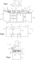
- the equipment (1) according to the invention comprises a piece of furniture (2) formed of a box (4) surmounted by a worktop (5) formed of at least one monolithic substrate (6) in vitroceramic with a surface area of 2.2 m 2 .
- This substrate is for example a plate of the type marketed under the reference KeraBlack+ by the company Eurokera, this plate having a smooth upper face and a lower face provided with studs, and a thickness of 4 mm, and having a brightness L* of 0.23, a blur of 0.75%, a transmission luminous T L of 1.34%, and an opacity indicator of 99.27.
- This substrate is for example obtained by proceeding as in the patent application WO2012156444 but by reducing the speed of passage in the ceramization arch by 50%.
- this substrate may also be, for example, a 1.1 m 2 glass-ceramic plate of the type marketed under the reference KeraVision by the company Eurokera, this plate having a smooth upper face and a smooth lower face, and a thickness of 6 mm, and having a brightness L* of 1.08, a blur of 2.17%, a light transmission T L of 3.69%, and an opacity indicator of 95.69.
- This substrate is for example obtained by proceeding as in the patent application WO2012001300 but by reducing the speed of passage in the ceramization arch by 50%.
- the substrate used has a black color (in both cases mentioned above).
- the glass-ceramic substrate obtained has a flatness of less than 2 mm (the flatness obtained being between 2 and 3 mm for a speed reduced by only 25%, and being more than 15 mm for a speed unchanged compared to that used in the aforementioned application to obtain a plate of standard dimensions less than 0.4 m 2 ), the flatness sought for good optical properties and good thermal coupling and efficiency properties in particular, being less than 3 mm, preferably less than 2 mm.
- the equipment further comprises in the present example three heating elements (7), for example inductors, arranged under the plate (6).
- These inductors are in the present case distributed in the middle of the work surface, but could just as well be located at one end of the plane.
- the equipment also comprises three light sources (8), intended to indicate the cooking locations, and placed under the substrate, these sources being hidden by the substrate when they are at rest. These sources make it possible to indicate the cooking locations, for example using a colored light circle (9) delimiting each location (the colors may be identical or different depending on the locations) and surrounding the inductors, when these sources are activated, or even when the heating elements are activated if the sources are connected to said elements by an appropriate interface. In the present case, the sources are offset laterally relative to the cooking zones (as indicated in figure 2 ), and the light is transmitted to the heating zones via a waveguide (10).
- This optical guide (10) is for example in the form of a 3 mm thick clear borosilicate glass plate and the sources (8) are formed for example of a plurality of LEDs carried by a base housed in a profile, the sources being located on a part of the edge of the guide outside the lighting zones and the heating zones, the article further comprising means for extracting the radiation emitted by the sources, these means being in the form of enamelled or sandblasted zones 11 each located under each of the desired lighting zones.
- the equipment further comprises at least one communication interface (12) (hidden by the substrate) with the heating elements, and where appropriate with the light sources, this interface also communicating wirelessly with an external unit in the form of, for example, a touch pad (13) for activating different zones and functions of the hob or equipment.
- the external unit can advantageously be mobile and rest on the worktop ( figure 1 ) or serve for remote activation ( figure 3 ) of different areas or functions.
- the interface could also comprise or be connected to a fixed control strip located on the surface of the substrate (2) for the activation of different areas and functions, in particular of the substrate.
- the equipment may be associated with or also include an extractor hood (14) overhanging the work surface, this hood also being able to integrate at least one light source (8') for lighting the work surface or signaling the cooking zones (in particular in the latter case when the upper face of the substrate (6) is coated with an opaque enamel).
- an extractor hood (14) overhanging the work surface, this hood also being able to integrate at least one light source (8') for lighting the work surface or signaling the cooking zones (in particular in the latter case when the upper face of the substrate (6) is coated with an opaque enamel).
- the equipment also includes other elements, in particular electric cables (15) for activating the heating elements and for activating the sources, and includes drawers (16) or cupboards (17) arranged in the box supporting the worktop, for storing various items, etc.
- the equipment may also include other elements, for example the worktop may include a frame, the substrate may be coated with a permanent decoration, localized or not, for example in enamel, the
- the cabinet may be solid or have various recesses (such as the recess (18), or may incorporate other elements (e.g. a built-in oven, etc.).
- the worktop (5) may serve various purposes, such as writing (as symbolised by the paper and pen (19)), supporting objects (as symbolised by the dishes (20)) while allowing food to be cooked (as symbolised by the cooking vessels (21)), etc.
- the cabinet may also be replaced by support legs (e.g. only the walls 22 and 23, or four legs at the four corners, the equipment under the worktop in this case being preferably hidden by a localised formwork a few centimetres thick under the substrate) like a table.
- the equipment according to the invention can in particular be used with advantages to produce a new range of multi-use and interactive furniture, notably integrating cooking zones or a cooking function.
Landscapes
- Chemical & Material Sciences (AREA)
- Engineering & Computer Science (AREA)
- General Chemical & Material Sciences (AREA)
- Organic Chemistry (AREA)
- Materials Engineering (AREA)
- Geochemistry & Mineralogy (AREA)
- Life Sciences & Earth Sciences (AREA)
- Chemical Kinetics & Catalysis (AREA)
- General Engineering & Computer Science (AREA)
- Mechanical Engineering (AREA)
- Combustion & Propulsion (AREA)
- Ceramic Engineering (AREA)
- Crystallography & Structural Chemistry (AREA)
- Dispersion Chemistry (AREA)
- Physics & Mathematics (AREA)
- Electromagnetism (AREA)
- Induction Heating Cooking Devices (AREA)
- Surface Treatment Of Glass (AREA)
- Glass Compositions (AREA)
Claims (15)
- Möbel- und/oder Haushaltseinrichtung (1), umfassend:- mindestens eine Arbeitsfläche (5), die aus mindestens einem Substrat (6) aus monolithischem Glasmaterial mit einer Oberfläche von mehr als 0,7 m2 ausgebildet ist, wobei das Glasmaterial einen Undurchsichtigkeitsindikator von mehr als 93 und weniger als 100 vorweist, wobei das Substrat einen Glanz L* von weniger als 10, eine Unschärfe von weniger als 30 % und eine Lichtdurchlässigkeit TL von weniger als 10 % vorweist,- mindestens ein Heizelement (7),- mindestens eine Lichtquelle (8), die dafür bestimmt ist, einen oder mehrere Bereiche oder ein oder mehrere Elemente oder Darstellungen des Substrats zu kennzeichnen, wobei diese Quelle sich unter dem Substrat befindet und durch dieses verdeckt wird, wenn diese Quelle in Ruhe ist,- mindestens eine Kommunikationsschnittstelle (12) zwischen einem Menschen und mindestens einer Maschine, die aus einer Lichtquelle und einem Heizelement ausgewählt ist.
- Einrichtung (1) nach Anspruch 1, dadurch gekennzeichnet, dass die Oberfläche des Substrats (6) aus Glasmaterial mehr als 0,9 m2, besonders mehr als 1 m2, insbesondere mindestens 2 m2, beträgt, wobei die Dicke des Substrats mindestens 2 mm, besonders mindestens 2,5 mm, beträgt, insbesondere in der Größenordnung von 3 bis 30 mm liegt und vorteilhafterweise weniger als 15 mm beträgt, insbesondere in der Größenordnung von 3 bis 15 mm, besonders in der Größenordnung von 3 bis 10 mm, liegt.
- Einrichtung (1) nach einem der Ansprüche 1 oder 2,
dadurch gekennzeichnet, dass das Substrat (6) eine geometrische Form vorweist, die zwischen einem Quadrat und einem Rechteck ausgewählt wird, wobei das Substrat eine Ebenheit von weniger als 0,1 % einer Diagonalen des Quadrats des Substrats oder des Rechtecks des Substrats vorweist, wobei die Ebenheit vorzugsweise weniger als 3 mm, besonders weniger als 2 mm, insbesondere weniger als 1 mm, beträgt oder sogar in der Größenordnung von null liegt. - Einrichtung (1) nach einem der Ansprüche 1 bis 3,
dadurch gekennzeichnet, dass das Substrat (6) aus thermisch vorgespanntem Glas oder aus Glaskeramik und vorzugsweise aus Glaskeramik besteht. - Einrichtung (1) nach einem der Ansprüche 1 bis 4,
dadurch gekennzeichnet, dass das Substrat (6) eine dunkle Erscheinung besitzt und einen Glanz L* von weniger als 5 und eine Unschärfe von weniger als 28 % und eine Lichtdurchlässigkeit TL von weniger als oder gleich 5 % vorweist, wobei diese Lichtdurchlässigkeit ungleich null ist. - Einrichtung (1) nach einem der Ansprüche 1 bis 5,
dadurch gekennzeichnet, dass die Einrichtung (1) als Heizelement(e) (7) ein oder mehrere Induktionsheizmittel umfasst, wobei das oder die Heizelemente in einem oder mehreren Bereichen des Substrats angeordnet oder unter dem Substrat (6) gleichmäßig verteilt sein können, wobei sie beispielsweise mindestens 25 % der Oberfläche des Substrats einnehmen oder mehr als 50 %, besonders mehr als 75 %, oder sogar mehr als 85 %, der Oberfläche des Substrats einnehmen. - Einrichtung (1) nach einem der Ansprüche 1 bis 6,
dadurch gekennzeichnet, dass eine oder mehrere Kochstellen durch die eine oder die mehreren Lichtquelle(n) (8) bei Aktivierung der Quelle gekennzeichnet und/oder hervorgehoben werden, wobei die Quelle eine Lichtanzeige durch Durchlässigkeit mittels der Arbeitsfläche (5) ermöglicht. - Einrichtung (1) nach einem der Ansprüche 1 bis 6,
dadurch gekennzeichnet, dass die sichtbare Seite des Substrats (6) mit einer mattierenden Beschichtung, insbesondere einer Emaille oder Dünnschichten, beschichtet ist, wobei der Bedeckungsgrad der mattierenden Beschichtung in dem beschichteten Bereich mindestens 5 %, vorzugsweise mindestens 20 %, insbesondere mindestens 45 %, oder sogar 100 %, beträgt und die eine oder die mehreren Kochstellen durch mindestens eine weitere Lichtquelle (8) bei der Aktivierung der einen anderen oder den anderen Quellen gekennzeichnet und/oder hervorgehoben werden, wobei die andere Quelle sich auf der Seite der sichtbaren Seite des Substrats (6) oder auf der Seite, an der die Anzeige gesucht wird oder gesehen werden muss, befindet und eine Lichtanzeige durch Projektion auf diese Seite, die einen Bildschirm ausbildet, ermöglicht. - Einrichtung (1) nach Anspruch 8, dadurch gekennzeichnet, dass die sichtbare Seite des Substrats mit einer Emaille, die einen Pigmentgehalt von mehr als 2 %, insbesondere mehr als 5 %, vorzugsweise mehr als 10 %, besonders zwischen 5 und 30 %, vorweist, und/oder einer Emaille, die einen Brechungsindex vorweist, die sich von dem des Substrats unterscheidet, beschichtet ist.
- Einrichtung (1) nach einem der Ansprüche 1 bis 9,
dadurch gekennzeichnet, dass die eine oder die mehreren Lichtquellen (8) durch Kontakt an der Oberfläche der Ebene und/oder an der Schnittstelle (12) und/oder an einer externen Einheit oder durch Handbewegung aktiviert werden können. - Einrichtung (1) nach einem der Ansprüche 1 bis 10,
dadurch gekennzeichnet, dass die Einrichtung ferner mindestens einen Wellenleiter umfasst, wobei die Lichtquelle (8) an den Wellenleiter angeschlossen ist. - Einrichtung (1) nach einem der Ansprüche 1 bis 11,
dadurch gekennzeichnet, dass die Einrichtung mindestens ein optisches Filter, um einen farbigen Lichtbereich der ausgewählten Farbe auszubilden, umfasst, wobei dieses Filter im Allgemeinen zwischen der Quelle (8) und dem Substrat platziert wird und an der Quelle und/oder an dem Substrat (6) und/oder möglicherweise an einem anderen Zwischenelement befestigt werden kann. - Einrichtung (1) nach einem der Ansprüche 1 bis 12,
dadurch gekennzeichnet, dass die Schnittstelle (12) die drahtlose Kommunikation ermöglicht, insbesondere mit einer externen Einheit der Arbeitsfläche, die zum Beispiel die Aktivierung aus der Entfernung der Heizelemente (7) und/oder der Lichtquellen (8) ermöglicht, wobei die externe Einheit zum Beispiel in Form eines Tastenfeldes, eines Tablets oder eines Touchscreens (13) oder eines Mobiltelefons vorliegt, wobei diese Einheit fest oder bewegbar sein kann, wobei die drahtlose Kommunikation zum Beispiel eine begrenzte Reichweite haben kann, zum Beispiel begrenzt auf das Volumen des Teils, in dem sich die Einrichtung befindet. - Einrichtung (1) nach einem der Ansprüche 1 bis 13,
dadurch gekennzeichnet, dass die Einrichtung eine oder mehrere Schnittstellen (12) derselben Art oder unterschiedlicher Art umfasst, die das Koordinieren der Aktivierung der Heizbereiche mit der Aktivierung der Lichtquellen (8) ermöglichen. - Einrichtung (1) nach einem der Ansprüche 1 bis 14,
dadurch gekennzeichnet, dass die Arbeitsfläche (5) insbesondere horizontal auf mindestens einem oder mehreren Stützelementen, wie einem Korpus (4) eines Möbels (2) oder einem oder mehreren Stützfüßen, montiert ist, wobei sie mit den Stützelementen einen Tisch, ein Möbel, massiv oder nicht, oder eine Theke ausbildet.
Applications Claiming Priority (2)
| Application Number | Priority Date | Filing Date | Title |
|---|---|---|---|
| FR1451941A FR3018170B1 (fr) | 2014-03-10 | 2014-03-10 | Plan de travail en vitroceramique |
| PCT/FR2015/050580 WO2015136204A1 (fr) | 2014-03-10 | 2015-03-09 | Plan de travail en vitroceramique de grande taille |
Publications (2)
| Publication Number | Publication Date |
|---|---|
| EP3117149A1 EP3117149A1 (de) | 2017-01-18 |
| EP3117149B1 true EP3117149B1 (de) | 2025-01-29 |
Family
ID=51303063
Family Applications (1)
| Application Number | Title | Priority Date | Filing Date |
|---|---|---|---|
| EP15714591.3A Active EP3117149B1 (de) | 2014-03-10 | 2015-03-09 | Grosse arbeitsplatte aus glaskeramik |
Country Status (9)
| Country | Link |
|---|---|
| US (1) | US10788221B2 (de) |
| EP (1) | EP3117149B1 (de) |
| JP (2) | JP2017512369A (de) |
| KR (1) | KR102301541B1 (de) |
| CN (2) | CN106068425A (de) |
| DE (1) | DE202015006354U1 (de) |
| ES (1) | ES3019415T3 (de) |
| FR (1) | FR3018170B1 (de) |
| WO (1) | WO2015136204A1 (de) |
Families Citing this family (13)
| Publication number | Priority date | Publication date | Assignee | Title |
|---|---|---|---|---|
| EP3031785B1 (de) * | 2014-12-12 | 2018-10-17 | Schott AG | Verfahren zur herstellung eines glaskeramikelements mit strukturierter beschichtung |
| DE102015103389A1 (de) * | 2015-03-09 | 2016-09-15 | Schultheiss Gmbh | Verfahren und Vorrichtung zur Korrektur einer inhomogenen Intensitätsverteilung eines von einer Strahlungsquelle erzeugten Strahlungsfeldes |
| FR3040608B1 (fr) * | 2015-09-08 | 2018-05-25 | Eurokera S.N.C. | Plan de travail en vitroceramique |
| FR3040766B1 (fr) * | 2015-09-08 | 2018-07-27 | Eurokera S.N.C. | Plan de travail en vitroceramique |
| KR102493148B1 (ko) | 2016-03-28 | 2023-01-27 | 엘지전자 주식회사 | 테이블 |
| DE102017123771A1 (de) * | 2017-10-12 | 2019-04-18 | Miele & Cie. Kg | Kochfeldsystem |
| DE102018110855A1 (de) | 2017-12-22 | 2018-06-28 | Schott Ag | Glaskeramik mit reduziertem Lithium-Gehalt |
| DE202018102533U1 (de) * | 2017-12-22 | 2018-06-12 | Schott Ag | Einrichtungs- und Ausstattungsgegenstände für Küchen oder Labore mit Anzeigeeinrichtung |
| DE202018102534U1 (de) | 2017-12-22 | 2018-05-15 | Schott Ag | Transparente, eingefärbte Lithiumaluminiumsilikat-Glaskeramik |
| DE102018110910A1 (de) * | 2017-12-22 | 2018-06-21 | Schott Ag | Einrichtungs- und Ausstattungsgegenstände für Küchen oder Labore mit Leuchtelement |
| DE102018216818B4 (de) | 2018-09-28 | 2020-04-16 | Schott Ag | Arbeitsplatte sowie ein Arbeitstisch umfassend eine Arbeitsplatte |
| WO2020148382A1 (en) * | 2019-01-16 | 2020-07-23 | Carsten Petersen | Tabletop with induction heating module |
| US20200310550A1 (en) * | 2019-03-28 | 2020-10-01 | Ghsp, Inc. | Interactive kitchen display |
Citations (13)
| Publication number | Priority date | Publication date | Assignee | Title |
|---|---|---|---|---|
| EP2217036A1 (de) * | 2009-02-04 | 2010-08-11 | Saint-Gobain Glass France | Küchenarbeitsplatte mit Induktionskochfeld |
| WO2010102859A1 (de) | 2009-03-13 | 2010-09-16 | Schott Ag | Transparente, eingefärbte kochfläche |
| JP4563863B2 (ja) | 2005-05-12 | 2010-10-13 | クリナップ株式会社 | システムキッチン |
| FR2946041A1 (fr) * | 2009-05-29 | 2010-12-03 | Eurokera | Vitroceramiques et articles en vitroceramique, notamment plaques de cuisson, colores |
| FR2955574A1 (fr) * | 2010-01-22 | 2011-07-29 | Eurokera | Vitroceramiques de beta-quartz ; articles en lesdites vitroceramiques ; procedes d'obtention ; verres precursseurs. |
| WO2012001300A1 (fr) * | 2010-06-30 | 2012-01-05 | Eurokera S.N.C. | Dispositif de cuisson |
| WO2012059664A1 (fr) | 2010-11-04 | 2012-05-10 | Eurokera S.N.C. | Article vitroceramique lumineux |
| WO2012076414A1 (de) | 2010-12-08 | 2012-06-14 | Schott Ag | Anzeigevorrichtung, insbesondere für kochflächen |
| WO2012080672A1 (fr) | 2010-12-17 | 2012-06-21 | Eurokera S.N.C. | Dispositif de cuisson par induction |
| US20120263957A1 (en) * | 2010-01-05 | 2012-10-18 | Eurokera S.N.C. | Enamel composition for glass-ceramic |
| WO2012146860A1 (fr) | 2011-04-29 | 2012-11-01 | Eurokera S.N.C. | Dispositif de cuisson par induction |
| WO2012156444A1 (en) | 2011-05-16 | 2012-11-22 | Eurokera | Beta-quartz glass ceramics with controlled transmission and methods of making same. |
| WO2013150014A1 (de) * | 2012-04-05 | 2013-10-10 | BSH Bosch und Siemens Hausgeräte GmbH | Kochfeld und verfahren zur steuerung eines kochfeldes |
Family Cites Families (24)
| Publication number | Priority date | Publication date | Assignee | Title |
|---|---|---|---|---|
| FR1060677A (fr) | 1952-07-30 | 1954-04-05 | Neyret Beylier Atel | Perfectionnement aux appareils de raffinage pour pâte à papier |
| FR1363157A (fr) | 1963-01-31 | 1964-06-12 | Dispositif de distribution de pièces de monnaie | |
| FR2609533B1 (fr) * | 1987-01-13 | 1990-05-25 | Cableco Sa | Plan de cuisson electrique a chauffage a induction |
| FR2657079B1 (fr) | 1990-01-12 | 1993-04-09 | Corning France | Verres precurseurs de vitroceramiques, procede de conversion de ces verres en vitroceramiques a dilation tres faible ou nulle et vitroceramiques obtenues. |
| FR2766816B1 (fr) * | 1997-08-01 | 1999-08-27 | Eurokera | Plaque vitroceramique et son procede de fabrication |
| AU1174500A (en) * | 1998-11-24 | 2000-06-13 | Jonathan Bennett | Glass objects comprising a plurality of stacked glass elements |
| CN2638524Y (zh) * | 2003-06-09 | 2004-09-08 | 梁佩玲 | 家用多功能电子餐桌 |
| FR2864071A1 (fr) * | 2003-12-17 | 2005-06-24 | Snc Eurokera | Vitroceramiques, verres precurseurs, articles en lesdites vitroceramiques, elaboration desdits vitroceramiques et articles |
| FR2885995B1 (fr) * | 2005-05-20 | 2007-07-06 | Eurokera | Plaque vitroceramique et son procede de fabrication |
| JP4665701B2 (ja) * | 2005-10-13 | 2011-04-06 | パナソニック株式会社 | 加熱調理器 |
| FR2894328B1 (fr) * | 2005-12-05 | 2017-10-06 | Eurokera | Plaque vitroceramique transparente ou translucide et son procede de fabrication |
| DE102006027739B4 (de) * | 2006-06-16 | 2008-05-29 | Schott Ag | Kochfeld mit einer Glaskeramikplatte als Kochfläche |
| EP3671044B1 (de) * | 2006-09-27 | 2022-01-05 | Electrolux Home Products Corporation N.V. | Kochgerät |
| FR2913262B1 (fr) * | 2007-03-02 | 2013-09-06 | Eurokera | Plaque vitroceramique et son procede de fabrication. |
| JP2009211861A (ja) * | 2008-03-03 | 2009-09-17 | Panasonic Corp | 誘導加熱調理器およびそのプログラム |
| JP5338304B2 (ja) * | 2008-12-25 | 2013-11-13 | 鳴海製陶株式会社 | 加熱調理器用ガラストッププレート |
| CN201422584Y (zh) * | 2009-05-15 | 2010-03-17 | 杨泽斌 | 一种电磁加热合成家具 |
| EP2392859B1 (de) * | 2010-05-05 | 2017-03-29 | Electrolux Home Products Corporation N.V. | Herdplattenschnittstelle, Herdplattenkochfeld, Kochvorrichtung und Verfahren zum Betreiben einer Herdplattenschnittstelle |
| CN202209711U (zh) * | 2011-03-11 | 2012-05-02 | 杨俊新 | 电磁-电阻组合厨具 |
| CN202082982U (zh) * | 2011-06-03 | 2011-12-21 | 郝立华 | 带电磁炉的面板结构 |
| FR2976683B1 (fr) * | 2011-06-15 | 2013-11-08 | Eurokera | Article vitroceramique a affichage lumineux colore. |
| DE102011115379B4 (de) * | 2011-10-10 | 2018-09-27 | Schott Ag | Beschichtetes Glas- oder Glaskeramik-Substrat mit haptischen Eigenschaften und Glaskeramik-Kochfeld |
| DE202011109214U1 (de) * | 2011-12-16 | 2012-01-25 | Vetro Küche + Glas KG | Küchenarbeitsplatte |
| FR2994568B1 (fr) | 2012-08-14 | 2021-06-04 | Eurokera | Article vitroceramique a affichage lumineux colore |
-
2014
- 2014-03-10 FR FR1451941A patent/FR3018170B1/fr active Active
-
2015
- 2015-03-09 WO PCT/FR2015/050580 patent/WO2015136204A1/fr not_active Ceased
- 2015-03-09 US US15/124,396 patent/US10788221B2/en active Active
- 2015-03-09 EP EP15714591.3A patent/EP3117149B1/de active Active
- 2015-03-09 DE DE202015006354.3U patent/DE202015006354U1/de not_active Expired - Lifetime
- 2015-03-09 CN CN201580013006.5A patent/CN106068425A/zh active Pending
- 2015-03-09 ES ES15714591T patent/ES3019415T3/es active Active
- 2015-03-09 KR KR1020167024690A patent/KR102301541B1/ko active Active
- 2015-03-09 CN CN202210266550.2A patent/CN114719306A/zh active Pending
- 2015-03-09 JP JP2016556789A patent/JP2017512369A/ja not_active Withdrawn
-
2020
- 2020-05-01 JP JP2020081324A patent/JP2020128863A/ja active Pending
Patent Citations (13)
| Publication number | Priority date | Publication date | Assignee | Title |
|---|---|---|---|---|
| JP4563863B2 (ja) | 2005-05-12 | 2010-10-13 | クリナップ株式会社 | システムキッチン |
| EP2217036A1 (de) * | 2009-02-04 | 2010-08-11 | Saint-Gobain Glass France | Küchenarbeitsplatte mit Induktionskochfeld |
| WO2010102859A1 (de) | 2009-03-13 | 2010-09-16 | Schott Ag | Transparente, eingefärbte kochfläche |
| FR2946041A1 (fr) * | 2009-05-29 | 2010-12-03 | Eurokera | Vitroceramiques et articles en vitroceramique, notamment plaques de cuisson, colores |
| US20120263957A1 (en) * | 2010-01-05 | 2012-10-18 | Eurokera S.N.C. | Enamel composition for glass-ceramic |
| FR2955574A1 (fr) * | 2010-01-22 | 2011-07-29 | Eurokera | Vitroceramiques de beta-quartz ; articles en lesdites vitroceramiques ; procedes d'obtention ; verres precursseurs. |
| WO2012001300A1 (fr) * | 2010-06-30 | 2012-01-05 | Eurokera S.N.C. | Dispositif de cuisson |
| WO2012059664A1 (fr) | 2010-11-04 | 2012-05-10 | Eurokera S.N.C. | Article vitroceramique lumineux |
| WO2012076414A1 (de) | 2010-12-08 | 2012-06-14 | Schott Ag | Anzeigevorrichtung, insbesondere für kochflächen |
| WO2012080672A1 (fr) | 2010-12-17 | 2012-06-21 | Eurokera S.N.C. | Dispositif de cuisson par induction |
| WO2012146860A1 (fr) | 2011-04-29 | 2012-11-01 | Eurokera S.N.C. | Dispositif de cuisson par induction |
| WO2012156444A1 (en) | 2011-05-16 | 2012-11-22 | Eurokera | Beta-quartz glass ceramics with controlled transmission and methods of making same. |
| WO2013150014A1 (de) * | 2012-04-05 | 2013-10-10 | BSH Bosch und Siemens Hausgeräte GmbH | Kochfeld und verfahren zur steuerung eines kochfeldes |
Non-Patent Citations (2)
| Title |
|---|
| ANONYMOUS: "Opazität", WIKIPEDIA, 21 August 2025 (2025-08-21), XP093332266, Retrieved from the Internet <URL:https://de.wikipedia.org/w/index.php?title=Opazität&oldid=259070506> |
| D3 - SCHOTT AG: "SCHOTT INFO 101/2002, veröffentlicht 2002 auf der Internetpräsenz der Schott-AG", 1 January 2002 (2002-01-01) |
Also Published As
| Publication number | Publication date |
|---|---|
| JP2017512369A (ja) | 2017-05-18 |
| JP2020128863A (ja) | 2020-08-27 |
| CN106068425A (zh) | 2016-11-02 |
| US10788221B2 (en) | 2020-09-29 |
| ES3019415T3 (en) | 2025-05-20 |
| KR20160131015A (ko) | 2016-11-15 |
| WO2015136204A1 (fr) | 2015-09-17 |
| FR3018170A1 (fr) | 2015-09-11 |
| KR102301541B1 (ko) | 2021-09-15 |
| US20170016627A1 (en) | 2017-01-19 |
| EP3117149A1 (de) | 2017-01-18 |
| DE202015006354U1 (de) | 2015-11-03 |
| CN114719306A (zh) | 2022-07-08 |
| FR3018170B1 (fr) | 2017-01-27 |
Similar Documents
| Publication | Publication Date | Title |
|---|---|---|
| EP3117150B1 (de) | Möbel- oder haushaltsausstattung mit einer grossen arbeitsplatte aus glasmaterial | |
| EP3117151B1 (de) | Grosse arbeitsplatte aus glasmaterial | |
| EP3346878B1 (de) | Glas-keramik-arbeitsplatte | |
| WO2015136204A1 (fr) | Plan de travail en vitroceramique de grande taille | |
| EP2721349B1 (de) | Glaskeramischer artikel mit leuchtender farbanzeige | |
| EP3346876B1 (de) | Interaktive möbel und/oder interaktive haushaltgeräte | |
| EP2935136B1 (de) | Glaskeramikartikel mit leuchtanzeige | |
| EP3346877A1 (de) | Glaskeramikarbeitsplatte | |
| EP3755666A1 (de) | Glaskeramikartikel | |
| EP3346875A1 (de) | Glaskeramikarbeitsplatte | |
| EP3346873B1 (de) | Glaskeramikarbeitsplatte | |
| EP3347318A1 (de) | Glaskeramikarbeitsplatte | |
| EP3347316A1 (de) | Glaskeramikarbeitsplatte | |
| EP3347317A1 (de) | Glaskeramikarbeitsplatte | |
| EP3346879A1 (de) | Glaskeramikarbeitsplatte |
Legal Events
| Date | Code | Title | Description |
|---|---|---|---|
| STAA | Information on the status of an ep patent application or granted ep patent |
Free format text: STATUS: THE INTERNATIONAL PUBLICATION HAS BEEN MADE |
|
| PUAI | Public reference made under article 153(3) epc to a published international application that has entered the european phase |
Free format text: ORIGINAL CODE: 0009012 |
|
| STAA | Information on the status of an ep patent application or granted ep patent |
Free format text: STATUS: REQUEST FOR EXAMINATION WAS MADE |
|
| 17P | Request for examination filed |
Effective date: 20161010 |
|
| AK | Designated contracting states |
Kind code of ref document: A1 Designated state(s): AL AT BE BG CH CY CZ DE DK EE ES FI FR GB GR HR HU IE IS IT LI LT LU LV MC MK MT NL NO PL PT RO RS SE SI SK SM TR |
|
| AX | Request for extension of the european patent |
Extension state: BA ME |
|
| RIN1 | Information on inventor provided before grant (corrected) |
Inventor name: FERNANDEZ, JAVIER Inventor name: RAVEL, MICHAEL Inventor name: VILATO, PABLO Inventor name: CHARPENTIER, BERTRAND Inventor name: LISMONDE, MICHEL Inventor name: ROUX, NICOLAS |
|
| DAV | Request for validation of the european patent (deleted) | ||
| DAX | Request for extension of the european patent (deleted) | ||
| TPAC | Observations filed by third parties |
Free format text: ORIGINAL CODE: EPIDOSNTIPA |
|
| STAA | Information on the status of an ep patent application or granted ep patent |
Free format text: STATUS: EXAMINATION IS IN PROGRESS |
|
| 17Q | First examination report despatched |
Effective date: 20190425 |
|
| REG | Reference to a national code |
Ref country code: DE Ref legal event code: R079 Free format text: PREVIOUS MAIN CLASS: F24C0007080000 Ipc: C03C0003083000 Ref country code: DE Ref legal event code: R079 Ref document number: 602015090935 Country of ref document: DE Free format text: PREVIOUS MAIN CLASS: F24C0007080000 Ipc: C03C0003083000 |
|
| RIC1 | Information provided on ipc code assigned before grant |
Ipc: F24C 15/10 20060101ALI20240823BHEP Ipc: C03C 10/00 20060101ALI20240823BHEP Ipc: F24C 7/08 20060101ALI20240823BHEP Ipc: C03C 3/097 20060101ALI20240823BHEP Ipc: C03C 3/087 20060101ALI20240823BHEP Ipc: C03C 3/085 20060101ALI20240823BHEP Ipc: C03C 3/083 20060101AFI20240823BHEP |
|
| GRAP | Despatch of communication of intention to grant a patent |
Free format text: ORIGINAL CODE: EPIDOSNIGR1 |
|
| STAA | Information on the status of an ep patent application or granted ep patent |
Free format text: STATUS: GRANT OF PATENT IS INTENDED |
|
| INTG | Intention to grant announced |
Effective date: 20241008 |
|
| GRAS | Grant fee paid |
Free format text: ORIGINAL CODE: EPIDOSNIGR3 |
|
| GRAA | (expected) grant |
Free format text: ORIGINAL CODE: 0009210 |
|
| STAA | Information on the status of an ep patent application or granted ep patent |
Free format text: STATUS: THE PATENT HAS BEEN GRANTED |
|
| AK | Designated contracting states |
Kind code of ref document: B1 Designated state(s): AL AT BE BG CH CY CZ DE DK EE ES FI FR GB GR HR HU IE IS IT LI LT LU LV MC MK MT NL NO PL PT RO RS SE SI SK SM TR |
|
| REG | Reference to a national code |
Ref country code: GB Ref legal event code: FG4D Free format text: NOT ENGLISH |
|
| REG | Reference to a national code |
Ref country code: CH Ref legal event code: EP |
|
| REG | Reference to a national code |
Ref country code: DE Ref legal event code: R096 Ref document number: 602015090935 Country of ref document: DE |
|
| REG | Reference to a national code |
Ref country code: IE Ref legal event code: FG4D Free format text: LANGUAGE OF EP DOCUMENT: FRENCH |
|
| P01 | Opt-out of the competence of the unified patent court (upc) registered |
Free format text: CASE NUMBER: APP_10457/2025 Effective date: 20250303 |
|
| REG | Reference to a national code |
Ref country code: ES Ref legal event code: FG2A Ref document number: 3019415 Country of ref document: ES Kind code of ref document: T3 Effective date: 20250520 |
|
| REG | Reference to a national code |
Ref country code: NL Ref legal event code: MP Effective date: 20250129 |
|
| PG25 | Lapsed in a contracting state [announced via postgrant information from national office to epo] |
Ref country code: NL Free format text: LAPSE BECAUSE OF FAILURE TO SUBMIT A TRANSLATION OF THE DESCRIPTION OR TO PAY THE FEE WITHIN THE PRESCRIBED TIME-LIMIT Effective date: 20250129 |
|
| PG25 | Lapsed in a contracting state [announced via postgrant information from national office to epo] |
Ref country code: RS Free format text: LAPSE BECAUSE OF FAILURE TO SUBMIT A TRANSLATION OF THE DESCRIPTION OR TO PAY THE FEE WITHIN THE PRESCRIBED TIME-LIMIT Effective date: 20250429 |
|
| PG25 | Lapsed in a contracting state [announced via postgrant information from national office to epo] |
Ref country code: FI Free format text: LAPSE BECAUSE OF FAILURE TO SUBMIT A TRANSLATION OF THE DESCRIPTION OR TO PAY THE FEE WITHIN THE PRESCRIBED TIME-LIMIT Effective date: 20250129 |
|
| PG25 | Lapsed in a contracting state [announced via postgrant information from national office to epo] |
Ref country code: PL Free format text: LAPSE BECAUSE OF FAILURE TO SUBMIT A TRANSLATION OF THE DESCRIPTION OR TO PAY THE FEE WITHIN THE PRESCRIBED TIME-LIMIT Effective date: 20250129 |
|
| PGFP | Annual fee paid to national office [announced via postgrant information from national office to epo] |
Ref country code: ES Payment date: 20250414 Year of fee payment: 11 |
|
| REG | Reference to a national code |
Ref country code: LT Ref legal event code: MG9D |
|
| PG25 | Lapsed in a contracting state [announced via postgrant information from national office to epo] |
Ref country code: IS Free format text: LAPSE BECAUSE OF FAILURE TO SUBMIT A TRANSLATION OF THE DESCRIPTION OR TO PAY THE FEE WITHIN THE PRESCRIBED TIME-LIMIT Effective date: 20250529 Ref country code: NO Free format text: LAPSE BECAUSE OF FAILURE TO SUBMIT A TRANSLATION OF THE DESCRIPTION OR TO PAY THE FEE WITHIN THE PRESCRIBED TIME-LIMIT Effective date: 20250429 |
|
| REG | Reference to a national code |
Ref country code: AT Ref legal event code: MK05 Ref document number: 1763343 Country of ref document: AT Kind code of ref document: T Effective date: 20250129 |
|
| PG25 | Lapsed in a contracting state [announced via postgrant information from national office to epo] |
Ref country code: HR Free format text: LAPSE BECAUSE OF FAILURE TO SUBMIT A TRANSLATION OF THE DESCRIPTION OR TO PAY THE FEE WITHIN THE PRESCRIBED TIME-LIMIT Effective date: 20250129 |
|
| PG25 | Lapsed in a contracting state [announced via postgrant information from national office to epo] |
Ref country code: PT Free format text: LAPSE BECAUSE OF FAILURE TO SUBMIT A TRANSLATION OF THE DESCRIPTION OR TO PAY THE FEE WITHIN THE PRESCRIBED TIME-LIMIT Effective date: 20250529 Ref country code: LV Free format text: LAPSE BECAUSE OF FAILURE TO SUBMIT A TRANSLATION OF THE DESCRIPTION OR TO PAY THE FEE WITHIN THE PRESCRIBED TIME-LIMIT Effective date: 20250129 |
|
| PG25 | Lapsed in a contracting state [announced via postgrant information from national office to epo] |
Ref country code: GR Free format text: LAPSE BECAUSE OF FAILURE TO SUBMIT A TRANSLATION OF THE DESCRIPTION OR TO PAY THE FEE WITHIN THE PRESCRIBED TIME-LIMIT Effective date: 20250430 Ref country code: BG Free format text: LAPSE BECAUSE OF FAILURE TO SUBMIT A TRANSLATION OF THE DESCRIPTION OR TO PAY THE FEE WITHIN THE PRESCRIBED TIME-LIMIT Effective date: 20250129 |
|
| PG25 | Lapsed in a contracting state [announced via postgrant information from national office to epo] |
Ref country code: AT Free format text: LAPSE BECAUSE OF FAILURE TO SUBMIT A TRANSLATION OF THE DESCRIPTION OR TO PAY THE FEE WITHIN THE PRESCRIBED TIME-LIMIT Effective date: 20250129 |
|
| PG25 | Lapsed in a contracting state [announced via postgrant information from national office to epo] |
Ref country code: SE Free format text: LAPSE BECAUSE OF FAILURE TO SUBMIT A TRANSLATION OF THE DESCRIPTION OR TO PAY THE FEE WITHIN THE PRESCRIBED TIME-LIMIT Effective date: 20250129 |
|
| PG25 | Lapsed in a contracting state [announced via postgrant information from national office to epo] |
Ref country code: SM Free format text: LAPSE BECAUSE OF FAILURE TO SUBMIT A TRANSLATION OF THE DESCRIPTION OR TO PAY THE FEE WITHIN THE PRESCRIBED TIME-LIMIT Effective date: 20250129 |
|
| PG25 | Lapsed in a contracting state [announced via postgrant information from national office to epo] |
Ref country code: DK Free format text: LAPSE BECAUSE OF FAILURE TO SUBMIT A TRANSLATION OF THE DESCRIPTION OR TO PAY THE FEE WITHIN THE PRESCRIBED TIME-LIMIT Effective date: 20250129 |
|
| PG25 | Lapsed in a contracting state [announced via postgrant information from national office to epo] |
Ref country code: MC Free format text: LAPSE BECAUSE OF FAILURE TO SUBMIT A TRANSLATION OF THE DESCRIPTION OR TO PAY THE FEE WITHIN THE PRESCRIBED TIME-LIMIT Effective date: 20250129 |
|
| PG25 | Lapsed in a contracting state [announced via postgrant information from national office to epo] |
Ref country code: EE Free format text: LAPSE BECAUSE OF FAILURE TO SUBMIT A TRANSLATION OF THE DESCRIPTION OR TO PAY THE FEE WITHIN THE PRESCRIBED TIME-LIMIT Effective date: 20250129 Ref country code: CZ Free format text: LAPSE BECAUSE OF FAILURE TO SUBMIT A TRANSLATION OF THE DESCRIPTION OR TO PAY THE FEE WITHIN THE PRESCRIBED TIME-LIMIT Effective date: 20250129 |
|
| REG | Reference to a national code |
Ref country code: CH Ref legal event code: H13 Free format text: ST27 STATUS EVENT CODE: U-0-0-H10-H13 (AS PROVIDED BY THE NATIONAL OFFICE) Effective date: 20251023 |
|
| PG25 | Lapsed in a contracting state [announced via postgrant information from national office to epo] |
Ref country code: RO Free format text: LAPSE BECAUSE OF FAILURE TO SUBMIT A TRANSLATION OF THE DESCRIPTION OR TO PAY THE FEE WITHIN THE PRESCRIBED TIME-LIMIT Effective date: 20250129 |
|
| PG25 | Lapsed in a contracting state [announced via postgrant information from national office to epo] |
Ref country code: SK Free format text: LAPSE BECAUSE OF FAILURE TO SUBMIT A TRANSLATION OF THE DESCRIPTION OR TO PAY THE FEE WITHIN THE PRESCRIBED TIME-LIMIT Effective date: 20250129 |
|
| REG | Reference to a national code |
Ref country code: DE Ref legal event code: R026 Ref document number: 602015090935 Country of ref document: DE |
|
| PLBI | Opposition filed |
Free format text: ORIGINAL CODE: 0009260 |
|
| PLAX | Notice of opposition and request to file observation + time limit sent |
Free format text: ORIGINAL CODE: EPIDOSNOBS2 |
|
| PG25 | Lapsed in a contracting state [announced via postgrant information from national office to epo] |
Ref country code: LU Free format text: LAPSE BECAUSE OF NON-PAYMENT OF DUE FEES Effective date: 20250309 |
|
| 26 | Opposition filed |
Opponent name: SCHOTT AG Effective date: 20251028 |
|
| REG | Reference to a national code |
Ref country code: BE Ref legal event code: MM Effective date: 20250331 |
|
| GBPC | Gb: european patent ceased through non-payment of renewal fee |
Effective date: 20250429 |
|
| PG25 | Lapsed in a contracting state [announced via postgrant information from national office to epo] |
Ref country code: GB Free format text: LAPSE BECAUSE OF NON-PAYMENT OF DUE FEES Effective date: 20250429 |
|
| PG25 | Lapsed in a contracting state [announced via postgrant information from national office to epo] |
Ref country code: BE Free format text: LAPSE BECAUSE OF NON-PAYMENT OF DUE FEES Effective date: 20250331 |
|
| PG25 | Lapsed in a contracting state [announced via postgrant information from national office to epo] |
Ref country code: CH Free format text: LAPSE BECAUSE OF NON-PAYMENT OF DUE FEES Effective date: 20250331 |
|
| PG25 | Lapsed in a contracting state [announced via postgrant information from national office to epo] |
Ref country code: IE Free format text: LAPSE BECAUSE OF NON-PAYMENT OF DUE FEES Effective date: 20250309 |
|
| PLBB | Reply of patent proprietor to notice(s) of opposition received |
Free format text: ORIGINAL CODE: EPIDOSNOBS3 |
|
| PGFP | Annual fee paid to national office [announced via postgrant information from national office to epo] |
Ref country code: DE Payment date: 20260121 Year of fee payment: 12 |
|
| PGFP | Annual fee paid to national office [announced via postgrant information from national office to epo] |
Ref country code: IT Payment date: 20260220 Year of fee payment: 12 |
|
| PGFP | Annual fee paid to national office [announced via postgrant information from national office to epo] |
Ref country code: FR Payment date: 20260121 Year of fee payment: 12 |
|
| PGFP | Annual fee paid to national office [announced via postgrant information from national office to epo] |
Ref country code: TR Payment date: 20260306 Year of fee payment: 12 |