EP3117484B1 - Antennensystem für polarisationsdiversität - Google Patents
Antennensystem für polarisationsdiversität Download PDFInfo
- Publication number
- EP3117484B1 EP3117484B1 EP14885561.2A EP14885561A EP3117484B1 EP 3117484 B1 EP3117484 B1 EP 3117484B1 EP 14885561 A EP14885561 A EP 14885561A EP 3117484 B1 EP3117484 B1 EP 3117484B1
- Authority
- EP
- European Patent Office
- Prior art keywords
- antenna
- common
- signal
- elongated conductive
- legs
- Prior art date
- Legal status (The legal status is an assumption and is not a legal conclusion. Google has not performed a legal analysis and makes no representation as to the accuracy of the status listed.)
- Active
Links
Images




Classifications
-
- G—PHYSICS
- G01—MEASURING; TESTING
- G01S—RADIO DIRECTION-FINDING; RADIO NAVIGATION; DETERMINING DISTANCE OR VELOCITY BY USE OF RADIO WAVES; LOCATING OR PRESENCE-DETECTING BY USE OF THE REFLECTION OR RERADIATION OF RADIO WAVES; ANALOGOUS ARRANGEMENTS USING OTHER WAVES
- G01S7/00—Details of systems according to groups G01S13/00, G01S15/00, G01S17/00
- G01S7/02—Details of systems according to groups G01S13/00, G01S15/00, G01S17/00 of systems according to group G01S13/00
- G01S7/024—Details of systems according to groups G01S13/00, G01S15/00, G01S17/00 of systems according to group G01S13/00 using polarisation effects
-
- G—PHYSICS
- G01—MEASURING; TESTING
- G01S—RADIO DIRECTION-FINDING; RADIO NAVIGATION; DETERMINING DISTANCE OR VELOCITY BY USE OF RADIO WAVES; LOCATING OR PRESENCE-DETECTING BY USE OF THE REFLECTION OR RERADIATION OF RADIO WAVES; ANALOGOUS ARRANGEMENTS USING OTHER WAVES
- G01S7/00—Details of systems according to groups G01S13/00, G01S15/00, G01S17/00
- G01S7/02—Details of systems according to groups G01S13/00, G01S15/00, G01S17/00 of systems according to group G01S13/00
- G01S7/024—Details of systems according to groups G01S13/00, G01S15/00, G01S17/00 of systems according to group G01S13/00 using polarisation effects
- G01S7/025—Details of systems according to groups G01S13/00, G01S15/00, G01S17/00 of systems according to group G01S13/00 using polarisation effects involving the transmission of linearly polarised waves
-
- G—PHYSICS
- G01—MEASURING; TESTING
- G01S—RADIO DIRECTION-FINDING; RADIO NAVIGATION; DETERMINING DISTANCE OR VELOCITY BY USE OF RADIO WAVES; LOCATING OR PRESENCE-DETECTING BY USE OF THE REFLECTION OR RERADIATION OF RADIO WAVES; ANALOGOUS ARRANGEMENTS USING OTHER WAVES
- G01S7/00—Details of systems according to groups G01S13/00, G01S15/00, G01S17/00
- G01S7/02—Details of systems according to groups G01S13/00, G01S15/00, G01S17/00 of systems according to group G01S13/00
- G01S7/024—Details of systems according to groups G01S13/00, G01S15/00, G01S17/00 of systems according to group G01S13/00 using polarisation effects
- G01S7/026—Details of systems according to groups G01S13/00, G01S15/00, G01S17/00 of systems according to group G01S13/00 using polarisation effects involving the transmission of elliptically or circularly polarised waves
-
- G—PHYSICS
- G01—MEASURING; TESTING
- G01S—RADIO DIRECTION-FINDING; RADIO NAVIGATION; DETERMINING DISTANCE OR VELOCITY BY USE OF RADIO WAVES; LOCATING OR PRESENCE-DETECTING BY USE OF THE REFLECTION OR RERADIATION OF RADIO WAVES; ANALOGOUS ARRANGEMENTS USING OTHER WAVES
- G01S7/00—Details of systems according to groups G01S13/00, G01S15/00, G01S17/00
- G01S7/02—Details of systems according to groups G01S13/00, G01S15/00, G01S17/00 of systems according to group G01S13/00
- G01S7/03—Details of HF subsystems specially adapted therefor, e.g. common to transmitter and receiver
-
- H—ELECTRICITY
- H01—ELECTRIC ELEMENTS
- H01Q—ANTENNAS, i.e. RADIO AERIALS
- H01Q1/00—Details of, or arrangements associated with, antennas
- H01Q1/27—Adaptation for use in or on movable bodies
- H01Q1/28—Adaptation for use in or on aircraft, missiles, satellites, or balloons
-
- H—ELECTRICITY
- H01—ELECTRIC ELEMENTS
- H01Q—ANTENNAS, i.e. RADIO AERIALS
- H01Q1/00—Details of, or arrangements associated with, antennas
- H01Q1/48—Earthing means; Earth screens; Counterpoises
-
- H—ELECTRICITY
- H01—ELECTRIC ELEMENTS
- H01Q—ANTENNAS, i.e. RADIO AERIALS
- H01Q11/00—Electrically-long antennas having dimensions more than twice the shortest operating wavelength and consisting of conductive active radiating elements
- H01Q11/12—Resonant antennas
- H01Q11/14—Resonant antennas with parts bent, folded, shaped or screened or with phasing impedances, to obtain desired phase relation of radiation from selected sections of the antenna or to obtain desired polarisation effect
-
- H—ELECTRICITY
- H01—ELECTRIC ELEMENTS
- H01Q—ANTENNAS, i.e. RADIO AERIALS
- H01Q7/00—Loop antennas with a substantially uniform current distribution around the loop and having a directional radiation pattern in a plane perpendicular to the plane of the loop
-
- H—ELECTRICITY
- H04—ELECTRIC COMMUNICATION TECHNIQUE
- H04B—TRANSMISSION
- H04B7/00—Radio transmission systems, i.e. using radiation field
- H04B7/02—Diversity systems; Multi-antenna system, i.e. transmission or reception using multiple antennas
- H04B7/10—Polarisation diversity; Directional diversity
-
- G—PHYSICS
- G01—MEASURING; TESTING
- G01S—RADIO DIRECTION-FINDING; RADIO NAVIGATION; DETERMINING DISTANCE OR VELOCITY BY USE OF RADIO WAVES; LOCATING OR PRESENCE-DETECTING BY USE OF THE REFLECTION OR RERADIATION OF RADIO WAVES; ANALOGOUS ARRANGEMENTS USING OTHER WAVES
- G01S13/00—Systems using the reflection or reradiation of radio waves, e.g. radar systems; Analogous systems using reflection or reradiation of waves whose nature or wavelength is irrelevant or unspecified
- G01S13/88—Radar or analogous systems specially adapted for specific applications
- G01S13/885—Radar or analogous systems specially adapted for specific applications for ground probing
-
- H—ELECTRICITY
- H01—ELECTRIC ELEMENTS
- H01Q—ANTENNAS, i.e. RADIO AERIALS
- H01Q25/00—Antennas or antenna systems providing at least two radiating patterns
Definitions
- the present disclosure relates to an antenna system for transmission and reception of polarized signals, and in particular to transmission and reception of polarized radar signals.
- Low frequency radar systems i.e., involving wavelengths on the order of meters, and airborne low frequency radar systems in particular, can be used for finding targets buried under ground or hidden below camouflage or trees.
- Low frequency radar systems can also be applied in establishing environmental parameters such as biomass.
- antennas must be physically quite large - the smallest high efficiency antenna is half a wavelength dipole, meaning that such dipoles will be of meter size.
- a dipole is not directive in contrast to conventional radar antennas, which extends for many wavelengths not only in one dimension, as a dipole, but in two dimensions. Just scaling such antennas is clearly not feasible for low frequency radar.
- dipoles are often required to be wideband in the sense that the radar often needs to function and keep a reasonably constant antenna diagram or antenna pattern across a bandwidth of at least octave order.
- the polarization state of transmitted and received radar signals must often be controllable or selectable.
- the polarization state also needs to be alternated with kHz order switching frequency, or used in parallel for horizontal and vertical polarization, so that radar response for both polarizations can be collected.
- US2007/0024514 discloses an energy density diversity antenna (EDA) having a least a pair of antenna elements, whose feeding points are connected to outputs of a hybrid coupler configured such that a sum and a difference signal may exist at the feed point of the antenna elements.
- EDA energy density diversity antenna
- Reactive elements are arranged with a U shape.
- An object of the present disclosure is to provide antenna systems, vehicles, and methods, which seek to mitigate, alleviate, or eliminate one or more of the above-identified deficiencies in the art and disadvantages singly or in any combination.
- the antenna system of independent claim 1 comprising an antenna structure consisting of a single antenna element having first and second antenna ports arranged to pass a respective first and second antenna signal.
- the first and second antenna signals arranged to be derived from a first common antenna signal and also arranged to be essentially equal in envelope.
- the antenna structure is arranged to have an antenna pattern which is selectable between a first antenna pattern having a first polarization and a second antenna pattern having a second polarization substantially orthogonal to the first polarization.
- the first antenna pattern is selected by setting the first and second antenna signal to have the same polarity on first and second antenna ports.
- the second antenna pattern is selected by setting the first and second antenna signal to have substantially opposite polarities on first and second antenna ports.
- the antenna structure comprises an elongated conductive bridge having a length between first and second ends smaller than half of the wavelength corresponding to the highest frequency of the first common antenna signal.
- the antenna structure further comprises two elongated conductive legs arranged in parallel and having respective lengths between first and second ends smaller than half of the wavelength corresponding to the highest frequency of the first common antenna signal. Said legs are attached at first leg ends to either end of the elongated conductive bridge in right angles with respect to the conductive bridge, thus substantially forming a U-shape.
- the sum of lengths of the elongated conductive bridge and the two elongated conductive legs is substantially equal to half of the wavelength corresponding to the center frequency of the first common antenna signal.
- the first antenna port is connected to the second end of one leg, the second antenna port is connected to the second end of the other leg.
- the antenna structure is arranged to have a ground plane orthogonal to both legs and located approximately at the second ends of the legs.
- the antenna structure has a total length, including elongated conductive bridge and both legs, less than the wavelength corresponding to the highest frequency of the first common antenna signal.
- the elongated conductive bridge is extended by first and second conductive extension units connected at either end of the elongated conductive bridge, thus substantially forming a ⁇ -shape, the total length of the elongated conductive bridge with extension units being smaller than the wavelength corresponding to the highest frequency of the fist common antenna signal.
- an antenna system particularly suitable for use with low frequency radar systems in that the antenna system is compact in terms of size due to the single antenna element, which is an advantage.
- the provided antenna system brings an additional advantage in that the polarization state of transmitted and received signals can be controlled or selected in a straightforward way by setting the polarities of the first and second antenna signal.
- any of the U-shape or ⁇ -shaped antenna structures disclosed herein there is provided a wideband antenna of comparably small size which facilitates attaining compliancy with, e.g., aeromechanical requirements and where the polarization state of the transmitted and received signals can be controlled and also alternated or even used in parallel for horizontal and vertical polarization so that, e.g., radar response for both polarizations ca n be collected.
- a wideband antenna of comparably small size which facilitates attaining compliancy with, e.g., aeromechanical requirements and where the polarization state of the transmitted and received signals can be controlled and also alternated or even used in parallel for horizontal and vertical polarization so that, e.g., radar response for both polarizations ca n be collected.
- the antenna system further comprises a first antenna interface unit comprising a 180 degree hybrid coupler, a switching unit, and a first common port for passing the first common antenna signal.
- the 180 degree hybrid coupler has first and second coupler ports connected to the first and to the second antenna port, respectively, as well as a summation and a difference port connected to the switching unit.
- the switching unit is arranged to connect the first common port of the antenna interface unit to either of the summation port or the difference port of the 180 degree hybrid coupler, thus selecting between the first and the second antenna pattern of the antenna system.
- the antenna interface unit connecting a radar transceiver to the antenna system is facilitated, which is an advantage. Further, switching between polarization states, i.e., selecting the polarization of transmitted and received signals, is simplified due to the feature of the switching unit, which is also an advantage.
- the first and second antenna ports are also arranged to pass a third and a fourth antenna signal, respectively.
- the third and fourth antenna signals have substantially identical envelopes and are derived from a second common antenna signal which is substantially orthogonal to the first common antenna signal.
- the antenna system comprises a second antenna interface unit.
- the second antenna interface unit comprises a second and a third common port for passing the first and the second common antenna signal, respectively, as well as a 180 degree hybrid coupler.
- the 180 degree hybrid coupler has first and second coupler ports connected to the first and to the second antenna port, respectively, as well as a summation and a difference port connected to the second and third common ports, respectively, thus selecting the first polarization for one of the first and the second common signal, and selecting the second polarization for the other of the first and second common signal.
- the antenna system can be used simultaneously in both polarization states.
- the first common antenna signal mainly resides in one polarization
- the second common antenna signal mainly resides in the other polarization.
- extension units being smaller than the wavelength corresponding to the highest frequency of the common antenna signal advantageously contributes to preventing excitation of the bridge due to the length of the bridge being on the order of a wavelength of the first common signal in size.
- the antenna system is adapted to be mounted on an airborne vehicle.
- the antenna system is adapted to be mounted on a surface based vehicle.
- the object is also obtained by an airborne vehicle arranged to carry the antenna system of the present disclosure.
- the object is further obtained by the method of independent claim 12 according to the invention.
- the vehicles and the method all display advantages corresponding to the advantages already described in relation to the disclosed antenna system.
- Fig 1 shows an antenna system 100 comprising an antenna structure 110 consisting of a single antenna element.
- the single antenna element has first 111 and second 112 antenna ports arranged to pass a respective first and second antenna signal, which are derived from a first common antenna signal J 1 and arranged to be essentially equal in envelope.
- the antenna pattern of the antenna structure 110 is arranged to be selectable between a first antenna pattern having a first polarization and a second antenna pattern having a second polarization substantially orthogonal to the first polarization.
- the first antenna pattern is arranged to be selected by setting the first and second antenna signal to have the same polarity on first 111 and second 112 antenna ports, while the second antenna pattern is selected by setting the first and second antenna signal to have substantially opposite polarities on first 111 and second 112 antenna ports.
- 'essentially equal in envelope' means that the first antenna signal is essentially equal to the second antenna signal except for a possible difference in phase between the two signals.
- the first antenna signal is given by s 1 (t) and the second antenna signal is given by s 2 (t)
- the antenna structure 110 is arranged according to a geometry such that the polarity of antenna signals determines the polarization state of signals transmitted or received by the antenna system 100.
- the antenna signals are taken from the same common signal, and simply altered in polarity.
- opposite polarity is to be construed as two signals having substantially opposite phases, i.e., are out-of-phase, while same polarity is to be construed as signals having the same phase, i.e., are in-phase.
- the antenna system shown in Fig 1 is arranged in either of a receiver mode, a transmitter mode, or a transceiver mode.
- the antenna structure 110 when in receiver mode, is arranged to output antenna signals on first 111 and second 112 antenna ports received via the antenna structure 110.
- the antenna structure 110 when in transmitter mode, is arranged to receive antenna signals on first 111 and second 112 antenna ports to be emitted via the antenna structure 120.
- the antenna structure 110 when in transceiver mode, is arranged to simultaneously output and receive antenna signals on first 111 and second 112 antenna ports.
- Fig 2a shows an antenna system 200 which further comprises a first antenna interface unit 210.
- the first antenna interface unit comprises a 180 degree hybrid coupler 220, a switching unit 230, and a first common port 213 for passing the first common antenna signal J 1 .
- the 180 degree hybrid coupler 220 has first 211 and second 212 coupler ports connected to the first 111 and to the second 112 antenna port, respectively, as well as a summation 221 and a difference 222 port connected to the switching unit 230.
- the switching unit 230 is arranged to connect the first common port 213 of the antenna interface unit 210 to either of the summation port 221 or the difference port 222 of the 180 degree hybrid coupler 220.
- selecting between the first and the second antenna pattern of the antenna system 200 is facilitated by means of the switching unit 230.
- the switching unit 230 can be configured to alternate between states in a pre-determined schedule, or be configured to be manually controlled by an external control signal which determines the state of the switch. As a general rule of thumb, the switching of the switching unit 230 should be done as seldom as possible, e.g., with switching frequency kHz range, in order to obtain best performance of an attached low frequency radar system used in a synthetic aperture radar, SAR, application.
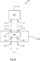
- Fig 2b shows an antenna system 250 where the first 111 and second 112 antenna ports further are arranged to pass a third and a fourth antenna signal, respectively, in addition to the first and the second antenna signal.
- the third and fourth antenna signals have substantially identical envelopes and are derived from a second common antenna signal J 2 which is configured to be substantially orthogonal to the first common antenna signal J 1 .
- the antenna system 250 also comprises a second antenna interface unit 260.
- the second antenna interface unit 260 comprises second 261 and third 262 common ports for passing the first J 1 and also the second J 2 common antenna signal.
- the 180 degree hybrid coupler 220 has first 211 and second 212 coupler ports connected to the first 111 and to the second 112 antenna port, respectively, as well as a summation 221 and a difference 222 port connected to the second 261 and third 262 common ports, respectively, thus selecting the first polarization for one of the first J 1 and the second J 2 common signal, and selecting the second polarization for the other of the first J 1 and second J 2 common signal.
- the first and second common antenna signals are configured to be orthogonal in different ways.
- orthogonal means that the first and second common antenna signals are separable and do not interfere significantly with each other during operation.
- the first J 1 and the second J 2 common signal are orthogonal by separation in frequency, e.g., by means of frequency division duplex, FDD.
- the first J 1 and the second J 2 common signal are orthogonal by separation in time, e.g., by means of time division duplex, TDD.
- the first J 1 and the second J 2 common signal are orthogonal by separation in code, e.g., by means of band spreading by orthogonal codes.
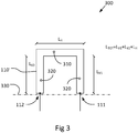
- Fig 3 shows an antenna structure 110' comprising an elongated conductive bridge 310 having a length L H between first and second ends smaller than half of the wavelength corresponding to the highest frequency of the first common antenna signal J 1 .
- the antenna structure 110' further comprises two elongated conductive legs arranged in parallel and having respective lengths L V1 and L V2 between first and second ends smaller than half of the wavelength corresponding to the highest frequency of the first common antenna signal J 1 .
- the legs 320 are attached at first ends to either end of the elongated conductive bridge 310 in right angles with respect to the conductive bridge 310.
- the legs and the bridge together substantially form a conductive U-shape.
- the sum of lengths of the elongated conductive bridge 310 and the two elongated conductive legs 320 is substantially equal to half of the wavelength corresponding to the center frequency of the first common antenna signal J 1 .
- the first 111 antenna port is connected to the second end of one leg, the second 112 antenna port is connected to the second end of the other leg.
- the antenna structure 110' is further arranged to have a ground plane 330 orthogonal to both legs and located approximately at the second end of the legs. Preferably, there is arranged a small separation between the legs 320 and said ground plane 300, as shown in Fig 3 .
- any references to sizes, frequencies, and wavelengths are to be construed as approximate. Thus, at least partial functionality of the antenna system is obtained even if dimensioned slightly outside of given lengths.
- U-shape or U antenna corresponds to the antenna system 300 shown, e.g., in Fig 3
- Pi-shape antenna corresponds to the antenna system 400 shown, e.g., in Fig 4
- the two legs of the antenna structure need not necessarily have the same lengths. In fact, according to some aspects, one leg in the U-shape can have zero length.
- the lengths of the two parallel legs will at times herein be referred to by the common reference symbol L V , instead of L V1 and L V2 .
- An antenna element in the form of a conducting material bent in U shape.
- This U-shape as shown in Fig 3 , consists of two vertical legs each with one open end and the opposite ends interconnected by a horizontal bridge.
- the antenna element will have the open ends meeting ground plane at right angles without actually being in electrical contact with this plane, and the ends are connected to the radar transceiver and fed from this transceiver with the same or with opposite polarity.
- the U element When excited by, e.g., a radar transceiver, the U element will interact with its mirror image in the ground plane. If the length L V is chosen as a quarter of the free space wavelength of the antenna feeding signal, i.e., the common signal, and feeding the two legs of the U with the same polarity, each leg will behave as a monopole. This means that each leg constructively interacts with the ground plane mirror image to forma a half wavelength dipole. Keeping the bridge length L H shorter than half a wavelength means that the bridge will not provide any significant radiation contribution. Thus the radiation produced will be that of the monopole pair and will provide maximum radiation in the direction broadside to the U-shape 110'. There will be no significant radiation in the vertical direction. The electric field will always be substantially parallel to the legs of the U-shape 110'.
- the U-shape 110' constructively interacts with its mirror image to form a magnetic dipole.
- L H should not be too small but say that both L H and L V are on the order of a little less than quarter of a wavelength, then both the L V are close to quarter of a wavelength and 2L V + L H are close to half a wavelength meaning that the antenna has two efficient modes of excitation.
- a magnetic excitation will produce a radiation pattern where radiation is zero on the broadside of the U-shape 110' and is maximum in the pane of the U. The magnetic field will always be parallel to the broadside direction.
- the U-shape antenna shown in Fig 3 is broad-band in the sense that radiation efficiency diminishes when the antenna feed wavelength becomes larger than the resonant condition so far discussed. However, the radiation pattern will not change. When frequencies increase from the resonance condition described the radiation diagram will remain the same until L V approaches half a wavelength of the feed signal or 2L V + L H approaches a full wavelength. It follows that the acceptable limit of top frequency is when L V and L H are both smaller than half of the smallest wavelength of the common antenna signal.
- Typical choices of L V and L H can be 1 m and 0.25 m respectively.
- Fig 4 shows an antenna system 400 where the elongated conductive bridge 310 has been extended by first 410 and second 420 conductive extension units connected at either end of the elongated conductive bridge 310, thus substantially forming a ⁇ -shape.
- the total length of the elongated conductive bridge 310 including extension units 410, 420 is configured to be smaller than the wavelength corresponding to the highest frequency of the common antenna signal J.
- the feature of the elongated conductive bridge 310 including extension units 410, 420 being smaller than the wavelength corresponding to the highest frequency of the common antenna signal advantageously prevents excitation of the bridge due to the bridge being on the order of a wavelength in size.
- ground plane 330 of the antenna structure 110 which ground plane 330 is shown in Figure 4 as a dash-dotted line.
- Fig 5a shows a "U-shape" antenna of the disclosure with electric excitation, i.e., where the first and second antenna signal are set to have the same polarity on first 111 and second 112 antenna ports.
- Fig 5b shows a "U-shape" antenna of the disclosure with magnetic excitation, i.e., where the first and second antenna signal are set to have opposite polarity on first 111 and second 112 antenna ports.
- the antenna structures in Figures 5a/5b are arranged to be fed by a first common signal J connected to the summation port and the difference port of a hybrid coupler, respectively.
- the ground plane 330 of each antenna structure 110' is also shown in Figures 5a and 5b .
- Fig 6a shows a "Pi-shape" antenna with magnetic excitation, i.e., where the first and second antenna signal are set to have opposite polarity on first 111 and second 112 antenna ports. Note that it is only shown the contribution to the radiation pattern from the bide extension, which is added to the diagram of the original U-shape antenna of Figure 5a/5b .
- Fig 6b shows a "Pi-shape" antenna with electric excitation, i.e., where the first and second antenna signal are set to have the same polarity on first 111 and second 112 antenna ports.
- the antenna structures in Figures 6a/6b are also arranged to be fed by a first common signal J connected to the summation port and to the difference port of a hybrid coupler.
- the ground plane 330 of each antenna structure 110' is also shown in Figures 6a and 6b .
- Shown in Figures 5 and 6 are also electric and magnetic field vectors E and H, respectively, of the antenna systems indicating field directions.
- the present antenna system design comprises two modes of vehicle integration, one that exploits the U antenna as is, and the other a modification of the U antenna.
- this modification will be described, with reference to Fig 4 .
- the basic U shape has been altered to a Pi-shape by extending the bridge of the U to a given distance outside either leg.
- the current running through the bridge between the legs will excite a resonance in the extended bridge by which it will start radiating as a horizontal half wavelength dipole.
- the full wavelength excitations of the resulting dipole are pushed to higher frequencies compared to a centrally fed dipole.
- the separated feeds enable the antenna to be longer and thus more efficient without compromising the radiation pattern, which is an advantage of the present technique.
- the ideal antenna illumination pattern for low frequency radar mapping should provide maximum radiation at approximately 30° depressed direction (with respect to the horizon) at right angles to the flight axis and either to the left or right.
- the direction should preferably be selectable.
- the beams are very wide and diffuse meaning that even though the maximum direction may point in another direction it may well be sufficient also at this ideal direction.
- FIGS 7 and 8 illustrate two examples of modes of integration for the U-shape and Pi-shape antennas of the present teaching.
- the aircraft body When integrating the antennas described here on an aircraft, the aircraft body is considered the ground plane.
- the conditions for this assumption to be valid is that the aircraft has dimension of many wavelengths and has good conductivity (if this should turn out not to be the case it must be painted with conductive paint).
- the antennas may not be required that the antennas are installed on a continuous or flat area of the aircraft - also very irregular structures may serve the purpose of a ground plane (a typical case is that the underside of the landing skids of a helicopter may behave as a ground plane).
- Figures 7 and 8 each show an example of an airborne vehicle 710, 810 arranged to carry an antenna system 100, 200, 300, 400 according to the present disclosure.
- the airborne vehicles 710, 810 can, as shown in Fig 7 and Fig 8 , further be arranged to carry a first and a second antenna system 100, 200, 300, 400, i.e., double antenna structures.
- Fig 7 shows a "U-shape" antenna installation on a Hermes 450 un-manned aerial vehicle, UAV.
- UAV un-manned aerial vehicle
- right and left U-shape antennas swing down to a 45° depression with respect to the horizontal plane.
- the right antenna With electric excitation of right hand antenna and magnetic of left hand antenna, the right antenna provides vertical polarization to the left while the left antenna provides horizontal polarization to the left.
- both antennas have radiation nodes to the right, so the requited one-sidedness of the radiation pattern is achieved.
- the length of the elongated bridge is approximately 1.2 meters, and the length of both legs is approximately 1 meter.
- the length of one of the legs is approximately 0 meters, thus substantially forming a single leg antenna system (not shown in Fig 7 ).
- radiation patter of the U-shape antenna can be chosen to obtain horizontal polarization to one side by magnetic excitation of the U-shape antenna at the same side.
- the opposite side antenna is used with electric excitation.
- Fig 8 shows a "Pi" antenna installation on a Bell 212 Huey helicopter.
- the landing skids prevent use of the antenna concept shown in Figure 7 .
- an arrangement is used where the antenna unit unfolds in air from a collapsed position between the landing skids when the helicopter is on ground.
- the right and left antenna are fed with a 90° phase shift and are separated by a quarter of the center frequency wavelength to obtain a one-sided radiation diagram.
- the radiation intensity maximum is directed downwards from the helicopter, i.e., directed towards ground, but since the radiation pattern is very diffuse a significant amount of radiation hits the ground also at relatively shallow depression angles of approximately 30°.
- FIG 8 certain platform designs, in particular helicopters equipped with landing skids, preclude the preferred 45° depressed position of the U-shape antenna arrangement.
- Use of the Pi antenna arrangement can then be suitable.
- the U-shape antenna arrangement can be allowed to swing clear of the ground thus increasing the field of application for the arrangement.
- Figure 7 is an example of where such a mechanical movement is allowed (this case is actually concept where the downward movement of the antennas is actuate by wind forces when the UAV is settling to its normal cruise attitude-these forces works against a spring load keeping the antennas horizontal when on ground).
- the Pi-shape antenna like the U-shape antenna with contra-polar feed has maximum radiation normal to the ground plane, i.e. in the downward direction in Figure 8 .
- the U antenna radiates equally strong to the front and to the rear of the platform resulting in low gain outside the plane of the antenna.
- the Pi antenna radiates less strongly to the front and rear resulting in stronger radiation outside the plane of the antenna and in particular in the required radiation directions between down and broadside.
- the radar signal transmitted though the antenna will strongly couple to the metallic structure of the aircraft itself. This interaction cannot be efficiently handled unless antennas are allowed to geometrically extend from the aircraft by a distance of at least quarter of a wavelength order (herein meter order).
- the length of the elongated conductive bridge 310 with extension units 410, 420 is approximately 3 meters, and the length of each leg is approximately 1.2 meters.
- the antenna system of the present disclosure is adapted to be mounted on an airborne vehicle 710, 810.
- the antenna system 100, 200, 300, 400 is adapted to be mounted on a surface based vehicle.
- the airborne vehicle 710, 810 is arranged as a ground plane of the antenna system 100, 200, 300, 400.
- the antenna system 100, 200, 300, 400 is adapted to be mounted on an airborne vehicle 810 comprising first and second landing skids 820, the antenna system being arranged between the first and second landing skids 820.
- Fig 9 shows a flowchart illustrating a method for selecting an antenna pattern of an antenna system 100.
- the antenna system 100 comprises an antenna structure 110 consisting of a single antenna element having first 111 and second 112 antenna ports arranged to pass a respective first and second antenna signal, the antenna pattern of the antenna structure 110 is arranged to be selectable between a first antenna pattern having a first polarization and a second antenna pattern having a second polarization substantially orthogonal to the first polarization, the method comprising the steps of receiving S0 a first common signal, and deriving S1 the first and second antenna signals from the first common signal, as well as setting S2 the first and second antenna signal to have the same polarity on first 111 and second 112 antenna ports in case the first antenna pattern is selected, and setting S3 the first and second antenna signal to have substantially opposite polarities on first 111 and second 112 antenna ports in case the second antenna pattern is selected.
- the functions or steps noted in the blocks can occur out of the order noted in the operational illustrations.
- two blocks shown in succession can in fact be executed substantially concurrently or the blocks can sometimes be executed in the reverse order, depending upon the functionality/acts involved.
- the functions or steps noted in the blocks can according to some aspects of the disclosure be executed continuously in a loop.
Landscapes
- Engineering & Computer Science (AREA)
- Physics & Mathematics (AREA)
- Remote Sensing (AREA)
- Computer Networks & Wireless Communication (AREA)
- General Physics & Mathematics (AREA)
- Radar, Positioning & Navigation (AREA)
- Signal Processing (AREA)
- Astronomy & Astrophysics (AREA)
- Aviation & Aerospace Engineering (AREA)
- Electromagnetism (AREA)
- Variable-Direction Aerials And Aerial Arrays (AREA)
Claims (12)
- Antennensystem (100) mit einer Antennenstruktur (110), die aus einem einzelnen Antennenelement mit einem ersten (111) und einem zweiten (112) Antennenanschluss besteht, die angeordnet sind, um ein jeweiliges erstes und ein zweites Antennensignal weiterzuleiten, wobei das erste und das zweite Antennensignal so angeordnet sind, dass sie von einem ersten gemeinsamen Antennensignal (J1) abgeleitet werden, und so angeordnet sind, dass sie in der Hüllkurve im Wesentlichen gleich sind, wobei die Antennenstruktur (110) so angeordnet ist, dass sie ein Antennenmuster hat, das zwischen einem ersten Antennenmuster mit einer ersten Polarisation und einem zweiten Antennenmuster mit einer zweiten Polarisation auswählbar ist, die zur ersten Polarisation im Wesentlichen orthogonal ist, wobei das erste Antennenmuster ausgewählt wird, indem das erste und zweite Antennensignal so eingestellt werden, dass sie an einem ersten (111) und zweiten (112) Antennenanschluss die gleiche Polarität haben, das zweite Antennenmuster ausgewählt wird, indem das erste und zweite Antennensignal so eingestellt werden, dass sie an einem ersten (111) und zweiten (112) Antennenanschluss im Wesentlichen entgegengesetzte Polaritäten haben, wobei die Antennenstruktur (110') eine längliche leitende Brücke (310) mit einer Länge (LH) zwischen einem ersten und einem zweiten Ende umfasst, die kleiner ist als die Hälfte der Wellenlänge entsprechend der höchsten Frequenz des ersten gemeinsamen Antennensignals (J1), wobei die Antennenstruktur (110') des Weiteren zwei längliche leitende Schenkel umfasst, die parallel angeordnet sind und jeweilige Längen (Lv1, LV2) zwischen dem ersten und zweiten Ende haben, die kleiner sind als die Hälfte der Wellenlänge entsprechend der höchsten Frequenz des ersten gemeinsamen Antennensignals (J1), wobei die Schenkel (320) an den ersten Schenkelenden an jedem Ende der länglichen leitenden Brücke (310) in rechten Winkeln mit Bezug auf die leitende Brücke (310) angebracht sind, wobei damit im Wesentlichen eine U-Form gebildet wird, wobei die Summe der Längen der länglichen leitenden Brücke (310) und der zwei länglichen leitenden Schenkel (320) im Wesentlichen gleich der Hälfte der Wellenlänge entsprechend der Mittenfrequenz des ersten gemeinsamen Antennensignals (J1) ist, wobei der erste (111) Antennenanschluss mit dem zweiten Ende eines Schenkels verbunden ist, der zweite Antennenanschluss (112) mit dem zweiten Ende des anderen Schenkels verbunden ist, wobei die Antennenstruktur (110') so angeordnet ist, dass sie eine Masseebene (330) hat, die zu beiden Schenkeln orthogonal ist und sich ungefähr an den zweiten Enden der Schenkel befindet, wobei die Antennenstruktur (110') eine Gesamtlänge (LTOT) einschließlich der länglichen leitenden Brücke (310) und beider Schenkel (320) hat, die kleiner ist als die Wellenlänge entsprechend der höchsten Frequenz des ersten gemeinsamen Antennensignals (J1), dadurch gekennzeichnet, dass die längliche leitende Brücke (310) durch eine erste (410) und eine zweite (420) leitende Verlängerungseinheit verlängert wird, die mit jedem Ende der länglichen leitenden Brücke (310) verbunden sind, wobei sie damit im Wesentlichen eine π-Form bilden, wobei die Gesamtlänge der länglichen leitenden Brücke mit Verlängerungseinheiten (410, 420) kleiner ist als die Wellenlänge entsprechend der höchsten Frequenz des ersten gemeinsamen Antennensignals (J1).
- Antennensystem (100) nach Anspruch 1, das entweder in einem Empfängermodus, einem Sendermodus oder einem Sendeempfängermodus angeordnet ist, wobei die Antennenstruktur (110) im Empfängermodus angeordnet ist, um an einem ersten (111) und zweiten (112) Antennenanschluss Antennensignale auszugeben, die über die Antennenstruktur (110) empfangen werden, die Antennenstruktur (110) im Sendermodus angeordnet ist, um am ersten (111) und zweiten (112) Antennenanschluss Antennensignale zu empfangen, die über die Antennenstruktur (120) auszusenden sind, wobei die Antennenstruktur (110) im Sendeempfängermodus angeordnet ist, um am ersten (111) und zweiten (112) Antennenanschluss gleichzeitig Antennensignale auszugeben und zu empfangen.
- Antennensystem (200) nach einem der vorhergehenden Ansprüche, das des Weiteren eine erste Antennenschnittstelleneinheit (210) mit einem 180 Grad-Hybridkoppler (220), eine Schalteinheit (230) und einen ersten gemeinsamen Anschluss (213) zum Weiterleiten des ersten gemeinsamen Antennensignals (J1) umfasst, wobei der 180 Grad-Hybridkoppler (220) einen ersten (211) und einen zweiten (212) Koppleranschluss, die mit dem ersten (111) bzw. dem zweiten (112) Antennenanschluss verbunden sind, sowie einen Summen- (221) und einen Differenzanschluss (222) hat, die mit der Schalteinheit (230) verbunden sind, wobei die Schalteinheit (230) angeordnet ist, um den ersten gemeinsamen Anschluss (213) der Antennenschnittstelleneinheit (210) entweder mit dem Summenanschluss (221) oder dem Differenzanschluss (222) des 180 Grad-Hybridkopplers (220) zu verbinden, wobei damit zwischen dem ersten und dem zweiten Antennenmuster des Antennensystems (200) gewählt wird.
- Antennensystem (250) nach einem der Ansprüche 1 - 2, wobei der erste (111) und der zweite (112) Antennenanschluss des Weiteren angeordnet sind, um ein drittes bzw. ein viertes Antennensignal weiterzuleiten, wobei das dritte und das vierte Antennensignal im Wesentlichen identische Hüllkurven haben und von einem zweiten gemeinsamen Antennensignal (J2) abgeleitet werden, das im Wesentlichen zum ersten gemeinsamen Antennensignal (J1) orthogonal ist, wobei das Antennensystem (250) des Weiteren eine zweite Antennenschnittstelleneinheit (260) umfasst, wobei die zweite Antennenschnittstelleneinheit (260) einen zweiten (261) und einen dritten (262) gemeinsamen Anschluss zum Weiterleiten des ersten (J1) bzw. des zweiten (J2) gemeinsamen Antennensignals sowie einen 180 Grad-Hybridkoppler (220) umfasst, wobei der 180 Grad-Hybridkoppler (220) einen ersten (211) und einen zweiten (212) Koppleranschluss, die mit dem ersten (111) bzw. mit dem zweiten (112) Antennenanschluss verbunden sind, sowie einen Summen- (221) und einen Differenzanschluss (222) hat, die mit dem zweiten (261) bzw. dritten (262) gemeinsamen Anschluss verbunden sind, wobei damit die erste Polarisation für das erste (J1) oder das zweite (J2) gemeinsame Signal ausgewählt wird und die zweite Polarisation für das andere erste (J1) oder zweite (J2) gemeinsame Signal ausgewählt wird.
- Antennensystem (250) nach Anspruch 4, wobei das erste (J1) und das zweite (J2) gemeinsame Signal durch Trennung in Frequenz und/oder Zeit und/oder Code orthogonal sind.
- Antennensystem (100, 200, 400) nach Anspruch 1, wobei die Länge der länglichen leitenden Brücke (310) mit Verlängerungseinheiten (410, 420) etwa 3 Meter und die Länge von jedem Schenkel etwa 1,2 Meter beträgt.
- Antennensystem (100, 200, 300, 400) nach einem der vorhergehenden Ansprüche, das angepasst ist, um an einem Luftfahrzeug (710, 810) montiert zu werden, wobei das Luftfahrzeug (710, 810) als eine Masseebene des Antennensystems (100, 200, 300.400) angeordnet sein kann.
- Antennensystem (100, 200, 300, 400) nach Anspruch 7, das angepasst ist, um an einem Luftfahrzeug (810) mit einer ersten und einer zweiten Landekufe (820) montiert zu werden, wobei das Antennensystem zwischen der ersten und der zweiten Landekufe (820) angeordnet ist.
- Antennensystem (100, 200, 300, 400) nach einem der vorhergehenden Ansprüche, das angepasst ist, um an einem oberflächenbasierten Fahrzeug montiert zu werden.
- Luftfahrzeug (710,810), das angeordnet ist, um das Antennensystem (100, 200, 300, 400) nach einem der Ansprüche 1 - 9 zu befördern.
- Luftfahrzeug (710, 810), das angeordnet ist, um ein erstes und ein zweites Antennensystem (100, 200, 300, 400) nach einem der Ansprüche 1 - 9 zu befördern.
- Verfahren zum Auswählen eines Antennenmusters eines Antennensystems (100), wobei das Antennensystem (100) eine Antennenstruktur (110) umfasst, die aus einem einzelnen Antennenelement mit einem ersten (111) und einem zweiten (112) Antennenanschluss besteht, die angeordnet sind, um ein jeweiliges erstes und ein zweites Antennensignal weiterzuleiten, wobei das Antennenmuster der Antennenstruktur (110) so angeordnet ist, dass es zwischen einem ersten Antennenmuster mit einer ersten Polarisation und einem zweiten Antennenmuster mit einer zweiten Polarisation auswählbar ist, die zu der ersten Polarisation im Wesentlichen orthogonal ist, wobei die Antennenstruktur (110') eine längliche leitende Brücke (310) mit einer Länge (LH) zwischen dem ersten und dem zweiten Ende umfasst, die kleiner ist als die Hälfte der Wellenlänge entsprechend der höchsten Frequenz des ersten gemeinsamen Antennensignals (J1), wobei die Antennenstruktur (110') des Weiteren zwei längliche leitende Schenkel umfasst, die parallel angeordnet sind und jeweilige Längen (LV1, LV2) zwischen dem ersten und dem zweiten Ende haben, die kleiner sind als die Hälfte der Wellenlänge entsprechend der höchsten Frequenz des ersten gemeinsamen Antennensignals (J1), wobei die Schenkel (320) an den ersten Schenkelenden an jedem Ende der länglichen leitenden Brücke (310) in rechten Winkeln mit Bezug auf die leitende Brücke (310) angebracht sind, wobei damit im Wesentlichen eine U-Form gebildet wird, wobei die Summe der Längen der länglichen leitenden Brücke (310) und der zwei länglichen leitenden Schenkel (320) im Wesentlichen gleich der Hälfte der Wellenlänge entsprechend der Mittenfrequenz des ersten gemeinsamen Antennensignals (J1) ist, wobei der erste (111) Antennenanschluss mit dem zweiten Ende von einem Schenkel verbunden ist, der zweite (112) Antennenanschluss mit dem zweiten Ende von dem anderen Schenkel verbunden ist, wobei die Antennenstruktur (110') so angeordnet ist, dass sie eine Masseebene (330) hat, die zu beiden Schenkeln orthogonal ist und sich ungefähr an den zweiten Enden der Schenkel befindet, wobei die Antennenstruktur (110') eine Gesamtlänge (LTOT) einschließlich der länglichen leitenden Brücke (310) und beider Schenkel (320) hat, die kleiner ist als die Wellenlänge entsprechend der höchsten Frequenz des ersten gemeinsamen Antennensignals (J1), wobei die längliche leitende Brücke (310) durch eine erste (410) und eine zweite (420) leitende Verlängerungseinheit verlängert wird, die mit jedem Ende der länglichen leitenden Brücke (310) verbunden sind, wobei damit im Wesentlichen eine π-Form gebildet wird, wobei die Gesamtlänge der länglichen leitenden Brücke mit Verlängerungseinheiten (410, 420) kleiner ist als die Wellenlänge entsprechend der höchsten Frequenz des ersten gemeinsamen Antennensignals (J1), wobei das Verfahren die Schritte umfasst zum- Empfangen (S0) des ersten gemeinsamen Antennensignals,- Ableiten (S1) des ersten und zweiten Antennensignals von dem ersten gemeinsamen Antennensignal,- Einstellen (S2) des ersten und zweiten Antennensignals auf die gleiche Polarität am ersten (111) und zweiten (112) Antennenanschluss in dem Fall, dass das erste Antennenmuster ausgewählt ist,- Einstellen (S3) des ersten und zweiten Antennensignals auf im Wesentlichen entgegengesetzte Polaritäten am ersten (111) und zweiten (112) Antennenanschluss in dem Fall, dass das zweite Antennenmuster ausgewählt ist.
Applications Claiming Priority (1)
| Application Number | Priority Date | Filing Date | Title |
|---|---|---|---|
| PCT/SE2014/050304 WO2015137853A1 (en) | 2014-03-12 | 2014-03-12 | An antenna system for polarization diversity |
Publications (3)
| Publication Number | Publication Date |
|---|---|
| EP3117484A1 EP3117484A1 (de) | 2017-01-18 |
| EP3117484A4 EP3117484A4 (de) | 2017-11-22 |
| EP3117484B1 true EP3117484B1 (de) | 2020-06-03 |
Family
ID=54072154
Family Applications (1)
| Application Number | Title | Priority Date | Filing Date |
|---|---|---|---|
| EP14885561.2A Active EP3117484B1 (de) | 2014-03-12 | 2014-03-12 | Antennensystem für polarisationsdiversität |
Country Status (7)
| Country | Link |
|---|---|
| US (1) | US9618606B2 (de) |
| EP (1) | EP3117484B1 (de) |
| KR (1) | KR102112904B1 (de) |
| BR (1) | BR112016020064B8 (de) |
| ES (1) | ES2813961T3 (de) |
| IL (1) | IL247492B (de) |
| WO (1) | WO2015137853A1 (de) |
Families Citing this family (9)
| Publication number | Priority date | Publication date | Assignee | Title |
|---|---|---|---|---|
| US10396443B2 (en) * | 2015-12-18 | 2019-08-27 | Gopro, Inc. | Integrated antenna in an aerial vehicle |
| KR102093363B1 (ko) * | 2018-04-12 | 2020-03-25 | 주식회사 만도 | 레이더 시스템 및 이를 위한 송신 장치 |
| CN111628274B (zh) * | 2019-02-27 | 2022-10-04 | 华为技术有限公司 | 天线装置及电子设备 |
| WO2020173292A1 (zh) | 2019-02-27 | 2020-09-03 | 华为技术有限公司 | 天线装置及电子设备 |
| EP3787114A1 (de) * | 2019-08-30 | 2021-03-03 | Sivers Ima AB | Antennenvorrichtung |
| US11936119B2 (en) * | 2021-01-29 | 2024-03-19 | KYOCERA AVX Components (San Diego), Inc. | Isolated magnetic dipole antennas having angled edges for improved tuning |
| CN113629408B (zh) * | 2021-08-11 | 2024-09-27 | 维沃移动通信有限公司 | 天线极性切换方法、天线模组和电子设备 |
| DE102022202028A1 (de) * | 2022-02-28 | 2023-08-31 | Volkswagen Aktiengesellschaft | Radarsensorvorrichtung für ein Fahrzeug, sowie Radarsystem mit einer Radarsensorvorrichtung und Fahrzeug mit einem Radarsystem |
| US20250192448A1 (en) * | 2022-03-02 | 2025-06-12 | Ruckus Ip Holdings Llc | Access points that generate antenna beams having optimized radiation patterns and polarizations and related methods |
Family Cites Families (22)
| Publication number | Priority date | Publication date | Assignee | Title |
|---|---|---|---|---|
| US4006481A (en) * | 1975-12-10 | 1977-02-01 | The Ohio State University | Underground, time domain, electromagnetic reflectometry for digging apparatus |
| GB8426245D0 (en) * | 1984-10-17 | 1984-11-21 | British Gas Corp | Microwave reflection survey equipment |
| GB8607705D0 (en) * | 1986-03-27 | 1986-04-30 | British Gas Corp | Signal processing |
| US4733245A (en) * | 1986-06-23 | 1988-03-22 | Ball Corporation | Cavity-backed slot antenna |
| US5568159A (en) * | 1994-05-12 | 1996-10-22 | Mcdonnell Douglas Corporation | Flared notch slot antenna |
| US5977916A (en) * | 1997-05-09 | 1999-11-02 | Motorola, Inc. | Difference drive diversity antenna structure and method |
| US6429802B1 (en) * | 1998-12-08 | 2002-08-06 | Geophysical Survey Systems | Determining the condition of a concrete structure using electromagnetic signals |
| US7450052B2 (en) * | 1999-05-25 | 2008-11-11 | The Macaleese Companies, Inc. | Object detection method and apparatus |
| US6982666B2 (en) * | 2001-06-08 | 2006-01-03 | The United States Of America As Represented By The Secretary Of The Navy | Three-dimensional synthetic aperture radar for mine detection and other uses |
| AU2002950196A0 (en) * | 2002-07-11 | 2002-09-12 | Commonwealth Scientific And Industrial Research Organisation | Real-time, cross-correlating millimetre-wave imaging system |
| NO20025295A (no) * | 2002-11-05 | 2004-03-22 | 3D Radar As | Antennesystem for en georadar |
| US7528762B2 (en) * | 2005-03-31 | 2009-05-05 | Southwest Research Institute | Signal processing methods for ground penetrating radar from elevated platforms |
| KR100713155B1 (ko) * | 2005-07-13 | 2007-05-02 | 삼성전자주식회사 | 단일 원형편파안테나를 구비한 레이더 시스템 |
| US7292195B2 (en) * | 2005-07-26 | 2007-11-06 | Motorola, Inc. | Energy diversity antenna and system |
| IL176411A0 (en) * | 2006-06-19 | 2007-07-04 | Ariel University Res And Dev C | Hand-held device and method for detecting concealed weapons and hidden objects |
| US7994999B2 (en) * | 2007-11-30 | 2011-08-09 | Harada Industry Of America, Inc. | Microstrip antenna |
| JPWO2009072189A1 (ja) * | 2007-12-04 | 2011-04-21 | パナソニック株式会社 | アンテナ装置及び通信装置 |
| DE102007062997A1 (de) * | 2007-12-21 | 2009-06-25 | Robert Bosch Gmbh | Ortungsgerät |
| ES2797529T3 (es) * | 2012-12-17 | 2020-12-02 | Saab Ab | Radar de formación de imágenes subsuperficie |
| US9692134B2 (en) * | 2013-08-09 | 2017-06-27 | Harris Corporation | Broadband dual polarization omni-directional antenna with dual conductive antenna bodies and associated methods |
| US9293812B2 (en) * | 2013-11-06 | 2016-03-22 | Delphi Technologies, Inc. | Radar antenna assembly |
| US9843103B2 (en) * | 2014-03-26 | 2017-12-12 | Elwha Llc | Methods and apparatus for controlling a surface scattering antenna array |
-
2014
- 2014-03-12 EP EP14885561.2A patent/EP3117484B1/de active Active
- 2014-03-12 BR BR112016020064A patent/BR112016020064B8/pt active Search and Examination
- 2014-03-12 ES ES14885561T patent/ES2813961T3/es active Active
- 2014-03-12 KR KR1020167028419A patent/KR102112904B1/ko active Active
- 2014-03-12 WO PCT/SE2014/050304 patent/WO2015137853A1/en not_active Ceased
- 2014-03-12 US US15/124,885 patent/US9618606B2/en active Active
-
2016
- 2016-08-25 IL IL247492A patent/IL247492B/en active IP Right Grant
Non-Patent Citations (1)
| Title |
|---|
| None * |
Also Published As
| Publication number | Publication date |
|---|---|
| IL247492A0 (en) | 2016-11-30 |
| US20170016978A1 (en) | 2017-01-19 |
| US9618606B2 (en) | 2017-04-11 |
| ES2813961T3 (es) | 2021-03-25 |
| EP3117484A4 (de) | 2017-11-22 |
| WO2015137853A1 (en) | 2015-09-17 |
| BR112016020064A8 (pt) | 2021-06-29 |
| KR20160132461A (ko) | 2016-11-18 |
| KR102112904B1 (ko) | 2020-05-19 |
| BR112016020064A2 (pt) | 2017-08-15 |
| BR112016020064B1 (pt) | 2022-10-18 |
| BR112016020064B8 (pt) | 2022-11-16 |
| EP3117484A1 (de) | 2017-01-18 |
| IL247492B (en) | 2021-02-28 |
Similar Documents
| Publication | Publication Date | Title |
|---|---|---|
| EP3117484B1 (de) | Antennensystem für polarisationsdiversität | |
| US7071879B2 (en) | Dielectric-resonator array antenna system | |
| US6252553B1 (en) | Multi-mode patch antenna system and method of forming and steering a spatial null | |
| US5940036A (en) | Broadband circularly polarized dielectric resonator antenna | |
| CN107615588A (zh) | 具有外围寄生单极子圆形阵列的贴片天线 | |
| WO2016010717A1 (en) | Antenna system | |
| CA2752704A1 (en) | Planar slot antenna having multi-polarization capability and associated methods | |
| US20150288064A1 (en) | Switchable Antenna | |
| KR102381296B1 (ko) | Rfid 리더 안테나 | |
| CN105140642B (zh) | 圆极化天线 | |
| KR101843305B1 (ko) | 광대역 캐비티 백 안테나 | |
| US8860617B1 (en) | Multiband embedded antenna | |
| Dweik et al. | A planar antenna array with integrated feed network for UAV applications | |
| WO2023200664A1 (en) | Compact covert fractal antennae | |
| Patel et al. | Utilization of higher-mode resonance in broadening the E-plane HPBW of printed antenna for automotive radar application | |
| EP4027452B1 (de) | Mehrbandige integrierte antennenarrays für flugzeuge mit vertikalem auftrieb und nvis mit multipolarisation | |
| JPH05299925A (ja) | 移動体アンテナ装置 | |
| Mathew | A three element Yagi Uda antenna for RFID systems | |
| Buttazzoni | Reconfigurable antenna arrays with phase-only control in the presence of near-field nulls | |
| JP6456258B2 (ja) | アンテナ装置 | |
| Gao et al. | Low-cost smart antennas for advanced wireless systems | |
| Nomoto et al. | Low-profile unidirectional pattern antenna composed of two gate-shaped elements | |
| Pal et al. | Phased array system consisting of unit pattern reconfigurable Square Loop Antennas | |
| Purnomo et al. | The influence of hole-truncated to characteristic performance of the equilateral triangular antenna for mobile satellite communications | |
| Tahseen et al. | Bandwidth enhancement in Ka-Band circularly polarized reflectarray using stacked cross-bowtie elements |
Legal Events
| Date | Code | Title | Description |
|---|---|---|---|
| PUAI | Public reference made under article 153(3) epc to a published international application that has entered the european phase |
Free format text: ORIGINAL CODE: 0009012 |
|
| STAA | Information on the status of an ep patent application or granted ep patent |
Free format text: STATUS: REQUEST FOR EXAMINATION WAS MADE |
|
| 17P | Request for examination filed |
Effective date: 20160825 |
|
| AK | Designated contracting states |
Kind code of ref document: A1 Designated state(s): AL AT BE BG CH CY CZ DE DK EE ES FI FR GB GR HR HU IE IS IT LI LT LU LV MC MK MT NL NO PL PT RO RS SE SI SK SM TR |
|
| AX | Request for extension of the european patent |
Extension state: BA ME |
|
| DAX | Request for extension of the european patent (deleted) | ||
| A4 | Supplementary search report drawn up and despatched |
Effective date: 20171019 |
|
| RIC1 | Information provided on ipc code assigned before grant |
Ipc: G01S 7/02 20060101ALI20171013BHEP Ipc: H04B 7/02 20170101ALI20171013BHEP Ipc: H01Q 7/00 20060101ALI20171013BHEP Ipc: H01Q 1/28 20060101AFI20171013BHEP Ipc: H01Q 11/14 20060101ALI20171013BHEP Ipc: G01S 13/88 20060101ALI20171013BHEP Ipc: G01S 7/03 20060101ALI20171013BHEP |
|
| GRAP | Despatch of communication of intention to grant a patent |
Free format text: ORIGINAL CODE: EPIDOSNIGR1 |
|
| STAA | Information on the status of an ep patent application or granted ep patent |
Free format text: STATUS: GRANT OF PATENT IS INTENDED |
|
| INTG | Intention to grant announced |
Effective date: 20200109 |
|
| GRAS | Grant fee paid |
Free format text: ORIGINAL CODE: EPIDOSNIGR3 |
|
| GRAA | (expected) grant |
Free format text: ORIGINAL CODE: 0009210 |
|
| STAA | Information on the status of an ep patent application or granted ep patent |
Free format text: STATUS: THE PATENT HAS BEEN GRANTED |
|
| AK | Designated contracting states |
Kind code of ref document: B1 Designated state(s): AL AT BE BG CH CY CZ DE DK EE ES FI FR GB GR HR HU IE IS IT LI LT LU LV MC MK MT NL NO PL PT RO RS SE SI SK SM TR |
|
| REG | Reference to a national code |
Ref country code: GB Ref legal event code: FG4D |
|
| REG | Reference to a national code |
Ref country code: CH Ref legal event code: EP Ref country code: AT Ref legal event code: REF Ref document number: 1277990 Country of ref document: AT Kind code of ref document: T Effective date: 20200615 |
|
| REG | Reference to a national code |
Ref country code: DE Ref legal event code: R096 Ref document number: 602014066368 Country of ref document: DE |
|
| REG | Reference to a national code |
Ref country code: NL Ref legal event code: FP |
|
| REG | Reference to a national code |
Ref country code: LT Ref legal event code: MG4D |
|
| PG25 | Lapsed in a contracting state [announced via postgrant information from national office to epo] |
Ref country code: FI Free format text: LAPSE BECAUSE OF FAILURE TO SUBMIT A TRANSLATION OF THE DESCRIPTION OR TO PAY THE FEE WITHIN THE PRESCRIBED TIME-LIMIT Effective date: 20200603 Ref country code: SE Free format text: LAPSE BECAUSE OF FAILURE TO SUBMIT A TRANSLATION OF THE DESCRIPTION OR TO PAY THE FEE WITHIN THE PRESCRIBED TIME-LIMIT Effective date: 20200603 Ref country code: LT Free format text: LAPSE BECAUSE OF FAILURE TO SUBMIT A TRANSLATION OF THE DESCRIPTION OR TO PAY THE FEE WITHIN THE PRESCRIBED TIME-LIMIT Effective date: 20200603 Ref country code: GR Free format text: LAPSE BECAUSE OF FAILURE TO SUBMIT A TRANSLATION OF THE DESCRIPTION OR TO PAY THE FEE WITHIN THE PRESCRIBED TIME-LIMIT Effective date: 20200904 Ref country code: NO Free format text: LAPSE BECAUSE OF FAILURE TO SUBMIT A TRANSLATION OF THE DESCRIPTION OR TO PAY THE FEE WITHIN THE PRESCRIBED TIME-LIMIT Effective date: 20200903 |
|
| PG25 | Lapsed in a contracting state [announced via postgrant information from national office to epo] |
Ref country code: BG Free format text: LAPSE BECAUSE OF FAILURE TO SUBMIT A TRANSLATION OF THE DESCRIPTION OR TO PAY THE FEE WITHIN THE PRESCRIBED TIME-LIMIT Effective date: 20200903 Ref country code: LV Free format text: LAPSE BECAUSE OF FAILURE TO SUBMIT A TRANSLATION OF THE DESCRIPTION OR TO PAY THE FEE WITHIN THE PRESCRIBED TIME-LIMIT Effective date: 20200603 Ref country code: RS Free format text: LAPSE BECAUSE OF FAILURE TO SUBMIT A TRANSLATION OF THE DESCRIPTION OR TO PAY THE FEE WITHIN THE PRESCRIBED TIME-LIMIT Effective date: 20200603 Ref country code: HR Free format text: LAPSE BECAUSE OF FAILURE TO SUBMIT A TRANSLATION OF THE DESCRIPTION OR TO PAY THE FEE WITHIN THE PRESCRIBED TIME-LIMIT Effective date: 20200603 |
|
| REG | Reference to a national code |
Ref country code: AT Ref legal event code: MK05 Ref document number: 1277990 Country of ref document: AT Kind code of ref document: T Effective date: 20200603 |
|
| PG25 | Lapsed in a contracting state [announced via postgrant information from national office to epo] |
Ref country code: AL Free format text: LAPSE BECAUSE OF FAILURE TO SUBMIT A TRANSLATION OF THE DESCRIPTION OR TO PAY THE FEE WITHIN THE PRESCRIBED TIME-LIMIT Effective date: 20200603 |
|
| PG25 | Lapsed in a contracting state [announced via postgrant information from national office to epo] |
Ref country code: AT Free format text: LAPSE BECAUSE OF FAILURE TO SUBMIT A TRANSLATION OF THE DESCRIPTION OR TO PAY THE FEE WITHIN THE PRESCRIBED TIME-LIMIT Effective date: 20200603 Ref country code: SM Free format text: LAPSE BECAUSE OF FAILURE TO SUBMIT A TRANSLATION OF THE DESCRIPTION OR TO PAY THE FEE WITHIN THE PRESCRIBED TIME-LIMIT Effective date: 20200603 Ref country code: EE Free format text: LAPSE BECAUSE OF FAILURE TO SUBMIT A TRANSLATION OF THE DESCRIPTION OR TO PAY THE FEE WITHIN THE PRESCRIBED TIME-LIMIT Effective date: 20200603 Ref country code: CZ Free format text: LAPSE BECAUSE OF FAILURE TO SUBMIT A TRANSLATION OF THE DESCRIPTION OR TO PAY THE FEE WITHIN THE PRESCRIBED TIME-LIMIT Effective date: 20200603 Ref country code: RO Free format text: LAPSE BECAUSE OF FAILURE TO SUBMIT A TRANSLATION OF THE DESCRIPTION OR TO PAY THE FEE WITHIN THE PRESCRIBED TIME-LIMIT Effective date: 20200603 Ref country code: PT Free format text: LAPSE BECAUSE OF FAILURE TO SUBMIT A TRANSLATION OF THE DESCRIPTION OR TO PAY THE FEE WITHIN THE PRESCRIBED TIME-LIMIT Effective date: 20201006 |
|
| PG25 | Lapsed in a contracting state [announced via postgrant information from national office to epo] |
Ref country code: PL Free format text: LAPSE BECAUSE OF FAILURE TO SUBMIT A TRANSLATION OF THE DESCRIPTION OR TO PAY THE FEE WITHIN THE PRESCRIBED TIME-LIMIT Effective date: 20200603 Ref country code: SK Free format text: LAPSE BECAUSE OF FAILURE TO SUBMIT A TRANSLATION OF THE DESCRIPTION OR TO PAY THE FEE WITHIN THE PRESCRIBED TIME-LIMIT Effective date: 20200603 Ref country code: IS Free format text: LAPSE BECAUSE OF FAILURE TO SUBMIT A TRANSLATION OF THE DESCRIPTION OR TO PAY THE FEE WITHIN THE PRESCRIBED TIME-LIMIT Effective date: 20201003 |
|
| REG | Reference to a national code |
Ref country code: DE Ref legal event code: R097 Ref document number: 602014066368 Country of ref document: DE |
|
| REG | Reference to a national code |
Ref country code: ES Ref legal event code: FG2A Ref document number: 2813961 Country of ref document: ES Kind code of ref document: T3 Effective date: 20210325 |
|
| PLBE | No opposition filed within time limit |
Free format text: ORIGINAL CODE: 0009261 |
|
| STAA | Information on the status of an ep patent application or granted ep patent |
Free format text: STATUS: NO OPPOSITION FILED WITHIN TIME LIMIT |
|
| PG25 | Lapsed in a contracting state [announced via postgrant information from national office to epo] |
Ref country code: DK Free format text: LAPSE BECAUSE OF FAILURE TO SUBMIT A TRANSLATION OF THE DESCRIPTION OR TO PAY THE FEE WITHIN THE PRESCRIBED TIME-LIMIT Effective date: 20200603 |
|
| 26N | No opposition filed |
Effective date: 20210304 |
|
| PG25 | Lapsed in a contracting state [announced via postgrant information from national office to epo] |
Ref country code: SI Free format text: LAPSE BECAUSE OF FAILURE TO SUBMIT A TRANSLATION OF THE DESCRIPTION OR TO PAY THE FEE WITHIN THE PRESCRIBED TIME-LIMIT Effective date: 20200603 |
|
| PG25 | Lapsed in a contracting state [announced via postgrant information from national office to epo] |
Ref country code: MC Free format text: LAPSE BECAUSE OF FAILURE TO SUBMIT A TRANSLATION OF THE DESCRIPTION OR TO PAY THE FEE WITHIN THE PRESCRIBED TIME-LIMIT Effective date: 20200603 |
|
| REG | Reference to a national code |
Ref country code: CH Ref legal event code: PL |
|
| REG | Reference to a national code |
Ref country code: BE Ref legal event code: MM Effective date: 20210331 |
|
| PG25 | Lapsed in a contracting state [announced via postgrant information from national office to epo] |
Ref country code: IE Free format text: LAPSE BECAUSE OF NON-PAYMENT OF DUE FEES Effective date: 20210312 Ref country code: LI Free format text: LAPSE BECAUSE OF NON-PAYMENT OF DUE FEES Effective date: 20210331 Ref country code: LU Free format text: LAPSE BECAUSE OF NON-PAYMENT OF DUE FEES Effective date: 20210312 Ref country code: CH Free format text: LAPSE BECAUSE OF NON-PAYMENT OF DUE FEES Effective date: 20210331 |
|
| PG25 | Lapsed in a contracting state [announced via postgrant information from national office to epo] |
Ref country code: BE Free format text: LAPSE BECAUSE OF NON-PAYMENT OF DUE FEES Effective date: 20210331 |
|
| PG25 | Lapsed in a contracting state [announced via postgrant information from national office to epo] |
Ref country code: HU Free format text: LAPSE BECAUSE OF FAILURE TO SUBMIT A TRANSLATION OF THE DESCRIPTION OR TO PAY THE FEE WITHIN THE PRESCRIBED TIME-LIMIT; INVALID AB INITIO Effective date: 20140312 |
|
| PG25 | Lapsed in a contracting state [announced via postgrant information from national office to epo] |
Ref country code: CY Free format text: LAPSE BECAUSE OF FAILURE TO SUBMIT A TRANSLATION OF THE DESCRIPTION OR TO PAY THE FEE WITHIN THE PRESCRIBED TIME-LIMIT Effective date: 20200603 |
|
| PG25 | Lapsed in a contracting state [announced via postgrant information from national office to epo] |
Ref country code: MK Free format text: LAPSE BECAUSE OF FAILURE TO SUBMIT A TRANSLATION OF THE DESCRIPTION OR TO PAY THE FEE WITHIN THE PRESCRIBED TIME-LIMIT Effective date: 20200603 |
|
| PG25 | Lapsed in a contracting state [announced via postgrant information from national office to epo] |
Ref country code: MT Free format text: LAPSE BECAUSE OF FAILURE TO SUBMIT A TRANSLATION OF THE DESCRIPTION OR TO PAY THE FEE WITHIN THE PRESCRIBED TIME-LIMIT Effective date: 20200603 |
|
| PGFP | Annual fee paid to national office [announced via postgrant information from national office to epo] |
Ref country code: ES Payment date: 20250523 Year of fee payment: 12 |
|
| PG25 | Lapsed in a contracting state [announced via postgrant information from national office to epo] |
Ref country code: TR Free format text: LAPSE BECAUSE OF FAILURE TO SUBMIT A TRANSLATION OF THE DESCRIPTION OR TO PAY THE FEE WITHIN THE PRESCRIBED TIME-LIMIT Effective date: 20200603 |
|
| PGFP | Annual fee paid to national office [announced via postgrant information from national office to epo] |
Ref country code: NL Payment date: 20260123 Year of fee payment: 13 |
|
| PGFP | Annual fee paid to national office [announced via postgrant information from national office to epo] |
Ref country code: GB Payment date: 20260119 Year of fee payment: 13 |
|
| PGFP | Annual fee paid to national office [announced via postgrant information from national office to epo] |
Ref country code: DE Payment date: 20260216 Year of fee payment: 13 |
|
| PGFP | Annual fee paid to national office [announced via postgrant information from national office to epo] |
Ref country code: IT Payment date: 20260218 Year of fee payment: 13 |
|
| PGFP | Annual fee paid to national office [announced via postgrant information from national office to epo] |
Ref country code: FR Payment date: 20260120 Year of fee payment: 13 |