EP3117776B1 - Ultraschallkatheter mit temperaturerfassung am distalen ende - Google Patents
Ultraschallkatheter mit temperaturerfassung am distalen ende Download PDFInfo
- Publication number
- EP3117776B1 EP3117776B1 EP16182768.8A EP16182768A EP3117776B1 EP 3117776 B1 EP3117776 B1 EP 3117776B1 EP 16182768 A EP16182768 A EP 16182768A EP 3117776 B1 EP3117776 B1 EP 3117776B1
- Authority
- EP
- European Patent Office
- Prior art keywords
- transmission element
- distal end
- temperature
- path length
- acoustic
- Prior art date
- Legal status (The legal status is an assumption and is not a legal conclusion. Google has not performed a legal analysis and makes no representation as to the accuracy of the status listed.)
- Not-in-force
Links
Images


Classifications
-
- A—HUMAN NECESSITIES
- A61—MEDICAL OR VETERINARY SCIENCE; HYGIENE
- A61B—DIAGNOSIS; SURGERY; IDENTIFICATION
- A61B8/00—Diagnosis using ultrasonic, sonic or infrasonic waves
- A61B8/08—Clinical applications
-
- A—HUMAN NECESSITIES
- A61—MEDICAL OR VETERINARY SCIENCE; HYGIENE
- A61B—DIAGNOSIS; SURGERY; IDENTIFICATION
- A61B18/00—Surgical instruments, devices or methods for transferring non-mechanical forms of energy to or from the body
- A61B18/04—Surgical instruments, devices or methods for transferring non-mechanical forms of energy to or from the body by heating
- A61B18/12—Surgical instruments, devices or methods for transferring non-mechanical forms of energy to or from the body by heating by passing a current through the tissue to be heated, e.g. high-frequency current
- A61B18/14—Probes or electrodes therefor
- A61B18/1492—Probes or electrodes therefor having a flexible, catheter-like structure, e.g. for heart ablation
-
- A—HUMAN NECESSITIES
- A61—MEDICAL OR VETERINARY SCIENCE; HYGIENE
- A61B—DIAGNOSIS; SURGERY; IDENTIFICATION
- A61B8/00—Diagnosis using ultrasonic, sonic or infrasonic waves
- A61B8/12—Diagnosis using ultrasonic, sonic or infrasonic waves in body cavities or body tracts, e.g. by using catheters
-
- A—HUMAN NECESSITIES
- A61—MEDICAL OR VETERINARY SCIENCE; HYGIENE
- A61B—DIAGNOSIS; SURGERY; IDENTIFICATION
- A61B8/00—Diagnosis using ultrasonic, sonic or infrasonic waves
- A61B8/44—Constructional features of the ultrasonic, sonic or infrasonic diagnostic device
- A61B8/4444—Constructional features of the ultrasonic, sonic or infrasonic diagnostic device related to the probe
- A61B8/445—Details of catheter construction
-
- A—HUMAN NECESSITIES
- A61—MEDICAL OR VETERINARY SCIENCE; HYGIENE
- A61B—DIAGNOSIS; SURGERY; IDENTIFICATION
- A61B8/00—Diagnosis using ultrasonic, sonic or infrasonic waves
- A61B8/44—Constructional features of the ultrasonic, sonic or infrasonic diagnostic device
- A61B8/4483—Constructional features of the ultrasonic, sonic or infrasonic diagnostic device characterised by features of the ultrasound transducer
-
- A—HUMAN NECESSITIES
- A61—MEDICAL OR VETERINARY SCIENCE; HYGIENE
- A61B—DIAGNOSIS; SURGERY; IDENTIFICATION
- A61B8/00—Diagnosis using ultrasonic, sonic or infrasonic waves
- A61B8/54—Control of the diagnostic device
- A61B8/546—Control of the diagnostic device involving monitoring or regulation of device temperature
-
- G—PHYSICS
- G01—MEASURING; TESTING
- G01K—MEASURING TEMPERATURE; MEASURING QUANTITY OF HEAT; THERMALLY-SENSITIVE ELEMENTS NOT OTHERWISE PROVIDED FOR
- G01K11/00—Measuring temperature based upon physical or chemical changes not covered by groups G01K3/00, G01K5/00, G01K7/00 or G01K9/00
- G01K11/22—Measuring temperature based upon physical or chemical changes not covered by groups G01K3/00, G01K5/00, G01K7/00 or G01K9/00 using measurement of acoustic effects
- G01K11/24—Measuring temperature based upon physical or chemical changes not covered by groups G01K3/00, G01K5/00, G01K7/00 or G01K9/00 using measurement of acoustic effects of the velocity of propagation of sound
-
- G—PHYSICS
- G01—MEASURING; TESTING
- G01K—MEASURING TEMPERATURE; MEASURING QUANTITY OF HEAT; THERMALLY-SENSITIVE ELEMENTS NOT OTHERWISE PROVIDED FOR
- G01K13/00—Thermometers specially adapted for specific purposes
- G01K13/20—Clinical contact thermometers for use with humans or animals
-
- A—HUMAN NECESSITIES
- A61—MEDICAL OR VETERINARY SCIENCE; HYGIENE
- A61B—DIAGNOSIS; SURGERY; IDENTIFICATION
- A61B18/00—Surgical instruments, devices or methods for transferring non-mechanical forms of energy to or from the body
- A61B18/04—Surgical instruments, devices or methods for transferring non-mechanical forms of energy to or from the body by heating
- A61B18/12—Surgical instruments, devices or methods for transferring non-mechanical forms of energy to or from the body by heating by passing a current through the tissue to be heated, e.g. high-frequency current
- A61B18/1206—Generators therefor
-
- A—HUMAN NECESSITIES
- A61—MEDICAL OR VETERINARY SCIENCE; HYGIENE
- A61B—DIAGNOSIS; SURGERY; IDENTIFICATION
- A61B18/00—Surgical instruments, devices or methods for transferring non-mechanical forms of energy to or from the body
- A61B2018/00636—Sensing and controlling the application of energy
- A61B2018/00696—Controlled or regulated parameters
- A61B2018/00702—Power or energy
-
- A—HUMAN NECESSITIES
- A61—MEDICAL OR VETERINARY SCIENCE; HYGIENE
- A61B—DIAGNOSIS; SURGERY; IDENTIFICATION
- A61B18/00—Surgical instruments, devices or methods for transferring non-mechanical forms of energy to or from the body
- A61B2018/00636—Sensing and controlling the application of energy
- A61B2018/00773—Sensed parameters
- A61B2018/00791—Temperature
-
- A—HUMAN NECESSITIES
- A61—MEDICAL OR VETERINARY SCIENCE; HYGIENE
- A61B—DIAGNOSIS; SURGERY; IDENTIFICATION
- A61B90/00—Instruments, implements or accessories specially adapted for surgery or diagnosis and not covered by any of the groups A61B1/00 - A61B50/00, e.g. for luxation treatment or for protecting wound edges
- A61B90/36—Image-producing devices or illumination devices not otherwise provided for
- A61B90/37—Surgical systems with images on a monitor during operation
- A61B2090/378—Surgical systems with images on a monitor during operation using ultrasound
- A61B2090/3782—Surgical systems with images on a monitor during operation using ultrasound transmitter or receiver in catheter or minimal invasive instrument
-
- A—HUMAN NECESSITIES
- A61—MEDICAL OR VETERINARY SCIENCE; HYGIENE
- A61B—DIAGNOSIS; SURGERY; IDENTIFICATION
- A61B8/00—Diagnosis using ultrasonic, sonic or infrasonic waves
- A61B8/08—Clinical applications
- A61B8/0883—Clinical applications for diagnosis of the heart
-
- A—HUMAN NECESSITIES
- A61—MEDICAL OR VETERINARY SCIENCE; HYGIENE
- A61N—ELECTROTHERAPY; MAGNETOTHERAPY; RADIATION THERAPY; ULTRASOUND THERAPY
- A61N7/00—Ultrasound therapy
- A61N2007/0078—Ultrasound therapy with multiple treatment transducers
-
- G—PHYSICS
- G01—MEASURING; TESTING
- G01K—MEASURING TEMPERATURE; MEASURING QUANTITY OF HEAT; THERMALLY-SENSITIVE ELEMENTS NOT OTHERWISE PROVIDED FOR
- G01K2217/00—Temperature measurement using electric or magnetic components already present in the system to be measured
Definitions
- the invention relates to an ultrasound catheter, capable of detecting the temperature at its distal end.
- cardiac arrhythmias may be treated by various catheter-based ablation techniques to destroy arrhythmogenic parts of the cardiac tissue.
- RF radio-frequency
- HIFU high intensity focused ultrasound
- cryo-ablations of the tissue are commonly used.
- the probe temperature reflects the tissue temperature.
- the ablation profile may be controlled by the temperature, and direct thermal feedback may be used to titrate the ablation energy.
- the US patent application no. 2006/0030844 A1 discloses to use a transparent electrode suitable for radiofrequency (RF) ablation of tissue. It is disclosed to cover a transparent material with a conductive coating so that the conductive coating is capable of delivering RF energy to the tissue, while the combined system of transparent material and coating is transparent to radiation from various imaging modalities. Different surface temperature means for measuring the temperature are disclosed. For example, it is disclosed to place a thermocouple on the electrode surface.
- thermocouple on the electrode surface however puts the thermocouple in the field of view. While this may be acceptable for some application, this may not be the case for all applications. Moreover, there is still a need in the art for alternative or improved temperature sensing solutions, suitable for use in connection with catheter-based surgery.
- US 2009/0030312 A1 discloses an ultrasonic imaging catheter comprising theraphy electrodes of thin layer of metallic material supported by a sythetic material capable of withstanding the high temepratures generated by the therapy electrodes, and which electrodes are effectively transparent to the ultrasound, wherein the electrodes are separated in order to be operable individually and which collectively cover 50%-90% of the cross sectional area in front of ultrasound array.
- US 2006/0241426 A1 discloses an ultrasound diagnostic apparatus for contacting a test subject with a window, the apparatus comprising a sonic element and a window separated by oil, wherein the surface of the window is detected from the measured sound velocity of the window.
- thermocouple-based temperature sensing solutions may not be suitable for use in connection with medical devices comprising integrated ultrasound monitoring in the forward looking geometry, since the positioning of the thermocouple may be in the field of view of the acoustic radiation. Consequently it would be advantageous to achieve a temperature sensing solution which is suitable for integration with medical devices comprising integrated ultrasound transducers.
- the invention preferably seeks to mitigate, alleviate or eliminate one or more of the above mentioned disadvantages singly or in any combination.
- an ultrasound catheter device comprising:
- the temperature of the ablation electrode and the tissue increases and as a result, the acoustical path length through the transparent ablation electrode increases too.
- the acoustic path length can be monitored. Since during use, the transmission element will be in close contact with tissue under investigation or treatment, this temperature will be the same as, or close to, the temperature of the tissue.
- the temperature at the distal end of the medical ultrasound device, and hence the temperature of the tissue under investigation or treatment can be determined.
- the one or more ultrasound transducers are capable of generating acoustic radiation suitable for monitoring a region of interest simultaneously with, concurrently with or together with detecting the acoustic path length through the transmission element.
- key elements to perform the temperature detection are elements which also may be used for other purposes, and a separate sensor is not needed.
- the ultrasound transducer(s) maybe used for monitoring purposes and a transmission element is always needed in order to couple the acoustic radiation out of the medical device. A compact and cost-effective medical device is therefore provided.
- a temperature sensor may be provided which does not shadow the acoustic radiation.
- monitoring is to be construed broadly. It includes both 1D monitoring, i.e. detecting reflected intensities along the line of sight as well as 2D imaging where an array of transducers are applied to generate a 2D image. In principle also 3D imaging and time resolved imaging may be obtained.
- 1D monitoring i.e. detecting reflected intensities along the line of sight
- 2D imaging where an array of transducers are applied to generate a 2D image.
- 3D imaging and time resolved imaging may be obtained.
- catheter-based monitoring it is normal to use 1D or 2D monitoring due to space constraints in the distal end region, i.e. in the tip region.
- the transmission element should be substantially transparent to acoustic radiation.
- a material with a transparency to acoustic radiation above 50% may be used, such as above 60%, 70%, 80%, 90%, or even above 95%.
- the transmission element comprises a polymer-based body, covered with an electrode formed by thin conducting layer. Acoustic radiation is transmitted substantially unaffected by the presence of a metal layer with a thickness below 500 nanometers, such as below 250 nanometers, such as with a thickness of 150 nanometers.
- the electrode may be in the form of a mesh or other open structures. An electrode in the form of a mesh, with a central aperture or even in the form of a band or ring, may allow radiation to pass, and still be able to work as an RF-electrode.
- the acoustic path length is detected based on detecting reflected acoustic radiation from a surface of the backside of the transmission element and a surface of the front-side of the transmission element
- the acoustic path length may be detected based on detecting a separation of reflection peaks obtained from the surface of the backside of the transmission element and the surface of the front-side of the transmission element.
- the detection of the acoustic path length may be based on a detection of the time of flight, and changes in time of flight, of radiation emitted from the transducer, reflected from a surface of the transmission element, and detected again by the transducer.
- the polymer-based body has a change of velocity of the acoustic radiation larger than 0.1% per degree Celsius or larger, such as 0.25% per degree Celsius or even larger.
- the temperature at the distal end is determined based on a look-up table or a functional relationship between a parameter related to the acoustic path length and the temperature at the distal end.
- a look-up table or a functional relationship between a parameter related to the acoustic path length and the temperature at the distal end.
- a computer program product is presented that is adapted to enable a computer system comprising at least one computer having data storage means associated therewith to operate a medical device according to the first aspects of the invention to determine the temperature at the distal end of the medical device from the detected acoustic path length through the transmission element.
- the present invention is disclosed in connection with a RF ablation catheter comprising a monitoring system in accordance with embodiments of the present invention. It is however to be understood that, while such an application is advantageous, the invention is not limited to this. In fact, the medical device may be applied in connection with any device which uses ultrasound transducers and which supports a structural configuration which enables to detect an acoustic path length through a transmission element.
- FIG. 1 schematically illustrates the distal end region 1 of an ablation catheter-based probe, hereafter also simply referred to as a catheter.
- the catheter comprises an elongated body 3, a proximal end (not shown), a distal end 10 and a distal end region 1.
- a length axis 9 runs along the elongation of the elongated body.
- the distal end region 1 is the extended end section of the elongated body 3 abutting the distal end itself 10.
- the catheter may at the proximal end comprise a controller unit or connection for a controller unit (cf. FIG. 9 ).
- the ultrasound transducer 4 is housed in the distal end region, where it is fixed by suitable means 6.
- the catheter comprises a transmission element 5 positioned in the radiation path of the acoustic radiation.
- the transmission element may be used as a transmission window for coupling the acoustic radiation out of the medical device.
- the transmission element has a backside generally facing the ultrasound transducer and an opposite facing front-side.
- the transmission element is substantially transparent to acoustic radiation, so that radiation generated by the ultrasound transducer will be transmitted through the transmission element to interact with tissue 2 under investigation or treatment.
- the acoustic radiation is emitted along the length axis 9.
- the distal end region may further comprise fluid channels 7 which allow delivery of fluid through the elongated body to the distal end region so as to irrigate the treatment site during treatment if this is necessary or desirable, typically by use of saline fluid.
- the fluid channels may be holes into the side of the tube as in the illustrated embodiment, or made by other suitable means.
- the device may e.g. be an ultrasound catheter with an integrated ablation electrode.
- the ultrasound catheter supports monitoring of tissue properties by operating the ultrasound transducer in a monitoring mode, where ultrasound pulses are emitted and the reflected radiation is detected in order to generate an ultrasound image or scan.
- Operating an ultrasound transducer for detecting reflected radiation is known to the skilled person.
- the elongated body may be of a flexible material, such as a suitable polymer material for use in connection with a medical device. Such materials are known to the skilled person. A flexible device is thereby obtained. Alternatively may the elongated body be made of a rigid material, such as surgical steel or other suitable materials as are known to the skilled person. A rigid device may e.g. be implemented as a needle device.
- FIG. 2 schematically illustrates an ablation electrode 20 supported by a transmission element 5.
- the transmission element has a backside 21 and a front side 22.
- the ablation electrode may be formed by a thin conducting layer supported by the transmission element.
- the transmission element comprises a polymer-based body and a conducting layer.
- the polymer-based body may be of the material poly-methylpentene (TPX) which is commonly used in connection with ultrasound, whereas the conducting layer may be a metallic layer, such as a platinum layer.
- TPX poly-methylpentene
- Suitable thicknesses may be a few hundred micrometers thick TPX supporting a few hundred nanometer thick platinum layer, such as a 250 micrometer thick TPX element, supporting a 150 nanometer thick platinum layer.
- the thickness of the TPX element is the thickness at the central region. Other materials may also be used, as long as they are sufficiently transparent to acoustic radiation.
- the transmission element and supported electrode are illustrated in a rounded configuration which is the clinically
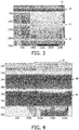
- FIG. 3 illustrates a screen shot of an M-mode ultrasound image of cardiac ablation in a sheep heart as generated by an ablation catheter of the type schematically illustrated in FIG. 1 .
- the vertical axis shows the distance from the transducer. The distance is given in pixels which can be converted into time or depth.
- the horizontal axis illustrates time, again given in pixels (increments of 20 pixels equals 1 second).
- the image shows the strong primary reflection 30 from the TPX/Pt ablation electrode, and in addition 2nd and 3rd order reflection peaks 31, 32.
- FIG. 4 illustrates a zoom made of the first TPX/Pt reflection peak 30, as indicated with reference numeral 33 on FIG. 3 .
- the two peaks (maxima indicated by reference numerals 40, 41) are observed.
- the positions of these reflections are related to the time-of-flight of the ultrasound signal, and therefore the acoustic path length through the transmission element.
- the maxima of the two peaks are observed to be relatively constant with respect to time in the first half of the image, however as can be seen during the period indicated with reference numeral 42 where the ablation process is running, the distance 43, 44 between the two peaks increases.
- the first peak 40 corresponds to the transition of the acoustic radiation into the transmission element
- the second peak 41 corresponds to the transition of the acoustic radiation out of the transmission element.
- the ultrasound radiation is propagating inside the transmission element. Due to the ablative process, the temperature of the ablation electrode and the tissue increases and as a result, the acoustical path length through the transparent ablation electrode increases too.
- the acoustic path length can be monitored. From analysis of the monitored data, it is possible to obtain sub-pixel resolution.
- the main physical effect which gives rise to the changes in the acoustical path length is the change of the speed of sound in dependence upon the temperature changes.
- FIG. 5 shows a graph of the peak separation 43, 44 as a function of time in the ablation period as indicated with reference numeral 42 in FIG. 4 .
- the vertical axis is peak separation in pixels and the horizontal axis is time in seconds.
- the graph shows measuring points 50 as well as a calculated line 51 of the expected thermal effect. The calculation was obtained by assuming 4 mm thick cardiac tissue, cold surfaces and a 6 mm diameter ablation catheter.
- the vertical axis includes only a single fitting parameter in the form of the product of the ablation power and thermal conductivity.
- the horizontal axis does not contain fitting parameters.
- FIG. 6 illustrates a graph correlating the peak separation (left vertical axis), the speed of sound (right vertical axis) and the temperature in degree Celsius (horizontal axis).
- the measurement points are shown as solid bullets 60 (a line is drawn through the points to guide the eye), moreover, a line 61 is shown indicating 0.25% expansion per °C of the acoustic path length for comparison to the data.
- the catheter is capable of accurately determining the temperature at the location of the point of contact between the ablation electrode and the tissue, which is the clinically interesting point.
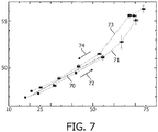
- FIG. 7 further illustrates peak separations as a function of temperature.
- FIG. 7 illustrates a laboratory experiment, where the acoustical path length between the two peaks was measured for a medical device with the distal end region submerged in a water bath for a series of constant temperatures.
- a line 70 is shown which indicate 0.25% expansion per °C of the acoustic path length for comparison to the data.
- Point connected by the line with reference numeral 71 connect data points obtained during temperature rise 72, whereas point connected by the line with reference numeral 73 connect data points obtained during temperature decent 74.
- thermal resolution is of the order of 1 °C within the range of clinical relevant temperatures.
- the temperature at the distal end may be determined based on a look-up table or a functional relationship between a parameter related to the acoustic path length and the temperature at the distal end, e.g. as deduced from a measurement as presented in FIG. 7 .
- Look-up table, functional relationships etc. may be stored by and computed in the controller unit or a computing unit in or connected to the controller unit.
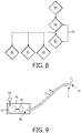
- FIG. 8 illustrates a flow diagram of some of the steps which may be performed in order to operate a medical device in accordance with embodiments of the present invention.
- the medical device may be positioned 80 in the region of interest, for example in close proximity of cardiac tissue to undergo ablation treatment.
- the transducers are operated to generate 81 acoustic radiation and to detect 82 the reflected acoustic radiation.
- the transducers may be operated continuously 83 during the investigation and treatment.
- the reflected acoustic radiation is detected in order to monitor 84 the region of interest during the procedure, and from the reflected acoustic radiation also the acoustic path length is deduced to determine the temperature 85 at the distal end.
- the treatment modality may be operated 86 in order to perform medical treatment.
- the tissue under treatment may undergo ablation.
- FIG. 9 schematically illustrates a medical device connected to a controller unit and in connection with a computer program product.
- the medical device comprises a catheter in accordance with embodiments of the present invention.
- the catheter comprises an elongated body 3 having a proximal end 90, a distal end 10, a distal end region 1 and a length axis 9 along the elongation.
- the catheter comprises one or more ultrasound transducers positioned in the distal end region and a transmission element 5 positioned at the extremity of the elongated body to couple acoustic radiation in and out of the catheter.
- the catheter is at the proximal end 90 connected to a controller unit 91, such as a dedicated purpose or general purpose computing unit for control of at least the ultrasound transducer(s) and for dealing with the signal treatment and extraction of detection results.
- a controller unit 91 such as a dedicated purpose or general purpose computing unit for control of at least the ultrasound transducer(s) and for dealing with the signal treatment and extraction of detection results.
- the detection of the acoustic path length through the transmission element and the determination of the temperature at the distal end are controlled by the controller unit 91.
- the controller unit may implement a computer system 92, such as a dedicated purpose or general purpose computing unit for controlling the device.
- the computer system may comprise storage means 93 for storing data which may be needed to operate the medical device or to store any acquired data, or for any other purpose where storage of data is desired.
- the computer system may be adapted to receive instructions from a computer program product 94 in order to operate the device.
- the computer program product may be comprised in a data carrier as illustrated in the Figure, however once loaded into the computer system it may be stored by, and run from, the storage means 93.
- a computer program may be stored/distributed on a suitable medium, such as an optical storage medium or a solid-state medium supplied together with or as part of other hardware, but may also be distributed in other forms, such as via the Internet or other wired or wireless telecommunication systems. Any reference signs in the claims should not be construed as limiting the scope.
Landscapes
- Health & Medical Sciences (AREA)
- Life Sciences & Earth Sciences (AREA)
- Physics & Mathematics (AREA)
- Engineering & Computer Science (AREA)
- Surgery (AREA)
- Medical Informatics (AREA)
- Veterinary Medicine (AREA)
- Nuclear Medicine, Radiotherapy & Molecular Imaging (AREA)
- Public Health (AREA)
- General Health & Medical Sciences (AREA)
- Biomedical Technology (AREA)
- Heart & Thoracic Surgery (AREA)
- Animal Behavior & Ethology (AREA)
- Molecular Biology (AREA)
- Biophysics (AREA)
- Radiology & Medical Imaging (AREA)
- Pathology (AREA)
- General Physics & Mathematics (AREA)
- Acoustics & Sound (AREA)
- Cardiology (AREA)
- Plasma & Fusion (AREA)
- Otolaryngology (AREA)
- Gynecology & Obstetrics (AREA)
- Ultra Sonic Daignosis Equipment (AREA)
- Surgical Instruments (AREA)
Claims (7)
- Ultraschallkatheter-Vorrichtung, umfassend:- einen länglichen Körper (3) mit einem proximalen Ende (90), einem distalen Ende (10), einem distalen Endbereich (1) und einer Längsachse (9) entlang der Ausdehnung;- einen oder mehrere Ultraschallwandler (4) zum Erzeugen von akustischer Strahlung, wobei der eine oder die mehreren Ultraschallwandler im distalen Endbereich innerhalb des länglichen Körpers positioniert sind;- ein Übertragungselement (5), das im Strahlungsweg der akustischen Strahlung positioniert ist, wobei das Übertragungselement im Wesentlichen für akustische Strahlung transparent ist und wobei das Übertragungselement eine integrierte Ablationselektrode umfasst;dadurch gekennzeichnet, dass sie weiter umfasst- eine Steuereinheit (91), die mit dem Ultraschallwandler wirkverbunden ist; wobei die Steuereinheit die akustische Weglänge durch das Übertragungselement erfasst und die Temperatur am distalen Ende aus der erfassten akustischen Weglänge bestimmt; und wobei der distale Endbereich weiter Fluidkanäle umfasst, welche die Abgabe von Fluid durch den länglichen Körper zu dem distalen Endbereich ermöglichen.
- Vorrichtung nach Anspruch 1, wobei das Übertragungselement einen polymerbasierten Körper umfasst, der mit einer Elektrode (20) bedeckt ist, die durch eine dünne leitende Schicht gebildet ist.
- Vorrichtung nach Anspruch 1, wobei das Übertragungselement eine Rückseite (21) aufweist, die im Allgemeinen dem Ultraschallwandler zugewandt ist, und eine der gegenüberliegenden Seite zugewandte Vorderseite (22), und wobei die Temperatur am distalen Ende basierend auf dem Erfassen einer Trennung von Reflexionsspitzen (40, 41) von einer Oberfläche der Rückseite des Übertragungselements und einer Oberfläche der Vorderseite des Übertragungselements bestimmt wird.
- Vorrichtung nach Anspruch 1, wobei der eine oder die mehreren Ultraschallwandler akustische Strahlung erzeugen können, die zur Überwachung eines Bereichs von Interesse und zum Erfassen der akustischen Weglänge durch das Übertragungselement geeignet ist.
- Vorrichtung nach Anspruch 1, wobei die Temperatur am distalen Ende basierend auf einer Nachschlagetabelle oder einer Abhängigkeitsbeziehung zwischen einem Parameter, der sich auf die akustische Weglänge bezieht, und der Temperatur am distalen Ende bestimmt wird.
- Vorrichtung nach Anspruch 1, wobei das Übertragungselement einen polymerbasierten Körper umfasst, der für akustische Strahlung im Wesentlichen transparent ist, wobei der polymerbasierte Körper eine Geschwindigkeitsänderung der akustischen Strahlung von mehr als 0,1 % pro Grad Celsius aufweist.
- Computerprogrammprodukt (94), das derart ausgelegt ist, dass ein Computersystem (92), das mindestens einen Computer mit Datenspeichermitteln (93) umfasst, eine medizinische Vorrichtung nach Anspruch 1 betreiben kann, um die Temperatur (85) am distalen Ende der medizinischen Vorrichtung aus der erfassten akustischen Weglänge durch das Übertragungselement zu bestimmen.
Applications Claiming Priority (3)
| Application Number | Priority Date | Filing Date | Title |
|---|---|---|---|
| EP09170526 | 2009-09-17 | ||
| PCT/IB2010/054153 WO2011033454A1 (en) | 2009-09-17 | 2010-09-15 | Medical ultrasound device with temperature detection at distal end |
| EP10760774A EP2477553A1 (de) | 2009-09-17 | 2010-09-15 | Medizinische ultraschallvorrichtung mit temperaturfühler am distalen ende |
Related Parent Applications (1)
| Application Number | Title | Priority Date | Filing Date |
|---|---|---|---|
| EP10760774A Division EP2477553A1 (de) | 2009-09-17 | 2010-09-15 | Medizinische ultraschallvorrichtung mit temperaturfühler am distalen ende |
Publications (2)
| Publication Number | Publication Date |
|---|---|
| EP3117776A1 EP3117776A1 (de) | 2017-01-18 |
| EP3117776B1 true EP3117776B1 (de) | 2019-01-23 |
Family
ID=43027702
Family Applications (2)
| Application Number | Title | Priority Date | Filing Date |
|---|---|---|---|
| EP16182768.8A Not-in-force EP3117776B1 (de) | 2009-09-17 | 2010-09-15 | Ultraschallkatheter mit temperaturerfassung am distalen ende |
| EP10760774A Withdrawn EP2477553A1 (de) | 2009-09-17 | 2010-09-15 | Medizinische ultraschallvorrichtung mit temperaturfühler am distalen ende |
Family Applications After (1)
| Application Number | Title | Priority Date | Filing Date |
|---|---|---|---|
| EP10760774A Withdrawn EP2477553A1 (de) | 2009-09-17 | 2010-09-15 | Medizinische ultraschallvorrichtung mit temperaturfühler am distalen ende |
Country Status (7)
| Country | Link |
|---|---|
| US (2) | US10743836B2 (de) |
| EP (2) | EP3117776B1 (de) |
| JP (1) | JP6270315B2 (de) |
| CN (1) | CN102497822B (de) |
| BR (1) | BR112012005696A8 (de) |
| RU (1) | RU2549528C2 (de) |
| WO (1) | WO2011033454A1 (de) |
Families Citing this family (10)
| Publication number | Priority date | Publication date | Assignee | Title |
|---|---|---|---|---|
| EP3117776B1 (de) | 2009-09-17 | 2019-01-23 | Koninklijke Philips N.V. | Ultraschallkatheter mit temperaturerfassung am distalen ende |
| JP5972581B2 (ja) * | 2012-01-23 | 2016-08-17 | 東芝メディカルシステムズ株式会社 | 超音波診断装置 |
| US10349824B2 (en) | 2013-04-08 | 2019-07-16 | Apama Medical, Inc. | Tissue mapping and visualization systems |
| CN110141177B (zh) * | 2013-04-08 | 2021-11-23 | 阿帕玛医疗公司 | 消融导管 |
| US10098694B2 (en) | 2013-04-08 | 2018-10-16 | Apama Medical, Inc. | Tissue ablation and monitoring thereof |
| WO2015000721A1 (en) * | 2013-07-03 | 2015-01-08 | Koninklijke Philips N.V. | Temperature distribution determining apparatus. |
| WO2015121096A1 (en) | 2014-02-12 | 2015-08-20 | Koninklijke Philips N.V. | Temperature distribution determination apparatus |
| JP2015204894A (ja) * | 2014-04-17 | 2015-11-19 | オリンパス株式会社 | 超音波治療装置 |
| CN113117266B (zh) * | 2019-12-30 | 2023-02-28 | 重庆融海超声医学工程研究中心有限公司 | 一种温度监测设备 |
| CN120194826B (zh) * | 2025-05-27 | 2025-07-22 | 中国空气动力研究与发展中心计算空气动力研究所 | 基于包络面积的复合材料内部温度的超声测量方法 |
Family Cites Families (23)
| Publication number | Priority date | Publication date | Assignee | Title |
|---|---|---|---|---|
| US5196006A (en) | 1989-04-25 | 1993-03-23 | Summit Technology, Inc. | Method and apparatus for excision endpoint control |
| US6690963B2 (en) | 1995-01-24 | 2004-02-10 | Biosense, Inc. | System for determining the location and orientation of an invasive medical instrument |
| US5941825A (en) * | 1996-10-21 | 1999-08-24 | Philipp Lang | Measurement of body fat using ultrasound methods and devices |
| JPH10127632A (ja) | 1996-11-06 | 1998-05-19 | Toshiba Corp | 超音波診断装置 |
| US6490474B1 (en) * | 1997-08-01 | 2002-12-03 | Cardiac Pathways Corporation | System and method for electrode localization using ultrasound |
| CN1058905C (zh) * | 1998-01-25 | 2000-11-29 | 重庆海扶(Hifu)技术有限公司 | 高强度聚焦超声肿瘤扫描治疗系统 |
| US20030130657A1 (en) * | 1999-08-05 | 2003-07-10 | Tom Curtis P. | Devices for applying energy to tissue |
| JP2003513691A (ja) | 1999-10-25 | 2003-04-15 | シーラス、コーポレイション | 血管を封止するための集束超音波の使用 |
| US7211044B2 (en) * | 2001-05-29 | 2007-05-01 | Ethicon Endo-Surgery, Inc. | Method for mapping temperature rise using pulse-echo ultrasound |
| US7001383B2 (en) | 2002-10-21 | 2006-02-21 | Biosense, Inc. | Real-time monitoring and mapping of ablation lesion formation in the heart |
| US7303530B2 (en) * | 2003-05-22 | 2007-12-04 | Siemens Medical Solutions Usa, Inc. | Transducer arrays with an integrated sensor and methods of use |
| US7156551B2 (en) * | 2003-06-23 | 2007-01-02 | Siemens Medical Solutions Usa, Inc. | Ultrasound transducer fault measurement method and system |
| JP4412925B2 (ja) | 2003-07-04 | 2010-02-10 | パナソニック株式会社 | 超音波診断装置 |
| US7275547B2 (en) | 2003-10-08 | 2007-10-02 | Boston Scientific Scimed, Inc. | Method and system for determining the location of a medical probe using a reference transducer array |
| US7527625B2 (en) | 2004-08-04 | 2009-05-05 | Olympus Corporation | Transparent electrode for the radiofrequency ablation of tissue |
| US7553284B2 (en) | 2005-02-02 | 2009-06-30 | Vaitekunas Jeffrey J | Focused ultrasound for pain reduction |
| US8702609B2 (en) * | 2007-07-27 | 2014-04-22 | Meridian Cardiovascular Systems, Inc. | Image-guided intravascular therapy catheters |
| CA2694734A1 (en) | 2007-07-27 | 2009-02-05 | R Tree Innovations, Llc | Inter-body implantation system and method |
| US10492854B2 (en) * | 2007-12-05 | 2019-12-03 | Biosense Webster, Inc. | Catheter-based acoustic radiation force impulse system |
| CN101283925A (zh) * | 2008-05-29 | 2008-10-15 | 迈德医疗科技(上海)有限公司 | 带有超声探头的射频消融电极 |
| CN101396299B (zh) | 2008-11-12 | 2010-11-10 | 郁如煌 | 与腹腔镜耦合的杜瓦连体式低温手术装置 |
| US20100168572A1 (en) * | 2008-12-30 | 2010-07-01 | Sliwa John W | Apparatus and Methods for Acoustic Monitoring of Ablation Procedures |
| EP3117776B1 (de) | 2009-09-17 | 2019-01-23 | Koninklijke Philips N.V. | Ultraschallkatheter mit temperaturerfassung am distalen ende |
-
2010
- 2010-09-15 EP EP16182768.8A patent/EP3117776B1/de not_active Not-in-force
- 2010-09-15 RU RU2012115115/14A patent/RU2549528C2/ru active
- 2010-09-15 BR BR112012005696A patent/BR112012005696A8/pt not_active IP Right Cessation
- 2010-09-15 WO PCT/IB2010/054153 patent/WO2011033454A1/en not_active Ceased
- 2010-09-15 JP JP2012529386A patent/JP6270315B2/ja not_active Expired - Fee Related
- 2010-09-15 US US13/393,857 patent/US10743836B2/en active Active
- 2010-09-15 EP EP10760774A patent/EP2477553A1/de not_active Withdrawn
- 2010-09-15 CN CN201080041298.0A patent/CN102497822B/zh not_active Expired - Fee Related
-
2020
- 2020-08-18 US US16/996,466 patent/US11497464B2/en active Active
Non-Patent Citations (1)
| Title |
|---|
| None * |
Also Published As
| Publication number | Publication date |
|---|---|
| US20200375569A1 (en) | 2020-12-03 |
| EP3117776A1 (de) | 2017-01-18 |
| CN102497822B (zh) | 2015-02-11 |
| US11497464B2 (en) | 2022-11-15 |
| JP2013505050A (ja) | 2013-02-14 |
| RU2012115115A (ru) | 2013-10-27 |
| BR112012005696A8 (pt) | 2017-10-10 |
| WO2011033454A1 (en) | 2011-03-24 |
| US20120165666A1 (en) | 2012-06-28 |
| CN102497822A (zh) | 2012-06-13 |
| JP6270315B2 (ja) | 2018-01-31 |
| RU2549528C2 (ru) | 2015-04-27 |
| US10743836B2 (en) | 2020-08-18 |
| EP2477553A1 (de) | 2012-07-25 |
| BR112012005696A2 (pt) | 2017-05-30 |
Similar Documents
| Publication | Publication Date | Title |
|---|---|---|
| US11497464B2 (en) | Medical ultrasound device with temperature detection at distal end | |
| EP2477572B1 (de) | Medizinische ultraschallvorrichtung mit krafterkennung | |
| EP2814397B1 (de) | System zur prüfung der auswirkungen einer ablationstherapie an herzgewebe mittels photoakustik | |
| JP5855739B2 (ja) | アブレーションカテーテルにおいて焼灼巣フィードバックのために角度方向付けを用いる単一トランスデューサ | |
| JP5976782B2 (ja) | 音響フィードバックを用いるrfアブレーションシステム用の装置及びインタフェース | |
| US9241687B2 (en) | Ablation probe with ultrasonic imaging capabilities | |
| AU2016259377A1 (en) | Using force sensor to give angle of ultrasound beam | |
| AU2005200102B2 (en) | Prediction and assessment of ablation of cardiac tissue | |
| JP2015536727A (ja) | 電気的及び機械的方法に基づく心臓活性化信号の再構成 | |
| WO2013123020A1 (en) | Ablation catheter with optic energy delivery system for photoacoustic tissue response | |
| CN219461380U (zh) | 一种消融导管 | |
| CN106963479B (zh) | 使用门控的超声和力测量的组织深度估计 | |
| CN116439820B (zh) | 一种消融导管 | |
| EP3226773B1 (de) | Systeme für verletzungsbildungsfeedback |
Legal Events
| Date | Code | Title | Description |
|---|---|---|---|
| PUAI | Public reference made under article 153(3) epc to a published international application that has entered the european phase |
Free format text: ORIGINAL CODE: 0009012 |
|
| STAA | Information on the status of an ep patent application or granted ep patent |
Free format text: STATUS: THE APPLICATION HAS BEEN PUBLISHED |
|
| AC | Divisional application: reference to earlier application |
Ref document number: 2477553 Country of ref document: EP Kind code of ref document: P |
|
| AK | Designated contracting states |
Kind code of ref document: A1 Designated state(s): AL AT BE BG CH CY CZ DE DK EE ES FI FR GB GR HR HU IE IS IT LI LT LU LV MC MK MT NL NO PL PT RO SE SI SK SM TR |
|
| STAA | Information on the status of an ep patent application or granted ep patent |
Free format text: STATUS: REQUEST FOR EXAMINATION WAS MADE |
|
| 17P | Request for examination filed |
Effective date: 20170718 |
|
| RBV | Designated contracting states (corrected) |
Designated state(s): AL AT BE BG CH CY CZ DE DK EE ES FI FR GB GR HR HU IE IS IT LI LT LU LV MC MK MT NL NO PL PT RO SE SI SK SM TR |
|
| GRAP | Despatch of communication of intention to grant a patent |
Free format text: ORIGINAL CODE: EPIDOSNIGR1 |
|
| STAA | Information on the status of an ep patent application or granted ep patent |
Free format text: STATUS: GRANT OF PATENT IS INTENDED |
|
| RIC1 | Information provided on ipc code assigned before grant |
Ipc: A61B 18/14 20060101ALI20180709BHEP Ipc: A61B 8/00 20060101ALI20180709BHEP Ipc: A61B 8/12 20060101AFI20180709BHEP Ipc: A61B 90/00 20160101ALN20180709BHEP |
|
| INTG | Intention to grant announced |
Effective date: 20180801 |
|
| RIN1 | Information on inventor provided before grant (corrected) |
Inventor name: SUIJVER, JAN FREDERIK Inventor name: MEGENS, MISCHA |
|
| GRAS | Grant fee paid |
Free format text: ORIGINAL CODE: EPIDOSNIGR3 |
|
| GRAA | (expected) grant |
Free format text: ORIGINAL CODE: 0009210 |
|
| STAA | Information on the status of an ep patent application or granted ep patent |
Free format text: STATUS: THE PATENT HAS BEEN GRANTED |
|
| AC | Divisional application: reference to earlier application |
Ref document number: 2477553 Country of ref document: EP Kind code of ref document: P |
|
| AK | Designated contracting states |
Kind code of ref document: B1 Designated state(s): AL AT BE BG CH CY CZ DE DK EE ES FI FR GB GR HR HU IE IS IT LI LT LU LV MC MK MT NL NO PL PT RO SE SI SK SM TR |
|
| REG | Reference to a national code |
Ref country code: GB Ref legal event code: FG4D |
|
| REG | Reference to a national code |
Ref country code: CH Ref legal event code: EP |
|
| REG | Reference to a national code |
Ref country code: AT Ref legal event code: REF Ref document number: 1090835 Country of ref document: AT Kind code of ref document: T Effective date: 20190215 |
|
| REG | Reference to a national code |
Ref country code: IE Ref legal event code: FG4D |
|
| REG | Reference to a national code |
Ref country code: DE Ref legal event code: R096 Ref document number: 602010056820 Country of ref document: DE |
|
| REG | Reference to a national code |
Ref country code: NL Ref legal event code: MP Effective date: 20190123 |
|
| PG25 | Lapsed in a contracting state [announced via postgrant information from national office to epo] |
Ref country code: NL Free format text: LAPSE BECAUSE OF FAILURE TO SUBMIT A TRANSLATION OF THE DESCRIPTION OR TO PAY THE FEE WITHIN THE PRESCRIBED TIME-LIMIT Effective date: 20190123 |
|
| PG25 | Lapsed in a contracting state [announced via postgrant information from national office to epo] |
Ref country code: NO Free format text: LAPSE BECAUSE OF FAILURE TO SUBMIT A TRANSLATION OF THE DESCRIPTION OR TO PAY THE FEE WITHIN THE PRESCRIBED TIME-LIMIT Effective date: 20190423 Ref country code: FI Free format text: LAPSE BECAUSE OF FAILURE TO SUBMIT A TRANSLATION OF THE DESCRIPTION OR TO PAY THE FEE WITHIN THE PRESCRIBED TIME-LIMIT Effective date: 20190123 Ref country code: SE Free format text: LAPSE BECAUSE OF FAILURE TO SUBMIT A TRANSLATION OF THE DESCRIPTION OR TO PAY THE FEE WITHIN THE PRESCRIBED TIME-LIMIT Effective date: 20190123 Ref country code: PT Free format text: LAPSE BECAUSE OF FAILURE TO SUBMIT A TRANSLATION OF THE DESCRIPTION OR TO PAY THE FEE WITHIN THE PRESCRIBED TIME-LIMIT Effective date: 20190523 Ref country code: ES Free format text: LAPSE BECAUSE OF FAILURE TO SUBMIT A TRANSLATION OF THE DESCRIPTION OR TO PAY THE FEE WITHIN THE PRESCRIBED TIME-LIMIT Effective date: 20190123 Ref country code: LT Free format text: LAPSE BECAUSE OF FAILURE TO SUBMIT A TRANSLATION OF THE DESCRIPTION OR TO PAY THE FEE WITHIN THE PRESCRIBED TIME-LIMIT Effective date: 20190123 Ref country code: PL Free format text: LAPSE BECAUSE OF FAILURE TO SUBMIT A TRANSLATION OF THE DESCRIPTION OR TO PAY THE FEE WITHIN THE PRESCRIBED TIME-LIMIT Effective date: 20190123 |
|
| REG | Reference to a national code |
Ref country code: AT Ref legal event code: MK05 Ref document number: 1090835 Country of ref document: AT Kind code of ref document: T Effective date: 20190123 |
|
| PG25 | Lapsed in a contracting state [announced via postgrant information from national office to epo] |
Ref country code: HR Free format text: LAPSE BECAUSE OF FAILURE TO SUBMIT A TRANSLATION OF THE DESCRIPTION OR TO PAY THE FEE WITHIN THE PRESCRIBED TIME-LIMIT Effective date: 20190123 Ref country code: LV Free format text: LAPSE BECAUSE OF FAILURE TO SUBMIT A TRANSLATION OF THE DESCRIPTION OR TO PAY THE FEE WITHIN THE PRESCRIBED TIME-LIMIT Effective date: 20190123 Ref country code: GR Free format text: LAPSE BECAUSE OF FAILURE TO SUBMIT A TRANSLATION OF THE DESCRIPTION OR TO PAY THE FEE WITHIN THE PRESCRIBED TIME-LIMIT Effective date: 20190424 Ref country code: IS Free format text: LAPSE BECAUSE OF FAILURE TO SUBMIT A TRANSLATION OF THE DESCRIPTION OR TO PAY THE FEE WITHIN THE PRESCRIBED TIME-LIMIT Effective date: 20190523 Ref country code: BG Free format text: LAPSE BECAUSE OF FAILURE TO SUBMIT A TRANSLATION OF THE DESCRIPTION OR TO PAY THE FEE WITHIN THE PRESCRIBED TIME-LIMIT Effective date: 20190423 |
|
| REG | Reference to a national code |
Ref country code: DE Ref legal event code: R097 Ref document number: 602010056820 Country of ref document: DE |
|
| PG25 | Lapsed in a contracting state [announced via postgrant information from national office to epo] |
Ref country code: EE Free format text: LAPSE BECAUSE OF FAILURE TO SUBMIT A TRANSLATION OF THE DESCRIPTION OR TO PAY THE FEE WITHIN THE PRESCRIBED TIME-LIMIT Effective date: 20190123 Ref country code: DK Free format text: LAPSE BECAUSE OF FAILURE TO SUBMIT A TRANSLATION OF THE DESCRIPTION OR TO PAY THE FEE WITHIN THE PRESCRIBED TIME-LIMIT Effective date: 20190123 Ref country code: CZ Free format text: LAPSE BECAUSE OF FAILURE TO SUBMIT A TRANSLATION OF THE DESCRIPTION OR TO PAY THE FEE WITHIN THE PRESCRIBED TIME-LIMIT Effective date: 20190123 Ref country code: RO Free format text: LAPSE BECAUSE OF FAILURE TO SUBMIT A TRANSLATION OF THE DESCRIPTION OR TO PAY THE FEE WITHIN THE PRESCRIBED TIME-LIMIT Effective date: 20190123 Ref country code: IT Free format text: LAPSE BECAUSE OF FAILURE TO SUBMIT A TRANSLATION OF THE DESCRIPTION OR TO PAY THE FEE WITHIN THE PRESCRIBED TIME-LIMIT Effective date: 20190123 Ref country code: AL Free format text: LAPSE BECAUSE OF FAILURE TO SUBMIT A TRANSLATION OF THE DESCRIPTION OR TO PAY THE FEE WITHIN THE PRESCRIBED TIME-LIMIT Effective date: 20190123 Ref country code: SK Free format text: LAPSE BECAUSE OF FAILURE TO SUBMIT A TRANSLATION OF THE DESCRIPTION OR TO PAY THE FEE WITHIN THE PRESCRIBED TIME-LIMIT Effective date: 20190123 |
|
| PG25 | Lapsed in a contracting state [announced via postgrant information from national office to epo] |
Ref country code: SM Free format text: LAPSE BECAUSE OF FAILURE TO SUBMIT A TRANSLATION OF THE DESCRIPTION OR TO PAY THE FEE WITHIN THE PRESCRIBED TIME-LIMIT Effective date: 20190123 |
|
| PLBE | No opposition filed within time limit |
Free format text: ORIGINAL CODE: 0009261 |
|
| STAA | Information on the status of an ep patent application or granted ep patent |
Free format text: STATUS: NO OPPOSITION FILED WITHIN TIME LIMIT |
|
| PG25 | Lapsed in a contracting state [announced via postgrant information from national office to epo] |
Ref country code: AT Free format text: LAPSE BECAUSE OF FAILURE TO SUBMIT A TRANSLATION OF THE DESCRIPTION OR TO PAY THE FEE WITHIN THE PRESCRIBED TIME-LIMIT Effective date: 20190123 |
|
| 26N | No opposition filed |
Effective date: 20191024 |
|
| PG25 | Lapsed in a contracting state [announced via postgrant information from national office to epo] |
Ref country code: SI Free format text: LAPSE BECAUSE OF FAILURE TO SUBMIT A TRANSLATION OF THE DESCRIPTION OR TO PAY THE FEE WITHIN THE PRESCRIBED TIME-LIMIT Effective date: 20190123 |
|
| PG25 | Lapsed in a contracting state [announced via postgrant information from national office to epo] |
Ref country code: TR Free format text: LAPSE BECAUSE OF FAILURE TO SUBMIT A TRANSLATION OF THE DESCRIPTION OR TO PAY THE FEE WITHIN THE PRESCRIBED TIME-LIMIT Effective date: 20190123 |
|
| PG25 | Lapsed in a contracting state [announced via postgrant information from national office to epo] |
Ref country code: MC Free format text: LAPSE BECAUSE OF FAILURE TO SUBMIT A TRANSLATION OF THE DESCRIPTION OR TO PAY THE FEE WITHIN THE PRESCRIBED TIME-LIMIT Effective date: 20190123 |
|
| REG | Reference to a national code |
Ref country code: CH Ref legal event code: PL |
|
| PG25 | Lapsed in a contracting state [announced via postgrant information from national office to epo] |
Ref country code: CH Free format text: LAPSE BECAUSE OF NON-PAYMENT OF DUE FEES Effective date: 20190930 Ref country code: LI Free format text: LAPSE BECAUSE OF NON-PAYMENT OF DUE FEES Effective date: 20190930 Ref country code: IE Free format text: LAPSE BECAUSE OF NON-PAYMENT OF DUE FEES Effective date: 20190915 Ref country code: LU Free format text: LAPSE BECAUSE OF NON-PAYMENT OF DUE FEES Effective date: 20190915 |
|
| REG | Reference to a national code |
Ref country code: BE Ref legal event code: MM Effective date: 20190930 |
|
| PG25 | Lapsed in a contracting state [announced via postgrant information from national office to epo] |
Ref country code: BE Free format text: LAPSE BECAUSE OF NON-PAYMENT OF DUE FEES Effective date: 20190930 |
|
| PG25 | Lapsed in a contracting state [announced via postgrant information from national office to epo] |
Ref country code: CY Free format text: LAPSE BECAUSE OF FAILURE TO SUBMIT A TRANSLATION OF THE DESCRIPTION OR TO PAY THE FEE WITHIN THE PRESCRIBED TIME-LIMIT Effective date: 20190123 |
|
| PG25 | Lapsed in a contracting state [announced via postgrant information from national office to epo] |
Ref country code: HU Free format text: LAPSE BECAUSE OF FAILURE TO SUBMIT A TRANSLATION OF THE DESCRIPTION OR TO PAY THE FEE WITHIN THE PRESCRIBED TIME-LIMIT; INVALID AB INITIO Effective date: 20100915 Ref country code: MT Free format text: LAPSE BECAUSE OF FAILURE TO SUBMIT A TRANSLATION OF THE DESCRIPTION OR TO PAY THE FEE WITHIN THE PRESCRIBED TIME-LIMIT Effective date: 20190123 |
|
| PG25 | Lapsed in a contracting state [announced via postgrant information from national office to epo] |
Ref country code: MK Free format text: LAPSE BECAUSE OF FAILURE TO SUBMIT A TRANSLATION OF THE DESCRIPTION OR TO PAY THE FEE WITHIN THE PRESCRIBED TIME-LIMIT Effective date: 20190123 |
|
| REG | Reference to a national code |
Ref country code: FR Ref legal event code: PLFP Year of fee payment: 13 |
|
| PGFP | Annual fee paid to national office [announced via postgrant information from national office to epo] |
Ref country code: GB Payment date: 20230926 Year of fee payment: 14 |
|
| PGFP | Annual fee paid to national office [announced via postgrant information from national office to epo] |
Ref country code: FR Payment date: 20230926 Year of fee payment: 14 Ref country code: DE Payment date: 20230928 Year of fee payment: 14 |
|
| REG | Reference to a national code |
Ref country code: DE Ref legal event code: R119 Ref document number: 602010056820 Country of ref document: DE |
|
| GBPC | Gb: european patent ceased through non-payment of renewal fee |
Effective date: 20240915 |
|
| PG25 | Lapsed in a contracting state [announced via postgrant information from national office to epo] |
Ref country code: DE Free format text: LAPSE BECAUSE OF NON-PAYMENT OF DUE FEES Effective date: 20250401 |
|
| PG25 | Lapsed in a contracting state [announced via postgrant information from national office to epo] |
Ref country code: GB Free format text: LAPSE BECAUSE OF NON-PAYMENT OF DUE FEES Effective date: 20240915 |
|
| PG25 | Lapsed in a contracting state [announced via postgrant information from national office to epo] |
Ref country code: FR Free format text: LAPSE BECAUSE OF NON-PAYMENT OF DUE FEES Effective date: 20240930 |