EP3118076B1 - Systèmes et procédés de freinage électromécanique à commande de demande de puissance - Google Patents
Systèmes et procédés de freinage électromécanique à commande de demande de puissance Download PDFInfo
- Publication number
- EP3118076B1 EP3118076B1 EP16177720.6A EP16177720A EP3118076B1 EP 3118076 B1 EP3118076 B1 EP 3118076B1 EP 16177720 A EP16177720 A EP 16177720A EP 3118076 B1 EP3118076 B1 EP 3118076B1
- Authority
- EP
- European Patent Office
- Prior art keywords
- velocity
- current
- command
- force
- setpoint
- Prior art date
- Legal status (The legal status is an assumption and is not a legal conclusion. Google has not performed a legal analysis and makes no representation as to the accuracy of the status listed.)
- Active
Links
Images



Classifications
-
- B—PERFORMING OPERATIONS; TRANSPORTING
- B60—VEHICLES IN GENERAL
- B60T—VEHICLE BRAKE CONTROL SYSTEMS OR PARTS THEREOF; BRAKE CONTROL SYSTEMS OR PARTS THEREOF, IN GENERAL; ARRANGEMENT OF BRAKING ELEMENTS ON VEHICLES IN GENERAL; PORTABLE DEVICES FOR PREVENTING UNWANTED MOVEMENT OF VEHICLES; VEHICLE MODIFICATIONS TO FACILITATE COOLING OF BRAKES
- B60T8/00—Arrangements for adjusting wheel-braking force to meet varying vehicular or ground-surface conditions, e.g. limiting or varying distribution of braking force
- B60T8/17—Using electrical or electronic regulation means to control braking
-
- B—PERFORMING OPERATIONS; TRANSPORTING
- B60—VEHICLES IN GENERAL
- B60T—VEHICLE BRAKE CONTROL SYSTEMS OR PARTS THEREOF; BRAKE CONTROL SYSTEMS OR PARTS THEREOF, IN GENERAL; ARRANGEMENT OF BRAKING ELEMENTS ON VEHICLES IN GENERAL; PORTABLE DEVICES FOR PREVENTING UNWANTED MOVEMENT OF VEHICLES; VEHICLE MODIFICATIONS TO FACILITATE COOLING OF BRAKES
- B60T13/00—Transmitting braking action from initiating means to ultimate brake actuator with power assistance or drive; Brake systems incorporating such transmitting means, e.g. air-pressure brake systems
- B60T13/74—Transmitting braking action from initiating means to ultimate brake actuator with power assistance or drive; Brake systems incorporating such transmitting means, e.g. air-pressure brake systems with electrical assistance or drive
- B60T13/741—Transmitting braking action from initiating means to ultimate brake actuator with power assistance or drive; Brake systems incorporating such transmitting means, e.g. air-pressure brake systems with electrical assistance or drive acting on an ultimate actuator
-
- B—PERFORMING OPERATIONS; TRANSPORTING
- B60—VEHICLES IN GENERAL
- B60T—VEHICLE BRAKE CONTROL SYSTEMS OR PARTS THEREOF; BRAKE CONTROL SYSTEMS OR PARTS THEREOF, IN GENERAL; ARRANGEMENT OF BRAKING ELEMENTS ON VEHICLES IN GENERAL; PORTABLE DEVICES FOR PREVENTING UNWANTED MOVEMENT OF VEHICLES; VEHICLE MODIFICATIONS TO FACILITATE COOLING OF BRAKES
- B60T13/00—Transmitting braking action from initiating means to ultimate brake actuator with power assistance or drive; Brake systems incorporating such transmitting means, e.g. air-pressure brake systems
- B60T13/74—Transmitting braking action from initiating means to ultimate brake actuator with power assistance or drive; Brake systems incorporating such transmitting means, e.g. air-pressure brake systems with electrical assistance or drive
- B60T13/746—Transmitting braking action from initiating means to ultimate brake actuator with power assistance or drive; Brake systems incorporating such transmitting means, e.g. air-pressure brake systems with electrical assistance or drive and mechanical transmission of the braking action
-
- B—PERFORMING OPERATIONS; TRANSPORTING
- B64—AIRCRAFT; AVIATION; COSMONAUTICS
- B64C—AEROPLANES; HELICOPTERS
- B64C25/00—Alighting gear
- B64C25/32—Alighting gear characterised by elements which contact the ground or similar surface
- B64C25/42—Arrangement or adaptation of brakes
- B64C25/44—Actuating mechanisms
Definitions
- the present disclosure relates generally to electromechanical actuator systems and, more specifically, to electromechanical braking systems and methods with power demand control.
- Electromechanical brake systems are known in the art, as are other electromechanical actuator systems. These systems draw electric power from a power supply for operation. During peak power draw, the amount of power demanded can be substantial. To meet the peak power demand of electromechanical actuator systems, an appropriately sized power supply and associated conductors should be available. As the peak power demand increases, the size and weight of the power supply and associated components usually increase as well. In environments such as aircrafts, however, there is an ever present desire to reduce the size and weight of on-board items. In addition, on aircraft, the power available is limited.
- a controller for an electromechanical brake actuator is provided according to various embodiments.
- the EBA has a motor that is driven in response to a motor drive signal generated by the controller.
- the controller includes a velocity limiter and a current limiter.
- the velocity limiter limits a velocity command to a limited velocity command in response to a measured braking force signal output.
- the limited velocity command has a positive velocity limit boundary defined between a positive maximum velocity limit setpoint and a positive minimum velocity limit setpoint and a lower velocity limit boundary defined between a negative maximum velocity limit setpoint and a negative minimum velocity limit setpoint.
- the current limiter limits a current command to a limited current command in response to the measured braking force signal output.
- the limited current command has a positive current limit boundary defined between a positive maximum current limit setpoint and a positive minimum current limit setpoint and a lower current boundary defined between a negative maximum current limit setpoint and a negative minimum current limit setpoint.
- a method for limiting peak power demand of a controller for an electromechanical brake actuator having a motor is provided according to various embodiments.
- the electromechanical brake actuator is operative to apply a braking force to brake a wheel of a vehicle.
- the method comprises limiting, by the controller, a velocity command to a limited velocity command and a current command to a limited current command in response to a measured braking force signal output.
- the limited velocity command has a positive boundary defined between a positive maximum velocity limit setpoint and a positive minimum velocity limit setpoint and a negative boundary defined between a negative maximum velocity limit setpoint and a negative minimum velocity setpoint.
- the limited current command has a positive current limit boundary defined between a positive maximum current limit setpoint and a positive minimum current limit setpoint and a negative current boundary defined between a negative maximum current limit setpoint and a negative current limit setpoint.
- the controller outputs a motor drive signal to the motor in accordance with the limited current command.
- a system for limiting peak power demand of a controller for an electromechanical brake actuator having a motor is provided according to various embodiments.
- the motor is driven in response to a motor drive signal generated by a controller.
- the electromechanical brake actuator is operative to apply a braking force to brake a wheel of a vehicle.
- the system comprises a force sensor of the electromechanical brake actuator and configured to detect a measured braking force. An output of the force sensor is fed back to the controller as a force feedback signal.
- a position/velocity sensor of the electromechanical brake actuator and configured to detect a measured velocity. An output of the position/velocity sensor comprises a measured velocity signal output.
- a current sensor of the electromechanical brake actuator and configured to detect a measured current. An output of the current sensor comprises a measured current signal output.
- the controller is configured to reduce peak power demand based on the force feedback signal from the force sensor.
- the controller comprises a velocity limiter for limiting a velocity command to a limited velocity command in response to the measured braking force.
- the limited velocity command has a positive velocity limit boundary defined between a positive maximum velocity limit setpoint and a positive minimum velocity limit setpoint and a negative velocity limit boundary defined between a negative maximum velocity limit setpoint and a negative minimum velocity limit setpoint.
- the current limiter limits a current command to a limited current command in response to the measured braking force.
- the limited current command has a positive current limit boundary defined between a positive maximum current limit setpoint and a positive minimum current limit setpoint and a negative current boundary defined between a negative maximum current limit setpoint and a negative minimum current limit setpoint.
- Various embodiments are directed to electromechanical braking systems with power demand control for a vehicle and methods for limiting peak power demand of a controller for an electromechanical brake actuator.
- various embodiments reduce the amount of power needed for control of the electromechanical brake actuator.
- the electromechanical brake actuator is operative to apply a braking force to brake a wheel of a vehicle.
- the amount of power is reduced by limiting a motor velocity and a motor current based on a measured (braking) force output signal.
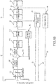
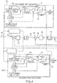
- FIGS. 1A and 1B a functional block diagram of the controller and actuator is shown.
- FIGS. 1A and 1B (inclusive of FIG. 2 ) also represent a control system and method.
- the control method uses braking force to limit peak power demand on the power supply.
- the control functions of the controller may be embodied as executable logic that is executed by a processor of the controller.
- Dedicated circuitry may be used to carry out the control functions described herein.
- the controller 26 uses a nested loop feedback arrangement as illustrated to generate a motor drive signal from an input braking command (i.e., a force command 100).
- the nested loop feedback arrangement generally comprises a current control loop, a velocity control loop, a position control loop, and a force control loop.
- the current control receives a current command from the velocity control.
- the motor current is directly proportional to torque (and, thus, braking force).
- the velocity control loop encloses the current loop of the control system. Velocity commands are received from the position control loop and the force control loop.
- the velocity control loop controls the speed at which the actuator moves toward the brake to satisfy slew rate control and reduction of peak power draw requirements.
- the position control loop encloses the velocity loop of the control system and enables control of the electromechanical actuator position.
- the force control loop provides independent force control for each electromechanical actuator in the electromechanical braking system.
- an electromechanical brake actuator 28 generally includes a motor 30 and gear train 32 that drives an actuator ram (also referred to as a force applicator) 35 in an axial direction toward and away from a brake stack 36 (referred to simply in FIGS. 1A and 1B as "brake") .
- the motor 30 drives the gear train 32, which in turn drives a ballscrew assembly 34.
- the ballscrew assembly 34 drives the actuator ram 35 back and forth in an axial direction so as to exert a braking force on the brake stack 36.
- the motor and gear train 32 is controlled by a controller 26 causing the actuator ram to extend toward the brake stack.
- the controller 26 controls the motor and gear train 32 to drive the actuator ram 35 in the reverse direction away from the brake stack 36 (i.e., to retract). In the event no braking command is present, it is desirable to provide a running clearance (also referred to herein as "free space") between the brake engagement surface of the actuator ram 35 and the brake stack 36. Accordingly, the controller 26 controls the motor 30 and gear train 32 to provide the desired running clearance when braking is not commanded.
- a control system may include multiple, identically operated actuators 28 each on a wheel for exerting braking force on the brake stack 36.
- Each actuator 28 may have its own force sensor 44, position/velocity sensor 46, and current sensor 48 as hereinafter described that provide feedback signals to the appropriate controller(s) 26.
- the controller 26 receives an input in the form of an input signal, such as a force or braking command signal.
- the value of the force command signal is typically proportionally based on the degree to which the pilot has depressed a corresponding brake pedal.
- the force command signal may be based on the results of an antiskid control algorithm carried out by the controller 26 or elsewhere within an aircraft.
- the force command signal may have a low value that causes the controller 26 to drive the motor 30 and gear train 32 such that the actuator ram exerts a light braking force (i.e., a low braking force such as when the pilot has lightly depressed the corresponding brake pedal on the brake).
- the force command signal may have a high value that causes the controller 26 to drive the motor 30 and gear train 32 such that the actuator ram exerts a heavy braking force on the brake stack 36.
- the actuator 28 includes a force sensor 44 that detects the braking force exerted by the actuator ram onto the brake stack 36. The output of the force sensor 44 is fed back as a force feedback signal 50 and is input to the controller 26 (more specifically a first adder 102 thereof) for performing force based control functions over the actuator 28.
- the force sensor 44 may be any type of known force sensor including, but not limited to, a force load cell or the like.
- the speed of rotation of the actuator motor (i.e., the velocity) is limited based on a measured force as reflected in the force feedback signal 50.
- the force feedback signal may also be referred to herein as a measured braking force output signal 50.
- the actuator 28 further includes a position/velocity sensor 46.
- the position/velocity sensor 46 is embodied as a resolver that senses the position of the rotor of the motor in the motor and gear train 32. Based on the output of the resolver, the controller 26 is able to detect the direction, number of revolutions of the rotor per unit time and the angular velocity of the rotor (e.g., in revolutions per minute) per unit time. As the ratio of the gear train of the motor 30 and gear train 32 in combination with the actuator ram is known, the controller 26 is able to compute the relative position of the actuator ram and motor velocity based on the output of the resolver.
- the output of the resolver provides relative feedback data that can be converted to a position value of the ram 34 and/or an angular velocity value of the motor. That is, in embodiments where the position/velocity sensor 46 is a resolver, rotor position and rotor velocity can be interchanged by tracking resolver output with a position counter and timer (e.g., position accumulator) and making a comparison against a reference location for the actuator ram. Therefore, speed (i.e., angular velocity) may be determined from position and/or there may be a separate speed (velocity) sensor.
- the position/velocity sensor 46 can be embodied as separate sensors, one for providing absolute or relative position feedback 47 to the controller 26 and the other for providing motor velocity feedback 52 to the controller 26.
- position feedback information assists the controller 26 in performing position based control functions of the actuator 28 and velocity feedback information assists the controller 26 in performing velocity based control functions of the actuator 28.
- the motor 30 may be a brushless DC motor. Consequently, the controller 26 also utilizes the output of the resolver to determine the appropriate phasing of the power signals provided to the motor 30 via a motor drive signal (as hereinafter described) to provide a desired motor commutation. In this manner, there is no need for separate position sensors for the DC motor and the actuator ram, respectively.
- the controller 26 receives an input in the form of an input signal, such as a force or braking command signal 100.
- the first adder 102 compares the force command 100 and the measured force signal output 50 from the force sensor 44.
- the difference signal (i.e., the force error) from the first adder 102 is input to a force/position control block 104 that acts on the difference signal to generate a velocity command 106.
- the velocity command is input to a velocity limiter 108 ( FIGS. 1A and 2 ) that limits the commanded velocity to a value ranging from a positive maximum velocity limit setpoint (W2) to a negative maximum velocity limit setpoint (W4).
- the output of the velocity limiter is a limited velocity command 120.
- An algorithm as known to one skilled in the art indicates that in order to achieve the specific measured force signal output 50 in a certain time duration, the motor should spin at a certain speed (i.e., a certain angular velocity).
- the velocity command 106 commands the motor to spin at the certain speed.
- the limited velocity command 120 addresses the maximum and minimum limits that the motor can spin.
- the portion of the block diagram of FIG. 1A includes the velocity limiter 108 used to generate positive and negative maximum and minimum velocity limits for the motor.
- the velocity limiter 108 includes a positive velocity limit generation branch 108a and a negative velocity limit generation branch 108b as depicted more specifically in FIG. 2 .
- the actuator ram may advance the actuator ram into the brake stack.
- the actuator moves the actuator ram away from the brake stack.
- the actuator when the motor spins in the positive, clockwise direction, the actuator moves the actuator ram away from the brake stack. When the motor spins in a negative, counterclockwise direction, the actuator ram may advance the actuator ram into the brake stack.
- the velocity command is based on a measured braking force signal output (50 in FIGS. 1A , 1B , and 2 ).
- the positive velocity limit generation branch 108a may receive a positive maximum velocity limit setpoint (W2) and a positive minimum velocity limit setpoint (W1).
- the negative velocity limit generation branch 108b receives a negative maximum velocity limit setpoint (W3) and a negative minimum velocity setpoint (W4).
- W1 and W2 define a positive velocity limit boundary between the positive maximum and minimum velocity limit setpoints.
- W3 and W4 define a negative velocity limit boundary between the negative maximum and minimum velocity limit setpoints. Different velocity limit setpoint values may be tried in order to bring the peak power demand below the requirements limit.
- W1 and W2 define respectively the maximum and minimum speed commands at which the motor can spin in the positive, clockwise direction
- W3 and W4 define respectively the maximum and minimum speed commands at which the motor can spin in the negative, counterclockwise direction.
- the product 150 is output to a velocity saturation adder 107 that adds the product 150 and the negative maximum velocity limit setpoint (W4).
- the output (the sum of product 150 and the positive maximum velocity limit setpoint) of velocity saturation adder 107 is bounded between the positive maximum velocity limit setpoint and the positive minimum velocity limit setpoint for the positive boundary velocity and between the negative maximum velocity limit and the negative minimum velocity limit for the negative boundary velocity using a velocity limit block 109.
- the output of the velocity limiter is a limited velocity command 120.
- FIG. 3 is a graph plotting the operating range of the electric motor of one of the actuators in the velocity/force plane, the operating range including a boundary defining a first straight line A, corresponding to a stage during which the ram is approaching the disks at maximum positive velocity.
- the velocity command limit output changes according to the line B until the braking force reaches F2, when the velocity command is defined by the line C. There is no braking force until the ram is against the brake.
- FIG. 3 illustrates that as braking force increases above F1, a lower velocity command is output from F1 to F2, after which the velocity command limit does not change anymore.
- a second adder 122 compares the limited velocity command 120 and the measured velocity signal output 52 from the position/velocity sensor 46 (FIG. IB).
- a difference signal (i.e., a "velocity error") 124 from the second adder 122 is sent to a velocity control compensator block 126 that acts on the difference signal from the second adder 122 to generate a motor current command 128.
- the current command 128 is input to a current limiter 130.
- the output of the current limiter 130 is a limited current command 132.
- the current limiter 130 is used to generate positive and negative maximum and minimum current limits for the motor.
- the current limiter 130 includes a positive current limit generation branch 130a and a negative current limit generation branch 130b as depicted more specifically in FIG. 4 .
- the positive and negative current limit calculation is based on the measured braking force.
- the positive current limit generation branch 130a may receive a positive maximum current limit setpoint (12) and a positive minimum current limit setpoint (I1).
- the negative current limit generation branch 130b may receive a negative maximum current limit setpoint (13) and a negative minimum current setpoint (14).
- 11 and 12 define a positive current limit boundary between the positive maximum and minimum current limits.
- 13 and 14 define a negative current limit boundary between the negative maximum and minimum current limits.
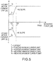
- the measured braking force (more particularly, the force feedback signal) is compared to the force setpoint F3 ( FIGS. 4 and 5 ).
- the difference from adder 135 is subjected to a multiplication factor (+ slope for 130a and -slope for 130b ( FIGS. 4 and 5 )).
- Slope is calculated using the tunable setpoints on the x-axis (F3 and F4) and the y-axis (I1, I2, I3, and I4) shown in FIG. 5 to reduce the peak power demand.
- the product 152 is output to a current saturation adder 131 that adds the product 152 with the positive minimum current limit setpoint (11).
- the product 152 is output to a current saturation adder 131 that adds the product 152 with the negative minimum current limit setpoint (I3).
- the output of current saturation adder 131 is bounded between the positive maximum current and the positive minimum current limit for the positive boundary current and between the negative maximum current and the negative minimum current for the negative boundary current using a current limit block 137.
- the output of the current limiter 130 is the limited current command 132.
- the current limiter 130 uses the measured braking force and limits the current command to a value I1 if the measured braking force is less than F3 and increases in value as the measured braking force increases from F3 to F4 ( FIG. 5 ).
- F3 has a low value relative to F4.
- the current command is limited to a value less than or equal to 11 when the actuator ram is not touching the brake (i.e., when the actuator ram is in free space), or when the measured force is below a specified threshold value F3.
- the current command may be a negative value representing the commanding of a retraction of the actuator ram, a positive value representing the commanding of an advancement of or force application with the actuator ram, and zero representing no movement of the actuator ram.
- the negative value may represent the commanding of the advancement of or force application with the actuator ram and the positive value representing the commanding of the retraction of the actuator ram.
- the motor current is directly proportional to torque (i.e., braking force).
- the current and velocity limits are varied to meet the recommended peak power demand.
- the velocity and current control loops use variable slew rates based on the measured force.
- FIG. 5 illustrates that as the braking force increases, a higher current command is output in order for the motor to be able to apply the required braking force or torque.
- a third adder 134 compares the limited current command 132 and the measured current signal output 136 from the current sensor 48.
- the difference signal i.e., the "current error" 138
- the difference signal is input to a current control compensator block 140 that acts on the difference signal 138 from the third adder 134 to generate a voltage signal that is fed to the motor drive 142 to spin the motor 30.
- the voltage signal comprises the motor drive signal.
- the motor 30 drives the gear train 32, which in turn drives the ballscrew assembly 34.
- the ballscrew assembly 34 drives the actuator ram 35 back and forth in an axial direction so as to exert a braking force on the brake stack 36.
- Reaction of the ballscrew assembly which corresponds to load reaction force of the actuator ram, is sensed through the force sensor.
- the output of the force sensor is indicative of the braking force applied by the actuator ram to the brake.
- the slew rate is changed based on the braking force.
- the actuator ram is off the brake (i.e., the force command may be substantially zero (i.e., within 5% of zero))
- the current limiter limits the current as previously described.
- there is a no load slew rate as there is no load being applied.
- Operational electrical power for motor drive signal generation by the motor drive 142 can be derived from a power supply.
- the power supply can be any suitable power source available from the aircraft.
- the power supply can be DC or AC power busses (connected to the controller directly or via a voltage converter), a battery, an independent power generator or combination of sources where one source supplements for another if the first were to fail to supply power.
- the controller 26 uses a closed loop feedback arrangement to generate the motor drive signal in accordance with the input braking command (i.e., the force command).
- the controller 26 can use velocity compensation and current compensation to convert the input braking command (i.e., the force command) into a limited current command.
- the controller 26 can use velocity compensation and current compensation to convert the input braking command (i.e., the force command) into a limited current command.
- the controller 26 can use velocity compensation and current compensation to convert the input braking command (i.e., the force command) into a limited current command.
- the controller 26 can use velocity compensation and current compensation to convert the input braking command (i.e., the force command) into a limited current command.
- the controller 26 can use velocity compensation and current compensation to convert the input braking command (i.e., the force command) into a limited current command.
- the controller 26 can use velocity compensation and current compensation to convert the input braking command (i.e., the force command) into a limited current command.
- the power supply may be smaller and lighter than a power supply sized to meet the peak power demands without current limits. More power is available for aircraft functions other than meeting the peak power demands of the electromechanical actuator systems such as electromechanical brake systems. It is important to ensure that the actuators cannot draw power greater than the maximum authorized power.
- references to "one embodiment,” “an embodiment,” “an example embodiment,” etc. indicate that the embodiment described may include a particular feature, structure, or characteristic, but every embodiment may not necessarily include the particular feature, structure, or characteristic. Moreover, such phrases are not necessarily referring to the same embodiment. Further, when a particular feature, structure, or characteristic is described in connection with an embodiment, it is submitted that it is within the knowledge of one skilled in the art to affect such feature, structure, or characteristic in connection with other embodiments whether or not explicitly described. After reading the description, it will be apparent to one skilled in the relevant art(s) how to implement the disclosure in alternative embodiments.
Landscapes
- Engineering & Computer Science (AREA)
- Mechanical Engineering (AREA)
- Transportation (AREA)
- Aviation & Aerospace Engineering (AREA)
- Braking Systems And Boosters (AREA)
- Control Of Electric Motors In General (AREA)
Claims (15)
- Dispositif de commande (26) pour un actionneur de frein électromécanique (28) ayant un moteur (30) qui est entraîné en réponse à un signal d'entraînement de moteur généré par le dispositif de commande (26) comprenant :un limiteur de vitesse (108) pour limiter une commande de vitesse à une commande de vitesse limitée (120) en réponse à une sortie de signal de force de freinage mesurée (50), la commande de vitesse limitée (120) ayant une limite limite de vitesse positive définie entre une valeur de consigne limite de vitesse maximum positive (W2) et une valeur de consigne limite de vitesse minimum positive (W1) et une limite limite de vitesse négative définie entre une valeur de consigne limite de vitesse maximum négative (W3) et une valeur de consigne limite de vitesse minimum négative (W4) ; etun limiteur de courant (130) pour limiter une commande de courant à une commande de courant limitée (132) en réponse à la sortie de signal de force de freinage mesurée (50), la commande de courant limitée (132) ayant une limite limite de courant positive définie entre une valeur de consigne limite de courant maximum positive (I2) et une valeur de consigne limite de courant minimum positive (I1) et une limite de courant négative définie entre une valeur de consigne limite de courant maximum négative (I3) et une valeur de consigne limite de courant minimum négative (I4).
- Dispositif de commande (26) selon la revendication 1, dans lequel la commande de vitesse limitée (120) et la commande de courant limitée (132) sont basées sur la sortie de signal de force de freinage mesurée (50) telle que détectée par un capteur de force (44) et une sortie du capteur de force (44) est renvoyée au dispositif de commande (26) en tant que signal de rétroaction de force (50).
- Dispositif de commande (26) selon la revendication 2, dans lequel un premier additionneur (102) du dispositif de commande (26) compare une commande de force (100) et le signal de rétroaction de force (50) du capteur de force (44) pour générer une erreur de force qui est entrée dans un bloc de commande de force/position (104) qui agit sur l'erreur de force pour générer la commande de vitesse (106).
- Dispositif de commande selon une quelconque revendication précédente, dans lequel la commande de vitesse limitée (120) commande une vitesse de balayage comprenant une accélération d'actionneur de frein électromécanique.
- Dispositif de commande (26) selon la revendication 2, dans lequel le limiteur de vitesse (108) comprend un additionneur de vitesse (133) pour sortir une différence entre le signal de rétroaction de force (50) et une valeur de consigne de force F1, la différence multipliée par un facteur de multiplication et un produit de celui-ci ajouté à une valeur de consigne limite de vitesse dans un additionneur de saturation de vitesse (107) dont la somme est limitée entre la valeur de consigne limite de vitesse maximum positive (W2) et la valeur de consigne limite de vitesse minimum positive (W1) et entre la valeur de consigne limite de vitesse maximum négative (W4) et la valeur de consigne limite de vitesse maximum négative (W3) et le limiteur de courant (130) comprend un additionneur de courant (135) pour sortir une différence entre le signal de rétroaction de force (50) et une valeur de consigne de force F3, la différence multipliée par un facteur de multiplication et un produit de celui-ci ajouté à une valeur de consigne limite de courant dans un additionneur de saturation de courant (131) dont la somme est limitée entre la valeur de consigne limite de courant maximum positive (I2) et la valeur de consigne limite de courant minimum positive (I1) et entre la valeur de consigne limite de courant maximum négative (I3) et la valeur de consigne limite de courant maximum négative (I4).
- Dispositif de commande (26) selon la revendication 3, dans lequel un deuxième additionneur (122) du dispositif de commande compare la commande de vitesse limitée (120) et une sortie de signal de vitesse mesurée (52) d'un capteur de position/vitesse (46) pour générer une erreur de vitesse (124) qui est entrée dans un bloc de compensation de commande de vitesse (126) qui agit sur l'erreur de vitesse (124) pour générer la commande de courant (128), et de préférence dans lequel un troisième additionneur (134) compare la commande de courant limitée (132) et une sortie de signal de courant mesurée (136) d'un capteur de courant (48) pour générer une erreur de courant (138) qui est entrée dans un bloc de compensation de commande de courant (140) qui agit sur l'erreur de courant (138) pour générer un signal de tension comprenant le signal d'entraînement de moteur (142).
- Dispositif de commande (26) selon une quelconque revendication précédente, dans lequel l'actionneur de frein électromécanique (28) commande un mouvement d'un vérin d'actionneur (35) se déplaçant vers une pile de freins (36) ou s'éloignant d'une pile de freins (36), la commande de vitesse (106) et la commande de courant (128) dépendant du fait si le vérin d'actionneur (35) est dans un espace libre ou sur la pile de freins (36).
- Procédé de limitation de la demande de puissance de crête d'un dispositif de commande (26) pour un actionneur de frein électromécanique (28) ayant un moteur (30), l'actionneur de frein électromécanique (28) fonctionnant pour appliquer une force de freinage pour freiner une roue d'un véhicule, le procédé comprenant :la limitation, par le dispositif de commande (26), d'une commande de vitesse à une commande de vitesse limitée (120) en réponse à une sortie de signal de force de freinage mesurée (50), la commande de vitesse limitée (120) ayant une limite limite de vitesse positive définie entre une valeur de consigne limite de vitesse maximum positive (W2) et une valeur de consigne limite de vitesse minimum positive (W1) et une limite limite de vitesse négative définie entre une valeur de consigne limite de vitesse maximum négative (W3) et une valeur de consigne limite de vitesse minimum négative (W4) ;la limitation, par le dispositif de commande (26), d'une commande de courant à une commande de courant limitée (132) en réponse à la sortie de signal de force de freinage mesurée (50), la commande de courant limitée (132) ayant une limite limite de courant positive définie entre une valeur de consigne limite de courant maximum positive (I2) et une valeur de consigne limite de courant minimum positive (I1) et une limite limite de courant négative définie entre une valeur de consigne limite de courant maximum négative (I3) et une valeur de consigne limite de courant minimum négative (I4) ; etla sortie, par le dispositif de commande (26), d'un signal d'entraînement de moteur au moteur (20) selon la commande de courant limitée (132), et de préférence dans lequel l'actionneur de frein électromécanique (28) commande un mouvement d'un vérin d'actionneur (35) se déplaçant vers une pile de freins (36) ou s'éloignant de la pile de freins (36), dans lequel la limitation de la commande de vitesse (106) et de la commande de courant (128) dépend du fait si le vérin d'actionneur (35) est dans un espace libre ou sur la pile de freins (36).
- Procédé selon la revendication 8, dans lequel la limitation de la commande de vitesse (106) et de la commande de courant (128) dépend de la sortie de signal de force de freinage mesurée (50) telle que détectée par un capteur de force (44) et une sortie du capteur de force (44) est renvoyée au dispositif de commande (26) en tant que signal de rétroaction de force (50).
- Procédé selon la revendication 9, comprenant en outre la génération de la commande de vitesse (106) avant la limitation de la commande de vitesse (106), dans lequel la génération de la commande de vitesse (106) comprend l'utilisation d'un premier additionneur (102) du dispositif de commande (26) pour comparer une commande de force (100) et le signal de rétroaction de force (50) du capteur de force (44) pour générer une erreur de force qui est entrée dans un bloc de commande de force/position qui agit sur l'erreur de force pour générer la commande de vitesse (106), et de préférence dans lequel la limitation de la commande de vitesse (106) comprend l'utilisation d'un additionneur de vitesse (133) pour sortir une différence entre le signal de rétroaction de force (50) et une valeur de consigne de force F1, la différence multipliée par un facteur de multiplication et un produit de celui-ci ajouté à une valeur de consigne limite de vitesse dans un additionneur de saturation de vitesse (107) dont la somme est limitée entre la valeur de consigne limite de vitesse maximum positive (W2) et la valeur de consigne limite de vitesse minimum positive (W1) et entre la valeur de consigne limite de vitesse maximum négative (W3) et la valeur de consigne limite de vitesse maximum négative (W4).
- Procédé selon la revendication 9, dans lequel la limitation de la commande de courant (128) comprend l'utilisation d'un additionneur de courant pour sortir une différence entre le signal de rétroaction de force (50) et une valeur de consigne de force F3, la différence multipliée par un facteur de multiplication et un produit de celui-ci ajouté à une valeur de consigne limite de courant dans un additionneur de saturation de courant (131) dont la somme est limitée entre la valeur de consigne limite de courant maximum positive (I2) et la valeur de consigne limite de courant minimum positive (I1) et entre la valeur de consigne limite de courant maximum négative (I3) et la valeur de consigne limite de courant maximum négative (I1).
- Procédé selon la revendication 10, comprenant en outre la génération de la commande de courant (128) avant la limitation de la commande de courant (128), dans lequel la génération de la commande de courant (128) comprend l'utilisation d'un deuxième additionneur (122) pour comparer la commande de vitesse limitée (120) et une sortie de signal de vitesse mesurée (52) d'un capteur de position/vitesse (46) pour générer une erreur de vitesse (124) qui est entrée dans un bloc de compensation de commande de vitesse (126) qui agit sur l'erreur de vitesse (124) pour générer la commande de courant (128), le procédé comprenant en outre la génération d'un signal de tension comprenant le signal d'entraînement de moteur, dans lequel un troisième additionneur (134) compare la commande de courant limitée (132) et une sortie de signal de courant mesurée (136) d'un capteur de courant (48) pour générer une erreur de courant (138) qui est entrée dans un bloc de compensation de commande de courant (140) qui agit sur l'erreur de courant (138) pour générer le signal de tension.
- Système de limitation de la demande de puissance de crête d'un dispositif de commande (26) pour un actionneur de frein électromécanique (28) ayant un moteur (30) qui est entraîné en réponse à un signal d'entraînement de moteur (142) généré par le dispositif de commande (26), l'actionneur de frein électromécanique (28) fonctionnant pour appliquer une force de freinage pour freiner une roue d'un véhicule, le système comprenant :un capteur de force (44) de l'actionneur de frein électromécanique (28) et configuré pour détecter une force de freinage mesurée, dans lequel une sortie du capteur de force (44) est renvoyée au dispositif de commande (20) en tant que signal de rétroaction de force ;un capteur de position/vitesse (46) de l'actionneur de frein électromécanique (28) et configuré pour détecter une vitesse mesurée, une sortie du capteur de position/vitesse (46) comprenant une sortie de signal de vitesse mesurée (52) ;un capteur de courant (48) de l'actionneur de frein électromécanique (28) et configuré pour détecter un courant mesurée, une sortie du capteur de courant (48) comprenant une sortie de signal de courant mesuré (136) ;le dispositif de commande (26) étant configuré pour réduire une demande de puissance de crête sur la base du signal de rétroaction de force (50) du capteur de force (44), le dispositif de commande (26) comprenant :un limiteur de vitesse (108) pour limiter une commande de vitesse (106) à une commande de vitesse limitée (120) en réponse à la force de freinage mesurée, la commande de vitesse limitée (120) ayant une limite limite de vitesse positive définie entre une valeur de consigne limite de vitesse maximum positive (W2) et une valeur de consigne limite de vitesse minimum positive (W1) et une limite limite de vitesse négative définie entre une valeur de consigne limite de vitesse maximum négative (W3) et une valeur de consigne limite de vitesse minimum négative (W4) ; etun limiteur de courant (130) pour limiter une commande de courant (128) à une commande de courant limitée (132) en réponse à la sortie de signal de force de freinage mesurée (50), la commande de courant limitée (132) ayant une limite limite de courant positive définie entre une valeur de consigne limite de courant maximum positive (I2) et une valeur de consigne limite de courant minimum positive (I1) et une limite de courant négative définie entre une valeur de consigne limite de courant maximum négative (I3) et une valeur de consigne limite de courant minimum négative (I4).
- Système selon la revendication 13, dans lequel un premier additionneur (102) du dispositif de commande (26) compare une commande de force (100) et le signal de rétroaction de force (50) du capteur de force (44) pour générer une erreur de force qui est entrée dans un bloc de commande de force/position (104) qui agit sur l'erreur de force pour générer la commande de vitesse (106), et/ou dans lequel le limiteur de vitesse (108) comprend un additionneur de vitesse (133) pour sortir une différence entre le signal de rétroaction de force (50) et une valeur de consigne de force F1, la différence multipliée par un facteur de multiplication et un produit de celui-ci ajouté à une valeur de consigne limite de vitesse dans un additionneur de saturation de vitesse (107) dont la somme est limitée entre la valeur de consigne limite de vitesse maximum positive (W2) et la valeur de consigne limite de vitesse minimum positive (W1) et entre la valeur de consigne limite de vitesse maximum négative (W3) et la valeur de consigne limite de vitesse maximum négative (W4) et le limiteur de courant (130) comprend un additionneur de courant (135) pour sortir une différence dans un signal de rétroaction de force (50) et une valeur de consigne de force F3, la différence multipliée par un facteur de multiplication et un produit de celui-ci ajouté à une valeur de consigne limite de courant dans un additionneur de saturation de courant (131) dont la somme est limitée entre la valeur de consigne limite de courant maximum positive (I2) et la valeur de consigne limite de courant minimum positive (I1) et entre la valeur de consigne limite de courant maximum négative (I3) et la valeur de consigne limite de courant maximum négative (I4).
- Système selon la revendication 14, dans lequel le dispositif de commande (26) comprend un deuxième additionneur (122) qui compare la commande de vitesse limitée (120) et une sortie de signal de vitesse mesurée (52) pour générer une erreur de vitesse (124) qui est entrée dans un bloc de compensation de commande de vitesse (126) qui agit sur l'erreur de vitesse (126) pour générer la commande de courant (128), et de préférence dans lequel le dispositif de commande comprend un troisième additionneur (134) qui compare la commande de courant limitée (132) et une sortie de signal de courant mesurée (136) du capteur de courant (48) pour générer une erreur de courant (138) qui est entrée dans un bloc de compensation de commande de courant (140) qui agit sur l'erreur de courant (138) pour générer un signal de tension comprenant le signal d'entraînement de moteur (142).
Applications Claiming Priority (1)
| Application Number | Priority Date | Filing Date | Title |
|---|---|---|---|
| US14/791,061 US9783171B2 (en) | 2015-07-02 | 2015-07-02 | Electromechanical braking systems and methods with power demand control |
Publications (3)
| Publication Number | Publication Date |
|---|---|
| EP3118076A2 EP3118076A2 (fr) | 2017-01-18 |
| EP3118076A3 EP3118076A3 (fr) | 2017-04-19 |
| EP3118076B1 true EP3118076B1 (fr) | 2018-09-26 |
Family
ID=56740785
Family Applications (1)
| Application Number | Title | Priority Date | Filing Date |
|---|---|---|---|
| EP16177720.6A Active EP3118076B1 (fr) | 2015-07-02 | 2016-07-04 | Systèmes et procédés de freinage électromécanique à commande de demande de puissance |
Country Status (2)
| Country | Link |
|---|---|
| US (1) | US9783171B2 (fr) |
| EP (1) | EP3118076B1 (fr) |
Families Citing this family (13)
| Publication number | Priority date | Publication date | Assignee | Title |
|---|---|---|---|---|
| FR3038724B1 (fr) * | 2015-07-10 | 2019-06-14 | Safran Landing Systems | Dispositif de mesure d'une vitesse relative de rotation et/ou d'une position angulaire relative entre deux elements tournants |
| IT201600131985A1 (it) * | 2016-12-29 | 2018-06-29 | Freni Brembo Spa | Metodo di controllo di un’azione frenante esercitabile da una pinza freno su un organo meccanico di movimento di un veicolo e relativo sistema di controllo. |
| US10843793B2 (en) * | 2017-05-31 | 2020-11-24 | Simmonds Precision Products, Inc. | Electronic braking arrangements |
| US11591074B1 (en) * | 2018-11-28 | 2023-02-28 | Zunum Aero, Inc. | System and methods for designing and building regional hybrid-to-electric systems and methods for designing and optimizing regional hybrid-to-electric aircraft |
| FR3095792B1 (fr) * | 2019-05-06 | 2021-04-16 | Safran Landing Systems | Procédé de pilotage d’un système de freinage électrique et système de freinage électrique pour aéronef |
| JP7306284B2 (ja) | 2020-01-31 | 2023-07-11 | トヨタ自動車株式会社 | 車両および車両制御インターフェース |
| US11518353B2 (en) * | 2020-06-17 | 2022-12-06 | The Boeing Company | Systems and method for determining running clearance brake command for a brake system |
| US12179912B2 (en) | 2020-09-29 | 2024-12-31 | Goodrich Corporation | Hybrid brake system |
| DE102020215854A1 (de) * | 2020-12-14 | 2022-06-15 | Continental Teves Ag & Co. Ohg | Verfahren zum Halten eines Kraftfahrzeugs und elektrisch betätigte Bremse |
| US12325331B2 (en) * | 2021-06-04 | 2025-06-10 | Tusas—Turk Havacilik Ve Uzay Sanayii Anonim Sirketi | Brake system |
| US12486050B2 (en) | 2022-02-10 | 2025-12-02 | Goodrich Corporation | Hybrid brake systems and methods |
| US11970263B2 (en) | 2022-02-10 | 2024-04-30 | Goodrich Corporation | Hybrid brake systems and methods for load cell calibration |
| US11999468B2 (en) | 2022-02-10 | 2024-06-04 | Goodrich Corporation | Hybrid brake systems and methods |
Family Cites Families (7)
| Publication number | Priority date | Publication date | Assignee | Title |
|---|---|---|---|---|
| DE19536694A1 (de) | 1995-09-30 | 1997-04-03 | Teves Gmbh Alfred | Steuer- bzw. Regelsystem für eine elektromotorisch betätigte Radbremse |
| DE602005019563D1 (de) | 2004-06-04 | 2010-04-08 | Goodrich Corp | Messung und steuerung von position und kraft bei elektrischen bremsen |
| FR2890374B1 (fr) | 2005-09-02 | 2009-05-01 | Messier Bugatti Sa | Procede de gestion d'un actionneur de frein electromecanique notamment pour aeronef |
| US20080284358A1 (en) * | 2005-11-30 | 2008-11-20 | Mihai Ralea | Controller for Electromechanical Braking System with Power Demand Control and Method |
| US8204661B2 (en) | 2006-12-21 | 2012-06-19 | The Boeing Company | Reduced power mode for an aircraft electric brake system |
| FR2957319B1 (fr) | 2010-03-12 | 2012-04-20 | Messier Bugatti | Procede de gestion d'un systeme de freinage pour aeronef equipe de freins electromecaniques. |
| US8666625B1 (en) | 2012-11-13 | 2014-03-04 | Hamilton Sundstrand Corporation | Automatic adjustment of electric brake actuators for a dragging brake condition |
-
2015
- 2015-07-02 US US14/791,061 patent/US9783171B2/en active Active
-
2016
- 2016-07-04 EP EP16177720.6A patent/EP3118076B1/fr active Active
Non-Patent Citations (1)
| Title |
|---|
| None * |
Also Published As
| Publication number | Publication date |
|---|---|
| EP3118076A3 (fr) | 2017-04-19 |
| US20170001610A1 (en) | 2017-01-05 |
| US9783171B2 (en) | 2017-10-10 |
| EP3118076A2 (fr) | 2017-01-18 |
Similar Documents
| Publication | Publication Date | Title |
|---|---|---|
| EP3118076B1 (fr) | Systèmes et procédés de freinage électromécanique à commande de demande de puissance | |
| EP1963150B1 (fr) | Regulateur pour systeme de freinage electromecanique a limitation de commande de demande de puissance et procede | |
| JP4620709B2 (ja) | 車載用アクチュエータシステム | |
| EP1845000A2 (fr) | Contrôleur pour système de freinage électromécanique doté d'un réglage du jeu fonctionnel et procédé | |
| US10654455B2 (en) | Electric brake device | |
| EP3199416B1 (fr) | Système de frein électrique | |
| EP3072759B1 (fr) | Techniques de mesure de force de freinage | |
| US9742332B2 (en) | Electrical actuator systems and methods for limiting force in the event of a wiring harness failure | |
| US11001246B2 (en) | Electric brake device | |
| JP7089868B2 (ja) | 電動モータ装置および電動ブレーキ装置 | |
| WO2018139387A1 (fr) | Actionneur linéaire électrique et dispositif de freinage électrique | |
| EP3434541B1 (fr) | Système et procédé de réduction des interférences électromagnétiques dans un système de freinage électrique | |
| JP6477534B2 (ja) | 車両のモータ制御装置 | |
| EP3139495B1 (fr) | Limitation de puissance pour des contrôleurs de courant de moteur | |
| WO2018052068A1 (fr) | Appareil de frein électrique | |
| JP6451702B2 (ja) | 車両用ブレーキシステム | |
| WO2019049971A1 (fr) | Actionneur électrique et dispositif de moteur électrique | |
| US20230134203A1 (en) | Method for controlling an aircraft taxi system |
Legal Events
| Date | Code | Title | Description |
|---|---|---|---|
| PUAI | Public reference made under article 153(3) epc to a published international application that has entered the european phase |
Free format text: ORIGINAL CODE: 0009012 |
|
| STAA | Information on the status of an ep patent application or granted ep patent |
Free format text: STATUS: THE APPLICATION HAS BEEN PUBLISHED |
|
| AK | Designated contracting states |
Kind code of ref document: A2 Designated state(s): AL AT BE BG CH CY CZ DE DK EE ES FI FR GB GR HR HU IE IS IT LI LT LU LV MC MK MT NL NO PL PT RO RS SE SI SK SM TR |
|
| AX | Request for extension of the european patent |
Extension state: BA ME |
|
| PUAL | Search report despatched |
Free format text: ORIGINAL CODE: 0009013 |
|
| AK | Designated contracting states |
Kind code of ref document: A3 Designated state(s): AL AT BE BG CH CY CZ DE DK EE ES FI FR GB GR HR HU IE IS IT LI LT LU LV MC MK MT NL NO PL PT RO RS SE SI SK SM TR |
|
| AX | Request for extension of the european patent |
Extension state: BA ME |
|
| RIC1 | Information provided on ipc code assigned before grant |
Ipc: B64C 25/44 20060101ALI20170314BHEP Ipc: B60T 13/74 20060101AFI20170314BHEP Ipc: B60T 8/17 20060101ALI20170314BHEP |
|
| STAA | Information on the status of an ep patent application or granted ep patent |
Free format text: STATUS: REQUEST FOR EXAMINATION WAS MADE |
|
| 17P | Request for examination filed |
Effective date: 20171017 |
|
| RBV | Designated contracting states (corrected) |
Designated state(s): AL AT BE BG CH CY CZ DE DK EE ES FI FR GB GR HR HU IE IS IT LI LT LU LV MC MK MT NL NO PL PT RO RS SE SI SK SM TR |
|
| GRAP | Despatch of communication of intention to grant a patent |
Free format text: ORIGINAL CODE: EPIDOSNIGR1 |
|
| STAA | Information on the status of an ep patent application or granted ep patent |
Free format text: STATUS: GRANT OF PATENT IS INTENDED |
|
| INTG | Intention to grant announced |
Effective date: 20180420 |
|
| GRAS | Grant fee paid |
Free format text: ORIGINAL CODE: EPIDOSNIGR3 |
|
| GRAA | (expected) grant |
Free format text: ORIGINAL CODE: 0009210 |
|
| STAA | Information on the status of an ep patent application or granted ep patent |
Free format text: STATUS: THE PATENT HAS BEEN GRANTED |
|
| AK | Designated contracting states |
Kind code of ref document: B1 Designated state(s): AL AT BE BG CH CY CZ DE DK EE ES FI FR GB GR HR HU IE IS IT LI LT LU LV MC MK MT NL NO PL PT RO RS SE SI SK SM TR |
|
| REG | Reference to a national code |
Ref country code: GB Ref legal event code: FG4D |
|
| REG | Reference to a national code |
Ref country code: CH Ref legal event code: EP |
|
| REG | Reference to a national code |
Ref country code: AT Ref legal event code: REF Ref document number: 1045630 Country of ref document: AT Kind code of ref document: T Effective date: 20181015 |
|
| REG | Reference to a national code |
Ref country code: IE Ref legal event code: FG4D |
|
| REG | Reference to a national code |
Ref country code: DE Ref legal event code: R096 Ref document number: 602016005926 Country of ref document: DE |
|
| REG | Reference to a national code |
Ref country code: NL Ref legal event code: MP Effective date: 20180926 |
|
| PG25 | Lapsed in a contracting state [announced via postgrant information from national office to epo] |
Ref country code: BG Free format text: LAPSE BECAUSE OF FAILURE TO SUBMIT A TRANSLATION OF THE DESCRIPTION OR TO PAY THE FEE WITHIN THE PRESCRIBED TIME-LIMIT Effective date: 20181226 Ref country code: LT Free format text: LAPSE BECAUSE OF FAILURE TO SUBMIT A TRANSLATION OF THE DESCRIPTION OR TO PAY THE FEE WITHIN THE PRESCRIBED TIME-LIMIT Effective date: 20180926 Ref country code: FI Free format text: LAPSE BECAUSE OF FAILURE TO SUBMIT A TRANSLATION OF THE DESCRIPTION OR TO PAY THE FEE WITHIN THE PRESCRIBED TIME-LIMIT Effective date: 20180926 Ref country code: RS Free format text: LAPSE BECAUSE OF FAILURE TO SUBMIT A TRANSLATION OF THE DESCRIPTION OR TO PAY THE FEE WITHIN THE PRESCRIBED TIME-LIMIT Effective date: 20180926 Ref country code: GR Free format text: LAPSE BECAUSE OF FAILURE TO SUBMIT A TRANSLATION OF THE DESCRIPTION OR TO PAY THE FEE WITHIN THE PRESCRIBED TIME-LIMIT Effective date: 20181227 Ref country code: NO Free format text: LAPSE BECAUSE OF FAILURE TO SUBMIT A TRANSLATION OF THE DESCRIPTION OR TO PAY THE FEE WITHIN THE PRESCRIBED TIME-LIMIT Effective date: 20181226 |
|
| REG | Reference to a national code |
Ref country code: LT Ref legal event code: MG4D |
|
| PG25 | Lapsed in a contracting state [announced via postgrant information from national office to epo] |
Ref country code: LV Free format text: LAPSE BECAUSE OF FAILURE TO SUBMIT A TRANSLATION OF THE DESCRIPTION OR TO PAY THE FEE WITHIN THE PRESCRIBED TIME-LIMIT Effective date: 20180926 Ref country code: HR Free format text: LAPSE BECAUSE OF FAILURE TO SUBMIT A TRANSLATION OF THE DESCRIPTION OR TO PAY THE FEE WITHIN THE PRESCRIBED TIME-LIMIT Effective date: 20180926 Ref country code: AL Free format text: LAPSE BECAUSE OF FAILURE TO SUBMIT A TRANSLATION OF THE DESCRIPTION OR TO PAY THE FEE WITHIN THE PRESCRIBED TIME-LIMIT Effective date: 20180926 |
|
| REG | Reference to a national code |
Ref country code: AT Ref legal event code: MK05 Ref document number: 1045630 Country of ref document: AT Kind code of ref document: T Effective date: 20180926 |
|
| PG25 | Lapsed in a contracting state [announced via postgrant information from national office to epo] |
Ref country code: RO Free format text: LAPSE BECAUSE OF FAILURE TO SUBMIT A TRANSLATION OF THE DESCRIPTION OR TO PAY THE FEE WITHIN THE PRESCRIBED TIME-LIMIT Effective date: 20180926 Ref country code: EE Free format text: LAPSE BECAUSE OF FAILURE TO SUBMIT A TRANSLATION OF THE DESCRIPTION OR TO PAY THE FEE WITHIN THE PRESCRIBED TIME-LIMIT Effective date: 20180926 Ref country code: AT Free format text: LAPSE BECAUSE OF FAILURE TO SUBMIT A TRANSLATION OF THE DESCRIPTION OR TO PAY THE FEE WITHIN THE PRESCRIBED TIME-LIMIT Effective date: 20180926 Ref country code: IT Free format text: LAPSE BECAUSE OF FAILURE TO SUBMIT A TRANSLATION OF THE DESCRIPTION OR TO PAY THE FEE WITHIN THE PRESCRIBED TIME-LIMIT Effective date: 20180926 Ref country code: ES Free format text: LAPSE BECAUSE OF FAILURE TO SUBMIT A TRANSLATION OF THE DESCRIPTION OR TO PAY THE FEE WITHIN THE PRESCRIBED TIME-LIMIT Effective date: 20180926 Ref country code: NL Free format text: LAPSE BECAUSE OF FAILURE TO SUBMIT A TRANSLATION OF THE DESCRIPTION OR TO PAY THE FEE WITHIN THE PRESCRIBED TIME-LIMIT Effective date: 20180926 Ref country code: CZ Free format text: LAPSE BECAUSE OF FAILURE TO SUBMIT A TRANSLATION OF THE DESCRIPTION OR TO PAY THE FEE WITHIN THE PRESCRIBED TIME-LIMIT Effective date: 20180926 Ref country code: IS Free format text: LAPSE BECAUSE OF FAILURE TO SUBMIT A TRANSLATION OF THE DESCRIPTION OR TO PAY THE FEE WITHIN THE PRESCRIBED TIME-LIMIT Effective date: 20190126 Ref country code: PL Free format text: LAPSE BECAUSE OF FAILURE TO SUBMIT A TRANSLATION OF THE DESCRIPTION OR TO PAY THE FEE WITHIN THE PRESCRIBED TIME-LIMIT Effective date: 20180926 |
|
| PG25 | Lapsed in a contracting state [announced via postgrant information from national office to epo] |
Ref country code: SK Free format text: LAPSE BECAUSE OF FAILURE TO SUBMIT A TRANSLATION OF THE DESCRIPTION OR TO PAY THE FEE WITHIN THE PRESCRIBED TIME-LIMIT Effective date: 20180926 Ref country code: PT Free format text: LAPSE BECAUSE OF FAILURE TO SUBMIT A TRANSLATION OF THE DESCRIPTION OR TO PAY THE FEE WITHIN THE PRESCRIBED TIME-LIMIT Effective date: 20190126 Ref country code: SM Free format text: LAPSE BECAUSE OF FAILURE TO SUBMIT A TRANSLATION OF THE DESCRIPTION OR TO PAY THE FEE WITHIN THE PRESCRIBED TIME-LIMIT Effective date: 20180926 |
|
| REG | Reference to a national code |
Ref country code: DE Ref legal event code: R097 Ref document number: 602016005926 Country of ref document: DE |
|
| PG25 | Lapsed in a contracting state [announced via postgrant information from national office to epo] |
Ref country code: DK Free format text: LAPSE BECAUSE OF FAILURE TO SUBMIT A TRANSLATION OF THE DESCRIPTION OR TO PAY THE FEE WITHIN THE PRESCRIBED TIME-LIMIT Effective date: 20180926 |
|
| PLBE | No opposition filed within time limit |
Free format text: ORIGINAL CODE: 0009261 |
|
| STAA | Information on the status of an ep patent application or granted ep patent |
Free format text: STATUS: NO OPPOSITION FILED WITHIN TIME LIMIT |
|
| 26N | No opposition filed |
Effective date: 20190627 |
|
| PG25 | Lapsed in a contracting state [announced via postgrant information from national office to epo] |
Ref country code: SI Free format text: LAPSE BECAUSE OF FAILURE TO SUBMIT A TRANSLATION OF THE DESCRIPTION OR TO PAY THE FEE WITHIN THE PRESCRIBED TIME-LIMIT Effective date: 20180926 |
|
| REG | Reference to a national code |
Ref country code: DE Ref legal event code: R119 Ref document number: 602016005926 Country of ref document: DE |
|
| PG25 | Lapsed in a contracting state [announced via postgrant information from national office to epo] |
Ref country code: MC Free format text: LAPSE BECAUSE OF FAILURE TO SUBMIT A TRANSLATION OF THE DESCRIPTION OR TO PAY THE FEE WITHIN THE PRESCRIBED TIME-LIMIT Effective date: 20180926 |
|
| REG | Reference to a national code |
Ref country code: CH Ref legal event code: PL |
|
| PG25 | Lapsed in a contracting state [announced via postgrant information from national office to epo] |
Ref country code: TR Free format text: LAPSE BECAUSE OF FAILURE TO SUBMIT A TRANSLATION OF THE DESCRIPTION OR TO PAY THE FEE WITHIN THE PRESCRIBED TIME-LIMIT Effective date: 20180926 |
|
| REG | Reference to a national code |
Ref country code: BE Ref legal event code: MM Effective date: 20190731 |
|
| PG25 | Lapsed in a contracting state [announced via postgrant information from national office to epo] |
Ref country code: DE Free format text: LAPSE BECAUSE OF NON-PAYMENT OF DUE FEES Effective date: 20200201 |
|
| PG25 | Lapsed in a contracting state [announced via postgrant information from national office to epo] |
Ref country code: CH Free format text: LAPSE BECAUSE OF NON-PAYMENT OF DUE FEES Effective date: 20190731 Ref country code: LU Free format text: LAPSE BECAUSE OF NON-PAYMENT OF DUE FEES Effective date: 20190704 Ref country code: LI Free format text: LAPSE BECAUSE OF NON-PAYMENT OF DUE FEES Effective date: 20190731 Ref country code: BE Free format text: LAPSE BECAUSE OF NON-PAYMENT OF DUE FEES Effective date: 20190731 |
|
| PG25 | Lapsed in a contracting state [announced via postgrant information from national office to epo] |
Ref country code: IE Free format text: LAPSE BECAUSE OF NON-PAYMENT OF DUE FEES Effective date: 20190704 |
|
| PG25 | Lapsed in a contracting state [announced via postgrant information from national office to epo] |
Ref country code: CY Free format text: LAPSE BECAUSE OF FAILURE TO SUBMIT A TRANSLATION OF THE DESCRIPTION OR TO PAY THE FEE WITHIN THE PRESCRIBED TIME-LIMIT Effective date: 20180926 |
|
| PG25 | Lapsed in a contracting state [announced via postgrant information from national office to epo] |
Ref country code: SE Free format text: LAPSE BECAUSE OF NON-PAYMENT OF DUE FEES Effective date: 20180926 |
|
| PG25 | Lapsed in a contracting state [announced via postgrant information from national office to epo] |
Ref country code: HU Free format text: LAPSE BECAUSE OF FAILURE TO SUBMIT A TRANSLATION OF THE DESCRIPTION OR TO PAY THE FEE WITHIN THE PRESCRIBED TIME-LIMIT; INVALID AB INITIO Effective date: 20160704 Ref country code: MT Free format text: LAPSE BECAUSE OF FAILURE TO SUBMIT A TRANSLATION OF THE DESCRIPTION OR TO PAY THE FEE WITHIN THE PRESCRIBED TIME-LIMIT Effective date: 20180926 |
|
| PG25 | Lapsed in a contracting state [announced via postgrant information from national office to epo] |
Ref country code: MK Free format text: LAPSE BECAUSE OF FAILURE TO SUBMIT A TRANSLATION OF THE DESCRIPTION OR TO PAY THE FEE WITHIN THE PRESCRIBED TIME-LIMIT Effective date: 20180926 |
|
| P01 | Opt-out of the competence of the unified patent court (upc) registered |
Effective date: 20230522 |
|
| PGFP | Annual fee paid to national office [announced via postgrant information from national office to epo] |
Ref country code: GB Payment date: 20250619 Year of fee payment: 10 |
|
| PGFP | Annual fee paid to national office [announced via postgrant information from national office to epo] |
Ref country code: FR Payment date: 20250620 Year of fee payment: 10 |