EP3118525A1 - Porte de four pour une cavité de four d'un four de cuisson - Google Patents
Porte de four pour une cavité de four d'un four de cuisson Download PDFInfo
- Publication number
- EP3118525A1 EP3118525A1 EP15177181.3A EP15177181A EP3118525A1 EP 3118525 A1 EP3118525 A1 EP 3118525A1 EP 15177181 A EP15177181 A EP 15177181A EP 3118525 A1 EP3118525 A1 EP 3118525A1
- Authority
- EP
- European Patent Office
- Prior art keywords
- oven
- door
- glass panel
- oven door
- frame part
- Prior art date
- Legal status (The legal status is an assumption and is not a legal conclusion. Google has not performed a legal analysis and makes no representation as to the accuracy of the status listed.)
- Granted
Links
Images




Classifications
-
- F—MECHANICAL ENGINEERING; LIGHTING; HEATING; WEAPONS; BLASTING
- F24—HEATING; RANGES; VENTILATING
- F24C—DOMESTIC STOVES OR RANGES ; DETAILS OF DOMESTIC STOVES OR RANGES, OF GENERAL APPLICATION
- F24C15/00—Details
- F24C15/006—Arrangements for circulation of cooling air
-
- F—MECHANICAL ENGINEERING; LIGHTING; HEATING; WEAPONS; BLASTING
- F24—HEATING; RANGES; VENTILATING
- F24C—DOMESTIC STOVES OR RANGES ; DETAILS OF DOMESTIC STOVES OR RANGES, OF GENERAL APPLICATION
- F24C15/00—Details
- F24C15/02—Doors specially adapted for stoves or ranges
- F24C15/04—Doors specially adapted for stoves or ranges with transparent panels
-
- F—MECHANICAL ENGINEERING; LIGHTING; HEATING; WEAPONS; BLASTING
- F24—HEATING; RANGES; VENTILATING
- F24C—DOMESTIC STOVES OR RANGES ; DETAILS OF DOMESTIC STOVES OR RANGES, OF GENERAL APPLICATION
- F24C15/00—Details
- F24C15/02—Doors specially adapted for stoves or ranges
- F24C15/028—Stoves doors
Definitions
- the present invention relates to an oven door for an oven cavity of a cooking oven according to the preamble of claim 1. Further, the present invention relates to a cooking oven according to the preamble of claim 12. In particular, the present invention relates to an oven door and a cooking oven, respectively, for a domestic appliance.
- oven doors for closing the oven cavity.
- An important aspect of the oven door is that the outer surface of said oven door is not heated-up too much during the cooking process. This improves the comfort of the cooking oven and decreases the risk of being burned.
- Another aspect of the oven door is that all components of the oven door have to withstand high temperatures. In particular, if a pyrolytic cleaning mode is activated, then temperatures up to 500°C occur in the oven cavity.
- an inner glass panel made of borosilicate glass is used as a first temperature protection shield.
- Further intermediate glass panels may be arranged inside the oven door. The glass panels are usually fixed at the oven door by a structure made of metal and/or plastics. Since standard plastic materials cannot withstand a very high temperature, the oven door has to be ventilated in order to cool down and to avoid the melting of plastic components.
- EP 2 090 831 A1 discloses an oven door with a door frame made of steel. Said door frame surrounds at least partially the interior of the oven door. An inner plate is attached at an inner side of the door frame. An opening for ventilation is arranged between the inner glass panel and an upper frame part of the door frame.
- the opening for ventilation is connected to a suction area of an air channel of the oven.
- the object is achieved by the oven door according to claim 1.
- the ventilation opening is formed by a cut-out in the inner glass panel, so that a lower side and lateral sides of said ventilation opening are bordered by the inner glass panel and an upper side of said ventilation opening is bordered by the upper frame part, wherein an inner side of the upper frame part is in the same plane as the inner side of the inner glass panel or the upper frame part protrudes inwardly.
- the main idea of the present invention is the structure of the ventilation opening.
- Three sides of the ventilation opening are enclosed by one component, i.e. the inner glass panel, while the remaining side is bordered by the upper frame part.
- the inner side of the upper frame part is at least in the same plane as the inner side of the inner glass panel.
- the inner side of the upper frame part protrudes inwardly, i.e. into the direction of the air channel.
- the inner glass panel is made of borosilicate glass.
- the borosilicate glass has a heat resistance sufficient for pyrolytic cleaning.
- the lateral frame parts are made of metal, preferably of stainless steel. Metal and glass have substantially the same thermal expansion coefficient.
- the upper frame part is made of metal, preferably of stainless steel.
- the upper frame part is made of borosilicate glass.
- the ventilation opening is completely bordered by glass.
- lateral frame parts may be glued at an outer side of the inner glass panel.
- the upper frame part may be glued on upper ends of the lateral frame parts.
- the door columns are glued at the inner side of the front panel.
- At least one intermediate glass panel may be arranged or arrangeable between the inner glass panel and the front panel.
- Said intermediate glass panel may be arranged or arrangeable between the lateral frame parts and/or between the door columns.
- the first unit and the second unit are detachably connected or connectable to each other and form the oven door. This allows an easy cleaning of the oven door by the user.
- the lateral frame part is connected or connectable to the corresponding door column by at least one snap-in mechanism, wherein preferably the lateral frame part includes at least one notch and the corresponding door column includes at least one snapping hook.
- the oven door may comprise a door handle attached detachably or permanently at an outer side of the front panel.
- the present invention relates to a cooking oven comprising an oven cavity, an oven door for closing a front opening of said oven cavity and an air channel arranged above the oven cavity, wherein a suction hole of the air channel is arranged above the oven cavity, and wherein the an oven door includes a ventilation opening connected or connectable to the suction hole, wherein the cooking oven comprises an oven door mentioned above.
- the inner glass panel covers completely the front opening of the oven cavity, when the oven door is in a closed state.
- the cooking oven may include an exhaust opening of the air channel, wherein said exhaust opening is arranged above the suction hole of the air channel.
- the appendix of the upper frame part is arranged between the suction hole and the exhaust opening of the air channel, when the oven door is in the closed state. This allows an improved separation between the suction hole and the exhaust opening of the air channel.
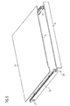
- FIG 1 illustrates a schematic perspective view of an oven door 10 according to a first embodiment of the present invention.
- said oven door 10 is provided for closing and opening an oven cavity of a cooking oven.
- the oven door 10 is pivoting around a horizontal axis, wherein said horizontal axis is arranged below or in a lower portion of an opening of the oven cavity.
- the oven door 10 comprises a front panel 12, an inner glass panel 14 and a door frame 20.
- the door frame 20 is substantially arranged between the inner glass panel 14 and the front panel 12.
- the door frame 20 includes an upper frame part 24 and two lateral frame parts 26.
- the height and width of the front panel 12 are bigger than the height and width of the inner glass panel 14.
- the oven door 10 comprises a door handle 22 attached at an outer side of the front panel 12.
- a ventilation opening 30 is formed as a cut-out in the upper portion of the inner glass panel 14.
- the ventilation opening 30 is formed as longitudinal cut-out extending along a horizontal direction.
- the ventilation opening 30 is formed as a gap between the inner glass panel 14 and the upper frame part 24 of the door frame 20.
- the upper frame part 24 and the two lateral frame parts 26 are made of metal.
- the upper frame part 24 and the two lateral frame parts 26 are made of stainless steel.
- the inner glass panel 14 is made of borosilicate glass.
- FIG 2 illustrates a schematic exploded perspective view of the oven door 10 according to the first embodiment of the present invention.
- the oven door 10 comprises the front panel 12, the inner glass panel 14 and the door frame 20.
- the door frame 20 includes the upper frame part 24 and the both lateral frame parts 26.
- Two door columns 28 are attached at the inner side of the front panel 12.
- the door columns 28 extend vertically in the mounted and closed state of the oven door.
- the door columns 28 are permanently attached at the front panel 12.
- the door frame 20 and the inner glass panel 14 form a first unit, which is attachable at the door columns 28.
- the front panel 12 and the door columns 28 form a second unit.
- Each lateral frame part 26 includes at least one notch 32, while each door column 28 includes at least one corresponding snapping hook 34.
- each lateral frame part 26 includes one notch 32, and each door column 28 includes one snapping hook 34.
- the notch 32 of the lateral frame part 26 and the corresponding snapping hook 34 of the door column 28 form a snap-in mechanism.
- the first unit and the second unit are connectable by the snap-in mechanism.
- an outer intermediate glass panel 16 and an inner intermediate glass panel 18 are arranged between the inner glass panel 14 and the front panel 12.
- the outer intermediate glass panel 16 and the inner intermediate glass panel 18 are arranged between the door columns 28.
- the width of the inner glass panel 14 is bigger than the widths of the outer intermediate glass panel 16 and inner intermediate glass panel 18.
- the oven door comprises two intermediate glass panels 16 and 18.
- the oven door may comprise one or more intermediate glass panels.
- FIG 3 illustrates a schematic perspective view of the oven door 10 according to a second embodiment of the present invention.
- the oven door 10 according to the second embodiment is similar as the oven door 10 of the first embodiment.
- the oven door 10 comprises the front panel 12, the inner glass panel 14 and the door frame 20.
- the door frame 20 is substantially arranged between the inner glass panel 14 and the front panel 12.
- the door frame 20 includes the upper frame part 24 and two lateral frame parts 26.
- the height and width of the front panel 12 are bigger than the height and width of the inner glass panel 14.
- the oven door 10 comprises the door handle 22 attached at an outer side of the front panel 12.
- the ventilation opening 30 is formed as the cut-out in the upper portion of the inner glass panel 14, wherein said ventilation opening 30 is formed as longitudinal cut-out extending along a horizontal direction.
- the ventilation opening 30 is formed as the gap between the inner glass panel 14 and the upper frame part 24 of the door frame 20.
- the upper frame part 24 of the glass frame 20 is made of glass, while the two lateral frame parts 26 are made of metal.
- the inner glass panel 14 and the upper frame part 24 are made of borosilicate glass.
- the lateral frame parts 26 are made of stainless steel.
- FIG 4 illustrates a schematic perspective view of the inner glass panel 14 and the door frame 20 for the oven door 10 according to the second embodiment of the present invention.
- the inner glass panel 14 and the door frame 20 form the first unit.
- the door frame 20 is permanently attached at the inner glass panel 14.
- the lateral frame parts 26 are attached at the outer side of the inner glass panel 14.
- the upper frame part 24 is attached at the upper ends of said lateral frame parts 26.
- the ventilation opening 30 is formed as the cut-out in the upper portion of the inner glass panel 14.
- the ventilation opening 30 extends over the central upper portion of the inner glass panel 14.
- the width of the ventilation opening 30 is marginally smaller than the width of the inner glass panel 14.
- the lateral portions of the inner glass panel 14 have the full height of said inner glass panel 14.
- the central portion of the inner glass panel 14 has a reduced height of said inner glass panel 14.
- FIG 5 illustrates a schematic exploded perspective view of the inner glass panel 14 and the door frame 20 for the oven door 10 according to the second embodiment of the present invention.
- the lateral frame parts 26 are attached at the outer side of the inner glass panel 14.
- the lateral frame parts 26 are glued on the outer side of the inner glass panel 14.
- the upper frame part 24 is attached at the upper ends of said lateral frame parts 26.
- the upper frame part 24 is glued on the upper ends of the lateral frame parts 26.
- the longitudinal ventilation opening 30 extend horizontally between the inner glass panel 14 and the upper frame part 24.
- the ventilation opening 30 extends over the central upper portion of the first unit.
- the width of the ventilation opening 30 is marginally smaller than the widths of the inner glass panel 14 and the upper frame part 26.
- the lateral portions of the inner glass panel 14 have the full height of said inner glass panel 14, while the central portion of the inner glass panel 14 has a reduced height of said inner glass panel 14.
- FIG 6 illustrates a schematic sectional side view of an upper portion of the oven door 10 according to the first embodiment of the present invention.
- the door handle 22 is attached at the outer side of the front panel 12.
- the door columns 28 are attached at the inner side of the front panel 12.
- the front panel 12 and the door columns 28 form the first unit.
- the lateral frame parts 26 are attached at the outer side of the inner glass panel 14.
- the upper frame part 24 is attached at the upper ends of said lateral frame parts 26.
- the inner glass panel 14 and the door frame 20 including the upper frame part 24 and the lateral frame parts 26 form the second unit.
- the first unit and second unit are connected by the snap-in mechanism between the lateral frame part 26 and door columns 28.
- FIG 6 clarifies that the inner side of the upper frame part 24 is in the same plane as the inner side of the inner glass panel 14.
- FIG 7 illustrates a schematic sectional side view of the upper portion of the oven door 10 according to a third embodiment of the present invention arranged at the cooking oven 36.
- the oven door 10 is in the closed state.
- the oven door 10 comprises the front panel 12, the inner glass panel 14 and the door frame 20.
- the door frame 20 includes the upper frame part 24 and the two lateral frame parts 26.
- the height and width of the front panel 12 are bigger than the height and width of the inner glass panel 14.
- the oven door 10 comprises the door handle 22 attached at the outer side of the front panel 12.
- the outer intermediate glass panel 16 and the inner intermediate glass panel 18 are arranged between the inner glass panel 14 and the front panel 12.
- the ventilation opening 30 is arranged between the inner glass panel 14 and the upper frame part 24.
- the oven door 10 is attached at the cooking oven 36.
- the oven door 10 is in the closed state.
- the cooking oven 36 comprises the oven cavity 40, a front frame 38 and an air channel 42.
- the front frame 38 encloses the front opening of the oven cavity 40.
- the air channel 42 is arranged above the oven cavity 40.
- the air channel 42 includes a suction hole 44 and an exhaust opening 46.
- the ventilation opening 30 of the oven door 10 is arranged in front of the suction hole 44 of the air channel 42.
- the air channel 42 effects an air stream inside the oven door 10.
- the front panel 12 is cooled-down by said air stream.
- the oven cavity 40 on the one hand and the air channel 42, the suction hole 44, the exhaust opening 48 and the ventilation opening 30 on the other hand are separated by a gasket 48.
- the oven door 10 according to the third embodiment is similar as the oven door 10 of the first embodiment.
- the oven door 10 of the third embodiment differs from that of the first embodiment in that the upper frame part 24 protrudes at the inner side of the oven door 10.
- the inner side of the upper frame part 24 is closer to the front frame 38 of the cooking oven 36 as the inner glass panel 14.
- the upper frame part 24 includes an appendix 50. Said appendix 50 forms the innermost part of the upper portion of the oven door 10.
- the appendix 50 improves the spatial separation between the suction hole 44 and the exhaust opening 46. This avoids a bypass between the suction hole 44 and the exhaust opening 46.
- the oven door 10 is suitable for pyrolytic cleanings.
- the inner glass panel 14 is made of a sufficiently heat resistant material, in particular borosilicate glass.
- the lower side and the lateral sides of the ventilation opening 30 are bordered by the inner glass panel 14 made of heat resistant material.
- the upper side of the ventilation opening 30 is bordered by the upper frame part 24 of the door frame 20.
- the upper frame part 24 is made of steel or glass, preferably stainless steel or borosilicate glass, respectively.
- the inner side of the upper frame part 24 is in the same plane as the inner side of the inner glass panel 14.
- the inner side of the upper frame part 24 protrudes and includes the appendix 50.
- Metal and glass, in particular stainless steel and borosilicate glass have similar thermal expansion coefficients.
- the contact between the inner glass panel 14 and the metallic parts of the door frame 20 allows a substantially uniform heat distribution at the inner glass panel 14, so that a bending of the inner glass panel 14 is avoided.
Landscapes
- Engineering & Computer Science (AREA)
- Chemical & Material Sciences (AREA)
- Combustion & Propulsion (AREA)
- Mechanical Engineering (AREA)
- General Engineering & Computer Science (AREA)
- Electric Ovens (AREA)
Priority Applications (4)
| Application Number | Priority Date | Filing Date | Title |
|---|---|---|---|
| EP15177181.3A EP3118525B1 (fr) | 2015-07-17 | 2015-07-17 | Porte de four pour une cavité de four d'un four de cuisson |
| US15/740,037 US20180187900A1 (en) | 2015-07-17 | 2016-06-27 | Oven door for an oven cavity of a cooking oven |
| PCT/EP2016/064872 WO2017012830A1 (fr) | 2015-07-17 | 2016-06-27 | Porte de four pour cavité de four d'un four de cuisson |
| AU2016296049A AU2016296049B2 (en) | 2015-07-17 | 2016-06-27 | Oven door for an oven cavity of a cooking oven |
Applications Claiming Priority (1)
| Application Number | Priority Date | Filing Date | Title |
|---|---|---|---|
| EP15177181.3A EP3118525B1 (fr) | 2015-07-17 | 2015-07-17 | Porte de four pour une cavité de four d'un four de cuisson |
Publications (2)
| Publication Number | Publication Date |
|---|---|
| EP3118525A1 true EP3118525A1 (fr) | 2017-01-18 |
| EP3118525B1 EP3118525B1 (fr) | 2018-03-21 |
Family
ID=53673810
Family Applications (1)
| Application Number | Title | Priority Date | Filing Date |
|---|---|---|---|
| EP15177181.3A Active EP3118525B1 (fr) | 2015-07-17 | 2015-07-17 | Porte de four pour une cavité de four d'un four de cuisson |
Country Status (4)
| Country | Link |
|---|---|
| US (1) | US20180187900A1 (fr) |
| EP (1) | EP3118525B1 (fr) |
| AU (1) | AU2016296049B2 (fr) |
| WO (1) | WO2017012830A1 (fr) |
Cited By (2)
| Publication number | Priority date | Publication date | Assignee | Title |
|---|---|---|---|---|
| CN107692860A (zh) * | 2017-09-28 | 2018-02-16 | 广东美的厨房电器制造有限公司 | 烹饪装置 |
| CN115992959A (zh) * | 2023-01-09 | 2023-04-21 | 杭州老板电器股份有限公司 | 一种燃烧器 |
Families Citing this family (2)
| Publication number | Priority date | Publication date | Assignee | Title |
|---|---|---|---|---|
| US10619862B2 (en) * | 2018-06-28 | 2020-04-14 | Whirlpool Corporation | Frontal cooling towers for a ventilation system of a cooking appliance |
| US12535223B2 (en) * | 2023-05-26 | 2026-01-27 | Whirlpool Corporation | Chambered air flow deflector for a door of a cooking oven |
Citations (4)
| Publication number | Priority date | Publication date | Assignee | Title |
|---|---|---|---|---|
| US4606324A (en) * | 1984-12-28 | 1986-08-19 | Mills Products, Inc. | Oven door |
| US20070251520A1 (en) * | 2006-04-24 | 2007-11-01 | Bang Suck J | Oven door |
| EP2090831A1 (fr) | 2008-02-13 | 2009-08-19 | Electrolux Home Products Corporation N.V. | Porte de four |
| US20130319396A1 (en) * | 2012-05-31 | 2013-12-05 | Bsh Home Appliances Corporation | Household appliance having a mounting system for a middle door glass |
Family Cites Families (4)
| Publication number | Priority date | Publication date | Assignee | Title |
|---|---|---|---|---|
| US5235962A (en) * | 1992-09-08 | 1993-08-17 | Maytag Corporation | Forced circulation oven door |
| DE19703301C2 (de) * | 1997-01-30 | 2000-06-08 | Schott Glas | Gaskochgerät |
| DE10105543A1 (de) * | 2001-02-06 | 2002-08-08 | Bsh Bosch Siemens Hausgeraete | Gargerät mit Tür |
| KR100698204B1 (ko) * | 2005-12-12 | 2007-03-22 | 엘지전자 주식회사 | 전기 오븐 레인지 |
-
2015
- 2015-07-17 EP EP15177181.3A patent/EP3118525B1/fr active Active
-
2016
- 2016-06-27 AU AU2016296049A patent/AU2016296049B2/en active Active
- 2016-06-27 US US15/740,037 patent/US20180187900A1/en not_active Abandoned
- 2016-06-27 WO PCT/EP2016/064872 patent/WO2017012830A1/fr not_active Ceased
Patent Citations (4)
| Publication number | Priority date | Publication date | Assignee | Title |
|---|---|---|---|---|
| US4606324A (en) * | 1984-12-28 | 1986-08-19 | Mills Products, Inc. | Oven door |
| US20070251520A1 (en) * | 2006-04-24 | 2007-11-01 | Bang Suck J | Oven door |
| EP2090831A1 (fr) | 2008-02-13 | 2009-08-19 | Electrolux Home Products Corporation N.V. | Porte de four |
| US20130319396A1 (en) * | 2012-05-31 | 2013-12-05 | Bsh Home Appliances Corporation | Household appliance having a mounting system for a middle door glass |
Cited By (3)
| Publication number | Priority date | Publication date | Assignee | Title |
|---|---|---|---|---|
| CN107692860A (zh) * | 2017-09-28 | 2018-02-16 | 广东美的厨房电器制造有限公司 | 烹饪装置 |
| CN115992959A (zh) * | 2023-01-09 | 2023-04-21 | 杭州老板电器股份有限公司 | 一种燃烧器 |
| CN115992959B (zh) * | 2023-01-09 | 2025-07-15 | 杭州老板电器股份有限公司 | 一种燃烧器 |
Also Published As
| Publication number | Publication date |
|---|---|
| WO2017012830A1 (fr) | 2017-01-26 |
| US20180187900A1 (en) | 2018-07-05 |
| EP3118525B1 (fr) | 2018-03-21 |
| AU2016296049A1 (en) | 2017-11-30 |
| AU2016296049B2 (en) | 2021-07-22 |
Similar Documents
| Publication | Publication Date | Title |
|---|---|---|
| US7874289B2 (en) | Door assembly for a cooking appliance | |
| EP2949179B1 (fr) | Four à micro-ondes ou four multifonction avec fonction de chauffage à micro-ondes | |
| US9004623B2 (en) | Door for a domestic appliance | |
| EP3118525B1 (fr) | Porte de four pour une cavité de four d'un four de cuisson | |
| US20130019854A1 (en) | Oven door | |
| EP1360440B1 (fr) | Appareil de cuisson muni d'une porte | |
| WO2015165499A1 (fr) | Porte destinée à un four, pouvant être démontée/remontée plus facilement | |
| US10688327B2 (en) | Oven appliance and a flame arrester for an oven appliance | |
| US9016270B2 (en) | Window mounting for thermal expansion in an oven appliance | |
| CA2426073A1 (fr) | Porte de four | |
| EP0549933A1 (fr) | Porte de four | |
| EP2627951B1 (fr) | Four de cuisson amélioré, en particulier à usage domestique | |
| AU2009320240B2 (en) | Cooking apparatus with protective shield | |
| EP2090831B1 (fr) | Porte de four | |
| EP2459935A2 (fr) | Four de cuisson, en particulier à usage ménager | |
| US20140251301A1 (en) | Oven appliance | |
| EP1818620B1 (fr) | Four ayant un chariot de four avec un elément chauffant intégré et des grilles de cuisson | |
| WO2015096865A1 (fr) | Porte destinée à être utilisée dans un appareil électroménager et appareil électroménager comprenant celle-ci | |
| WO2017211382A1 (fr) | Four avec porte comprenant un passage d'air | |
| EP2877785B1 (fr) | Dispositif de cuisson comprenant un ventilateur de refroidissement | |
| EP2340400B1 (fr) | Four comprenant une porte dont la température est maintenue à un niveau sans danger | |
| JP6091244B2 (ja) | 加熱調理器 | |
| EP3340739B1 (fr) | Porte de four à micro-ondes | |
| KR101180533B1 (ko) | 다층오븐 도어구조 | |
| ITTO20090590A1 (it) | Forno di cottura, in particolare di uso domestico |
Legal Events
| Date | Code | Title | Description |
|---|---|---|---|
| PUAI | Public reference made under article 153(3) epc to a published international application that has entered the european phase |
Free format text: ORIGINAL CODE: 0009012 |
|
| AK | Designated contracting states |
Kind code of ref document: A1 Designated state(s): AL AT BE BG CH CY CZ DE DK EE ES FI FR GB GR HR HU IE IS IT LI LT LU LV MC MK MT NL NO PL PT RO RS SE SI SK SM TR |
|
| AX | Request for extension of the european patent |
Extension state: BA ME |
|
| 17P | Request for examination filed |
Effective date: 20170718 |
|
| RBV | Designated contracting states (corrected) |
Designated state(s): AL AT BE BG CH CY CZ DE DK EE ES FI FR GB GR HR HU IE IS IT LI LT LU LV MC MK MT NL NO PL PT RO RS SE SI SK SM TR |
|
| RIC1 | Information provided on ipc code assigned before grant |
Ipc: F24C 15/04 20060101ALI20170831BHEP Ipc: F24C 15/00 20060101AFI20170831BHEP |
|
| GRAP | Despatch of communication of intention to grant a patent |
Free format text: ORIGINAL CODE: EPIDOSNIGR1 |
|
| INTG | Intention to grant announced |
Effective date: 20171011 |
|
| GRAS | Grant fee paid |
Free format text: ORIGINAL CODE: EPIDOSNIGR3 |
|
| GRAA | (expected) grant |
Free format text: ORIGINAL CODE: 0009210 |
|
| AK | Designated contracting states |
Kind code of ref document: B1 Designated state(s): AL AT BE BG CH CY CZ DE DK EE ES FI FR GB GR HR HU IE IS IT LI LT LU LV MC MK MT NL NO PL PT RO RS SE SI SK SM TR |
|
| REG | Reference to a national code |
Ref country code: GB Ref legal event code: FG4D |
|
| REG | Reference to a national code |
Ref country code: CH Ref legal event code: EP |
|
| REG | Reference to a national code |
Ref country code: AT Ref legal event code: REF Ref document number: 981521 Country of ref document: AT Kind code of ref document: T Effective date: 20180415 |
|
| REG | Reference to a national code |
Ref country code: IE Ref legal event code: FG4D |
|
| REG | Reference to a national code |
Ref country code: DE Ref legal event code: R096 Ref document number: 602015008995 Country of ref document: DE |
|
| REG | Reference to a national code |
Ref country code: NL Ref legal event code: MP Effective date: 20180321 |
|
| REG | Reference to a national code |
Ref country code: FR Ref legal event code: PLFP Year of fee payment: 4 |
|
| PG25 | Lapsed in a contracting state [announced via postgrant information from national office to epo] |
Ref country code: CY Free format text: LAPSE BECAUSE OF FAILURE TO SUBMIT A TRANSLATION OF THE DESCRIPTION OR TO PAY THE FEE WITHIN THE PRESCRIBED TIME-LIMIT Effective date: 20180321 Ref country code: LT Free format text: LAPSE BECAUSE OF FAILURE TO SUBMIT A TRANSLATION OF THE DESCRIPTION OR TO PAY THE FEE WITHIN THE PRESCRIBED TIME-LIMIT Effective date: 20180321 Ref country code: HR Free format text: LAPSE BECAUSE OF FAILURE TO SUBMIT A TRANSLATION OF THE DESCRIPTION OR TO PAY THE FEE WITHIN THE PRESCRIBED TIME-LIMIT Effective date: 20180321 Ref country code: NO Free format text: LAPSE BECAUSE OF FAILURE TO SUBMIT A TRANSLATION OF THE DESCRIPTION OR TO PAY THE FEE WITHIN THE PRESCRIBED TIME-LIMIT Effective date: 20180621 Ref country code: FI Free format text: LAPSE BECAUSE OF FAILURE TO SUBMIT A TRANSLATION OF THE DESCRIPTION OR TO PAY THE FEE WITHIN THE PRESCRIBED TIME-LIMIT Effective date: 20180321 |
|
| REG | Reference to a national code |
Ref country code: LT Ref legal event code: MG4D |
|
| REG | Reference to a national code |
Ref country code: AT Ref legal event code: MK05 Ref document number: 981521 Country of ref document: AT Kind code of ref document: T Effective date: 20180321 |
|
| PG25 | Lapsed in a contracting state [announced via postgrant information from national office to epo] |
Ref country code: GR Free format text: LAPSE BECAUSE OF FAILURE TO SUBMIT A TRANSLATION OF THE DESCRIPTION OR TO PAY THE FEE WITHIN THE PRESCRIBED TIME-LIMIT Effective date: 20180622 Ref country code: RS Free format text: LAPSE BECAUSE OF FAILURE TO SUBMIT A TRANSLATION OF THE DESCRIPTION OR TO PAY THE FEE WITHIN THE PRESCRIBED TIME-LIMIT Effective date: 20180321 Ref country code: SE Free format text: LAPSE BECAUSE OF FAILURE TO SUBMIT A TRANSLATION OF THE DESCRIPTION OR TO PAY THE FEE WITHIN THE PRESCRIBED TIME-LIMIT Effective date: 20180321 Ref country code: LV Free format text: LAPSE BECAUSE OF FAILURE TO SUBMIT A TRANSLATION OF THE DESCRIPTION OR TO PAY THE FEE WITHIN THE PRESCRIBED TIME-LIMIT Effective date: 20180321 Ref country code: BG Free format text: LAPSE BECAUSE OF FAILURE TO SUBMIT A TRANSLATION OF THE DESCRIPTION OR TO PAY THE FEE WITHIN THE PRESCRIBED TIME-LIMIT Effective date: 20180621 |
|
| PG25 | Lapsed in a contracting state [announced via postgrant information from national office to epo] |
Ref country code: PL Free format text: LAPSE BECAUSE OF FAILURE TO SUBMIT A TRANSLATION OF THE DESCRIPTION OR TO PAY THE FEE WITHIN THE PRESCRIBED TIME-LIMIT Effective date: 20180321 Ref country code: AL Free format text: LAPSE BECAUSE OF FAILURE TO SUBMIT A TRANSLATION OF THE DESCRIPTION OR TO PAY THE FEE WITHIN THE PRESCRIBED TIME-LIMIT Effective date: 20180321 Ref country code: ES Free format text: LAPSE BECAUSE OF FAILURE TO SUBMIT A TRANSLATION OF THE DESCRIPTION OR TO PAY THE FEE WITHIN THE PRESCRIBED TIME-LIMIT Effective date: 20180321 Ref country code: NL Free format text: LAPSE BECAUSE OF FAILURE TO SUBMIT A TRANSLATION OF THE DESCRIPTION OR TO PAY THE FEE WITHIN THE PRESCRIBED TIME-LIMIT Effective date: 20180321 Ref country code: RO Free format text: LAPSE BECAUSE OF FAILURE TO SUBMIT A TRANSLATION OF THE DESCRIPTION OR TO PAY THE FEE WITHIN THE PRESCRIBED TIME-LIMIT Effective date: 20180321 Ref country code: EE Free format text: LAPSE BECAUSE OF FAILURE TO SUBMIT A TRANSLATION OF THE DESCRIPTION OR TO PAY THE FEE WITHIN THE PRESCRIBED TIME-LIMIT Effective date: 20180321 |
|
| PG25 | Lapsed in a contracting state [announced via postgrant information from national office to epo] |
Ref country code: SM Free format text: LAPSE BECAUSE OF FAILURE TO SUBMIT A TRANSLATION OF THE DESCRIPTION OR TO PAY THE FEE WITHIN THE PRESCRIBED TIME-LIMIT Effective date: 20180321 Ref country code: CZ Free format text: LAPSE BECAUSE OF FAILURE TO SUBMIT A TRANSLATION OF THE DESCRIPTION OR TO PAY THE FEE WITHIN THE PRESCRIBED TIME-LIMIT Effective date: 20180321 Ref country code: AT Free format text: LAPSE BECAUSE OF FAILURE TO SUBMIT A TRANSLATION OF THE DESCRIPTION OR TO PAY THE FEE WITHIN THE PRESCRIBED TIME-LIMIT Effective date: 20180321 Ref country code: SK Free format text: LAPSE BECAUSE OF FAILURE TO SUBMIT A TRANSLATION OF THE DESCRIPTION OR TO PAY THE FEE WITHIN THE PRESCRIBED TIME-LIMIT Effective date: 20180321 |
|
| PG25 | Lapsed in a contracting state [announced via postgrant information from national office to epo] |
Ref country code: PT Free format text: LAPSE BECAUSE OF FAILURE TO SUBMIT A TRANSLATION OF THE DESCRIPTION OR TO PAY THE FEE WITHIN THE PRESCRIBED TIME-LIMIT Effective date: 20180723 |
|
| REG | Reference to a national code |
Ref country code: DE Ref legal event code: R097 Ref document number: 602015008995 Country of ref document: DE |
|
| PLBE | No opposition filed within time limit |
Free format text: ORIGINAL CODE: 0009261 |
|
| STAA | Information on the status of an ep patent application or granted ep patent |
Free format text: STATUS: NO OPPOSITION FILED WITHIN TIME LIMIT |
|
| PG25 | Lapsed in a contracting state [announced via postgrant information from national office to epo] |
Ref country code: DK Free format text: LAPSE BECAUSE OF FAILURE TO SUBMIT A TRANSLATION OF THE DESCRIPTION OR TO PAY THE FEE WITHIN THE PRESCRIBED TIME-LIMIT Effective date: 20180321 |
|
| 26N | No opposition filed |
Effective date: 20190102 |
|
| REG | Reference to a national code |
Ref country code: CH Ref legal event code: PL |
|
| PG25 | Lapsed in a contracting state [announced via postgrant information from national office to epo] |
Ref country code: LU Free format text: LAPSE BECAUSE OF NON-PAYMENT OF DUE FEES Effective date: 20180717 Ref country code: MC Free format text: LAPSE BECAUSE OF FAILURE TO SUBMIT A TRANSLATION OF THE DESCRIPTION OR TO PAY THE FEE WITHIN THE PRESCRIBED TIME-LIMIT Effective date: 20180321 |
|
| REG | Reference to a national code |
Ref country code: BE Ref legal event code: MM Effective date: 20180731 |
|
| REG | Reference to a national code |
Ref country code: IE Ref legal event code: MM4A |
|
| PG25 | Lapsed in a contracting state [announced via postgrant information from national office to epo] |
Ref country code: CH Free format text: LAPSE BECAUSE OF NON-PAYMENT OF DUE FEES Effective date: 20180731 Ref country code: IE Free format text: LAPSE BECAUSE OF NON-PAYMENT OF DUE FEES Effective date: 20180717 Ref country code: LI Free format text: LAPSE BECAUSE OF NON-PAYMENT OF DUE FEES Effective date: 20180731 |
|
| PG25 | Lapsed in a contracting state [announced via postgrant information from national office to epo] |
Ref country code: SI Free format text: LAPSE BECAUSE OF FAILURE TO SUBMIT A TRANSLATION OF THE DESCRIPTION OR TO PAY THE FEE WITHIN THE PRESCRIBED TIME-LIMIT Effective date: 20180321 Ref country code: BE Free format text: LAPSE BECAUSE OF NON-PAYMENT OF DUE FEES Effective date: 20180731 |
|
| PG25 | Lapsed in a contracting state [announced via postgrant information from national office to epo] |
Ref country code: MT Free format text: LAPSE BECAUSE OF NON-PAYMENT OF DUE FEES Effective date: 20180717 |
|
| GBPC | Gb: european patent ceased through non-payment of renewal fee |
Effective date: 20190717 |
|
| PG25 | Lapsed in a contracting state [announced via postgrant information from national office to epo] |
Ref country code: TR Free format text: LAPSE BECAUSE OF FAILURE TO SUBMIT A TRANSLATION OF THE DESCRIPTION OR TO PAY THE FEE WITHIN THE PRESCRIBED TIME-LIMIT Effective date: 20180321 |
|
| PG25 | Lapsed in a contracting state [announced via postgrant information from national office to epo] |
Ref country code: GB Free format text: LAPSE BECAUSE OF NON-PAYMENT OF DUE FEES Effective date: 20190717 |
|
| PG25 | Lapsed in a contracting state [announced via postgrant information from national office to epo] |
Ref country code: MK Free format text: LAPSE BECAUSE OF NON-PAYMENT OF DUE FEES Effective date: 20180321 Ref country code: HU Free format text: LAPSE BECAUSE OF FAILURE TO SUBMIT A TRANSLATION OF THE DESCRIPTION OR TO PAY THE FEE WITHIN THE PRESCRIBED TIME-LIMIT; INVALID AB INITIO Effective date: 20150717 |
|
| PG25 | Lapsed in a contracting state [announced via postgrant information from national office to epo] |
Ref country code: IS Free format text: LAPSE BECAUSE OF FAILURE TO SUBMIT A TRANSLATION OF THE DESCRIPTION OR TO PAY THE FEE WITHIN THE PRESCRIBED TIME-LIMIT Effective date: 20180721 |
|
| PGFP | Annual fee paid to national office [announced via postgrant information from national office to epo] |
Ref country code: FR Payment date: 20220720 Year of fee payment: 8 |
|
| P01 | Opt-out of the competence of the unified patent court (upc) registered |
Effective date: 20230625 |
|
| PG25 | Lapsed in a contracting state [announced via postgrant information from national office to epo] |
Ref country code: FR Free format text: LAPSE BECAUSE OF NON-PAYMENT OF DUE FEES Effective date: 20230731 |
|
| PGFP | Annual fee paid to national office [announced via postgrant information from national office to epo] |
Ref country code: DE Payment date: 20250728 Year of fee payment: 11 |
|
| PGFP | Annual fee paid to national office [announced via postgrant information from national office to epo] |
Ref country code: IT Payment date: 20250721 Year of fee payment: 11 |