EP3119554B1 - Procédé et dispositif de revêtement uniforme d'un tuyau tissé métallique ou métallisé - Google Patents
Procédé et dispositif de revêtement uniforme d'un tuyau tissé métallique ou métallisé Download PDFInfo
- Publication number
- EP3119554B1 EP3119554B1 EP15708161.3A EP15708161A EP3119554B1 EP 3119554 B1 EP3119554 B1 EP 3119554B1 EP 15708161 A EP15708161 A EP 15708161A EP 3119554 B1 EP3119554 B1 EP 3119554B1
- Authority
- EP
- European Patent Office
- Prior art keywords
- solder
- braided hose
- tube
- hose
- cavity
- Prior art date
- Legal status (The legal status is an assumption and is not a legal conclusion. Google has not performed a legal analysis and makes no representation as to the accuracy of the status listed.)
- Active
Links
Images



Classifications
-
- B—PERFORMING OPERATIONS; TRANSPORTING
- B23—MACHINE TOOLS; METAL-WORKING NOT OTHERWISE PROVIDED FOR
- B23K—SOLDERING OR UNSOLDERING; WELDING; CLADDING OR PLATING BY SOLDERING OR WELDING; CUTTING BY APPLYING HEAT LOCALLY, e.g. FLAME CUTTING; WORKING BY LASER BEAM
- B23K1/00—Soldering, e.g. brazing, or unsoldering
- B23K1/0008—Soldering, e.g. brazing, or unsoldering specially adapted for particular articles or work
-
- B—PERFORMING OPERATIONS; TRANSPORTING
- B23—MACHINE TOOLS; METAL-WORKING NOT OTHERWISE PROVIDED FOR
- B23K—SOLDERING OR UNSOLDERING; WELDING; CLADDING OR PLATING BY SOLDERING OR WELDING; CUTTING BY APPLYING HEAT LOCALLY, e.g. FLAME CUTTING; WORKING BY LASER BEAM
- B23K35/00—Rods, electrodes, materials, or media, for use in soldering, welding, or cutting
- B23K35/02—Rods, electrodes, materials, or media, for use in soldering, welding, or cutting characterised by mechanical features, e.g. shape
- B23K35/0222—Rods, electrodes, materials, or media, for use in soldering, welding, or cutting characterised by mechanical features, e.g. shape for use in soldering or brazing
-
- B—PERFORMING OPERATIONS; TRANSPORTING
- B23—MACHINE TOOLS; METAL-WORKING NOT OTHERWISE PROVIDED FOR
- B23K—SOLDERING OR UNSOLDERING; WELDING; CLADDING OR PLATING BY SOLDERING OR WELDING; CUTTING BY APPLYING HEAT LOCALLY, e.g. FLAME CUTTING; WORKING BY LASER BEAM
- B23K35/00—Rods, electrodes, materials, or media, for use in soldering, welding, or cutting
- B23K35/02—Rods, electrodes, materials, or media, for use in soldering, welding, or cutting characterised by mechanical features, e.g. shape
- B23K35/0222—Rods, electrodes, materials, or media, for use in soldering, welding, or cutting characterised by mechanical features, e.g. shape for use in soldering or brazing
- B23K35/0227—Rods or wires
-
- B—PERFORMING OPERATIONS; TRANSPORTING
- B23—MACHINE TOOLS; METAL-WORKING NOT OTHERWISE PROVIDED FOR
- B23K—SOLDERING OR UNSOLDERING; WELDING; CLADDING OR PLATING BY SOLDERING OR WELDING; CUTTING BY APPLYING HEAT LOCALLY, e.g. FLAME CUTTING; WORKING BY LASER BEAM
- B23K35/00—Rods, electrodes, materials, or media, for use in soldering, welding, or cutting
- B23K35/22—Rods, electrodes, materials, or media, for use in soldering, welding, or cutting characterised by the composition or nature of the material
- B23K35/36—Selection of non-metallic compositions, e.g. coatings or fluxes; Selection of soldering or welding materials, conjoint with selection of non-metallic compositions, both selections being of interest
-
- H—ELECTRICITY
- H01—ELECTRIC ELEMENTS
- H01B—CABLES; CONDUCTORS; INSULATORS; SELECTION OF MATERIALS FOR THEIR CONDUCTIVE, INSULATING OR DIELECTRIC PROPERTIES
- H01B1/00—Conductors or conductive bodies characterised by the conductive materials; Selection of materials as conductors
- H01B1/02—Conductors or conductive bodies characterised by the conductive materials; Selection of materials as conductors mainly consisting of metals or alloys
-
- H—ELECTRICITY
- H01—ELECTRIC ELEMENTS
- H01B—CABLES; CONDUCTORS; INSULATORS; SELECTION OF MATERIALS FOR THEIR CONDUCTIVE, INSULATING OR DIELECTRIC PROPERTIES
- H01B13/00—Apparatus or processes specially adapted for manufacturing conductors or cables
- H01B13/0036—Details
-
- H—ELECTRICITY
- H01—ELECTRIC ELEMENTS
- H01B—CABLES; CONDUCTORS; INSULATORS; SELECTION OF MATERIALS FOR THEIR CONDUCTIVE, INSULATING OR DIELECTRIC PROPERTIES
- H01B5/00—Non-insulated conductors or conductive bodies characterised by their form
- H01B5/12—Braided wires or the like
Definitions
- the invention relates to a method for the uniform coating of a metallic or metallized fabric tube with a solder or a solder and flux according to the preamble of claim 1 and an apparatus for performing the method according to claim 6.
- Known tape strands consist of a metallic fabric hose, in particular copper fabric, which is rolled to width and height according to customer requirements.
- Tape strands can be made using textile technologies, i. based on weaving, are manufactured and have a high flexibility and depending on the dimensions sufficient current carrying capacity or a low ohmic resistance.
- Stranded wire conductors are also used in electrical equipment and apparatus in particular when moving parts have to be contacted and / or in cases where there is a high mechanical vibration load.
- solder joints in the design of related contacts a ribbon conductor must be sufficiently tinned and provided with flux.
- known soldering techniques of soldering lead to insufficient adhesion in the preprocessing process or during soldering to undesired blistering.
- tinning in the liquid-tin bath often results in the disadvantage that the amount of tin is not sufficiently or irregularly distributed.
- flux must be applied separately in this case.
- a pre-tinned strand is not weldable, which is disadvantageous when a rigid mechanical contact or a connector or a similar means is applied by welding to the tape strand.
- a tube solder is previously known.
- This tube solder consists of a solder material in the form of a hollow wire.
- the hollow wire itself is filled with a soul of a special flux.
- Such a tube solder is very practical and easy to handle due to the flux integrated in the solder. Due to the tunable amount between solder material and flux is in each case an optimal ratio for the respective soldering process or taking into account the solder alloy available.
- solder for use in soldering comprising a solid form of a soft solder material, the outer surface is provided over part of the surface or over the entire surface with a firmly adherent and non-adhesive coating of a non-corrosive flux, according to DE 20 2007 002 140 U1 ,
- soldering tape is applied to the lead wire to be soldered before soldering.
- the solder ribbon itself is provided with a flux and is applied with the aid of a device by means of a mechanical bending operation on the connecting wire.
- solder alloy or the solder together with flux from the outside to a electrical conductor or contact is applied.
- This is quite expedient in conventional rigid conductors or stranded stranded conductors with the capillary forces acting in the latter case.
- stranded conductors however, the known techniques lead to problems with the consequence that additional solder deposits must be created or a Nachverzinnen is required.
- Another problem arises from the fact that pre-tinned tape strand materials can not be connected by welding to contacts, in particular vehicle plug contacts or the like.
- the object of the invention is achieved by a teaching according to the definition of claim 1 and device side by the feature combination according to claim 6.
- the process side is therefore assumed to be a uniform coating of a metallic or metallized fabric tube for electrical purposes with a solder or a solder flux.
- the uniform coating can be directly as a result of the process or a subsequent treatment step, in particular a heating of the solder or the solder alloy used.
- Decisive is the targeted provision a technologically optimal Lotmenge together with flux, without the actual soldering on a supplementary solder, which must be supplied separately, or another solder deposit must be used.
- the actual solder is provided in rod or tube form, wherein the outer diameter or the cross-sectional area of the rod or the solder tube is to be selected smaller than the inner diameter or the inner cross-sectional area of the fabric tube.
- the solder in rod or tube shape is then inserted into a longitudinal portion of the fabric tube cavity and fixed in the fabric tube cavity.
- a further known processing of the fabric tube in particular heating, can take place up to the melting point of the introduced solder.
- This heating process may have taken place during treatment of the tape strand fabric tube, but also only when using the fabric tube, e.g. for contacting a contact means on a vehicle window.
- a mandrel is used, which is introduced into an end-side opening region of the fabric tube or approximates this opening region, wherein the solder is introduced into the cavity via an opening located in the mandrel.
- solder with corresponding viscosity e.g. viscous over the mandrel, which acts as a nozzle in this case, enters the interior of the cavity of the fabric tube.
- the solder or solder-flux mixture has a paste-like form and is introduced into the paste tube in this pasty state and is subject to a certain degree of curing there.
- the fabric tube can be pushed over the rod-shaped or tubular solder, as it were in kinematic reversal. Subsequent to the above-described steps, a pressing or pressing force for deforming the fabric tube and fixing the solder can be applied to the fabric tube.
- the insertion of the solder and / or the opening of the cross-sectional area of the cavity of the fabric tube can be made compressed air assisted.
- a flux can be added to the solder.
- the flux is in a defined amount in the interior of the tube solder and forms its soul.
- At least one electrical contact can be connected to the fabric hose, in particular welded.
- the result is a metallic or metallized fabric hose, in particular a tape strand hose with befindliches inside the hose lot or Lot-flux amount, which extends over at least one hose longitudinal section.
- This quantity of solder flux is preferably a tube solder with the aforementioned flux core.
- a device which initially comprises a receiving unit for a metallic or metallized, electrically conductive fabric tube.
- a receiving unit for a metallic or metallized, electrically conductive fabric tube.
- At least one roller or press is provided for exerting a deformation force in order to obtain a firm mechanical bond between tube solder and fabric hose. Furthermore, means for cutting the created composite are present.
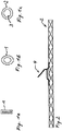
- the Fig. 1a shows a classic stripline 1 with a rectangular cross-section.
- the tape strand 1 can be brought into an imposed state, as the Fig. 1b shows.
- a stranded hose 2 according to Fig. 1c has a substantially circular cross section with a circular cavity 3.
- Fig. 2 can be seen as a schematic diagram, can be applied to the stranded hose 2, a rigid contact 4 by surface-side welding.
- Fig. 3 illustrates how a solder 5 in rod or tube shape, in particular a so-called tube solder, can be introduced by means of a Lotzu Industriesdorns 6 into the cavity 3 of the stranded hose 2.
- solder 5 is inserted via the mandrel 6, which has an opening 7, in the cavity 3 of the stranded hose 2 and pushed through the stranded hose 3.
- the stranded hose 2 is shaped into a final shape, e.g. Bandlitzenform with rectangular cross-section, transferred and this while the tube solder 5 fixed inside. At the points X can then take place a cutting of the stranded hose 2 in a conventional manner.
- a final shape e.g. Bandlitzenform with rectangular cross-section
- the desire of customers can be met to provide Bandlitzen prestigee for heating panels without Lötdepots for soldering of contacts on eg motor vehicle windows.
- the tape strand is completely provided with tin in the inner volume by welding, so that problem-free soldering is possible on the aforementioned vehicle window and the contact surface present there.
- a ribbon strand in the form of a copper mesh tube is pressed on the opposite ends as shown in the figure (see FIG Fig. 1b ) and pushed on the perforated guide pin or the mandrel tip. About the mandrel then the solder can be inserted diameter-adjusted in the copper fabric tube. Since the solder used is tube solder with flux, there is no so-called post-fluxing.
- the tube solder 5 is not continuously introduced into the stranded tube 2.
- the area in which the contact 4 is mounted, can remain free with respect to the tube solder 5.
- the tube solder 5 runs through the entire interior of the stranded tube 2, which is an advantage, for example, in the case of conventional soldering of the contact 4.
- a classic stranded hose 2 is provided, optionally after a corresponding expansion, in the interior with the tube solder 5.
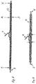
- the cross-sectional representation (right-hand illustration after Fig. 8 ) makes it clear that for easier insertion of the tube solder 5, a clearance between the outer diameter of the tube solder 5 and the inner diameter of the stranded tube 2 remains.
- the structure of stranded hose 2 is rolled with internal tube solder 5 by means of a pair of rollers 10 and 11 to width or by resorting to a lateral stop or a side roller, not shown in the figure on the width and height, ie subjected to a compression.
- the tube solder 5 securely fixed in the interior of the stranded hose 2 and on the other hand, the desired band structure of the stranded hose 2 can be generated.
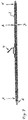
- Fig. 10 cut to length according to the technical or customer requirement and then stands as in the Fig. 11 shown as longitudinal and cross-sectional view, available for further processing.
Landscapes
- Engineering & Computer Science (AREA)
- Mechanical Engineering (AREA)
- Manufacturing & Machinery (AREA)
- Coating With Molten Metal (AREA)
Claims (6)
- Procédé de revêtement régulier d'une gaine en tissu métallique ou métallisé, par un apport de brasage ou un apport de brasage et un flux, dans lequel
l'apport de brasage est fourni en forme de barreau ou de tube (5), le diamètre extérieur ou la surface de section transversale du barreau ou du tube étant choisi(e) inférieur(e) au diamètre intérieur ou à la surface de section transversale intérieure de la gaine en tissu (1),
par introduction successive de l'apport de brasage (5) dans un creux (3) de la gaine en tissu, et ensuite
une force de pressage ou de pression (A ; B) est appliquée sur la gaine en tissu (1 ; 2) pour déformer la gaine en tissu (2) et pour fixer l'apport de brasage (5), afin d'obtenir ainsi la forme définitive de cordon en bande, et
par une poursuite connue en soi du traitement de la gaine en tissu (2), en particulier par échauffement jusqu'à un point de fusion de l'apport de brasage introduit,
caractérisé en ce que
la gaine en tissu (2) est chargée mécaniquement et évasée pour ouvrir le creux (3), et ainsi
un mandrin (6) est introduit dans la zone d'ouverture côté frontal de la gaine en tissu (1 ; 2) pour l'introduction de l'apport de brasage (5), et
via une ouverture (7) située dans le mandrin (6), l'apport de brasage (5) est introduit dans le creux (3), et l'introduction de l'apport de brasage (5) ne s'effectue pas en continu, mais de manière à laisser dégagée une zone d'un contact. - Procédé selon la revendication précédente,
caractérisé en ce que
l'introduction de l'apport de brasage (5) s'effectue en étant assisté par de l'air comprimé. - Procédé selon l'une des revendications précédentes,
caractérisé en ce que
un flux est mélangé avec ou ajouté à l'apport de brasage. - Procédé selon l'une des revendications précédentes,
caractérisé en ce que
l'apport de brasage (5) en forme de tube présente un flux dans son intérieur. - Procédé selon l'une des revendications précédentes,
caractérisé en ce que
avant l'introduction de l'apport de brasage dans la gaine en tissu, au moins un contact électrique (4) est relié à la gaine en tissu (2), en particulier par soudage. - Dispositif pour mettre en oeuvre un procédé selon l'une des revendications 1 à 5,
caractérisé en ce que
il est prévu une unité de logement pour une gaine en tissu métallique ou métallisé (1 ; 2), qui libère une ouverture de section transversale d'une extrémité d'un creux de gaine (3),
il est prévu un mandrin d'alimentation en apport de brasage (6) dont une extrémité est susceptible d'être rapprochée de l'ouverture de section transversale,
en outre un apport de brasage en forme de tube peut être amené mécaniquement dans le creux de gaine (3) par l'intérieur du mandrin d'alimentation en apport de brasage (6), et l'application d'une force de déformation (A ; B) s'effectue au moyen d'au moins un rouleau ou d'une presse, afin d'obtenir un composite ferme entre l'apport de brasage en forme de tube (5) et la gaine en tissu (1 ; 2), ainsi que des moyens (X) pour mettre à longueur le composite.
Applications Claiming Priority (3)
| Application Number | Priority Date | Filing Date | Title |
|---|---|---|---|
| DE102014003904 | 2014-03-19 | ||
| DE102014005494.2A DE102014005494A1 (de) | 2014-03-19 | 2014-04-14 | Verfahren und Vorrichtung zum gleichmäßigen Beschichten eines metallischen oder metallisierten Gewerbeschlauches |
| PCT/EP2015/054054 WO2015139928A1 (fr) | 2014-03-19 | 2015-02-26 | Procédé et dispositif de revêtement uniforme d'un tuyau tissé métallique ou métallisé |
Publications (2)
| Publication Number | Publication Date |
|---|---|
| EP3119554A1 EP3119554A1 (fr) | 2017-01-25 |
| EP3119554B1 true EP3119554B1 (fr) | 2019-07-24 |
Family
ID=54053376
Family Applications (1)
| Application Number | Title | Priority Date | Filing Date |
|---|---|---|---|
| EP15708161.3A Active EP3119554B1 (fr) | 2014-03-19 | 2015-02-26 | Procédé et dispositif de revêtement uniforme d'un tuyau tissé métallique ou métallisé |
Country Status (7)
| Country | Link |
|---|---|
| US (1) | US20170087657A1 (fr) |
| EP (1) | EP3119554B1 (fr) |
| CN (1) | CN106102987B (fr) |
| DE (1) | DE102014005494A1 (fr) |
| MX (1) | MX2016011962A (fr) |
| RU (1) | RU2016140370A (fr) |
| WO (1) | WO2015139928A1 (fr) |
Family Cites Families (9)
| Publication number | Priority date | Publication date | Assignee | Title |
|---|---|---|---|---|
| US1980890A (en) * | 1934-01-05 | 1934-11-13 | Burt M Mcconnell | Ready-to-solder wire |
| EP0108590B1 (fr) * | 1982-11-08 | 1986-11-26 | BRITISH TELECOMMUNICATIONS public limited company | Fibres optiques de transmission |
| US4807799A (en) | 1988-06-01 | 1989-02-28 | Raychem Corporation | Device for applying solder |
| EP0711628A1 (fr) * | 1994-11-14 | 1996-05-15 | METHODE ELECTRONICS, Inc. | Conducteur allongé comportant un ruban de soudure dans le noyau |
| DE19636577C1 (de) | 1996-09-09 | 1998-04-09 | Siemens Matsushita Components | Verfahren zum Anlöten von Anschlußdrähten an keramische Bauelemente |
| US6730848B1 (en) * | 2001-06-29 | 2004-05-04 | Antaya Technologies Corporation | Techniques for connecting a lead to a conductor |
| DE202007002140U1 (de) | 2007-02-14 | 2007-04-05 | Stannol Gmbh | Lotmittel zur Verwendung beim Weichlöten |
| DE102009033406A1 (de) | 2009-07-15 | 2011-01-20 | Jl Goslar Gmbh & Co. Kg | Röhrenlot und Verfahren zu seiner Herstellung |
| CN102642096A (zh) * | 2011-02-18 | 2012-08-22 | 苏州宇邦新型材料有限公司 | 一种焊料和采用该焊料的涂锡焊带及其制备方法 |
-
2014
- 2014-04-14 DE DE102014005494.2A patent/DE102014005494A1/de not_active Ceased
-
2015
- 2015-02-26 RU RU2016140370A patent/RU2016140370A/ru unknown
- 2015-02-26 MX MX2016011962A patent/MX2016011962A/es unknown
- 2015-02-26 US US15/126,455 patent/US20170087657A1/en not_active Abandoned
- 2015-02-26 EP EP15708161.3A patent/EP3119554B1/fr active Active
- 2015-02-26 WO PCT/EP2015/054054 patent/WO2015139928A1/fr not_active Ceased
- 2015-02-26 CN CN201580014621.8A patent/CN106102987B/zh not_active Expired - Fee Related
Non-Patent Citations (1)
| Title |
|---|
| None * |
Also Published As
| Publication number | Publication date |
|---|---|
| CN106102987A (zh) | 2016-11-09 |
| EP3119554A1 (fr) | 2017-01-25 |
| RU2016140370A (ru) | 2018-04-20 |
| WO2015139928A1 (fr) | 2015-09-24 |
| DE102014005494A1 (de) | 2015-09-24 |
| MX2016011962A (es) | 2017-04-27 |
| CN106102987B (zh) | 2020-03-17 |
| US20170087657A1 (en) | 2017-03-30 |
Similar Documents
| Publication | Publication Date | Title |
|---|---|---|
| EP2553766B1 (fr) | Procédé de confection de câble et câble ainsi confectionné | |
| EP1771274B1 (fr) | Procede pour realiser un assemblage par soudure | |
| EP2962369B1 (fr) | Procédé pour réaliser un assemblage par liaison de matière sur une extrémité de câble et câble configuré | |
| DE10358686B4 (de) | Crimpkontaktelement | |
| EP2362491B1 (fr) | Procédé de connexion d'une conduite électrique avec un élément de raccordement électrique | |
| EP3602690B1 (fr) | Liaison d'une partie de raccordement à un câble toronné | |
| DE112011103488B4 (de) | Anschlussteil für einen elektrischen Leiter | |
| DE102018119844A1 (de) | Elektrische Verbindung sowie Verfahren zur Herstellung einer elektrischen Verbindung | |
| DE102013205235B4 (de) | Crimpverbindung sowie Crimpelement, Crimpvorrichtung und Verfahren zum Herstellen einer Crimpverbindung | |
| DE112014004195T5 (de) | Anschluss, Verbindungsstrukturkörper, und Verfahren zur Herstellung des Anschlusses | |
| WO2018206127A1 (fr) | Système de contact pour la mise en contact d'une tresse de blindage et d'un élément de contact | |
| DE112014006848T5 (de) | Verfahren zum Verbinden eines Anschlusselements und einer elektrischen Leitung und ein Verbindungsanschlusselement für eine elektrische Leitung | |
| DE10046489C1 (de) | Lötbares elektrisches Anschlußelement mit Lotdepot und dessen Verwendung | |
| EP2725659B1 (fr) | Manchon de câble coaxial | |
| DE102004044480A1 (de) | Verfahren zur Herstellung einer Schweißverbindung sowie Schweißverbindung | |
| DE3729490C3 (de) | Elektrisches Verbindungselement sowie Verfahren zum Verbinden elektrischer Drähte | |
| EP3119554B1 (fr) | Procédé et dispositif de revêtement uniforme d'un tuyau tissé métallique ou métallisé | |
| DE102015119473A1 (de) | Steckkontakt | |
| AT516232B1 (de) | Verfahren zur Verbindung eines Kabelendes mit einem Verbindungselement | |
| DE102018100020B4 (de) | Verfahren und Vorrichtung zur Herstellung einer Verbindung zwischen einem Crimpkontakt und einem Litzenleiter | |
| DE102016123936B4 (de) | Verfahren zur Herstellung eines Buchsenkontaktes | |
| EP2672569B1 (fr) | Procédé destiné à relier des conducteurs électriques et un faisceau conducteur | |
| DE102011088922A1 (de) | Verfahren und Vorrichtung zur Leiterinjektion, und Kontaktierverbindung | |
| DE102007047436B4 (de) | Crimpen mit Mittenaussparung | |
| DE102010039883B4 (de) | Steckkontaktteil für elektrische Anschlüsse und Verfahren zur Herstellung eines derartigen Steckkontaktteils |
Legal Events
| Date | Code | Title | Description |
|---|---|---|---|
| STAA | Information on the status of an ep patent application or granted ep patent |
Free format text: STATUS: THE INTERNATIONAL PUBLICATION HAS BEEN MADE |
|
| PUAI | Public reference made under article 153(3) epc to a published international application that has entered the european phase |
Free format text: ORIGINAL CODE: 0009012 |
|
| STAA | Information on the status of an ep patent application or granted ep patent |
Free format text: STATUS: REQUEST FOR EXAMINATION WAS MADE |
|
| 17P | Request for examination filed |
Effective date: 20160922 |
|
| AK | Designated contracting states |
Kind code of ref document: A1 Designated state(s): AL AT BE BG CH CY CZ DE DK EE ES FI FR GB GR HR HU IE IS IT LI LT LU LV MC MK MT NL NO PL PT RO RS SE SI SK SM TR |
|
| AX | Request for extension of the european patent |
Extension state: BA ME |
|
| DAX | Request for extension of the european patent (deleted) | ||
| STAA | Information on the status of an ep patent application or granted ep patent |
Free format text: STATUS: EXAMINATION IS IN PROGRESS |
|
| 17Q | First examination report despatched |
Effective date: 20180423 |
|
| GRAP | Despatch of communication of intention to grant a patent |
Free format text: ORIGINAL CODE: EPIDOSNIGR1 |
|
| STAA | Information on the status of an ep patent application or granted ep patent |
Free format text: STATUS: GRANT OF PATENT IS INTENDED |
|
| INTG | Intention to grant announced |
Effective date: 20190222 |
|
| GRAS | Grant fee paid |
Free format text: ORIGINAL CODE: EPIDOSNIGR3 |
|
| GRAA | (expected) grant |
Free format text: ORIGINAL CODE: 0009210 |
|
| STAA | Information on the status of an ep patent application or granted ep patent |
Free format text: STATUS: THE PATENT HAS BEEN GRANTED |
|
| AK | Designated contracting states |
Kind code of ref document: B1 Designated state(s): AL AT BE BG CH CY CZ DE DK EE ES FI FR GB GR HR HU IE IS IT LI LT LU LV MC MK MT NL NO PL PT RO RS SE SI SK SM TR |
|
| REG | Reference to a national code |
Ref country code: GB Ref legal event code: FG4D Free format text: NOT ENGLISH |
|
| REG | Reference to a national code |
Ref country code: CH Ref legal event code: EP |
|
| REG | Reference to a national code |
Ref country code: DE Ref legal event code: R096 Ref document number: 502015009742 Country of ref document: DE |
|
| REG | Reference to a national code |
Ref country code: AT Ref legal event code: REF Ref document number: 1157618 Country of ref document: AT Kind code of ref document: T Effective date: 20190815 |
|
| REG | Reference to a national code |
Ref country code: IE Ref legal event code: FG4D Free format text: LANGUAGE OF EP DOCUMENT: GERMAN |
|
| REG | Reference to a national code |
Ref country code: NL Ref legal event code: MP Effective date: 20190724 |
|
| REG | Reference to a national code |
Ref country code: LT Ref legal event code: MG4D |
|
| PG25 | Lapsed in a contracting state [announced via postgrant information from national office to epo] |
Ref country code: LT Free format text: LAPSE BECAUSE OF FAILURE TO SUBMIT A TRANSLATION OF THE DESCRIPTION OR TO PAY THE FEE WITHIN THE PRESCRIBED TIME-LIMIT Effective date: 20190724 Ref country code: HR Free format text: LAPSE BECAUSE OF FAILURE TO SUBMIT A TRANSLATION OF THE DESCRIPTION OR TO PAY THE FEE WITHIN THE PRESCRIBED TIME-LIMIT Effective date: 20190724 Ref country code: NO Free format text: LAPSE BECAUSE OF FAILURE TO SUBMIT A TRANSLATION OF THE DESCRIPTION OR TO PAY THE FEE WITHIN THE PRESCRIBED TIME-LIMIT Effective date: 20191024 Ref country code: SE Free format text: LAPSE BECAUSE OF FAILURE TO SUBMIT A TRANSLATION OF THE DESCRIPTION OR TO PAY THE FEE WITHIN THE PRESCRIBED TIME-LIMIT Effective date: 20190724 Ref country code: FI Free format text: LAPSE BECAUSE OF FAILURE TO SUBMIT A TRANSLATION OF THE DESCRIPTION OR TO PAY THE FEE WITHIN THE PRESCRIBED TIME-LIMIT Effective date: 20190724 Ref country code: BG Free format text: LAPSE BECAUSE OF FAILURE TO SUBMIT A TRANSLATION OF THE DESCRIPTION OR TO PAY THE FEE WITHIN THE PRESCRIBED TIME-LIMIT Effective date: 20191024 Ref country code: NL Free format text: LAPSE BECAUSE OF FAILURE TO SUBMIT A TRANSLATION OF THE DESCRIPTION OR TO PAY THE FEE WITHIN THE PRESCRIBED TIME-LIMIT Effective date: 20190724 Ref country code: PT Free format text: LAPSE BECAUSE OF FAILURE TO SUBMIT A TRANSLATION OF THE DESCRIPTION OR TO PAY THE FEE WITHIN THE PRESCRIBED TIME-LIMIT Effective date: 20191125 |
|
| PG25 | Lapsed in a contracting state [announced via postgrant information from national office to epo] |
Ref country code: IS Free format text: LAPSE BECAUSE OF FAILURE TO SUBMIT A TRANSLATION OF THE DESCRIPTION OR TO PAY THE FEE WITHIN THE PRESCRIBED TIME-LIMIT Effective date: 20191124 Ref country code: RS Free format text: LAPSE BECAUSE OF FAILURE TO SUBMIT A TRANSLATION OF THE DESCRIPTION OR TO PAY THE FEE WITHIN THE PRESCRIBED TIME-LIMIT Effective date: 20190724 Ref country code: AL Free format text: LAPSE BECAUSE OF FAILURE TO SUBMIT A TRANSLATION OF THE DESCRIPTION OR TO PAY THE FEE WITHIN THE PRESCRIBED TIME-LIMIT Effective date: 20190724 Ref country code: LV Free format text: LAPSE BECAUSE OF FAILURE TO SUBMIT A TRANSLATION OF THE DESCRIPTION OR TO PAY THE FEE WITHIN THE PRESCRIBED TIME-LIMIT Effective date: 20190724 Ref country code: ES Free format text: LAPSE BECAUSE OF FAILURE TO SUBMIT A TRANSLATION OF THE DESCRIPTION OR TO PAY THE FEE WITHIN THE PRESCRIBED TIME-LIMIT Effective date: 20190724 Ref country code: GR Free format text: LAPSE BECAUSE OF FAILURE TO SUBMIT A TRANSLATION OF THE DESCRIPTION OR TO PAY THE FEE WITHIN THE PRESCRIBED TIME-LIMIT Effective date: 20191025 |
|
| PG25 | Lapsed in a contracting state [announced via postgrant information from national office to epo] |
Ref country code: TR Free format text: LAPSE BECAUSE OF FAILURE TO SUBMIT A TRANSLATION OF THE DESCRIPTION OR TO PAY THE FEE WITHIN THE PRESCRIBED TIME-LIMIT Effective date: 20190724 |
|
| PG25 | Lapsed in a contracting state [announced via postgrant information from national office to epo] |
Ref country code: DK Free format text: LAPSE BECAUSE OF FAILURE TO SUBMIT A TRANSLATION OF THE DESCRIPTION OR TO PAY THE FEE WITHIN THE PRESCRIBED TIME-LIMIT Effective date: 20190724 Ref country code: PL Free format text: LAPSE BECAUSE OF FAILURE TO SUBMIT A TRANSLATION OF THE DESCRIPTION OR TO PAY THE FEE WITHIN THE PRESCRIBED TIME-LIMIT Effective date: 20190724 Ref country code: RO Free format text: LAPSE BECAUSE OF FAILURE TO SUBMIT A TRANSLATION OF THE DESCRIPTION OR TO PAY THE FEE WITHIN THE PRESCRIBED TIME-LIMIT Effective date: 20190724 Ref country code: EE Free format text: LAPSE BECAUSE OF FAILURE TO SUBMIT A TRANSLATION OF THE DESCRIPTION OR TO PAY THE FEE WITHIN THE PRESCRIBED TIME-LIMIT Effective date: 20190724 Ref country code: IT Free format text: LAPSE BECAUSE OF FAILURE TO SUBMIT A TRANSLATION OF THE DESCRIPTION OR TO PAY THE FEE WITHIN THE PRESCRIBED TIME-LIMIT Effective date: 20190724 |
|
| PGFP | Annual fee paid to national office [announced via postgrant information from national office to epo] |
Ref country code: DE Payment date: 20200228 Year of fee payment: 6 |
|
| PG25 | Lapsed in a contracting state [announced via postgrant information from national office to epo] |
Ref country code: SM Free format text: LAPSE BECAUSE OF FAILURE TO SUBMIT A TRANSLATION OF THE DESCRIPTION OR TO PAY THE FEE WITHIN THE PRESCRIBED TIME-LIMIT Effective date: 20190724 Ref country code: IS Free format text: LAPSE BECAUSE OF FAILURE TO SUBMIT A TRANSLATION OF THE DESCRIPTION OR TO PAY THE FEE WITHIN THE PRESCRIBED TIME-LIMIT Effective date: 20200224 Ref country code: CZ Free format text: LAPSE BECAUSE OF FAILURE TO SUBMIT A TRANSLATION OF THE DESCRIPTION OR TO PAY THE FEE WITHIN THE PRESCRIBED TIME-LIMIT Effective date: 20190724 Ref country code: SK Free format text: LAPSE BECAUSE OF FAILURE TO SUBMIT A TRANSLATION OF THE DESCRIPTION OR TO PAY THE FEE WITHIN THE PRESCRIBED TIME-LIMIT Effective date: 20190724 |
|
| REG | Reference to a national code |
Ref country code: DE Ref legal event code: R097 Ref document number: 502015009742 Country of ref document: DE |
|
| PLBE | No opposition filed within time limit |
Free format text: ORIGINAL CODE: 0009261 |
|
| STAA | Information on the status of an ep patent application or granted ep patent |
Free format text: STATUS: NO OPPOSITION FILED WITHIN TIME LIMIT |
|
| PG2D | Information on lapse in contracting state deleted |
Ref country code: IS |
|
| 26N | No opposition filed |
Effective date: 20200603 |
|
| PG25 | Lapsed in a contracting state [announced via postgrant information from national office to epo] |
Ref country code: SI Free format text: LAPSE BECAUSE OF FAILURE TO SUBMIT A TRANSLATION OF THE DESCRIPTION OR TO PAY THE FEE WITHIN THE PRESCRIBED TIME-LIMIT Effective date: 20190724 |
|
| REG | Reference to a national code |
Ref country code: CH Ref legal event code: PL |
|
| GBPC | Gb: european patent ceased through non-payment of renewal fee |
Effective date: 20200226 |
|
| REG | Reference to a national code |
Ref country code: BE Ref legal event code: MM Effective date: 20200229 |
|
| PG25 | Lapsed in a contracting state [announced via postgrant information from national office to epo] |
Ref country code: LU Free format text: LAPSE BECAUSE OF NON-PAYMENT OF DUE FEES Effective date: 20200226 Ref country code: MC Free format text: LAPSE BECAUSE OF FAILURE TO SUBMIT A TRANSLATION OF THE DESCRIPTION OR TO PAY THE FEE WITHIN THE PRESCRIBED TIME-LIMIT Effective date: 20190724 |
|
| PG25 | Lapsed in a contracting state [announced via postgrant information from national office to epo] |
Ref country code: CH Free format text: LAPSE BECAUSE OF NON-PAYMENT OF DUE FEES Effective date: 20200229 Ref country code: LI Free format text: LAPSE BECAUSE OF NON-PAYMENT OF DUE FEES Effective date: 20200229 |
|
| PG25 | Lapsed in a contracting state [announced via postgrant information from national office to epo] |
Ref country code: FR Free format text: LAPSE BECAUSE OF NON-PAYMENT OF DUE FEES Effective date: 20200229 Ref country code: GB Free format text: LAPSE BECAUSE OF NON-PAYMENT OF DUE FEES Effective date: 20200226 Ref country code: IE Free format text: LAPSE BECAUSE OF NON-PAYMENT OF DUE FEES Effective date: 20200226 |
|
| PG25 | Lapsed in a contracting state [announced via postgrant information from national office to epo] |
Ref country code: BE Free format text: LAPSE BECAUSE OF NON-PAYMENT OF DUE FEES Effective date: 20200229 |
|
| REG | Reference to a national code |
Ref country code: AT Ref legal event code: MM01 Ref document number: 1157618 Country of ref document: AT Kind code of ref document: T Effective date: 20200226 |
|
| PG25 | Lapsed in a contracting state [announced via postgrant information from national office to epo] |
Ref country code: AT Free format text: LAPSE BECAUSE OF NON-PAYMENT OF DUE FEES Effective date: 20200226 |
|
| REG | Reference to a national code |
Ref country code: DE Ref legal event code: R119 Ref document number: 502015009742 Country of ref document: DE |
|
| PG25 | Lapsed in a contracting state [announced via postgrant information from national office to epo] |
Ref country code: DE Free format text: LAPSE BECAUSE OF NON-PAYMENT OF DUE FEES Effective date: 20210901 |
|
| PG25 | Lapsed in a contracting state [announced via postgrant information from national office to epo] |
Ref country code: MT Free format text: LAPSE BECAUSE OF FAILURE TO SUBMIT A TRANSLATION OF THE DESCRIPTION OR TO PAY THE FEE WITHIN THE PRESCRIBED TIME-LIMIT Effective date: 20190724 Ref country code: CY Free format text: LAPSE BECAUSE OF FAILURE TO SUBMIT A TRANSLATION OF THE DESCRIPTION OR TO PAY THE FEE WITHIN THE PRESCRIBED TIME-LIMIT Effective date: 20190724 |
|
| PG25 | Lapsed in a contracting state [announced via postgrant information from national office to epo] |
Ref country code: MK Free format text: LAPSE BECAUSE OF FAILURE TO SUBMIT A TRANSLATION OF THE DESCRIPTION OR TO PAY THE FEE WITHIN THE PRESCRIBED TIME-LIMIT Effective date: 20190724 |
|
| P01 | Opt-out of the competence of the unified patent court (upc) registered |
Effective date: 20230621 |