EP3119598B1 - Dispositif de montage pour fixer un module de pneumatique - Google Patents
Dispositif de montage pour fixer un module de pneumatique Download PDFInfo
- Publication number
- EP3119598B1 EP3119598B1 EP15702772.3A EP15702772A EP3119598B1 EP 3119598 B1 EP3119598 B1 EP 3119598B1 EP 15702772 A EP15702772 A EP 15702772A EP 3119598 B1 EP3119598 B1 EP 3119598B1
- Authority
- EP
- European Patent Office
- Prior art keywords
- pneumatic
- placement head
- mounting device
- tire
- support arm
- Prior art date
- Legal status (The legal status is an assumption and is not a legal conclusion. Google has not performed a legal analysis and makes no representation as to the accuracy of the status listed.)
- Active
Links
Images

Classifications
-
- B—PERFORMING OPERATIONS; TRANSPORTING
- B29—WORKING OF PLASTICS; WORKING OF SUBSTANCES IN A PLASTIC STATE IN GENERAL
- B29D—PRODUCING PARTICULAR ARTICLES FROM PLASTICS OR FROM SUBSTANCES IN A PLASTIC STATE
- B29D30/00—Producing pneumatic or solid tyres or parts thereof
- B29D30/0061—Accessories, details or auxiliary operations not otherwise provided for
-
- B—PERFORMING OPERATIONS; TRANSPORTING
- B29—WORKING OF PLASTICS; WORKING OF SUBSTANCES IN A PLASTIC STATE IN GENERAL
- B29C—SHAPING OR JOINING OF PLASTICS; SHAPING OF MATERIAL IN A PLASTIC STATE, NOT OTHERWISE PROVIDED FOR; AFTER-TREATMENT OF THE SHAPED PRODUCTS, e.g. REPAIRING
- B29C65/00—Joining or sealing of preformed parts, e.g. welding of plastics materials; Apparatus therefor
- B29C65/02—Joining or sealing of preformed parts, e.g. welding of plastics materials; Apparatus therefor by heating, with or without pressure
- B29C65/18—Joining or sealing of preformed parts, e.g. welding of plastics materials; Apparatus therefor by heating, with or without pressure using heated tools
-
- B—PERFORMING OPERATIONS; TRANSPORTING
- B60—VEHICLES IN GENERAL
- B60C—VEHICLE TYRES; TYRE INFLATION; TYRE CHANGING; CONNECTING VALVES TO INFLATABLE ELASTIC BODIES IN GENERAL; DEVICES OR ARRANGEMENTS RELATED TO TYRES
- B60C23/00—Devices for measuring, signalling, controlling, or distributing tyre pressure or temperature, specially adapted for mounting on vehicles; Arrangement of tyre inflating devices on vehicles, e.g. of pumps or of tanks; Tyre cooling arrangements
- B60C23/02—Signalling devices actuated by tyre pressure
- B60C23/04—Signalling devices actuated by tyre pressure mounted on the wheel or tyre
- B60C23/0491—Constructional details of means for attaching the control device
- B60C23/0493—Constructional details of means for attaching the control device for attachment on the tyre
-
- H—ELECTRICITY
- H01—ELECTRIC ELEMENTS
- H01Q—ANTENNAS, i.e. RADIO AERIALS
- H01Q1/00—Details of, or arrangements associated with, antennas
- H01Q1/12—Supports; Mounting means
- H01Q1/22—Supports; Mounting means by structural association with other equipment or articles
- H01Q1/2208—Supports; Mounting means by structural association with other equipment or articles associated with components used in interrogation type services, i.e. in systems for information exchange between an interrogator/reader and a tag/transponder, e.g. in Radio Frequency Identification [RFID] systems
- H01Q1/2241—Supports; Mounting means by structural association with other equipment or articles associated with components used in interrogation type services, i.e. in systems for information exchange between an interrogator/reader and a tag/transponder, e.g. in Radio Frequency Identification [RFID] systems used in or for vehicle tyres
-
- H—ELECTRICITY
- H01—ELECTRIC ELEMENTS
- H01Q—ANTENNAS, i.e. RADIO AERIALS
- H01Q1/00—Details of, or arrangements associated with, antennas
- H01Q1/12—Supports; Mounting means
- H01Q1/22—Supports; Mounting means by structural association with other equipment or articles
- H01Q1/225—Supports; Mounting means by structural association with other equipment or articles used in level-measurement devices, e.g. for level gauge measurement
-
- B—PERFORMING OPERATIONS; TRANSPORTING
- B29—WORKING OF PLASTICS; WORKING OF SUBSTANCES IN A PLASTIC STATE IN GENERAL
- B29D—PRODUCING PARTICULAR ARTICLES FROM PLASTICS OR FROM SUBSTANCES IN A PLASTIC STATE
- B29D30/00—Producing pneumatic or solid tyres or parts thereof
- B29D30/0061—Accessories, details or auxiliary operations not otherwise provided for
- B29D2030/0072—Attaching fasteners to tyres, e.g. patches, in order to connect devices to tyres
-
- B—PERFORMING OPERATIONS; TRANSPORTING
- B29—WORKING OF PLASTICS; WORKING OF SUBSTANCES IN A PLASTIC STATE IN GENERAL
- B29L—INDEXING SCHEME ASSOCIATED WITH SUBCLASS B29C, RELATING TO PARTICULAR ARTICLES
- B29L2030/00—Pneumatic or solid tyres or parts thereof
-
- B—PERFORMING OPERATIONS; TRANSPORTING
- B29—WORKING OF PLASTICS; WORKING OF SUBSTANCES IN A PLASTIC STATE IN GENERAL
- B29L—INDEXING SCHEME ASSOCIATED WITH SUBCLASS B29C, RELATING TO PARTICULAR ARTICLES
- B29L2031/00—Other particular articles
- B29L2031/34—Electrical apparatus, e.g. sparking plugs or parts thereof
Definitions
- the invention relates to a mounting device for fastening a tire module, in particular a tire pressure sensor, to an inside of a pneumatic tire for vehicles, comprising a stand from which a support arm extends, with a force that can be specified on the longitudinal end of the support arm facing away from the stand lowerable setting head is attached.
- the US 2009/0165928 discloses a device for attaching an RFID patch to the inside of a tire.
- the device has a stand, from which a support arm extends, a mounting head being attached to the support arm and being movable in the direction of the inside of the tire.
- a holding device with openings is arranged on the setting head, which can create a vacuum for clamping the patch to the setting head.
- a device is known with which a sound-absorbing material can be applied to the inside of a vehicle tire.
- the device comprises a workbench on which the vehicle tire is fixed with the aid of brackets.
- the device has a three-armed working head which comprises a nozzle arm which sprays a primer for the adhesive on the inside of the vehicle tire, a cleaning arm which removes excess primer, and a stick-on setting arm which has the noise-insulating material applies the inside of the vehicle tire.
- the DE 10 2009 025 794 discloses a device for mounting tire modules on a vehicle tire, the device comprising a pressing means which allows a high degree of automation.
- the pressing means comprises an air line, with which a negative pressure is generated, with which the tire module is held securely in the pressing means.
- the air line can also create an overpressure to the To additionally strengthen the adhesive connection between the tire module and the surface of the vehicle tire.
- preconditioned air can optimize the gluing process via the air line.
- Tire modules for attachment to an inside of a pneumatic tire for vehicles are known from the prior art.
- the DE 10 2012 007 071 A1 such a tire module with a device for measuring and / or monitoring the air pressure in the tire, the device being cast and encapsulated with the aid of a casting compound and accommodated in a hat-shaped holder.
- the circumferential edge of the hat-shaped holder serves to fasten the tire module to the inside of the pneumatic tire and can be fastened to the inside, for example by gluing or vulcanizing.
- the problem with all known tire modules is their attachment to the inside of the pneumatic tire, since after a long period of operation the tire module detaches with the electronic device.
- the invention has for its object to provide a solution with a tire module in a structurally simple manner can be reproducibly attached to an inside of a pneumatic tire of a vehicle.
- the object is achieved according to the invention in that the tire module is hat-shaped, the setting head being a holding device with which the tire module can be releasably held on the setting head in a clamping manner, and at least one heating element for Cohesively connecting the tire module to the inside of the pneumatic tire, the support arm being pivotally mounted on the stand at its longitudinal end facing away from the setting head, at least one first pneumatic cylinder designed to raise the setting head and lower it with the predetermined force being arranged on the support arm, and wherein the setting head is designed as a hollow cylinder and the hat-shaped tire module is arranged pressed into the cavity of the setting head in such a way that a peripheral edge of the tire module and the underside of the hat-shaped tire module on a side facing away from the first pneumatic cylinder Longitudinal end of the setting head are arranged so that when the setting head is lowered, at least the peripheral edge of the hat-shaped tire module is pressed
- the invention provides an assembly device for attaching a tire module, such as a tire pressure sensor, to the inside of a pneumatic tire, which is characterized by a functionally appropriate construction and has a simple and inexpensive construction.
- the mounting device according to the invention serves to vulcanize tire pressure sensors onto the inner surface of a pneumatic tire. With the mounting device according to the invention it is possible that the parameters of temperature, contact pressure and time can be variably adjusted for this fastening process and that the pressing of the tire module is centered in the tire and evenly takes place over the entire circumference of the tire module.
- the setting head is designed according to the invention as a hollow cylinder.
- the invention provides that the support arm is pivotably mounted on the stand at its longitudinal end facing away from the setting head.
- the use of compressed air is provided to drive the assembly device.
- at least one first pneumatic cylinder designed to raise the setting head and lower it with the predetermined force is arranged on the support arm, which can be designed as a cylinder that can be pressurized with compressed air on one or both sides.
- the at least one heating element is designed as a PTC heating element.
- the system consisting of the mounting device and the tire module is intrinsically safe and does not heat up to more than 230 ° C. even under constant current.
- the invention provides in a further embodiment that the setting head has at least one temperature sensor which is arranged on the longitudinal end of the setting head holding the tire module is.
- the temperature sensor is preferably mounted in a hole at the lowermost end of the setting head, which enables precise temperature measurement at the connection surface between the tire module and the pneumatic tire.
- the invention provides that the setting head is attached to the support arm by means of a cardanic bearing.
- This special mounting of the setting head enables the tire module to be pressed centrally and evenly onto the inside of the pneumatic tire.
- the cardanic bearing compensates for the curvature and slight bumps in the pneumatic tire.
- the invention provides that a A scale, in particular an industrial scale, is provided for checking and calibrating the predeterminable force, which is arranged below the setting head.
- a centric tensioner designed for the reproducible alignment of a pneumatic tire is arranged below the setting head.
- a second pneumatic cylinder attached to the stand or to the support arm for pivoting the support arm between a position that raises the setting head and one that raises the support arm is provided substantially transversely to the stand holding position.
- This pneumatic cylinder can also be designed as a cylinder which can be pressurized with compressed air on one or both sides.
- a pressure reducer serving to set the system pressure is arranged in the line system leading to the two pneumatic cylinders. In this way it is possible to maintain a certain outlet pressure despite different pressures on the inlet side of the system.
- a directional valve is arranged in the line system between the pressure reducer and the two pneumatic cylinders, which valve is equipped with Is electrically controllable using an electrical box.
- the control can be done manually by a user, for example.
- the electrical box can also be designed to be programmable and can execute a corresponding program for fastening a tire module to a pneumatic tire.
- a first feed line and a second feed line depart from the directional control valve, a respective feed line being divided into a branch line leading to the first pneumatic cylinder and a branch line leading to the second pneumatic cylinder, each in the respective branch line a throttle valve for sequence control of the pneumatic cylinder is arranged.
- the throttle valves or reducing valves serve to control the sequence of the assembly device.
- the electrical box comprises a temperature controller for regulating the temperature of the setting head, a timer for checking the duration of the fastening process, a reset button for ending the fastening process and a start button for starting the fastening process.
- the temperature controller for example Tempatron PID500
- a time module for example Panasonic LT4H
- start and reset buttons are combined in the electrical box.
- the temperature controller controls a semiconductor relay in order to heat the at least one heating element with approximately 200W at the setting head to the required temperature. The temperature is reached and maintained very precisely using a PID controller function without excessive overshoot.
- the setpoint and actual value are displayed by the electronic box at all times.
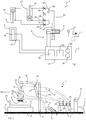
- the assembly device 1 is shown in the form of a pneumatic diagram, whereas in Figure 2 the assembly device 1 is shown in a schematic side view.
- the mounting device 1 serves to vulcanize tire pressure sensors, which are referred to below as tire modules 2, onto the inside of a pneumatic tire for vehicles.
- tire modules 2 are from the prior art, for example from DE 10 2012 007 071 A1 known, and comprises an encapsulated electronic device for measuring and / or monitoring the air pressure in the tire and a hat-shaped holder 3 for receiving the electronic device.
- the hat-shaped holder 3 of the tire module 2 has - as from Figure 3 can be seen - a peripheral edge 4, which is used to attach the tire module 2 to the inside of the pneumatic tire.
- the assembly device 1 serves to vulcanize a supply with an alternating voltage of 230 Vac, which with reference to Figure 1
- An electric box 6 is supplied via a voltage supply line 5, and compressed air up to 8 bar is required, via a Compressed air supply line 7 is fed to a pressure reducer 8, from where the compressed air is provided to a line system 9 (pneumatic system) of the assembly device 1.
- the pressure reducer 8 ensures that a pressure of 8 bar is not exceeded for the line system 9.
- the pressure reducer 8 is fastened together with further components of the assembly device 1, which will be described in more detail below, on a base plate 10 made of, for example, aluminum.
- a stand 11 of the mounting device 1 is also fixed, from which a support arm 12 extends.
- the support arm 12 is pivotally mounted on the stand 11 with a first longitudinal end, whereas a setting head 14 is attached to the longitudinal end facing away from the stand 11 and holds a tire module 2 intended for attachment to the pneumatic tire.
- the setting head 14 can be lowered with the aid of a piston rod 15 of a first pneumatic cylinder 16 in the direction of the base plate 10 in order to press the setting head 14 with a predetermined force onto the inside of a pneumatic tire for fastening a tire module 2, the setting head 14 likewise using the first Pneumatic cylinder 16 can be raised again.
- the support arm 12 is pivotally mounted on the stand 11 with its longitudinal end facing away from the setting head 14, so that the longitudinal end of the support arm 12 having the setting head 14 can be lowered and raised.
- a second pneumatic cylinder 17 is provided, the piston rod 18 of which can pivot the support arm 12.
- the second pneumatic cylinder 17 is attached to the stand 11, an attachment to the support arm 12 alternatively also being conceivable.
- the support arm 12 can be pivoted between a position which raises the setting head 14 and a lower position which holds the support arm 12 essentially transversely to the stand 11.
- a scale 19 is provided for determining and / or checking and / or calibrating the force with which the setting head 14 is pressed onto the inside of a pneumatic tire the base plate 10 is arranged below the setting head 14.
- An industrial scale for example, can be used as scale 19.
- the mounting device 1 comprises, in addition to the scale 19, a centric vice 20, which is arranged on the scale 19 and consequently also below the setting head 14 and enables a reproducible alignment and placement of the pneumatic tire.
- the centering vice 20 is designed as a mechanical centering vice, alternatively the use of a pneumatic centering vice is also conceivable, which is integrated into the line system 9 and can be controlled via valve technology.
- the pressure reducer 8 is arranged upstream of the two pneumatic cylinders 16, 17 and adjusts the system pressure, as already explained above.
- a directional control valve 21 is arranged between the pressure reducer 8 and the two pneumatic cylinders 16, 17 and can be electrically controlled by a user with the aid of the electrical box 6.
- the directional control valve 21 consequently serves to control the two pneumatic cylinders 16, 17 by adopting different switching positions which are predetermined by the electrical box 6.
- a first supply line 22 and a second supply line 23 depart from the directional control valve 21.
- the first feed line 22 divides into a branch line 24 leading to the first pneumatic cylinder 16 and into a branch line 25 leading to the second pneumatic cylinder 17.
- the second feed line 23 likewise divides into a branch line 26 leading to the first pneumatic cylinder 16 and into one of them Second pneumatic cylinder 17 leading branch line 27.
- a throttle valve 28, 29, 30, 31 is arranged in order to reduce the pressure for the fluid flowing to the pneumatic cylinders 16, 17 and the Increase volume.
- a respective feed line 22, 23 is divided into a branch line 24, 26 leading to the first pneumatic cylinder 16 and a branch line 25, 27 leading to the second pneumatic cylinder 17, each in a respective branch line 24, 25, 26, 27 Throttle valve 28, 29, 30, 31 for sequence control of the pneumatic cylinders 16, 17 is arranged.
- the compressed air lines are in Figure 2 indicated by dashed lines and are only intended to illustrate the connection.
- the supply of compressed air from the pressure reducer 8 via the directional valve 21, which is designed as a 5/2-way valve, to the throttle valves 28, 29, 30, 31 is controlled electrically with the aid of the electrical box 6.
- the electrical box 6 has a timer 32 for checking the duration of the fastening process, a reset button 33 for ending the fastening process and a start button 34 for starting the fastening process.
- the electrical box 6 of the assembly device 1 further comprises a temperature controller 35, which serves to regulate the temperature of the setting head 14.
- the setting head 14 has at least one heating element 36 for the integral connection of the tire module 2 to the inside of the pneumatic tire, the heating element 36 preferably being designed as a PTC heating element.
- the latter has at least one temperature sensor 37, which is arranged, for example, in a bore on the longitudinal end of the setting head 14 holding the tire module 2.
- the setting head 14 So that the setting head 14 also presses the tire module 2 evenly during the fastening process onto the inside of the pneumatic tire, the setting head 14 is attached to the support arm 12 by means of a cardanic bearing 38, which in the Figures 2 and 3 is only indicated as an example.
- a cardanic bearing 38 which in the Figures 2 and 3 is only indicated as an example.
- the tire module 2 is first fixed to the setting head 14 for attachment to the pneumatic tire and is detached from the setting head 14 after attachment.
- the setting head 14 of the mounting device 1 has a holding device 39, with which the tire module 2 can be releasably held in a clamping manner on the setting head 14 during fastening.
- the setting head 14 is designed as a hollow cylinder 40, as shown in FIG Figure 3 is indicated by the dashed lines.
- the hat-shaped tire module 2 is inserted into the cavity 41 of the setting head 14 indented that the peripheral edge 4 and the underside of the hat-shaped tire module 2 are arranged on the longitudinal end of the setting head 14 facing away from the first pneumatic cylinder 16.
- the hollow cylinder 40 and its cavity 41 thus form the holding device 39, which holds the tire module 2 releasably in a clamping manner.
- the heating element 36 of the setting head 14 heating the hollow cylinder 40 and thus the peripheral edge 4 of the tire module 2 to the temperature required for the integral connection , so that together with the predetermined pressure of the first pneumatic cylinder 16, with which the tire module 2 is pressed onto the inside of the pneumatic tire, and a predetermined pressing time, at least the peripheral edge 4 is vulcanized onto the inside of the pneumatic tire.
- the pressing time is approximately one minute to establish the integral connection.
- the assembly device 1 described above is operated with the aid of compressed air, the required system pressure, which is supplied to the directional control valve 21, being ensured via a pressure reducer 8.
- the directional control valve 21 is controlled by the electrical box 6, so that the two pneumatic cylinders 16, 17 are acted upon accordingly with compressed air in a time-controlled manner.
- the electrical box 6 also checks whether the heating element 18 on the setting head 14 provides the necessary heating at the longitudinal end of the setting head 14 by the temperature sensor 37 being coupled to the electrical box 6 and being controllable by the latter.
- the assembly device 1 comprises a basic structure made of a stable aluminum plate 10 on which an industrial scale 19, a pivotable support arm 12 with a setting head 14, pneumatic elements (for example pneumatic cylinders 16, 17 and throttle valves 28, 29, 30, 31) and one Elektrobox 6 are attached.
- pneumatic elements for example pneumatic cylinders 16, 17 and throttle valves 28, 29, 30, 31
- one Elektrobox 6 are attached.
- a centric vice 20 is mounted on the industrial scale 19 in order to always position the center of the tire in the same way.
- the scale 19 can be zeroed and the force applied can later be read off on a display of the electrical box 6.
- the force is proportional to the system pressure, which is adjustable via the pressure reducer 8. 2 bar on the pressure reducer corresponds to approx. 6 kg contact pressure and 6 bar approx. 15 kg contact pressure.
- the pressure reducer 8 is shown with its display, whereas in Figure 2 the display shows the pressure reducer.
- a temperature controller 35 (Tempatron PID500), a timer 32 (timer module, for example Panasonic LT4H) and a start button 34 as well as a reset button 33 are combined in the electrical box 6.
- the temperature controller 35 controls a semiconductor relay in order to heat the at least one heating element 36 with 200 W on the setting head 14 to the required temperature. This is achieved and maintained very precisely via a PID controller function without excessive overshoot.
- the setpoint and actual value are displayed at all times.
- the temperature sensor 37 is mounted in a bore at the lowermost end of the setting head 14 in order to measure the temperature on the pressing surface or pressing surface between the tire module 2 and the inside of the pneumatic tire as precisely as possible. Typical values are between 120-150 ° C.
- the system is intrinsically safe and does not heat up to more than 230 ° C even with constant current.
- the timer 32 is not only used for the display, but also controls the pneumatic valve or directional valve 21.
- the start button 34 runs the time and moves the pneumatic cylinders 16, 17 into the lower position.
- the reset button 33 or the expiry of the set time switch the pneumatic valve or directional control valve 21 again so that the setting head 14 is lifted off the pneumatic tire again.
- the pivotable support arm 12 is moved via the second pneumatic cylinder 17 from the open, inclined position into a horizontal position.
- the first pneumatic cylinder 16 then presses the setting head 14 exactly vertically onto the tire surface or inside of the pneumatic tire. Through this Angled application is avoided.
- the setting head 14 is gimbaled to compensate for the curvature and slight bumps in the tire.
- the sequence is controlled by reducing valves or throttle valves 28, 29, 30, 31.
- the inflow to the first pneumatic cylinder 16 with the setting head 14 is reduced significantly more than to the second pneumatic cylinder 17.
- the setting is inverted accordingly.
- the setting head 14 is hollow-drilled with a slight undersize, consequently clamps the tire pressure sensor or the tire module 2 automatically and is chamfered by approximately 4 ° in order to compensate for the deformation of the hat-like tire module 2.
Landscapes
- Engineering & Computer Science (AREA)
- Mechanical Engineering (AREA)
- Tires In General (AREA)
- Heating, Cooling, Or Curing Plastics Or The Like In General (AREA)
- Vehicle Cleaning, Maintenance, Repair, Refitting, And Outriggers (AREA)
- Moulds For Moulding Plastics Or The Like (AREA)
Claims (11)
- Dispositif de montage (1) pour fixer un module de pneumatique en forme de chapeau (2), en particulier un capteur de pression de pneumatique, sur un côté intérieur d'un pneumatique pour véhicules, comportant un montant (11), duquel s'étend un bras de support (12), sachant qu'à l'extrémité longitudinale du bras de support (12) opposée au montant (11) est monté une tête de pose (14) abaissable avec une force prédéfinie, sachant que la tête de pose (14) comporte un dispositif de maintien (39), avec lequel le module de pneumatique en forme de chapeau (2) peut être maintenu de façon amovible sur la tête de pose (14) pendant la fixation en mode serré, et au moins un élément chauffant (36) pour la liaison par conformité de matière du module de pneumatique en forme de chapeau (2) avec la face intérieure du pneumatique,
sachant que le bras de support (12) est logé pouvant pivoter sur le montant (11) à son extrémité longitudinale opposée à la tête de pose (14),
sachant que sur le bras de support (12) est disposé au moins un premier vérin pneumatique (16) constitué levant et descendant avec la force prédéfinie la tête de pose (14), et
sachant que la tête de pose (14) est constituée comme un cylindre creux (40) et le module de pneumatique en forme de chapeau (2) est disposé enfoncé dans l'espace creux (41) de la tête de pose (14) de telle manière que le bord périphérique (4) du module de pneumatique (2) et la face inférieure du module de pneumatique en forme de chapeau (2) sont disposés sur une extrémité longitudinale opposée au premier vérin pneumatique (16) de la tête de pose (14) de telle sorte que lors de la descente de la tête de pose (14) au moins le bord périphérique (4) du module de pneumatique en forme de chapeau (2) est comprimé sur la face intérieure du pneumatique. - Dispositif de montage (1) selon la revendication 1, caractérisé en ce qu'au moins un élément chauffant (36) est constitué comme un élément chauffant à coefficient positif de température (CPT).
- Dispositif de montage (1) selon la revendication 1 ou 2, caractérisé en ce que la tête de pose (14) comporte au moins une sonde de température (37), qui est disposée à l'extrémité longitudinale maintenant le module de pneumatique (2) de la tête de pose (14).
- Dispositif de montage (1) selon l'une quelconque des revendications précédentes, caractérisé en ce que la tête de pose (14) est montée sur le bras de support (12) au moyen d'un montage à Cardan (38).
- Dispositif de montage (1) selon l'une quelconque des revendications précédentes, caractérisé en ce qu'une bascule (19), en particulier une bascule industrielle, est prévue pour contrôler et étalonner la force prédéfinie, qui est disposée en dessous de la tête de pose (14).
- Dispositif de montage (1) selon l'une quelconque des revendications précédentes, caractérisé en ce qu'un centreur (20) constitué pour l'orientation reproductible d'un pneumatique est disposé en dessous de la tête de pose (14).
- Dispositif de montage (1) selon la revendication 1, caractérisé en ce qu'un deuxième vérin pneumatique (17) monté sur le montant (11) ou sur le bras de support (12) pour le pivotement du bras de support (12) est prévu entre une position levant la tête de pose (14) et une position de descente maintenant le bras de support (12) pour l'essentiel transversalement au montant (11).
- Dispositif de montage (1) selon la revendication 7, caractérisé en ce que dans le système de conduites (9) conduisant aux deux vérins pneumatiques (16, 17) est disposé un réducteur de pression (8) servant à régler la pression du système.
- Dispositif de montage (1) selon la revendication 8, caractérisé en ce que dans le système de conduites (9) entre le réducteur de pression (8) et les deux vérins pneumatiques (16, 17) est disposé un distributeur (21), lequel peut être commandé électriquement à l'aide d'un boîtier électrique (6).
- Dispositif de montage (1) selon la revendication 9, caractérisé en ce qu'une première conduite d'alimentation (22) et une deuxième conduite d'alimentation (23) partent du distributeur (21), sachant qu'une conduite d'alimentation respective (22, 23) se divise en une conduite de dérivation (24, 26) conduisant vers le premier vérin pneumatique (16, 17) et une conduite de dérivation (25, 27) conduisant vers le deuxième vérin pneumatique (17), sachant que dans la conduite de dérivation respective (24, 25, 26, 27) est respectivement disposée une soupape d'étranglement (28, 29, 30, 31) pour la commande d'évacuation des vérins pneumatiques (16, 17).
- Dispositif de montage (1) selon la revendication 9 ou 10, caractérisé en ce que le boîtier électrique (6) comprend un régulateur de température (35) pour réguler la température de la tête de pose (14), un compteur de temps (32) pour contrôler la durée de l'opération de fixation, une touche de réinitialisation (33) pour terminer l'opération de fixation et une touche de mise en marche (34) pour mettre en marche l'opération de fixation.
Applications Claiming Priority (2)
| Application Number | Priority Date | Filing Date | Title |
|---|---|---|---|
| DE102014103674.3A DE102014103674A1 (de) | 2014-03-18 | 2014-03-18 | Montagevorrichtung zum Befestigen eines Reifenmoduls |
| PCT/EP2015/052371 WO2015139878A1 (fr) | 2014-03-18 | 2015-02-05 | Dispositif de montage pour fixer un module de pneumatique |
Publications (2)
| Publication Number | Publication Date |
|---|---|
| EP3119598A1 EP3119598A1 (fr) | 2017-01-25 |
| EP3119598B1 true EP3119598B1 (fr) | 2020-01-22 |
Family
ID=52450117
Family Applications (1)
| Application Number | Title | Priority Date | Filing Date |
|---|---|---|---|
| EP15702772.3A Active EP3119598B1 (fr) | 2014-03-18 | 2015-02-05 | Dispositif de montage pour fixer un module de pneumatique |
Country Status (6)
| Country | Link |
|---|---|
| US (1) | US20170021579A1 (fr) |
| EP (1) | EP3119598B1 (fr) |
| KR (1) | KR20160134747A (fr) |
| CN (1) | CN106103064B (fr) |
| DE (1) | DE102014103674A1 (fr) |
| WO (1) | WO2015139878A1 (fr) |
Families Citing this family (7)
| Publication number | Priority date | Publication date | Assignee | Title |
|---|---|---|---|---|
| CN106903919B (zh) * | 2017-04-28 | 2022-10-04 | 漳浦金盛智能科技有限公司 | 折叠椅自动组装机 |
| IT201800011080A1 (it) | 2018-12-13 | 2020-06-13 | Pirelli | Metodo e stazione per applicare un dispositivo di rilevamento ad uno pneumatico |
| FR3113381B1 (fr) * | 2020-08-13 | 2022-07-15 | Michelin & Cie | Installation et Procédé de Préparation et d’Encollage des Dispositifs de Fixation des Organes Electroniques aux Enveloppes des Pneumatiques |
| IT202100032225A1 (it) * | 2021-12-22 | 2023-06-22 | Bridgestone Europe Nv Sa | Metodo di produzione di uno pneumatico provvisto di un dispositivo elettronico |
| IT202300028152A1 (it) * | 2023-12-28 | 2025-06-28 | Pirelli | Processo ed impianto per fissare un inserto funzionale ad uno pneumatico |
| WO2025141357A1 (fr) * | 2023-12-28 | 2025-07-03 | Pirelli Tyre S.P.A. | Procédé et appareil pour associer des inserts fonctionnels à des pneumatiques pour roues de véhicule |
| WO2025196729A1 (fr) * | 2024-03-22 | 2025-09-25 | Bridgestone Europe Nv/Sa | Procédé et système d'application pour fixer un support pour un dispositif électronique à un pneumatique |
Citations (7)
| Publication number | Priority date | Publication date | Assignee | Title |
|---|---|---|---|---|
| US3871106A (en) * | 1972-06-14 | 1975-03-18 | Hofmann Maschf Geb | Methods and apparatuses for dynamic axle angle measurement on motor vehicles |
| US20040262827A1 (en) * | 2003-06-26 | 2004-12-30 | Yevgeny Antonovsky | Air cylinder with high frequency shock absorber and accelerator |
| US20060032563A1 (en) * | 2004-08-13 | 2006-02-16 | Weaver Douglas R | Apparatus and method for attaching an annular transponder unit to tire |
| US20070039458A1 (en) * | 2003-11-07 | 2007-02-22 | Japan Science And Technology Agency | Actuator using fluid cylinder, method of controlling the actuator, and choke valve devices |
| US20090165928A1 (en) * | 2007-12-29 | 2009-07-02 | Schober Bradley D | Tire Patch Applicator |
| US20110095870A1 (en) * | 2009-10-23 | 2011-04-28 | John Michael Fenkanyn | Method for measuring pressure in a tire |
| US20120176762A1 (en) * | 2009-09-30 | 2012-07-12 | Elizabeth L Hotaling | Electronics patch with ultra thin adhesive layer |
Family Cites Families (10)
| Publication number | Priority date | Publication date | Assignee | Title |
|---|---|---|---|---|
| CN2120668U (zh) * | 1992-04-17 | 1992-11-04 | 天津市橡胶制品六厂 | 电补胶加热器 |
| CN100550217C (zh) * | 2002-06-19 | 2009-10-14 | 松下电器产业株式会社 | 柔性ptc发热体及其制造方法 |
| CN100536040C (zh) * | 2002-06-19 | 2009-09-02 | 松下电器产业株式会社 | 柔性ptc发热体及其制造方法 |
| KR101213942B1 (ko) * | 2005-04-26 | 2012-12-18 | 쿠퍼 타이어 앤드 러버 캄파니 | 타이어용 무선주파수 식별장치의 트랜스미터 및 제조방법 |
| DE102008013920A1 (de) * | 2008-03-12 | 2009-09-17 | Snap-On Equipment Gmbh | Vorrichtung und Verfahren zur Temperaturmessung an Fahrzeug-Luftreifen |
| DE102009025794B4 (de) * | 2009-05-13 | 2021-05-12 | Continental Reifen Deutschland Gmbh | Vorrichtung zur Montage von Reifenmodulen auf einen Fahrzeugreifen |
| KR101116871B1 (ko) * | 2009-12-01 | 2012-03-06 | 한국타이어 주식회사 | 타이어 공명음 저감용 흡음체 부착장치 |
| EP2514612A1 (fr) * | 2011-04-21 | 2012-10-24 | Snap-on Equipment Srl a unico socio | Procédé et appareil d'assemblage ou de désassemblage de pneu d'une roue de véhicule |
| US8646404B2 (en) * | 2011-09-26 | 2014-02-11 | Todd E. Hendricks, SR. | Modular system with platformed robot, booth, and fluid delivery system for tire spraying |
| DE102012007071A1 (de) | 2012-04-11 | 2013-10-17 | Huf Hülsbeck & Fürst Gmbh & Co. Kg | Reifenmodul und damit ausgestatteter Reifen |
-
2014
- 2014-03-18 DE DE102014103674.3A patent/DE102014103674A1/de not_active Withdrawn
-
2015
- 2015-02-05 KR KR1020167028482A patent/KR20160134747A/ko not_active Withdrawn
- 2015-02-05 CN CN201580014146.4A patent/CN106103064B/zh active Active
- 2015-02-05 US US15/124,645 patent/US20170021579A1/en not_active Abandoned
- 2015-02-05 EP EP15702772.3A patent/EP3119598B1/fr active Active
- 2015-02-05 WO PCT/EP2015/052371 patent/WO2015139878A1/fr not_active Ceased
Patent Citations (7)
| Publication number | Priority date | Publication date | Assignee | Title |
|---|---|---|---|---|
| US3871106A (en) * | 1972-06-14 | 1975-03-18 | Hofmann Maschf Geb | Methods and apparatuses for dynamic axle angle measurement on motor vehicles |
| US20040262827A1 (en) * | 2003-06-26 | 2004-12-30 | Yevgeny Antonovsky | Air cylinder with high frequency shock absorber and accelerator |
| US20070039458A1 (en) * | 2003-11-07 | 2007-02-22 | Japan Science And Technology Agency | Actuator using fluid cylinder, method of controlling the actuator, and choke valve devices |
| US20060032563A1 (en) * | 2004-08-13 | 2006-02-16 | Weaver Douglas R | Apparatus and method for attaching an annular transponder unit to tire |
| US20090165928A1 (en) * | 2007-12-29 | 2009-07-02 | Schober Bradley D | Tire Patch Applicator |
| US20120176762A1 (en) * | 2009-09-30 | 2012-07-12 | Elizabeth L Hotaling | Electronics patch with ultra thin adhesive layer |
| US20110095870A1 (en) * | 2009-10-23 | 2011-04-28 | John Michael Fenkanyn | Method for measuring pressure in a tire |
Also Published As
| Publication number | Publication date |
|---|---|
| KR20160134747A (ko) | 2016-11-23 |
| EP3119598A1 (fr) | 2017-01-25 |
| US20170021579A1 (en) | 2017-01-26 |
| WO2015139878A1 (fr) | 2015-09-24 |
| CN106103064A (zh) | 2016-11-09 |
| CN106103064B (zh) | 2019-08-06 |
| DE102014103674A1 (de) | 2015-09-24 |
Similar Documents
| Publication | Publication Date | Title |
|---|---|---|
| EP3119598B1 (fr) | Dispositif de montage pour fixer un module de pneumatique | |
| DE4101304C2 (de) | Verfahren und Aufpumpeinrichtung zum Aufpumpen einer Rad/Reifen-Einheit | |
| EP2894006B1 (fr) | Dispositif de serrage, de maintien et de positionnement d'une pièce | |
| DE202013100632U1 (de) | Vakuumspannvorrichtung | |
| DE2659952C3 (de) | Einrichtung zum Besohlen von Reifen | |
| DE102010026618B4 (de) | Verfahren zum Erfassen der Temperatur von Siegelwerkzeugen | |
| DE102008028238A1 (de) | Spannvorrichtung | |
| DE102009025794A1 (de) | Vorrichtung zur Montage von Reifenmodulen auf einen Fahrzeugreifen | |
| DE19956506A1 (de) | Vorrichtung zum Tiefziehen von becherförmigen Körpern | |
| EP2219818B1 (fr) | Machine de traitement multiaxe et procédé de commande à élasticité | |
| AT518705A2 (de) | Kopiereinrichtung und eine diese enthaltende Fräsvorrichtung zur Bearbeitung einer an einer Platte angebrachten Kante | |
| AT520556B1 (de) | Modular erweiterbare Vakuumpresse | |
| DE19615058C2 (de) | Spannvorrichtung und Schablonen für Schablonen- oder Siebdruck | |
| DD253179A5 (de) | Klebepresse zur ankleben von schuhsohlen an aufgeleisteten oberschuhen | |
| EP3953164A1 (fr) | Procédé et dispositif de mesure servant à mesurer ou à étalonner des ustensiles de presses | |
| DE202024100615U1 (de) | Vorrichtung zur Herstellung von dreidimensionalen Siebdruckwerkstücken | |
| WO2003097460A1 (fr) | Dispositif permettant de sceller des recipients en forme de coupes ou de pots | |
| DE1673572A1 (de) | Druckmittelbetaetigter Regler | |
| DE102024139665B3 (de) | Verfahren und Vorrichtung zum Beziehen 3D-gedruckter orthopädischer Schuheinlagen | |
| DE19904808C1 (de) | Verfahren und Vorrichtung zur Bestimmung von Adhäsionseffekten an Produktionswerkzeugen | |
| DE3214043C2 (fr) | ||
| DE371207C (de) | Vulkanisiervorrichtung | |
| DE202024100613U1 (de) | Vorrichtung zur Herstellung von dreidimensionalen Siebdruckwerkstücken | |
| DE102015205025A1 (de) | Verfahren zum Erzeugen der optimalen Anpresskraft einer Rakel an ein Drucksieb und eine hierfür geeignete Rotationssiebdruckmaschine | |
| WO2025168628A1 (fr) | Appareil de production de pièces sérigraphiées en trois dimensions |
Legal Events
| Date | Code | Title | Description |
|---|---|---|---|
| STAA | Information on the status of an ep patent application or granted ep patent |
Free format text: STATUS: THE INTERNATIONAL PUBLICATION HAS BEEN MADE |
|
| PUAI | Public reference made under article 153(3) epc to a published international application that has entered the european phase |
Free format text: ORIGINAL CODE: 0009012 |
|
| STAA | Information on the status of an ep patent application or granted ep patent |
Free format text: STATUS: REQUEST FOR EXAMINATION WAS MADE |
|
| 17P | Request for examination filed |
Effective date: 20161018 |
|
| AK | Designated contracting states |
Kind code of ref document: A1 Designated state(s): AL AT BE BG CH CY CZ DE DK EE ES FI FR GB GR HR HU IE IS IT LI LT LU LV MC MK MT NL NO PL PT RO RS SE SI SK SM TR |
|
| AX | Request for extension of the european patent |
Extension state: BA ME |
|
| DAX | Request for extension of the european patent (deleted) | ||
| STAA | Information on the status of an ep patent application or granted ep patent |
Free format text: STATUS: EXAMINATION IS IN PROGRESS |
|
| 17Q | First examination report despatched |
Effective date: 20190219 |
|
| RAP1 | Party data changed (applicant data changed or rights of an application transferred) |
Owner name: HUF BAOLONG ELECTRONICS BRETTEN GMBH |
|
| GRAP | Despatch of communication of intention to grant a patent |
Free format text: ORIGINAL CODE: EPIDOSNIGR1 |
|
| STAA | Information on the status of an ep patent application or granted ep patent |
Free format text: STATUS: GRANT OF PATENT IS INTENDED |
|
| INTG | Intention to grant announced |
Effective date: 20191021 |
|
| GRAS | Grant fee paid |
Free format text: ORIGINAL CODE: EPIDOSNIGR3 |
|
| GRAA | (expected) grant |
Free format text: ORIGINAL CODE: 0009210 |
|
| STAA | Information on the status of an ep patent application or granted ep patent |
Free format text: STATUS: THE PATENT HAS BEEN GRANTED |
|
| AK | Designated contracting states |
Kind code of ref document: B1 Designated state(s): AL AT BE BG CH CY CZ DE DK EE ES FI FR GB GR HR HU IE IS IT LI LT LU LV MC MK MT NL NO PL PT RO RS SE SI SK SM TR |
|
| REG | Reference to a national code |
Ref country code: GB Ref legal event code: FG4D Free format text: NOT ENGLISH |
|
| REG | Reference to a national code |
Ref country code: CH Ref legal event code: EP |
|
| REG | Reference to a national code |
Ref country code: AT Ref legal event code: REF Ref document number: 1226652 Country of ref document: AT Kind code of ref document: T Effective date: 20200215 |
|
| REG | Reference to a national code |
Ref country code: IE Ref legal event code: FG4D Free format text: LANGUAGE OF EP DOCUMENT: GERMAN |
|
| REG | Reference to a national code |
Ref country code: DE Ref legal event code: R096 Ref document number: 502015011579 Country of ref document: DE |
|
| REG | Reference to a national code |
Ref country code: NL Ref legal event code: MP Effective date: 20200122 |
|
| REG | Reference to a national code |
Ref country code: LT Ref legal event code: MG4D |
|
| PG25 | Lapsed in a contracting state [announced via postgrant information from national office to epo] |
Ref country code: NL Free format text: LAPSE BECAUSE OF FAILURE TO SUBMIT A TRANSLATION OF THE DESCRIPTION OR TO PAY THE FEE WITHIN THE PRESCRIBED TIME-LIMIT Effective date: 20200122 Ref country code: NO Free format text: LAPSE BECAUSE OF FAILURE TO SUBMIT A TRANSLATION OF THE DESCRIPTION OR TO PAY THE FEE WITHIN THE PRESCRIBED TIME-LIMIT Effective date: 20200422 Ref country code: PT Free format text: LAPSE BECAUSE OF FAILURE TO SUBMIT A TRANSLATION OF THE DESCRIPTION OR TO PAY THE FEE WITHIN THE PRESCRIBED TIME-LIMIT Effective date: 20200614 Ref country code: FI Free format text: LAPSE BECAUSE OF FAILURE TO SUBMIT A TRANSLATION OF THE DESCRIPTION OR TO PAY THE FEE WITHIN THE PRESCRIBED TIME-LIMIT Effective date: 20200122 Ref country code: RS Free format text: LAPSE BECAUSE OF FAILURE TO SUBMIT A TRANSLATION OF THE DESCRIPTION OR TO PAY THE FEE WITHIN THE PRESCRIBED TIME-LIMIT Effective date: 20200122 |
|
| PG25 | Lapsed in a contracting state [announced via postgrant information from national office to epo] |
Ref country code: IS Free format text: LAPSE BECAUSE OF FAILURE TO SUBMIT A TRANSLATION OF THE DESCRIPTION OR TO PAY THE FEE WITHIN THE PRESCRIBED TIME-LIMIT Effective date: 20200522 Ref country code: HR Free format text: LAPSE BECAUSE OF FAILURE TO SUBMIT A TRANSLATION OF THE DESCRIPTION OR TO PAY THE FEE WITHIN THE PRESCRIBED TIME-LIMIT Effective date: 20200122 Ref country code: SE Free format text: LAPSE BECAUSE OF FAILURE TO SUBMIT A TRANSLATION OF THE DESCRIPTION OR TO PAY THE FEE WITHIN THE PRESCRIBED TIME-LIMIT Effective date: 20200122 Ref country code: LV Free format text: LAPSE BECAUSE OF FAILURE TO SUBMIT A TRANSLATION OF THE DESCRIPTION OR TO PAY THE FEE WITHIN THE PRESCRIBED TIME-LIMIT Effective date: 20200122 Ref country code: GR Free format text: LAPSE BECAUSE OF FAILURE TO SUBMIT A TRANSLATION OF THE DESCRIPTION OR TO PAY THE FEE WITHIN THE PRESCRIBED TIME-LIMIT Effective date: 20200423 Ref country code: BG Free format text: LAPSE BECAUSE OF FAILURE TO SUBMIT A TRANSLATION OF THE DESCRIPTION OR TO PAY THE FEE WITHIN THE PRESCRIBED TIME-LIMIT Effective date: 20200422 |
|
| REG | Reference to a national code |
Ref country code: CH Ref legal event code: PL |
|
| REG | Reference to a national code |
Ref country code: DE Ref legal event code: R097 Ref document number: 502015011579 Country of ref document: DE |
|
| REG | Reference to a national code |
Ref country code: BE Ref legal event code: MM Effective date: 20200229 |
|
| PG25 | Lapsed in a contracting state [announced via postgrant information from national office to epo] |
Ref country code: LT Free format text: LAPSE BECAUSE OF FAILURE TO SUBMIT A TRANSLATION OF THE DESCRIPTION OR TO PAY THE FEE WITHIN THE PRESCRIBED TIME-LIMIT Effective date: 20200122 Ref country code: DK Free format text: LAPSE BECAUSE OF FAILURE TO SUBMIT A TRANSLATION OF THE DESCRIPTION OR TO PAY THE FEE WITHIN THE PRESCRIBED TIME-LIMIT Effective date: 20200122 Ref country code: ES Free format text: LAPSE BECAUSE OF FAILURE TO SUBMIT A TRANSLATION OF THE DESCRIPTION OR TO PAY THE FEE WITHIN THE PRESCRIBED TIME-LIMIT Effective date: 20200122 Ref country code: SM Free format text: LAPSE BECAUSE OF FAILURE TO SUBMIT A TRANSLATION OF THE DESCRIPTION OR TO PAY THE FEE WITHIN THE PRESCRIBED TIME-LIMIT Effective date: 20200122 Ref country code: EE Free format text: LAPSE BECAUSE OF FAILURE TO SUBMIT A TRANSLATION OF THE DESCRIPTION OR TO PAY THE FEE WITHIN THE PRESCRIBED TIME-LIMIT Effective date: 20200122 Ref country code: RO Free format text: LAPSE BECAUSE OF FAILURE TO SUBMIT A TRANSLATION OF THE DESCRIPTION OR TO PAY THE FEE WITHIN THE PRESCRIBED TIME-LIMIT Effective date: 20200122 Ref country code: CZ Free format text: LAPSE BECAUSE OF FAILURE TO SUBMIT A TRANSLATION OF THE DESCRIPTION OR TO PAY THE FEE WITHIN THE PRESCRIBED TIME-LIMIT Effective date: 20200122 Ref country code: SK Free format text: LAPSE BECAUSE OF FAILURE TO SUBMIT A TRANSLATION OF THE DESCRIPTION OR TO PAY THE FEE WITHIN THE PRESCRIBED TIME-LIMIT Effective date: 20200122 Ref country code: LU Free format text: LAPSE BECAUSE OF NON-PAYMENT OF DUE FEES Effective date: 20200205 Ref country code: MC Free format text: LAPSE BECAUSE OF FAILURE TO SUBMIT A TRANSLATION OF THE DESCRIPTION OR TO PAY THE FEE WITHIN THE PRESCRIBED TIME-LIMIT Effective date: 20200122 |
|
| PLBE | No opposition filed within time limit |
Free format text: ORIGINAL CODE: 0009261 |
|
| STAA | Information on the status of an ep patent application or granted ep patent |
Free format text: STATUS: NO OPPOSITION FILED WITHIN TIME LIMIT |
|
| PG25 | Lapsed in a contracting state [announced via postgrant information from national office to epo] |
Ref country code: LI Free format text: LAPSE BECAUSE OF NON-PAYMENT OF DUE FEES Effective date: 20200229 Ref country code: CH Free format text: LAPSE BECAUSE OF NON-PAYMENT OF DUE FEES Effective date: 20200229 |
|
| 26N | No opposition filed |
Effective date: 20201023 |
|
| PG25 | Lapsed in a contracting state [announced via postgrant information from national office to epo] |
Ref country code: IT Free format text: LAPSE BECAUSE OF FAILURE TO SUBMIT A TRANSLATION OF THE DESCRIPTION OR TO PAY THE FEE WITHIN THE PRESCRIBED TIME-LIMIT Effective date: 20200122 Ref country code: IE Free format text: LAPSE BECAUSE OF NON-PAYMENT OF DUE FEES Effective date: 20200205 |
|
| PG25 | Lapsed in a contracting state [announced via postgrant information from national office to epo] |
Ref country code: BE Free format text: LAPSE BECAUSE OF NON-PAYMENT OF DUE FEES Effective date: 20200229 Ref country code: PL Free format text: LAPSE BECAUSE OF FAILURE TO SUBMIT A TRANSLATION OF THE DESCRIPTION OR TO PAY THE FEE WITHIN THE PRESCRIBED TIME-LIMIT Effective date: 20200122 Ref country code: SI Free format text: LAPSE BECAUSE OF FAILURE TO SUBMIT A TRANSLATION OF THE DESCRIPTION OR TO PAY THE FEE WITHIN THE PRESCRIBED TIME-LIMIT Effective date: 20200122 |
|
| REG | Reference to a national code |
Ref country code: AT Ref legal event code: MM01 Ref document number: 1226652 Country of ref document: AT Kind code of ref document: T Effective date: 20200205 |
|
| PG25 | Lapsed in a contracting state [announced via postgrant information from national office to epo] |
Ref country code: AT Free format text: LAPSE BECAUSE OF NON-PAYMENT OF DUE FEES Effective date: 20200205 |
|
| PG25 | Lapsed in a contracting state [announced via postgrant information from national office to epo] |
Ref country code: TR Free format text: LAPSE BECAUSE OF FAILURE TO SUBMIT A TRANSLATION OF THE DESCRIPTION OR TO PAY THE FEE WITHIN THE PRESCRIBED TIME-LIMIT Effective date: 20200122 Ref country code: MT Free format text: LAPSE BECAUSE OF FAILURE TO SUBMIT A TRANSLATION OF THE DESCRIPTION OR TO PAY THE FEE WITHIN THE PRESCRIBED TIME-LIMIT Effective date: 20200122 Ref country code: CY Free format text: LAPSE BECAUSE OF FAILURE TO SUBMIT A TRANSLATION OF THE DESCRIPTION OR TO PAY THE FEE WITHIN THE PRESCRIBED TIME-LIMIT Effective date: 20200122 |
|
| PG25 | Lapsed in a contracting state [announced via postgrant information from national office to epo] |
Ref country code: MK Free format text: LAPSE BECAUSE OF FAILURE TO SUBMIT A TRANSLATION OF THE DESCRIPTION OR TO PAY THE FEE WITHIN THE PRESCRIBED TIME-LIMIT Effective date: 20200122 Ref country code: AL Free format text: LAPSE BECAUSE OF FAILURE TO SUBMIT A TRANSLATION OF THE DESCRIPTION OR TO PAY THE FEE WITHIN THE PRESCRIBED TIME-LIMIT Effective date: 20200122 |
|
| PGFP | Annual fee paid to national office [announced via postgrant information from national office to epo] |
Ref country code: GB Payment date: 20260219 Year of fee payment: 12 |
|
| REG | Reference to a national code |
Ref country code: DE Ref legal event code: R082 Ref document number: 502015011579 Country of ref document: DE Representative=s name: TWELMEIER MOMMER & PARTNER PATENT- UND RECHTSA, DE |
|
| PGFP | Annual fee paid to national office [announced via postgrant information from national office to epo] |
Ref country code: DE Payment date: 20260228 Year of fee payment: 12 |
|
| PGFP | Annual fee paid to national office [announced via postgrant information from national office to epo] |
Ref country code: FR Payment date: 20260223 Year of fee payment: 12 |