EP3120004B1 - Ensemble d'actionnement et procédé de fonctionnement d'un actionneur - Google Patents
Ensemble d'actionnement et procédé de fonctionnement d'un actionneur Download PDFInfo
- Publication number
- EP3120004B1 EP3120004B1 EP15802430.7A EP15802430A EP3120004B1 EP 3120004 B1 EP3120004 B1 EP 3120004B1 EP 15802430 A EP15802430 A EP 15802430A EP 3120004 B1 EP3120004 B1 EP 3120004B1
- Authority
- EP
- European Patent Office
- Prior art keywords
- centrifugal pump
- pressure
- stage
- control valve
- pump
- Prior art date
- Legal status (The legal status is an assumption and is not a legal conclusion. Google has not performed a legal analysis and makes no representation as to the accuracy of the status listed.)
- Active
Links
Images



Classifications
-
- F—MECHANICAL ENGINEERING; LIGHTING; HEATING; WEAPONS; BLASTING
- F04—POSITIVE - DISPLACEMENT MACHINES FOR LIQUIDS; PUMPS FOR LIQUIDS OR ELASTIC FLUIDS
- F04D—NON-POSITIVE-DISPLACEMENT PUMPS
- F04D15/00—Control, e.g. regulation, of pumps, pumping installations or systems
- F04D15/0005—Control, e.g. regulation, of pumps, pumping installations or systems by using valves
-
- B—PERFORMING OPERATIONS; TRANSPORTING
- B64—AIRCRAFT; AVIATION; COSMONAUTICS
- B64D—EQUIPMENT FOR FITTING IN OR TO AIRCRAFT; FLIGHT SUITS; PARACHUTES; ARRANGEMENT OR MOUNTING OF POWER PLANTS OR PROPULSION TRANSMISSIONS IN AIRCRAFT
- B64D37/00—Arrangements in connection with fuel supply for power plant
- B64D37/005—Accessories not provided for in the groups B64D37/02 - B64D37/28
-
- F—MECHANICAL ENGINEERING; LIGHTING; HEATING; WEAPONS; BLASTING
- F02—COMBUSTION ENGINES; HOT-GAS OR COMBUSTION-PRODUCT ENGINE PLANTS
- F02C—GAS-TURBINE PLANTS; AIR INTAKES FOR JET-PROPULSION PLANTS; CONTROLLING FUEL SUPPLY IN AIR-BREATHING JET-PROPULSION PLANTS
- F02C7/00—Features, components parts, details or accessories, not provided for in, or of interest apart form groups F02C1/00 - F02C6/00; Air intakes for jet-propulsion plants
- F02C7/22—Fuel supply systems
- F02C7/236—Fuel delivery systems comprising two or more pumps
-
- F—MECHANICAL ENGINEERING; LIGHTING; HEATING; WEAPONS; BLASTING
- F04—POSITIVE - DISPLACEMENT MACHINES FOR LIQUIDS; PUMPS FOR LIQUIDS OR ELASTIC FLUIDS
- F04C—ROTARY-PISTON, OR OSCILLATING-PISTON, POSITIVE-DISPLACEMENT MACHINES FOR LIQUIDS; ROTARY-PISTON, OR OSCILLATING-PISTON, POSITIVE-DISPLACEMENT PUMPS
- F04C14/00—Control of, monitoring of, or safety arrangements for, machines, pumps or pumping installations
- F04C14/02—Control of, monitoring of, or safety arrangements for, machines, pumps or pumping installations specially adapted for several machines or pumps connected in series or in parallel
-
- F—MECHANICAL ENGINEERING; LIGHTING; HEATING; WEAPONS; BLASTING
- F04—POSITIVE - DISPLACEMENT MACHINES FOR LIQUIDS; PUMPS FOR LIQUIDS OR ELASTIC FLUIDS
- F04C—ROTARY-PISTON, OR OSCILLATING-PISTON, POSITIVE-DISPLACEMENT MACHINES FOR LIQUIDS; ROTARY-PISTON, OR OSCILLATING-PISTON, POSITIVE-DISPLACEMENT PUMPS
- F04C2/00—Rotary-piston machines or pumps
- F04C2/08—Rotary-piston machines or pumps of intermeshing-engagement type, i.e. with engagement of co-operating members similar to that of toothed gearing
- F04C2/082—Details specially related to intermeshing engagement type machines or pumps
- F04C2/084—Toothed wheels
-
- F—MECHANICAL ENGINEERING; LIGHTING; HEATING; WEAPONS; BLASTING
- F04—POSITIVE - DISPLACEMENT MACHINES FOR LIQUIDS; PUMPS FOR LIQUIDS OR ELASTIC FLUIDS
- F04D—NON-POSITIVE-DISPLACEMENT PUMPS
- F04D1/00—Radial-flow pumps, e.g. centrifugal pumps; Helico-centrifugal pumps
- F04D1/06—Multi-stage pumps
-
- F—MECHANICAL ENGINEERING; LIGHTING; HEATING; WEAPONS; BLASTING
- F04—POSITIVE - DISPLACEMENT MACHINES FOR LIQUIDS; PUMPS FOR LIQUIDS OR ELASTIC FLUIDS
- F04C—ROTARY-PISTON, OR OSCILLATING-PISTON, POSITIVE-DISPLACEMENT MACHINES FOR LIQUIDS; ROTARY-PISTON, OR OSCILLATING-PISTON, POSITIVE-DISPLACEMENT PUMPS
- F04C2270/00—Control; Monitoring or safety arrangements
- F04C2270/18—Pressure
- F04C2270/185—Controlled or regulated
-
- F—MECHANICAL ENGINEERING; LIGHTING; HEATING; WEAPONS; BLASTING
- F05—INDEXING SCHEMES RELATING TO ENGINES OR PUMPS IN VARIOUS SUBCLASSES OF CLASSES F01-F04
- F05D—INDEXING SCHEME FOR ASPECTS RELATING TO NON-POSITIVE-DISPLACEMENT MACHINES OR ENGINES, GAS-TURBINES OR JET-PROPULSION PLANTS
- F05D2260/00—Function
- F05D2260/70—Adjusting of angle of incidence or attack of rotating blades
- F05D2260/76—Adjusting of angle of incidence or attack of rotating blades the adjusting mechanism using auxiliary power sources
Definitions
- actuation loops are typically supplied from one or more regulated pressure sources and referenced to the low pressure stage of the fuel pump, commonly a centrifugal stage.
- discharge pressure from the pump is regulated or allowed to leak through a valve, or pressure regulator. This leakage is an inefficiency in the fuel system.
- WO 2013/025818 A1 and US 2010/0263634 A1 relate to an actuation assembly comprising at least two centrifugal pumps connected in series, a control valve and an associated actuator according to the preamble of claims 1 and 7.
- the invention relates to an actuation assembly as defined in claim 1 and a method as defined in claim 1 and a method as defined in claim 7.
- the actuation assembly (and the associated method) includes a multistage centrifugal pump and a first control valve.
- the control valve receives a first pressure from one of the centrifugal pump stages and communicates the first pressure for optimally operating an associated first actuator.
- the actuation assembly further includes a second control valve that receives a second pressure from a different centrifugal pump stage and communicates the second pressure for optimally operating an associated second actuator.
- return passages from each control valve return to the same stage of the multistage centrifugal pump.
- the first control valve receives a first pressure from one of the centrifugal pump stages downstream of a first centrifugal pump stage.
- a return passage from the first control valve communicates with the multistage centrifugal pump upstream of the one centrifugal pump stage, particularly with the multistage centrifugal pump upstream of the one centrifugal pump stage.
- the return passage from the first control valve communicates with an inlet of the one centrifugal pump stage, and in another arrangement the first control valve communicates with an inlet of a centrifugal pump stage different than the one centrifugal pump stage.
- the actuation assembly can include a positive displacement pump downstream of the multistage centrifugal pump.
- the actuation assembly further includes a selector valve between the one stage of the multistage centrifugal pump and the first control valve through which pressure is alternately supplied to the first control valve from the one stage and the positive displacement pump.
- the selector valve may be pressure activated to initially forward pressure to the first control valve from the positive displacement pump and then switch to forward pressure from the one stage once the outlet pressure from the centrifugal pump has reached a certain level.
- a primary benefit is the reduction of inefficiencies in engine actuation loops.
- Another advantage relates to the elimination of pressure regulators and the associated leakage of flow therepast associated with conventional systems.
- Still another benefit is the ability to establish multiple fixed ratio pressure differentials for various actuator needs.
- This disclosure uses a multi-stage centrifugal pump solely, or in conjunction with a positive displacement pump, as an engine main fuel pump.
- a multi-stage centrifugal pump uses fixed ratio pressure levels (created between the different pump stages where each stage adds additional energy and pressure to the pumped fluid) and can be used directly by the actuators. This improves the efficiency of the fuel system. Depending on the number of pumping stages, potentially more pressure levels are available for actuation thus allowing for better optimization of the actuators.
- centrifugal stages allow for design and optimization of multiple fixed ratio pressure levels. For instance, if there are three centrifugal stages, then there will be three fixed ratio pressures. Typically, the first stage is the reference or drain pressure for the actuators, thereby leaving the remaining stage or stages as supply pressure levels. The ability to have multiple pressure levels allows for additional optimization of the actuation loops without the need for additional pressure regulators. Flow is only drawn from the centrifugal stages when needed therefore improving the efficiency of the system. Additionally, the fixed ratio of pressure allows for conventional control gains.
- the pump will need to be motor driven.
- a positive displacement pump in conjunction with the centrifugal stages allows the system to develop pressure at the low speeds (provided primarily by the positive displacement pump) which can be used to supply the actuation loops.
- a shuttle type valve for example, can be used to transition the system from the positive displacement discharge pressure to the appropriate centrifugal stage discharge pressure.
- FIG. 1 shown in Figure 1 is an engine main fuel pump 100 that includes a centrifugal stage pump 102 and a positive displacement pump such as gear pump 104.
- Fuel is inlet from passage or line 106 to the centrifugal stage pump 102, pressurized by the centrifugal stage pump, and outlet via passage 108 where it is introduced into the inlet of the gear pump 104.
- the gear pump 104 further pressurizes the fluid (fuel) where it is provided to the engine (not shown) via passage 110.
- a passage 120 branching from the passage 110 is a passage 120 that leads to one or more pressure regulators (two of which are shown as pressure regulator 122A and pressure regulator 122B) for delivery of fuel at reduced pressure levels for control valves 124A, 124B, respectively, via passages 126A, 126B.
- the individual pressure regulators 122A, 122B can deliver the pressurized fuel at the same or different pressures to the respective control valves 124A, 124B.
- Each control valve 124A, 124B communicates via a respective passage 130A, 130B with a respective actuator 128A, 128B. In this manner, fuel at a desired pressure level is delivered to the actuators 128A, 128B.
- discharge pressure from the pump leaks through the valve or the pressure regulator.
- This leakage flow is returned from the pressure regulators 122A, 122B through passages 140A, 140B, and from the valves 124A, 124B through passages 142A, 142B to passage 108 where the flow combines with flow from the centrifugal pump 102 that is introduced into the gear pump 104.
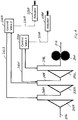
- the new arrangement of Figure 2 advantageously uses a multi-stage centrifugal pump 202, either alone or with the gear pump 204, in a manner that provides multiple fixed ratio pressure levels.
- the multi-stage centrifugal pump 202 includes a first stage 202A, a second stage 202B, and a third stage 202C arranged in series to incrementally increase the pressure from the first stage to the second stage, and likewise from the second stage to the third stage.
- the first stage 202A can be used as the reference pressure, i.e., the return flow from control valves 224A and 224B through passages 242A, 242B, respectively, is directed to the passage 208A disposed between the first and second stages of the multistage centrifugal pump.
- Inlet pressure to the control valve 224A is taken from passage 208C downstream of the third stage 202C of the centrifugal pump, while inlet pressure to control valve 224B is taken from passage 208B downstream of the second stage 202B of the centrifugal pump.
- a greater pressure is provided to the first control valve 224A than to the second control valve 224B in the arrangement of Figure 2 .
- the pressure ratios associated with the embodiment of Figure 2 are related to the speed of the pump (i.e., the pressure from the particular centrifugal pump stage is dependent on the rotational speed of the centrifugal pump) and oftentimes the loads on the actuators are also speed dependent.
- a two position selector valve or shuttle valve 250 is interposed between the third stage 202C of the centrifugal pump/gear pump 204 and the first control valve 224A.
- pressure required for the first control valve 224A and the associated actuator 228A is provided from downstream of the gear pump 204, and once the centrifugal pump speed increases (and thus the outlet pressure of the third stage 202C of the centrifugal pump), selector valve 250 moves from the position shown in Figure 3 to a position where pressure from the outlet of the third stage of the centrifugal pump is supplied to the control valve 224A (and to the associated actuator 228A) through the selector valve 250.
- FIG. 4 Another modification is shown in Figures 4 and 5 .
- the pressure supplied to the control valve 224A comes from the outlet of the third stage 202C of the centrifugal pump.
- the reference pressure for the first control valve 224A is associated with the second stage 202B of the centrifugal pump (and not with the first stage 202A of the centrifugal pump as in the embodiments of Figures 2-3 ).
- Figure 5 further illustrates the same arrangement of Figure 4 without use of a positive displacement pump, such as the gear pump 204 of Figure 4 . In all other respects, the system of Figure 5 is the same.
Landscapes
- Engineering & Computer Science (AREA)
- Mechanical Engineering (AREA)
- General Engineering & Computer Science (AREA)
- Chemical & Material Sciences (AREA)
- Combustion & Propulsion (AREA)
- Aviation & Aerospace Engineering (AREA)
- Structures Of Non-Positive Displacement Pumps (AREA)
Claims (13)
- Ensemble d'actionnement comprenant :une pompe centrifuge à plusieurs étages (202) ; etune première valve de commande (224A) qui reçoit une première pression de l'un des étages de pompe centrifuge (202C) et communique la première pression pour actionner de manière optimale un premier actionneur (228A) associé, caractérisé par une seconde valve de commande (224B) qui reçoit une seconde pression d'un étage de pompe centrifuge différent (202B) et communique la seconde pression pour actionner de manière optimale un second actionneur (228B) associé.
- Ensemble d'actionnement selon la revendication 1, dans lequel les passages de retour (242A, 242B) de chaque valve de commande (224A, 224B) reviennent au même étage (202B) de la pompe centrifuge à plusieurs étages (202).
- Ensemble d'actionnement selon la revendication 1, dans lequel la première valve de commande (224A) reçoit la première pression de l'un des étages de pompe centrifuge (202C) en aval d'un premier étage de pompe centrifuge (202A).
- Ensemble d'actionnement selon la revendication 1, dans lequel un passage de retour (242A) de la première valve de commande (224A) communique avec la pompe centrifuge à plusieurs étages (20) en amont d'un étage de pompe centrifuge (202C) .
- Ensemble d'actionnement selon la revendication 4, dans lequel le passage de retour (242A, 242A') de la première valve de commande (224A) communique avec une entrée de l'un parmi (i) le premier étage de pompe centrifuge (202C), ou (ii) un étage de pompe centrifuge (202B) différent du premier étage de pompe centrifuge.
- Ensemble d'actionnement selon la revendication 1, comprenant en outre une pompe volumétrique (204) en aval de la pompe centrifuge à plusieurs étages (202) ;
l'ensemble comprenant une valve de sélecteur (250) entre le premier étage (202C) de la pompe centrifuge à plusieurs étages (202) et la première valve de commande (224A) à travers laquelle la pression est amenée de manière alternée à la première valve de commande depuis le premier étage et la pompe volumétrique,
dans lequel, en outre, la valve de sélecteur est activée par pression pour diriger initialement la pression vers la première valve de commande (224A) depuis la pompe volumétrique et commuter ensuite pour envoyer la pression à partir du premier étage une fois que la pression de sortie de la pompe centrifuge a atteint un certain niveau. - Procédé de fonctionnement d'un actionneur comprenant les étapes suivantes :prévoir une pompe centrifuge à plusieurs étages (202) ; etdiriger une première pression d'un étage (202C) de la pompe centrifuge à plusieurs étages vers une première valve de commande (224A) pour faire fonctionner de manière optimale un premier actionneur (228A) associé, associé avec la première valve de commande,caractérisé par l'étape pour prévoir une seconde valve de commande (224B) qui reçoit une seconde pression d'un étage de pompe centrifuge différent (202B) ; et communiquer la seconde pression pour faire fonctionner de manière optimale un second actionneur (228B) associé.
- Procédé selon la revendication 7, comprenant en outre l'étape pour prévoir des passages de retour (242A, 242B) de chaque valve de commande (224A, 224B) au même étage (202B) de la pompe centrifuge à plusieurs étages (202).
- Procédé selon la revendication 7, comprenant en outre l'étape pour diriger la première pression de l'un des étages de pompe centrifuge (202C) en aval d'un premier étage de pompe centrifuge (202A) vers la première valve de commande.
- Procédé selon la revendication 7, comprenant en outre l'étape pour prévoir un passage de retour (242A, 242A') de la première valve de commande (224A) qui communique avec la pompe centrifuge à plusieurs étages (202) en amont du premier étage de pompe centrifuge (202C), et raccorder le passage de retour de la première valve de commande avec une entrée (i) du premier étage de pompe centrifuge ou (ii) d'un étage de pompe centrifuge (202B) différent du premier étage de pompe centrifuge.
- Procédé selon la revendication 7, comprenant en outre l'étape pour fournir une pompe volumétrique (204) en aval de la pompe centrifuge à plusieurs étages (202).
- Procédé selon la revendication 11, comprenant en outre l'étape pour prévoir une valve de sélecteur (250) entre le premier étage (202C) de la pompe centrifuge à plusieurs étages (202) et la première valve de commande (224A) à travers laquelle la pression est fournie de manière alternée à la première valve de commande depuis le premier étage et la pompe volumétrique (204).
- Procédé selon la revendication 12, dans laquelle la valve de sélecteur (250) est activée par pression et envoyer initialement la pression vers la première valve de commande (224A) depuis la pompe volumétrique (204) et ensuite commuter pour envoyer la pression à partir du premier étage (202C) une fois que la pression de sortie de la pompe centrifuge (202) a atteint un certain niveau.
Applications Claiming Priority (2)
| Application Number | Priority Date | Filing Date | Title |
|---|---|---|---|
| US201461954484P | 2014-03-17 | 2014-03-17 | |
| PCT/US2015/020897 WO2015187230A2 (fr) | 2014-03-17 | 2015-03-17 | Procédé d'actionnement et rendement |
Publications (3)
| Publication Number | Publication Date |
|---|---|
| EP3120004A2 EP3120004A2 (fr) | 2017-01-25 |
| EP3120004A4 EP3120004A4 (fr) | 2017-12-13 |
| EP3120004B1 true EP3120004B1 (fr) | 2019-08-07 |
Family
ID=54767540
Family Applications (1)
| Application Number | Title | Priority Date | Filing Date |
|---|---|---|---|
| EP15802430.7A Active EP3120004B1 (fr) | 2014-03-17 | 2015-03-17 | Ensemble d'actionnement et procédé de fonctionnement d'un actionneur |
Country Status (4)
| Country | Link |
|---|---|
| US (1) | US10247190B2 (fr) |
| EP (1) | EP3120004B1 (fr) |
| CA (1) | CA2943101C (fr) |
| WO (1) | WO2015187230A2 (fr) |
Families Citing this family (3)
| Publication number | Priority date | Publication date | Assignee | Title |
|---|---|---|---|---|
| FR3042818B1 (fr) * | 2015-10-23 | 2021-12-03 | Snecma | Recirculation de fluide a travers une pompe centrifuge de turbomachine |
| FR3133407A1 (fr) * | 2022-03-10 | 2023-09-15 | Safran Aircraft Engines | Système de régulation de carburant |
| US20230417190A1 (en) * | 2022-06-22 | 2023-12-28 | Hamilton Sundstrand Corporation | Dual fuel pump system for an aircraft |
Family Cites Families (9)
| Publication number | Priority date | Publication date | Assignee | Title |
|---|---|---|---|---|
| US3433016A (en) * | 1967-03-09 | 1969-03-18 | Gen Electric | Fuel delivery system |
| US3441200A (en) * | 1967-03-13 | 1969-04-29 | Carrier Corp | Gas compression system having inlet gas control |
| US5116362A (en) * | 1990-12-03 | 1992-05-26 | United Technologies Corporation | Fuel metering and actuation system |
| US6022197A (en) | 1997-11-14 | 2000-02-08 | Sundstrand Corporation | Aircraft pump system with internal pressure control, comprising a regenerative pump and a centrifugal pump |
| US8291886B2 (en) | 2007-02-12 | 2012-10-23 | Honeywell International Inc. | Actuator flow compensated direct metering fuel control system and method |
| US7966995B2 (en) | 2007-09-05 | 2011-06-28 | Honeywell International Inc. | Dual level pressurization control based on fuel flow to one or more gas turbine engine secondary fuel loads |
| US8166765B2 (en) | 2008-10-15 | 2012-05-01 | Woodward, Inc. | Fuel delivery and control system including a variable displacement actuation pump supplementing a fixed displacement main pump |
| WO2013025818A1 (fr) | 2011-08-15 | 2013-02-21 | Eaton Corporation | Système de carburant utilisant un ensemble pompe centrifuge à double pression à haute vitesse |
| CN104619986B (zh) | 2012-05-01 | 2017-12-08 | 伊顿公司 | 泵送和计量系统中的定量泵的压力补偿控制及相关方法 |
-
2015
- 2015-03-17 EP EP15802430.7A patent/EP3120004B1/fr active Active
- 2015-03-17 WO PCT/US2015/020897 patent/WO2015187230A2/fr not_active Ceased
- 2015-03-17 CA CA2943101A patent/CA2943101C/fr active Active
- 2015-03-17 US US15/126,190 patent/US10247190B2/en active Active
Non-Patent Citations (1)
| Title |
|---|
| None * |
Also Published As
| Publication number | Publication date |
|---|---|
| CA2943101A1 (fr) | 2015-12-10 |
| US20170107987A1 (en) | 2017-04-20 |
| EP3120004A2 (fr) | 2017-01-25 |
| US10247190B2 (en) | 2019-04-02 |
| EP3120004A4 (fr) | 2017-12-13 |
| WO2015187230A3 (fr) | 2016-04-07 |
| CA2943101C (fr) | 2020-04-07 |
| WO2015187230A2 (fr) | 2015-12-10 |
Similar Documents
| Publication | Publication Date | Title |
|---|---|---|
| US8869509B2 (en) | Accessory flow recovery system and method for thermal efficient pump and control system | |
| US11203978B2 (en) | Dual pump unit with boost pump | |
| EP2521848B1 (fr) | Système à double alimentation en fluide et methode de distribution d'un fluide | |
| EP3232036B1 (fr) | Système de carburant à double pompe avec connexion de partage de pompe | |
| US9617923B2 (en) | Engine fuel control system | |
| US8127548B2 (en) | Hybrid electrical/mechanical turbine engine fuel supply system | |
| US9453463B2 (en) | High efficiency, high pressure gas turbine engine fuel supply system | |
| EP3530907B1 (fr) | Système permettant de commander deux pompes à déplacement positif | |
| US20140196459A1 (en) | High pressure, multiple metering zone gas turbine engine fuel supply system and method | |
| EP2784270A2 (fr) | Système d'actionnement et carburant pour moteur de turbine à gaz | |
| CN102587443A (zh) | 一种履带式挖掘机多路阀液压控制系统 | |
| JP2016503861A (ja) | 複式ポンプ/複式バイパス燃料ポンプシステム | |
| CA2943101C (fr) | Procede d'actionnement et rendement | |
| EP4390127A1 (fr) | Pompes à capacité de secours | |
| EP4477881A1 (fr) | Systèmes de carburant de pompe à déplacement variable à commande directe avec pompage de recirculation thermique à basse pression | |
| EP4481178A1 (fr) | Systèmes de carburant à recirculation thermique | |
| US9388778B2 (en) | Servo flow recirculation for an advanced thermal efficient aircraft engine fuel system | |
| EP4467793A1 (fr) | Soupapes à déplacement variable à commande directe avec double détente de pression de point de consigne | |
| KR101500382B1 (ko) | 차량용 자동변속기의 유압공급시스템 | |
| US20250027491A1 (en) | Combined high pressure relief and bypass valves |
Legal Events
| Date | Code | Title | Description |
|---|---|---|---|
| STAA | Information on the status of an ep patent application or granted ep patent |
Free format text: STATUS: THE INTERNATIONAL PUBLICATION HAS BEEN MADE |
|
| PUAI | Public reference made under article 153(3) epc to a published international application that has entered the european phase |
Free format text: ORIGINAL CODE: 0009012 |
|
| STAA | Information on the status of an ep patent application or granted ep patent |
Free format text: STATUS: REQUEST FOR EXAMINATION WAS MADE |
|
| 17P | Request for examination filed |
Effective date: 20161012 |
|
| AK | Designated contracting states |
Kind code of ref document: A2 Designated state(s): AL AT BE BG CH CY CZ DE DK EE ES FI FR GB GR HR HU IE IS IT LI LT LU LV MC MK MT NL NO PL PT RO RS SE SI SK SM TR |
|
| AX | Request for extension of the european patent |
Extension state: BA ME |
|
| DAV | Request for validation of the european patent (deleted) | ||
| DAX | Request for extension of the european patent (deleted) | ||
| A4 | Supplementary search report drawn up and despatched |
Effective date: 20171110 |
|
| RIC1 | Information provided on ipc code assigned before grant |
Ipc: F02C 7/232 20060101AFI20171106BHEP Ipc: F02C 7/236 20060101ALI20171106BHEP Ipc: F04C 14/02 20060101ALI20171106BHEP |
|
| REG | Reference to a national code |
Ref country code: DE Ref legal event code: R079 Ref document number: 602015035436 Country of ref document: DE Free format text: PREVIOUS MAIN CLASS: F02C0009520000 Ipc: F02C0007232000 |
|
| GRAP | Despatch of communication of intention to grant a patent |
Free format text: ORIGINAL CODE: EPIDOSNIGR1 |
|
| STAA | Information on the status of an ep patent application or granted ep patent |
Free format text: STATUS: GRANT OF PATENT IS INTENDED |
|
| RIC1 | Information provided on ipc code assigned before grant |
Ipc: F02C 7/232 20060101AFI20190214BHEP Ipc: F02C 7/236 20060101ALI20190214BHEP Ipc: F04C 14/02 20060101ALI20190214BHEP |
|
| INTG | Intention to grant announced |
Effective date: 20190307 |
|
| GRAS | Grant fee paid |
Free format text: ORIGINAL CODE: EPIDOSNIGR3 |
|
| GRAA | (expected) grant |
Free format text: ORIGINAL CODE: 0009210 |
|
| STAA | Information on the status of an ep patent application or granted ep patent |
Free format text: STATUS: THE PATENT HAS BEEN GRANTED |
|
| AK | Designated contracting states |
Kind code of ref document: B1 Designated state(s): AL AT BE BG CH CY CZ DE DK EE ES FI FR GB GR HR HU IE IS IT LI LT LU LV MC MK MT NL NO PL PT RO RS SE SI SK SM TR |
|
| REG | Reference to a national code |
Ref country code: GB Ref legal event code: FG4D |
|
| REG | Reference to a national code |
Ref country code: CH Ref legal event code: EP Ref country code: AT Ref legal event code: REF Ref document number: 1164242 Country of ref document: AT Kind code of ref document: T Effective date: 20190815 |
|
| REG | Reference to a national code |
Ref country code: DE Ref legal event code: R096 Ref document number: 602015035436 Country of ref document: DE |
|
| REG | Reference to a national code |
Ref country code: IE Ref legal event code: FG4D |
|
| REG | Reference to a national code |
Ref country code: NL Ref legal event code: MP Effective date: 20190807 |
|
| REG | Reference to a national code |
Ref country code: LT Ref legal event code: MG4D |
|
| PG25 | Lapsed in a contracting state [announced via postgrant information from national office to epo] |
Ref country code: LT Free format text: LAPSE BECAUSE OF FAILURE TO SUBMIT A TRANSLATION OF THE DESCRIPTION OR TO PAY THE FEE WITHIN THE PRESCRIBED TIME-LIMIT Effective date: 20190807 Ref country code: HR Free format text: LAPSE BECAUSE OF FAILURE TO SUBMIT A TRANSLATION OF THE DESCRIPTION OR TO PAY THE FEE WITHIN THE PRESCRIBED TIME-LIMIT Effective date: 20190807 Ref country code: BG Free format text: LAPSE BECAUSE OF FAILURE TO SUBMIT A TRANSLATION OF THE DESCRIPTION OR TO PAY THE FEE WITHIN THE PRESCRIBED TIME-LIMIT Effective date: 20191107 Ref country code: NL Free format text: LAPSE BECAUSE OF FAILURE TO SUBMIT A TRANSLATION OF THE DESCRIPTION OR TO PAY THE FEE WITHIN THE PRESCRIBED TIME-LIMIT Effective date: 20190807 Ref country code: PT Free format text: LAPSE BECAUSE OF FAILURE TO SUBMIT A TRANSLATION OF THE DESCRIPTION OR TO PAY THE FEE WITHIN THE PRESCRIBED TIME-LIMIT Effective date: 20191209 Ref country code: NO Free format text: LAPSE BECAUSE OF FAILURE TO SUBMIT A TRANSLATION OF THE DESCRIPTION OR TO PAY THE FEE WITHIN THE PRESCRIBED TIME-LIMIT Effective date: 20191107 Ref country code: SE Free format text: LAPSE BECAUSE OF FAILURE TO SUBMIT A TRANSLATION OF THE DESCRIPTION OR TO PAY THE FEE WITHIN THE PRESCRIBED TIME-LIMIT Effective date: 20190807 Ref country code: FI Free format text: LAPSE BECAUSE OF FAILURE TO SUBMIT A TRANSLATION OF THE DESCRIPTION OR TO PAY THE FEE WITHIN THE PRESCRIBED TIME-LIMIT Effective date: 20190807 |
|
| REG | Reference to a national code |
Ref country code: AT Ref legal event code: MK05 Ref document number: 1164242 Country of ref document: AT Kind code of ref document: T Effective date: 20190807 |
|
| PG25 | Lapsed in a contracting state [announced via postgrant information from national office to epo] |
Ref country code: IS Free format text: LAPSE BECAUSE OF FAILURE TO SUBMIT A TRANSLATION OF THE DESCRIPTION OR TO PAY THE FEE WITHIN THE PRESCRIBED TIME-LIMIT Effective date: 20191207 Ref country code: RS Free format text: LAPSE BECAUSE OF FAILURE TO SUBMIT A TRANSLATION OF THE DESCRIPTION OR TO PAY THE FEE WITHIN THE PRESCRIBED TIME-LIMIT Effective date: 20190807 Ref country code: GR Free format text: LAPSE BECAUSE OF FAILURE TO SUBMIT A TRANSLATION OF THE DESCRIPTION OR TO PAY THE FEE WITHIN THE PRESCRIBED TIME-LIMIT Effective date: 20191108 Ref country code: ES Free format text: LAPSE BECAUSE OF FAILURE TO SUBMIT A TRANSLATION OF THE DESCRIPTION OR TO PAY THE FEE WITHIN THE PRESCRIBED TIME-LIMIT Effective date: 20190807 Ref country code: AL Free format text: LAPSE BECAUSE OF FAILURE TO SUBMIT A TRANSLATION OF THE DESCRIPTION OR TO PAY THE FEE WITHIN THE PRESCRIBED TIME-LIMIT Effective date: 20190807 Ref country code: LV Free format text: LAPSE BECAUSE OF FAILURE TO SUBMIT A TRANSLATION OF THE DESCRIPTION OR TO PAY THE FEE WITHIN THE PRESCRIBED TIME-LIMIT Effective date: 20190807 |
|
| PG25 | Lapsed in a contracting state [announced via postgrant information from national office to epo] |
Ref country code: TR Free format text: LAPSE BECAUSE OF FAILURE TO SUBMIT A TRANSLATION OF THE DESCRIPTION OR TO PAY THE FEE WITHIN THE PRESCRIBED TIME-LIMIT Effective date: 20190807 |
|
| PG25 | Lapsed in a contracting state [announced via postgrant information from national office to epo] |
Ref country code: AT Free format text: LAPSE BECAUSE OF FAILURE TO SUBMIT A TRANSLATION OF THE DESCRIPTION OR TO PAY THE FEE WITHIN THE PRESCRIBED TIME-LIMIT Effective date: 20190807 Ref country code: DK Free format text: LAPSE BECAUSE OF FAILURE TO SUBMIT A TRANSLATION OF THE DESCRIPTION OR TO PAY THE FEE WITHIN THE PRESCRIBED TIME-LIMIT Effective date: 20190807 Ref country code: EE Free format text: LAPSE BECAUSE OF FAILURE TO SUBMIT A TRANSLATION OF THE DESCRIPTION OR TO PAY THE FEE WITHIN THE PRESCRIBED TIME-LIMIT Effective date: 20190807 Ref country code: IT Free format text: LAPSE BECAUSE OF FAILURE TO SUBMIT A TRANSLATION OF THE DESCRIPTION OR TO PAY THE FEE WITHIN THE PRESCRIBED TIME-LIMIT Effective date: 20190807 Ref country code: RO Free format text: LAPSE BECAUSE OF FAILURE TO SUBMIT A TRANSLATION OF THE DESCRIPTION OR TO PAY THE FEE WITHIN THE PRESCRIBED TIME-LIMIT Effective date: 20190807 Ref country code: PL Free format text: LAPSE BECAUSE OF FAILURE TO SUBMIT A TRANSLATION OF THE DESCRIPTION OR TO PAY THE FEE WITHIN THE PRESCRIBED TIME-LIMIT Effective date: 20190807 |
|
| PG25 | Lapsed in a contracting state [announced via postgrant information from national office to epo] |
Ref country code: SM Free format text: LAPSE BECAUSE OF FAILURE TO SUBMIT A TRANSLATION OF THE DESCRIPTION OR TO PAY THE FEE WITHIN THE PRESCRIBED TIME-LIMIT Effective date: 20190807 Ref country code: SK Free format text: LAPSE BECAUSE OF FAILURE TO SUBMIT A TRANSLATION OF THE DESCRIPTION OR TO PAY THE FEE WITHIN THE PRESCRIBED TIME-LIMIT Effective date: 20190807 Ref country code: CZ Free format text: LAPSE BECAUSE OF FAILURE TO SUBMIT A TRANSLATION OF THE DESCRIPTION OR TO PAY THE FEE WITHIN THE PRESCRIBED TIME-LIMIT Effective date: 20190807 Ref country code: IS Free format text: LAPSE BECAUSE OF FAILURE TO SUBMIT A TRANSLATION OF THE DESCRIPTION OR TO PAY THE FEE WITHIN THE PRESCRIBED TIME-LIMIT Effective date: 20200224 |
|
| REG | Reference to a national code |
Ref country code: DE Ref legal event code: R097 Ref document number: 602015035436 Country of ref document: DE |
|
| PLBE | No opposition filed within time limit |
Free format text: ORIGINAL CODE: 0009261 |
|
| STAA | Information on the status of an ep patent application or granted ep patent |
Free format text: STATUS: NO OPPOSITION FILED WITHIN TIME LIMIT |
|
| PG2D | Information on lapse in contracting state deleted |
Ref country code: IS |
|
| 26N | No opposition filed |
Effective date: 20200603 |
|
| PG25 | Lapsed in a contracting state [announced via postgrant information from national office to epo] |
Ref country code: SI Free format text: LAPSE BECAUSE OF FAILURE TO SUBMIT A TRANSLATION OF THE DESCRIPTION OR TO PAY THE FEE WITHIN THE PRESCRIBED TIME-LIMIT Effective date: 20190807 |
|
| PG25 | Lapsed in a contracting state [announced via postgrant information from national office to epo] |
Ref country code: MC Free format text: LAPSE BECAUSE OF FAILURE TO SUBMIT A TRANSLATION OF THE DESCRIPTION OR TO PAY THE FEE WITHIN THE PRESCRIBED TIME-LIMIT Effective date: 20190807 |
|
| REG | Reference to a national code |
Ref country code: CH Ref legal event code: PL |
|
| REG | Reference to a national code |
Ref country code: BE Ref legal event code: MM Effective date: 20200331 |
|
| PG25 | Lapsed in a contracting state [announced via postgrant information from national office to epo] |
Ref country code: LU Free format text: LAPSE BECAUSE OF NON-PAYMENT OF DUE FEES Effective date: 20200317 |
|
| PG25 | Lapsed in a contracting state [announced via postgrant information from national office to epo] |
Ref country code: LI Free format text: LAPSE BECAUSE OF NON-PAYMENT OF DUE FEES Effective date: 20200331 Ref country code: CH Free format text: LAPSE BECAUSE OF NON-PAYMENT OF DUE FEES Effective date: 20200331 Ref country code: IE Free format text: LAPSE BECAUSE OF NON-PAYMENT OF DUE FEES Effective date: 20200317 |
|
| PG25 | Lapsed in a contracting state [announced via postgrant information from national office to epo] |
Ref country code: BE Free format text: LAPSE BECAUSE OF NON-PAYMENT OF DUE FEES Effective date: 20200331 |
|
| PG25 | Lapsed in a contracting state [announced via postgrant information from national office to epo] |
Ref country code: MT Free format text: LAPSE BECAUSE OF FAILURE TO SUBMIT A TRANSLATION OF THE DESCRIPTION OR TO PAY THE FEE WITHIN THE PRESCRIBED TIME-LIMIT Effective date: 20190807 Ref country code: CY Free format text: LAPSE BECAUSE OF FAILURE TO SUBMIT A TRANSLATION OF THE DESCRIPTION OR TO PAY THE FEE WITHIN THE PRESCRIBED TIME-LIMIT Effective date: 20190807 |
|
| PG25 | Lapsed in a contracting state [announced via postgrant information from national office to epo] |
Ref country code: MK Free format text: LAPSE BECAUSE OF FAILURE TO SUBMIT A TRANSLATION OF THE DESCRIPTION OR TO PAY THE FEE WITHIN THE PRESCRIBED TIME-LIMIT Effective date: 20190807 |
|
| P01 | Opt-out of the competence of the unified patent court (upc) registered |
Effective date: 20230521 |
|
| PGFP | Annual fee paid to national office [announced via postgrant information from national office to epo] |
Ref country code: GB Payment date: 20260220 Year of fee payment: 12 |
|
| PGFP | Annual fee paid to national office [announced via postgrant information from national office to epo] |
Ref country code: DE Payment date: 20260219 Year of fee payment: 12 |
|
| PGFP | Annual fee paid to national office [announced via postgrant information from national office to epo] |
Ref country code: FR Payment date: 20260220 Year of fee payment: 12 |