EP3120113B1 - Positionssensor - Google Patents
Positionssensor Download PDFInfo
- Publication number
- EP3120113B1 EP3120113B1 EP15713660.7A EP15713660A EP3120113B1 EP 3120113 B1 EP3120113 B1 EP 3120113B1 EP 15713660 A EP15713660 A EP 15713660A EP 3120113 B1 EP3120113 B1 EP 3120113B1
- Authority
- EP
- European Patent Office
- Prior art keywords
- magnetisable material
- extent
- position sensor
- sensor according
- magnetic field
- Prior art date
- Legal status (The legal status is an assumption and is not a legal conclusion. Google has not performed a legal analysis and makes no representation as to the accuracy of the status listed.)
- Active
Links
Images

Classifications
-
- G—PHYSICS
- G01—MEASURING; TESTING
- G01D—MEASURING NOT SPECIALLY ADAPTED FOR A SPECIFIC VARIABLE; ARRANGEMENTS FOR MEASURING TWO OR MORE VARIABLES NOT COVERED IN A SINGLE OTHER SUBCLASS; TARIFF METERING APPARATUS; MEASURING OR TESTING NOT OTHERWISE PROVIDED FOR
- G01D5/00—Mechanical means for transferring the output of a sensing member; Means for converting the output of a sensing member to another variable where the form or nature of the sensing member does not constrain the means for converting; Transducers not specially adapted for a specific variable
- G01D5/12—Mechanical means for transferring the output of a sensing member; Means for converting the output of a sensing member to another variable where the form or nature of the sensing member does not constrain the means for converting; Transducers not specially adapted for a specific variable using electric or magnetic means
- G01D5/14—Mechanical means for transferring the output of a sensing member; Means for converting the output of a sensing member to another variable where the form or nature of the sensing member does not constrain the means for converting; Transducers not specially adapted for a specific variable using electric or magnetic means influencing the magnitude of a current or voltage
- G01D5/20—Mechanical means for transferring the output of a sensing member; Means for converting the output of a sensing member to another variable where the form or nature of the sensing member does not constrain the means for converting; Transducers not specially adapted for a specific variable using electric or magnetic means influencing the magnitude of a current or voltage by varying inductance, e.g. by a movable armature
- G01D5/204—Mechanical means for transferring the output of a sensing member; Means for converting the output of a sensing member to another variable where the form or nature of the sensing member does not constrain the means for converting; Transducers not specially adapted for a specific variable using electric or magnetic means influencing the magnitude of a current or voltage by varying inductance, e.g. by a movable armature by influencing the mutual induction between two or more coils
-
- G—PHYSICS
- G01—MEASURING; TESTING
- G01D—MEASURING NOT SPECIALLY ADAPTED FOR A SPECIFIC VARIABLE; ARRANGEMENTS FOR MEASURING TWO OR MORE VARIABLES NOT COVERED IN A SINGLE OTHER SUBCLASS; TARIFF METERING APPARATUS; MEASURING OR TESTING NOT OTHERWISE PROVIDED FOR
- G01D5/00—Mechanical means for transferring the output of a sensing member; Means for converting the output of a sensing member to another variable where the form or nature of the sensing member does not constrain the means for converting; Transducers not specially adapted for a specific variable
- G01D5/12—Mechanical means for transferring the output of a sensing member; Means for converting the output of a sensing member to another variable where the form or nature of the sensing member does not constrain the means for converting; Transducers not specially adapted for a specific variable using electric or magnetic means
- G01D5/14—Mechanical means for transferring the output of a sensing member; Means for converting the output of a sensing member to another variable where the form or nature of the sensing member does not constrain the means for converting; Transducers not specially adapted for a specific variable using electric or magnetic means influencing the magnitude of a current or voltage
- G01D5/20—Mechanical means for transferring the output of a sensing member; Means for converting the output of a sensing member to another variable where the form or nature of the sensing member does not constrain the means for converting; Transducers not specially adapted for a specific variable using electric or magnetic means influencing the magnitude of a current or voltage by varying inductance, e.g. by a movable armature
- G01D5/2006—Mechanical means for transferring the output of a sensing member; Means for converting the output of a sensing member to another variable where the form or nature of the sensing member does not constrain the means for converting; Transducers not specially adapted for a specific variable using electric or magnetic means influencing the magnitude of a current or voltage by varying inductance, e.g. by a movable armature by influencing the self-induction of one or more coils
- G01D5/2033—Mechanical means for transferring the output of a sensing member; Means for converting the output of a sensing member to another variable where the form or nature of the sensing member does not constrain the means for converting; Transducers not specially adapted for a specific variable using electric or magnetic means influencing the magnitude of a current or voltage by varying inductance, e.g. by a movable armature by influencing the self-induction of one or more coils controlling the saturation of a magnetic circuit by means of a movable element, e.g. a magnet
-
- G—PHYSICS
- G01—MEASURING; TESTING
- G01D—MEASURING NOT SPECIALLY ADAPTED FOR A SPECIFIC VARIABLE; ARRANGEMENTS FOR MEASURING TWO OR MORE VARIABLES NOT COVERED IN A SINGLE OTHER SUBCLASS; TARIFF METERING APPARATUS; MEASURING OR TESTING NOT OTHERWISE PROVIDED FOR
- G01D5/00—Mechanical means for transferring the output of a sensing member; Means for converting the output of a sensing member to another variable where the form or nature of the sensing member does not constrain the means for converting; Transducers not specially adapted for a specific variable
- G01D5/12—Mechanical means for transferring the output of a sensing member; Means for converting the output of a sensing member to another variable where the form or nature of the sensing member does not constrain the means for converting; Transducers not specially adapted for a specific variable using electric or magnetic means
- G01D5/14—Mechanical means for transferring the output of a sensing member; Means for converting the output of a sensing member to another variable where the form or nature of the sensing member does not constrain the means for converting; Transducers not specially adapted for a specific variable using electric or magnetic means influencing the magnitude of a current or voltage
- G01D5/20—Mechanical means for transferring the output of a sensing member; Means for converting the output of a sensing member to another variable where the form or nature of the sensing member does not constrain the means for converting; Transducers not specially adapted for a specific variable using electric or magnetic means influencing the magnitude of a current or voltage by varying inductance, e.g. by a movable armature
- G01D5/204—Mechanical means for transferring the output of a sensing member; Means for converting the output of a sensing member to another variable where the form or nature of the sensing member does not constrain the means for converting; Transducers not specially adapted for a specific variable using electric or magnetic means influencing the magnitude of a current or voltage by varying inductance, e.g. by a movable armature by influencing the mutual induction between two or more coils
- G01D5/2046—Mechanical means for transferring the output of a sensing member; Means for converting the output of a sensing member to another variable where the form or nature of the sensing member does not constrain the means for converting; Transducers not specially adapted for a specific variable using electric or magnetic means influencing the magnitude of a current or voltage by varying inductance, e.g. by a movable armature by influencing the mutual induction between two or more coils by a movable ferromagnetic element, e.g. a core
Definitions
- This invention relates to position sensing, and more particularly inductive sensing of the relative position between two members, and apparatus therefor.
- one member carries a transmit aerial and a receive aerial while the other member carries an intermediate coupling element.
- the transmit aerial and the receive aerial are arranged so that, in the absence of the intermediate coupling element, a magnetic field generated by alternating current flowing through the transmit aerial induces a null signal in the receive aerial (the transmit aerial and the receive aerial are then referred to as balanced).
- a magnetic field generated by alternating current flowing through the transmit aerial induces an electromotive force in the receive aerial that generates a current that is dependent on the position of the intermediate coupling element relative to the transmit and receive aerials. By analysing this current, the relative position of the two members can be determined.
- alternating current flowing through the transmit aerial induces a signal in the receive aerial dependent on the position of the saturated region of the magnetisable film, and hence the position of the permanent magnet, so that the relative position of the two members can be determined by analysing the induced signal.
- inductive sensor that utilises localised saturation of a magnetisable material by a permanent magnet is discussed in US 2001/0052771 .
- a flat coil is formed on a substrate in a triangular shape, and a layer of magnetisable material is formed over the flat coil.
- the result of localised saturation of the magnetisable material by a permanent magnet is a change in the effective inductance of the flat coil, with the change in inductance being dependent on the position of the localised saturation.
- the position of the permanent magnet is sensed.
- a further type of inductive sensor that utilises localised saturation of magnetisable material is discussed in US 4774465 .
- An elongate strip of magnetisable material is deposited on a carrier, and an excitation coil is positioned at each end of the elongate strip.
- a secondary coil is wrapped around the carrier between the two excitation coils.
- a permanent magnet saturates a localised region of the elongate strip of magnetisable material, creating a virtual air gap at which magnetic flux generated by the two excitation coils can escape the magnetisable material.
- a signal is induced in the secondary coil dependent on the position of the localised saturated region of the elongate magnetisable material, and accordingly the signal induced in the secondary coil can be processed to determine the position of the permanent magnet.
- a problem with existing inductive sensors that utilise magnetisable material is that the magnetisable material can be saturated by an external magnetic field (i.e. a magnetic field other than that generated by the permanent magnet or that generated by a transmit aerial forming part of the inductive sensor). This is particularly the case where the length of the film of magnetisable material along a measurement direction is much larger than the width of the film of magnetisable material.
- an external magnetic field i.e. a magnetic field other than that generated by the permanent magnet or that generated by a transmit aerial forming part of the inductive sensor.
- the inductive position sensor discussed in US 4774465 can be modified by replacing the carrier having the strip of magnetisable material formed thereon with an elongate core of magnetisable material. Such a modification requires, however, the use of a more powerful permanent magnet in the inductive sensor.
- shielding that is providing an external path that is attractive to the flux of external magnetic fields but does not significantly affect the magnetic flux generated by the transmit aerial or the permanent magnet.
- Shielding is not, however, a possibility for all configurations of inductive sensors that utilise magnetisable material. For example, shielding is not always possible for the arrangement described in WO 2005/085763 . In other configurations, the use of shielding is difficult due to a lack of available space or is impracticable due to cost considerations. Further inductive sensors that use localised saturation of magnetisable material are shown in US 6605939 and FR 2860070 .
- An object of the present invention is to provide an alternative technique for addressing the problem of the film of magnetisable material being saturated by external magnetic fields.
- an extent of conductive material is provided adjacent the magnetisable material.
- the conductive material provides paths for eddy currents to increase signal level.
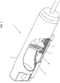
- Figure 1 shows a piston-and-cylinder assembly 1 with a portion of the cylindrical casing 3 cut away to reveal a piston head 5 that moves along the axis of a cylindrical casing 3.
- the cylindrical casing 3 is made from aluminium.
- a position sensor for detecting the position of the piston head 5 along the axis the cylindrical casing 3 includes a permanent magnet 7 forming part of the piston head 5 and a planar structure 9 located outside of the cylindrical casing 3 within a separate casing 11 (part of which is cut away in Figure 1 to reveal the planar structure 9).
- part of the piston head 5 has also been cut away to indicate that the permanent magnet 7 has a generally annular shape.
- the poles of the permanent magnet 7 are provided on opposing faces of the annulus such that the north pole faces one way along the axis of the cylindrical casing 3 and the south pole faces the other way along the axis of the cylindrical casing 3.
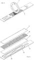
- the planar structure 9 has a printed circuit (PCB) 21 carrying conductive tracks forming a transmit aerial 23 and a receive aerial 25.
- the transmit aerial 23 and the receive aerial 25 are the same as the corresponding structures described in International patent publication no. WO 03/038379 (the whole contents of which are hereby incorporated herein by reference).
- excitation signal generating and detection signal processing circuitry identical to that described in WO 03/038379 applies excitation signals to the transmit aerial 23 and processes signals induced in the receive aerial 25 to determine a position reading.
- a spacer layer 27 is formed over the transmit aerial 23 and the receive aerial 25.
- the spacer layer 27 is formed of an insulating material, in this embodiment a bonding tape such as 3MTM VHBTM tape.
- a patterned film 29 of magnetisable material is formed over the spacer layer 27.
- the magnetisable material is a Nickel-Iron alloy commonly referred to as Mu-metal. Mu-metal has a high relative permeability (of the order of 100,000) and a low saturation flux density.
- the high relative permeability of Mu-metal means that a continuous film of Mu-metal provides a low reluctance path for magnetic fields.
- the film 29 of Mu-metal is not continuous, but is instead patterned in order to reduce, in effect, the reluctance of the Mu-metal film along a path following the axis of the cylindrical casing 3.
- the Mu-metal film is formed by a linear array of strips arranged parallel to each other along the axis of the cylinder casing 3 and crossing the axis at an oblique angle, the strips being separated by gaps.
- a layer 31 of conductive material is formed over the patterned Mu-metal film 29.
- the conductive material is copper.
- the conductive layer 31 allows the flow of eddy currents that would otherwise be inhibited by the patterned Mu-metal film 29. In this way, the signal level in the receive aerial 25 is increased to a level comparable to that obtained using a continuous film of magnetisable material.
- the transmit aerial 23 and the receive aerial 25 are balanced such that a magnetic field generated by current flow in the transmit aerial 23 induces a nett null signal in the receive aerial 25.
- the DC magnetic field generated by the permanent magnet 7 passes though the cylinder casing 3 and the casing 11 and saturates the adjacent region of the patterned Mu-metal film 29.
- the layout of the conductive tracks forming the transmit aerial 23 and the receive aerial 25 is such that this saturation causes an imbalance in the magnetic coupling between the transmit aerial 23 and the receive aerial 25 that is dependent on the position of the localised saturated region, and that imbalance causes a detection signal to be generated in the conductive track forming the receive aerial 25 that is indicative of the position of the permanent magnet 7 within the cylindrical casing 3.
- a detection signal is generated in the receive aerial 25 that has a phase that is indicative of the position of the permanent magnet 7, and accordingly the piston head 5, within the cylindrical casing 3.
- the excitation signal generating and detection signal processing circuitry which as mentioned above is identical to that in WO 03/038379 , processes detection signal induced in the receive aerial 25 to determine a position reading.
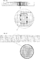
- the magnetisable film 29 is patterned into an array of diagonal stripes separated by gaps, as shown in Figure 4A .
- Figures 4B to 4F show, by way of example, alternative possible patterns for the magnetisable film 29.
- FIGS 4B to 4F show, by way of example, alternative possible patterns for the magnetisable film 29.
- the width of the stripes can be in the region of 3mm while the width of the gaps between stripes can be in the region of 0.2mm. These values are, however, given purely by way of example and many different dimensions can be used.
- the strips could alternatively have a width in the range of 0.5mm to 1mm with gaps of about 20 microns provided therebetween.
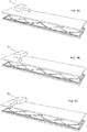
- poles of the permanent magnet 7 are aligned along the axis of the cylindrical casing 3.
- this configuration has the advantage that rotation of the piston head 5 about the axis will have no effect on the magnetic field generated by the permanent magnet 7.
- Other orientations of the poles of the permanent magnet 7 are, however, possible.
- one pole of an alternative permanent magnet 51 could face toward the planar structure 9 while the other pole faces away from the planar structure 9.
- one pole of another alternative permanent magnet 53 could face in a direction parallel to the planar structure 9 but perpendicular to the measurement direction while the other pole faces the opposite direction.
- a portion of the magnetisable film 29 adjacent to the magnet saturates, although the exact shape of the saturated region varies dependent on the orientation of the magnet and the patterning of the magnetisable film 29.
- FIG. 4E shows an example of such a design, in which a portion of the pattern has been magnified with an eddy current path 41 within a saturated region (indicated by the dotted pattern) of the Mu-metal superimposed.
- the bridge portions of Mu-metal are sufficiently small to be magnetically insignificant. Further, providing bridges can provide greater mechanical stability that is useful during fabrication.
- the size of the localised saturated region can be controlled by using isolated regions of Mu-metal, such as shown in Figure 4F .
- the controlling of the spot size may be particularly advantageous at the end regions of the sensor range in order to limit the impact of end effects.
- the patterning illustrated in Figure 4F is well suited to the orientation of the permanent magnet 53 as illustrated in Figure 5C .
- segmenting the Mu-metal film along and perpendicular to the measurement direction, as shown in Figure 4F has been found to provide a reduced spot size in comparison to segmenting the Mu-metal film only along the measurement direction, i.e. as shown in Figure 4B .
- providing the gaps in the Mu-metal film restricts the area of the localised saturated region.
- Such patterns may, for example, include hexagonal regions of Mu-metal or two shape patterns of Mu-metal.
- the shapes of the Mu-metal regions and the size of the gaps can allow control of magnetic flux in at least one direction, hence controlling the size and the shape of the saturation area.
- the pattern of the extent of Mu-metal varies along the measurement direction to control the linearity of a position signal.
- the film 29 of Mu-metal is patterned by forming uniform regions of Mu-metal separated by gaps.
- Other forms of patterning are available that improve the immunity of the position sensor to external magnetic fields. For example:
- a property of the Mu-metal film is non-uniform in order to increase the effective reluctance of the Mu-metal film in one or more directions in order to reduce the amount of flux of an external magnetic field channelled through the Mu-metal film in comparison with a uniform extent of Mu-metal, so as to improve the immunity of the position sensor to external magnetic fields.
- a position sensor having a non-uniform Mu-metal film in accordance to the present invention can operate in the presence of external magnetic fields at least two times higher than a position sensor having a uniform Mu-metal film whose thickness matches the maximum thickness of the non-uniform Mu-metal film and whose permeability matched the maximum permeability of the non-uniform Mu-metal film.
- the Mu-metal film can be made non-uniform in different ways.
- a uniform film of Mu-metal is deposited and then etched away in accordance with a pattern to generate the non-uniform thickness.
- the uniform film of Mu-metal may be etched before being deposited.
- regions of Mu-metal can be cut away, either mechanically using, for example, a dicing saw or using a laser cutter.
- a uniform film of Mu-metal is mechanically worked to form a pattern of non-uniformity, for example by impressing a pattern in the Mu-metal film to form dented regions of Mu-metal or by inscribing a pattern in the uniform film of Mu-metal.
- Such inscribing may cause one or more of i) the thickness of the inscribed regions of Mu-metal being reduced, and ii) the permeability of the inscribed regions of Mu-metal being reduced.
- Such a process can result in the film of Mu-metal having a corrugated configuration.
- a film of Mu-metal having non-uniform relative permeability can also be generated by thermally working the Mu-metal in accordance with a pattern.
- non-uniformity there are different manufacturing processes associated with different forms of non-uniformity, and accordingly different manufacturing costs.
- the chosen form of non-uniformity will depend on achieving a desired level of performance at a desired cost.
- a single Mu-metal film is formed to one side of the PCB 21.
- two or more Mu-metal films are formed.
- a Mu-metal film could be formed on each side of the PCB 21 or two Mu-metal films could be formed on the same side of the PCB 21 but separated by an insulating layer (such as a plastic material).
- the two layers of Mu-metal could have complementary patterns.
- Bonding tape is provided as a spacer layer 27 between the Mu-metal film and the transmit and receive aerials in the above embodiments.
- spacer layer 27 between the Mu-metal film and the transmit and receive aerials in the above embodiments.
- PCB substrate material e.g. FR4 glass epoxy
- FR4 glass epoxy could be used.
- the magnetisable material forming the patterned film is Mu-metal.
- suitable nickel-iron alloys such as permalloy, silicon-iron alloys or cobalt-iron alloys.
- the magnetisable material can be in the form of an amorphous alloy, such as VITRO VACTM available from Vacuumschmelze, or in the form of a nanocrystalline alloy, such as VITROPERMTM available from Vacuumschmelze.
- the conductive layer 31 is not necessary for the invention to function and is accordingly an optional feature. Also, the conductive layer 31 could be patterned in the same manner as the magnetisable material, while still providing eddy paths (see, for example, the pattern of Figure 4E ) for simplicity of manufacturing.
- the position sensor is used to determine the position of a piston head 5 along a measurement path within a cylindrical casing 3.
- the piston head 5 forms a first member
- the cylindrical casing 3 forms a second member
- the axis of the cylindrical casing 3 forms a measurement direction such that the position sensor detects the position of a first member relative to a second member along the measurement path.
- Position sensors implementing the present invention have, however, broader utility than just measuring the position of a piston head within a cylinder.
- the present invention is particularly useful when a property of the extent of magnetisable material is non-uniform along the measurement path, particularly when the measurement path is rectilinear as the problem of saturation by an external magnetic field is most prevalent for rectilinear strips of magnetisable material, that is not essential and some benefit may be obtained, for example, even in a rotary position sensor in which the measurement path is circular.
- the non-uniformity is in a repeating pattern along at least one direction.
- a repeating pattern of non-uniformity may be present in one or both of the lengthwise and widthwise directions. It is preferred that the period of the repeating pattern is less than the spot size of the localised saturated region.
- a non-repeating pattern will work, for example a series of rectangular stripes of magnetisable material having a progressively larger length along the measurement direction.
- the non-uniformity acts to reduce the distortion of an external magnetic field due to the presence of the extent of magnetisable material. It will be appreciated that this is significantly different from shielding, which is designed to suck in as much magnetic flux as possible of the external magnetic field.
- the DC magnetic field may be generated by an electromagnet instead of a passive permanent magnet.
- a magnetic field generator either having a magnetic field or being operable to generate a magnetic field.
- the present invention is also applicable to the position sensors discussed in WO 2005/085763 , US 2001/0052771 and US 4774465 (or other types of permanent magnet linear contactless displacement sensor (PLCD)).
- PLCD permanent magnet linear contactless displacement sensor
- having a transmit aerial and a receive aerial is not essential, although at least one conductive winding is required for which at least a component of a signal in the at least one conductive winding is dependent on the position of the localised saturated region of the magnetisable material.
- the component of the signal is dependent on the position of the localised saturated region of the magnetisable material.
- the present invention would also apply to a position sensor having a core of magnetisable material instead of a film of magnetisable material formed on a substrate. What is required is an extent of magnetisable material of which a localised region is saturated by a magnetic field generator.
- the extent of magnetisable material will have a profile along the measurement direction, with a property of that profile being non-uniform within a measurement range of operation so that the effective reluctance of the extent of magnetisable material is increased. This reduces the amount of the external magnetic field flux carried by the extent of magnetisable material, thereby improving the immunity of the position sensor to external magnetic fields.
- non-uniformity impacts the performance in the presence of an external magnetic field. If the non-uniformity is formed by introducing gaps into the extent of magnetisable material, performance is greatly improved; both the accuracy of position readings and the ability to measure position at external field strengths for which an equivalent sensor with a uniform extent of magnetisable material would lose signal. Other nonuniformities may not produce such significant accuracy improvements, but still offer the ability to measure position at external field strengths for which an equivalent sensor with a uniform extent of magnetisable material would lose signal.
Landscapes
- Physics & Mathematics (AREA)
- General Physics & Mathematics (AREA)
- Transmission And Conversion Of Sensor Element Output (AREA)
- Measurement Of Length, Angles, Or The Like Using Electric Or Magnetic Means (AREA)
Claims (14)
- Positionssensor zum Bestimmen der relativen Position zwischen einem ersten Element (3) und einem zweiten Element (5), wobei der Positionssensor umfasst:eine Sendeantenne (23) und eine Empfangsantenne (25), die relativ zum ersten Element (3) angeordnet sind;einen Magnetfeldgenerator (7), der relativ zum zweiten Element (5) angeordnet ist, wobei der Magnetfeldgenerator (7) entweder ein Magnetfeld aufweist oder betreibbar ist, um ein Magnetfeld zu erzeugen; undeine Ausdehnung eines magnetisierbaren Materials (29),wobei das Magnetfeld, das mit dem Magnetfeldgenerator (7) assoziiert ist, betreibbar ist, um einen lokalisierten Bereich der Ausdehnung des magnetisierbaren Bereichs zu sättigen, wobei die Position des lokalisierten gesättigten Bereichs relativ zum ersten Element abhängig von der Position des zweiten Elements (5) relativ zum ersten Element (3) ist, und die Anordnung der Leiterbahnen, die die Sendeantenne (23) und die Empfangsantenne (25) bilden, so ist, dass diese Sättigung ein Ungleichgewicht in der Kopplung zwischen der Sendeantenne und der Empfangsantenne verursacht, die abhängig von der Position des lokalisierten gesättigten Bereichs ist, um eine positionsabhängige Komponente in ein Signal in die Empfangsantenne (25) einzubringen, das in Übereinstimmung mit der Position des lokalisierten gesättigten Bereichs ist, undwobei eine Eigenschaft der Ausdehnung des magnetisierbaren Materials (29) ungleichförmig ist, wodurch die effektive Reluktanz der Ausdehnung des magnetisierbaren Materials (29) in zumindest einer Richtung erhöht wird.
- Positionssensor nach Anspruch 1, wobei der Positionssensor eingerichtet ist, die relative Position zwischen dem ersten Element (3) und dem zweiten Element (5) entlang eines Messwegs zu bestimmen, und wobei die Eigenschaft der Ausdehnung des magnetisierbaren Materials (29) ungleichförmig entlang dem Messweg ist.
- Positionssensor nach Anspruch 2, wobei das Profil der Ausdehnung des magnetisierbaren Materials (29) entlang dem Messweg ungleichförmig ist.
- Positionssensor nach einem der vorhergehenden Ansprüche, wobei die Ungleichförmigkeit der Ausdehnung des magnetisierbaren Materials (29) Lücken in der Ausdehnung des magnetisierbaren Materials umfasst.
- Positionssensor nach Anspruch 4, wobei die Ausdehnung des magnetisierbaren Materials (29) sich in einer größeren Distanz in einer Längsrichtung als in einer breiten Richtung erstreckt und die Lücken angeordnet sind, um die Reluktanz der Ausdehnung des magnetisierbaren Materials (29) entlang der Längsrichtung zu erhöhen.
- Positionssensor nach Anspruch 4 oder 5, wobei die Ausdehnung des magnetisierbaren Materials (29) eine Schicht eines magnetisierbaren Materials umfasst, die eine Anordnung von Inseln aus magnetisierbarem Material umfasst, wobei zumindest einige der Inseln aus magnetisierbarem Material durch Brückenabschnitte von magnetisierbarem Material miteinander verbunden sind.
- Positionssensor nach Anspruch 6, wobei die Brückenabschnitte angeordnet sind, um Leiterpfade (41) für Wirbelströme bereitzustellen.
- Positionssensor nach Anspruch 6 oder 7, wobei die Inseln des magnetisierbaren Materials in der Form sind von:einer Reihe von diagonalen Streifen relativ zur Längsrichtung, wobei die Lücken zwischen benachbarten diagonalen Streifen gebildet sind, odereiner Reihe von Streifen in Breitenrichtung, wobei die Lücken zwischen benachbarten Streifen geformt sind; eine Reihe von Winkeln, wobei die Lücken zwischen benachbarten Winkeln gebildet sind; odereine mosaikartige Anordnung von Formen, wobei die Lücken zwischen den Formen gebildet sind.
- Positionssensor nach einem der Ansprüche 6 bis 8, wobei der Magnetfeldgenerator (7) erste und zweite Pole aufweist, die in einer Richtung senkrecht zu einer Richtung der Messung des Positionssensors und parallel zur Schicht des magnetisierbaren Materials ausgerichtet sind.
- Positionssensor nach einem oder mehreren der vorhergehenden Ansprüche, wobei die Ungleichförmigkeit der Ausdehnung des magnetisierbaren Materials (29) eingerichtet ist, um gleichförmige Bereiche des magnetisierbaren Materials zu definieren, die eingerichtet sind, um die Größe des lokalisierten gesättigten Bereichs im Vergleich mit einer gesamten Ausdehnung des magnetisierbaren Materials, die die Gleichförmigkeit aufweist, zu reduzieren.
- Positionssensor nach einem der vorhergehenden Ansprüche, wobei die Ungleichförmigkeit der Ausdehnung des magnetisierbaren Materials (29) in einem wiederholenden Muster entlang der mindestens einen Richtung ist,
wobei die Periode des sich wiederholenden Musters in der mindestens einen Richtung geringer als die Größe des lokalisierten gesättigten Bereichs ist. - Positionssensor nach einem der vorhergehenden Ansprüche, wobei die Ungleichförmigkeit der Ausdehnung des magnetisierbaren Materials (29) die Sättigung der Ausdehnung des magnetisierbaren Materials hemmt.
- Positionssensor nach einem der vorhergehenden Ansprüche, wobei die Ausdehnung des magnetisierbaren Materials (29) einen Film eines magnetisierbaren Materials umfasst, und der Positionssensor ferner eine Schicht aus leitfähigem Material umfasst, die in dem Film des magnetisierbaren Materials bereitgestellt ist.
- Positionssensor nach einem der vorhergehenden Ansprüche, wobei die Ungleichförmigkeit entlang des Messwegs variiert, um die Linearität der positionsabhängigen Komponente in Position zu steuern.
Applications Claiming Priority (2)
| Application Number | Priority Date | Filing Date | Title |
|---|---|---|---|
| GB201404688A GB201404688D0 (en) | 2014-03-17 | 2014-03-17 | Position sensing apparatus and method |
| PCT/EP2015/055370 WO2015140080A1 (en) | 2014-03-17 | 2015-03-13 | Position sensing apparatus and method |
Publications (2)
| Publication Number | Publication Date |
|---|---|
| EP3120113A1 EP3120113A1 (de) | 2017-01-25 |
| EP3120113B1 true EP3120113B1 (de) | 2019-07-31 |
Family
ID=50634864
Family Applications (1)
| Application Number | Title | Priority Date | Filing Date |
|---|---|---|---|
| EP15713660.7A Active EP3120113B1 (de) | 2014-03-17 | 2015-03-13 | Positionssensor |
Country Status (3)
| Country | Link |
|---|---|
| EP (1) | EP3120113B1 (de) |
| GB (1) | GB201404688D0 (de) |
| WO (1) | WO2015140080A1 (de) |
Families Citing this family (2)
| Publication number | Priority date | Publication date | Assignee | Title |
|---|---|---|---|---|
| US12013264B2 (en) | 2018-10-16 | 2024-06-18 | Kyocera Avx Components (Werne) Gmbh | Position sensing apparatus and method |
| US11703359B2 (en) | 2019-05-14 | 2023-07-18 | Kyocera Avx Components (Werne) Gmbh | Inductive position sensing apparatus including a screening layer and method for the same |
Family Cites Families (4)
| Publication number | Priority date | Publication date | Assignee | Title |
|---|---|---|---|---|
| US6605939B1 (en) * | 1999-09-08 | 2003-08-12 | Siemens Vdo Automotive Corporation | Inductive magnetic saturation displacement sensor |
| FR2860070A1 (fr) * | 2003-09-22 | 2005-03-25 | Siemens Vdo Automotive | Capteur de deplacement et son application notamment a la detection des variations de la hauteur d'une suspension de vehicule automobile |
| US7868609B2 (en) * | 2004-03-01 | 2011-01-11 | Sagentia Limited | Position sensor |
| WO2008032008A1 (en) * | 2006-09-14 | 2008-03-20 | Sagentia Limited | Position sensor |
-
2014
- 2014-03-17 GB GB201404688A patent/GB201404688D0/en not_active Ceased
-
2015
- 2015-03-13 WO PCT/EP2015/055370 patent/WO2015140080A1/en not_active Ceased
- 2015-03-13 EP EP15713660.7A patent/EP3120113B1/de active Active
Also Published As
| Publication number | Publication date |
|---|---|
| EP3120113A1 (de) | 2017-01-25 |
| GB201404688D0 (en) | 2014-04-30 |
| WO2015140080A1 (en) | 2015-09-24 |
Similar Documents
| Publication | Publication Date | Title |
|---|---|---|
| EP3954972B1 (de) | Magnetoresistiver trägheitssensorchip | |
| EP1721130B1 (de) | Positionssensor | |
| US6714004B2 (en) | Inductive position measuring system | |
| US5831431A (en) | Miniaturized coil arrangement made by planar technology, for the detection of ferromagnetic materials | |
| CN101520493B (zh) | 薄膜磁传感器 | |
| EP2525193B1 (de) | Magnetischer Näherungssensor | |
| US6690164B1 (en) | Perpendicular detection fluxgate micromagnetometer and method for the production thereof | |
| JP3946629B2 (ja) | プリント回路基板に集積された磁界検出素子の製造方法 | |
| JP2011163832A5 (de) | ||
| KR101532150B1 (ko) | 직교형 플럭스게이트 센서 | |
| EP1139069A1 (de) | Magnetfeldsensor und Positionsdetektor | |
| US11703359B2 (en) | Inductive position sensing apparatus including a screening layer and method for the same | |
| EP1146319B1 (de) | Positionsgeber | |
| EP3120113B1 (de) | Positionssensor | |
| US20170234703A1 (en) | Position sensor | |
| TW200402526A (en) | Magnetic position sensor | |
| DK2834601T3 (en) | Method and device for positioning a component | |
| JP3880922B2 (ja) | 半導体基板に集積された磁界検出素子及びその製造方法 | |
| US20180313666A1 (en) | Sensor arrangement and method for determining a position and/or a change in the position of a measurement object | |
| JP5870554B2 (ja) | エンコーダ | |
| JP5374741B2 (ja) | 多重冗長型リニアセンサ | |
| JP4110468B2 (ja) | 磁気インピーダンス素子 | |
| JP5374739B2 (ja) | リニアセンサ | |
| JP5668211B2 (ja) | リニアセンサ | |
| US12247852B2 (en) | Magnetic sensor |
Legal Events
| Date | Code | Title | Description |
|---|---|---|---|
| STAA | Information on the status of an ep patent application or granted ep patent |
Free format text: STATUS: THE INTERNATIONAL PUBLICATION HAS BEEN MADE |
|
| PUAI | Public reference made under article 153(3) epc to a published international application that has entered the european phase |
Free format text: ORIGINAL CODE: 0009012 |
|
| STAA | Information on the status of an ep patent application or granted ep patent |
Free format text: STATUS: REQUEST FOR EXAMINATION WAS MADE |
|
| 17P | Request for examination filed |
Effective date: 20161017 |
|
| AK | Designated contracting states |
Kind code of ref document: A1 Designated state(s): AL AT BE BG CH CY CZ DE DK EE ES FI FR GB GR HR HU IE IS IT LI LT LU LV MC MK MT NL NO PL PT RO RS SE SI SK SM TR |
|
| AX | Request for extension of the european patent |
Extension state: BA ME |
|
| DAV | Request for validation of the european patent (deleted) | ||
| DAX | Request for extension of the european patent (deleted) | ||
| STAA | Information on the status of an ep patent application or granted ep patent |
Free format text: STATUS: EXAMINATION IS IN PROGRESS |
|
| 17Q | First examination report despatched |
Effective date: 20180213 |
|
| GRAP | Despatch of communication of intention to grant a patent |
Free format text: ORIGINAL CODE: EPIDOSNIGR1 |
|
| STAA | Information on the status of an ep patent application or granted ep patent |
Free format text: STATUS: GRANT OF PATENT IS INTENDED |
|
| INTG | Intention to grant announced |
Effective date: 20190212 |
|
| GRAS | Grant fee paid |
Free format text: ORIGINAL CODE: EPIDOSNIGR3 |
|
| GRAA | (expected) grant |
Free format text: ORIGINAL CODE: 0009210 |
|
| STAA | Information on the status of an ep patent application or granted ep patent |
Free format text: STATUS: THE PATENT HAS BEEN GRANTED |
|
| AK | Designated contracting states |
Kind code of ref document: B1 Designated state(s): AL AT BE BG CH CY CZ DE DK EE ES FI FR GB GR HR HU IE IS IT LI LT LU LV MC MK MT NL NO PL PT RO RS SE SI SK SM TR |
|
| REG | Reference to a national code |
Ref country code: CH Ref legal event code: EP Ref country code: GB Ref legal event code: FG4D |
|
| REG | Reference to a national code |
Ref country code: AT Ref legal event code: REF Ref document number: 1161388 Country of ref document: AT Kind code of ref document: T Effective date: 20190815 |
|
| REG | Reference to a national code |
Ref country code: IE Ref legal event code: FG4D |
|
| REG | Reference to a national code |
Ref country code: DE Ref legal event code: R096 Ref document number: 602015034744 Country of ref document: DE |
|
| REG | Reference to a national code |
Ref country code: NL Ref legal event code: MP Effective date: 20190731 |
|
| REG | Reference to a national code |
Ref country code: LT Ref legal event code: MG4D |
|
| REG | Reference to a national code |
Ref country code: AT Ref legal event code: MK05 Ref document number: 1161388 Country of ref document: AT Kind code of ref document: T Effective date: 20190731 |
|
| PG25 | Lapsed in a contracting state [announced via postgrant information from national office to epo] |
Ref country code: LT Free format text: LAPSE BECAUSE OF FAILURE TO SUBMIT A TRANSLATION OF THE DESCRIPTION OR TO PAY THE FEE WITHIN THE PRESCRIBED TIME-LIMIT Effective date: 20190731 Ref country code: FI Free format text: LAPSE BECAUSE OF FAILURE TO SUBMIT A TRANSLATION OF THE DESCRIPTION OR TO PAY THE FEE WITHIN THE PRESCRIBED TIME-LIMIT Effective date: 20190731 Ref country code: NL Free format text: LAPSE BECAUSE OF FAILURE TO SUBMIT A TRANSLATION OF THE DESCRIPTION OR TO PAY THE FEE WITHIN THE PRESCRIBED TIME-LIMIT Effective date: 20190731 Ref country code: AT Free format text: LAPSE BECAUSE OF FAILURE TO SUBMIT A TRANSLATION OF THE DESCRIPTION OR TO PAY THE FEE WITHIN THE PRESCRIBED TIME-LIMIT Effective date: 20190731 Ref country code: BG Free format text: LAPSE BECAUSE OF FAILURE TO SUBMIT A TRANSLATION OF THE DESCRIPTION OR TO PAY THE FEE WITHIN THE PRESCRIBED TIME-LIMIT Effective date: 20191031 Ref country code: PT Free format text: LAPSE BECAUSE OF FAILURE TO SUBMIT A TRANSLATION OF THE DESCRIPTION OR TO PAY THE FEE WITHIN THE PRESCRIBED TIME-LIMIT Effective date: 20191202 Ref country code: NO Free format text: LAPSE BECAUSE OF FAILURE TO SUBMIT A TRANSLATION OF THE DESCRIPTION OR TO PAY THE FEE WITHIN THE PRESCRIBED TIME-LIMIT Effective date: 20191031 Ref country code: SE Free format text: LAPSE BECAUSE OF FAILURE TO SUBMIT A TRANSLATION OF THE DESCRIPTION OR TO PAY THE FEE WITHIN THE PRESCRIBED TIME-LIMIT Effective date: 20190731 Ref country code: HR Free format text: LAPSE BECAUSE OF FAILURE TO SUBMIT A TRANSLATION OF THE DESCRIPTION OR TO PAY THE FEE WITHIN THE PRESCRIBED TIME-LIMIT Effective date: 20190731 |
|
| PG25 | Lapsed in a contracting state [announced via postgrant information from national office to epo] |
Ref country code: IS Free format text: LAPSE BECAUSE OF FAILURE TO SUBMIT A TRANSLATION OF THE DESCRIPTION OR TO PAY THE FEE WITHIN THE PRESCRIBED TIME-LIMIT Effective date: 20191130 Ref country code: RS Free format text: LAPSE BECAUSE OF FAILURE TO SUBMIT A TRANSLATION OF THE DESCRIPTION OR TO PAY THE FEE WITHIN THE PRESCRIBED TIME-LIMIT Effective date: 20190731 Ref country code: GR Free format text: LAPSE BECAUSE OF FAILURE TO SUBMIT A TRANSLATION OF THE DESCRIPTION OR TO PAY THE FEE WITHIN THE PRESCRIBED TIME-LIMIT Effective date: 20191101 Ref country code: AL Free format text: LAPSE BECAUSE OF FAILURE TO SUBMIT A TRANSLATION OF THE DESCRIPTION OR TO PAY THE FEE WITHIN THE PRESCRIBED TIME-LIMIT Effective date: 20190731 Ref country code: LV Free format text: LAPSE BECAUSE OF FAILURE TO SUBMIT A TRANSLATION OF THE DESCRIPTION OR TO PAY THE FEE WITHIN THE PRESCRIBED TIME-LIMIT Effective date: 20190731 Ref country code: ES Free format text: LAPSE BECAUSE OF FAILURE TO SUBMIT A TRANSLATION OF THE DESCRIPTION OR TO PAY THE FEE WITHIN THE PRESCRIBED TIME-LIMIT Effective date: 20190731 |
|
| PG25 | Lapsed in a contracting state [announced via postgrant information from national office to epo] |
Ref country code: TR Free format text: LAPSE BECAUSE OF FAILURE TO SUBMIT A TRANSLATION OF THE DESCRIPTION OR TO PAY THE FEE WITHIN THE PRESCRIBED TIME-LIMIT Effective date: 20190731 |
|
| PG25 | Lapsed in a contracting state [announced via postgrant information from national office to epo] |
Ref country code: PL Free format text: LAPSE BECAUSE OF FAILURE TO SUBMIT A TRANSLATION OF THE DESCRIPTION OR TO PAY THE FEE WITHIN THE PRESCRIBED TIME-LIMIT Effective date: 20190731 Ref country code: DK Free format text: LAPSE BECAUSE OF FAILURE TO SUBMIT A TRANSLATION OF THE DESCRIPTION OR TO PAY THE FEE WITHIN THE PRESCRIBED TIME-LIMIT Effective date: 20190731 Ref country code: EE Free format text: LAPSE BECAUSE OF FAILURE TO SUBMIT A TRANSLATION OF THE DESCRIPTION OR TO PAY THE FEE WITHIN THE PRESCRIBED TIME-LIMIT Effective date: 20190731 Ref country code: IT Free format text: LAPSE BECAUSE OF FAILURE TO SUBMIT A TRANSLATION OF THE DESCRIPTION OR TO PAY THE FEE WITHIN THE PRESCRIBED TIME-LIMIT Effective date: 20190731 Ref country code: RO Free format text: LAPSE BECAUSE OF FAILURE TO SUBMIT A TRANSLATION OF THE DESCRIPTION OR TO PAY THE FEE WITHIN THE PRESCRIBED TIME-LIMIT Effective date: 20190731 |
|
| PG25 | Lapsed in a contracting state [announced via postgrant information from national office to epo] |
Ref country code: SM Free format text: LAPSE BECAUSE OF FAILURE TO SUBMIT A TRANSLATION OF THE DESCRIPTION OR TO PAY THE FEE WITHIN THE PRESCRIBED TIME-LIMIT Effective date: 20190731 Ref country code: SK Free format text: LAPSE BECAUSE OF FAILURE TO SUBMIT A TRANSLATION OF THE DESCRIPTION OR TO PAY THE FEE WITHIN THE PRESCRIBED TIME-LIMIT Effective date: 20190731 Ref country code: CZ Free format text: LAPSE BECAUSE OF FAILURE TO SUBMIT A TRANSLATION OF THE DESCRIPTION OR TO PAY THE FEE WITHIN THE PRESCRIBED TIME-LIMIT Effective date: 20190731 Ref country code: IS Free format text: LAPSE BECAUSE OF FAILURE TO SUBMIT A TRANSLATION OF THE DESCRIPTION OR TO PAY THE FEE WITHIN THE PRESCRIBED TIME-LIMIT Effective date: 20200224 |
|
| REG | Reference to a national code |
Ref country code: DE Ref legal event code: R097 Ref document number: 602015034744 Country of ref document: DE |
|
| PLBE | No opposition filed within time limit |
Free format text: ORIGINAL CODE: 0009261 |
|
| STAA | Information on the status of an ep patent application or granted ep patent |
Free format text: STATUS: NO OPPOSITION FILED WITHIN TIME LIMIT |
|
| PG2D | Information on lapse in contracting state deleted |
Ref country code: IS |
|
| PG25 | Lapsed in a contracting state [announced via postgrant information from national office to epo] |
Ref country code: IS Free format text: LAPSE BECAUSE OF FAILURE TO SUBMIT A TRANSLATION OF THE DESCRIPTION OR TO PAY THE FEE WITHIN THE PRESCRIBED TIME-LIMIT Effective date: 20191030 |
|
| 26N | No opposition filed |
Effective date: 20200603 |
|
| PG25 | Lapsed in a contracting state [announced via postgrant information from national office to epo] |
Ref country code: SI Free format text: LAPSE BECAUSE OF FAILURE TO SUBMIT A TRANSLATION OF THE DESCRIPTION OR TO PAY THE FEE WITHIN THE PRESCRIBED TIME-LIMIT Effective date: 20190731 |
|
| PG25 | Lapsed in a contracting state [announced via postgrant information from national office to epo] |
Ref country code: MC Free format text: LAPSE BECAUSE OF FAILURE TO SUBMIT A TRANSLATION OF THE DESCRIPTION OR TO PAY THE FEE WITHIN THE PRESCRIBED TIME-LIMIT Effective date: 20190731 |
|
| REG | Reference to a national code |
Ref country code: CH Ref legal event code: PL |
|
| REG | Reference to a national code |
Ref country code: BE Ref legal event code: MM Effective date: 20200331 |
|
| PG25 | Lapsed in a contracting state [announced via postgrant information from national office to epo] |
Ref country code: LU Free format text: LAPSE BECAUSE OF NON-PAYMENT OF DUE FEES Effective date: 20200313 |
|
| PG25 | Lapsed in a contracting state [announced via postgrant information from national office to epo] |
Ref country code: LI Free format text: LAPSE BECAUSE OF NON-PAYMENT OF DUE FEES Effective date: 20200331 Ref country code: IE Free format text: LAPSE BECAUSE OF NON-PAYMENT OF DUE FEES Effective date: 20200313 Ref country code: CH Free format text: LAPSE BECAUSE OF NON-PAYMENT OF DUE FEES Effective date: 20200331 Ref country code: FR Free format text: LAPSE BECAUSE OF NON-PAYMENT OF DUE FEES Effective date: 20200331 |
|
| REG | Reference to a national code |
Ref country code: DE Ref legal event code: R082 Ref document number: 602015034744 Country of ref document: DE Representative=s name: KALKOFF & PARTNER PATENTANWAELTE MBB, DE |
|
| REG | Reference to a national code |
Ref country code: DE Ref legal event code: R081 Ref document number: 602015034744 Country of ref document: DE Owner name: KYOCERA AVX COMPONENTS (WERNE) GMBH, DE Free format text: FORMER OWNERS: AB ELEKTRONIK GMBH, 59368 WERNE, DE; TT ELECTRONICS TECHNOLOGY LIMITED, HARSTON, CAMBRIDGESHIRE, GB Ref country code: DE Ref legal event code: R082 Ref document number: 602015034744 Country of ref document: DE Representative=s name: KALKOFF & PARTNER PATENTANWAELTE MBB, DE Ref country code: DE Ref legal event code: R081 Ref document number: 602015034744 Country of ref document: DE Owner name: AB ELEKTRONIK GMBH, DE Free format text: FORMER OWNERS: AB ELEKTRONIK GMBH, 59368 WERNE, DE; TT ELECTRONICS TECHNOLOGY LIMITED, HARSTON, CAMBRIDGESHIRE, GB |
|
| PG25 | Lapsed in a contracting state [announced via postgrant information from national office to epo] |
Ref country code: BE Free format text: LAPSE BECAUSE OF NON-PAYMENT OF DUE FEES Effective date: 20200331 |
|
| GBPC | Gb: european patent ceased through non-payment of renewal fee |
Effective date: 20200313 |
|
| PG25 | Lapsed in a contracting state [announced via postgrant information from national office to epo] |
Ref country code: GB Free format text: LAPSE BECAUSE OF NON-PAYMENT OF DUE FEES Effective date: 20200313 |
|
| REG | Reference to a national code |
Ref country code: DE Ref legal event code: R081 Ref document number: 602015034744 Country of ref document: DE Owner name: KYOCERA AVX COMPONENTS (WERNE) GMBH, DE Free format text: FORMER OWNER: AB ELEKTRONIK GMBH, 59368 WERNE, DE |
|
| PG25 | Lapsed in a contracting state [announced via postgrant information from national office to epo] |
Ref country code: MT Free format text: LAPSE BECAUSE OF FAILURE TO SUBMIT A TRANSLATION OF THE DESCRIPTION OR TO PAY THE FEE WITHIN THE PRESCRIBED TIME-LIMIT Effective date: 20190731 Ref country code: CY Free format text: LAPSE BECAUSE OF FAILURE TO SUBMIT A TRANSLATION OF THE DESCRIPTION OR TO PAY THE FEE WITHIN THE PRESCRIBED TIME-LIMIT Effective date: 20190731 |
|
| PG25 | Lapsed in a contracting state [announced via postgrant information from national office to epo] |
Ref country code: MK Free format text: LAPSE BECAUSE OF FAILURE TO SUBMIT A TRANSLATION OF THE DESCRIPTION OR TO PAY THE FEE WITHIN THE PRESCRIBED TIME-LIMIT Effective date: 20190731 |
|
| P01 | Opt-out of the competence of the unified patent court (upc) registered |
Effective date: 20230529 |
|
| PGFP | Annual fee paid to national office [announced via postgrant information from national office to epo] |
Ref country code: DE Payment date: 20260213 Year of fee payment: 12 |