EP3120355B1 - Suppression de bruit - Google Patents
Suppression de bruit Download PDFInfo
- Publication number
- EP3120355B1 EP3120355B1 EP15707356.0A EP15707356A EP3120355B1 EP 3120355 B1 EP3120355 B1 EP 3120355B1 EP 15707356 A EP15707356 A EP 15707356A EP 3120355 B1 EP3120355 B1 EP 3120355B1
- Authority
- EP
- European Patent Office
- Prior art keywords
- tile
- noise
- time frequency
- frequency
- tiles
- Prior art date
- Legal status (The legal status is an assumption and is not a legal conclusion. Google has not performed a legal analysis and makes no representation as to the accuracy of the status listed.)
- Active
Links
Images


Classifications
-
- G—PHYSICS
- G10—MUSICAL INSTRUMENTS; ACOUSTICS
- G10L—SPEECH ANALYSIS TECHNIQUES OR SPEECH SYNTHESIS; SPEECH RECOGNITION; SPEECH OR VOICE PROCESSING TECHNIQUES; SPEECH OR AUDIO CODING OR DECODING
- G10L21/00—Speech or voice signal processing techniques to produce another audible or non-audible signal, e.g. visual or tactile, in order to modify its quality or its intelligibility
- G10L21/02—Speech enhancement, e.g. noise reduction or echo cancellation
- G10L21/0208—Noise filtering
- G10L21/0216—Noise filtering characterised by the method used for estimating noise
- G10L21/0232—Processing in the frequency domain
-
- G—PHYSICS
- G10—MUSICAL INSTRUMENTS; ACOUSTICS
- G10L—SPEECH ANALYSIS TECHNIQUES OR SPEECH SYNTHESIS; SPEECH RECOGNITION; SPEECH OR VOICE PROCESSING TECHNIQUES; SPEECH OR AUDIO CODING OR DECODING
- G10L21/00—Speech or voice signal processing techniques to produce another audible or non-audible signal, e.g. visual or tactile, in order to modify its quality or its intelligibility
- G10L21/02—Speech enhancement, e.g. noise reduction or echo cancellation
- G10L21/0208—Noise filtering
-
- G—PHYSICS
- G10—MUSICAL INSTRUMENTS; ACOUSTICS
- G10L—SPEECH ANALYSIS TECHNIQUES OR SPEECH SYNTHESIS; SPEECH RECOGNITION; SPEECH OR VOICE PROCESSING TECHNIQUES; SPEECH OR AUDIO CODING OR DECODING
- G10L21/00—Speech or voice signal processing techniques to produce another audible or non-audible signal, e.g. visual or tactile, in order to modify its quality or its intelligibility
- G10L21/04—Time compression or expansion
-
- G—PHYSICS
- G10—MUSICAL INSTRUMENTS; ACOUSTICS
- G10L—SPEECH ANALYSIS TECHNIQUES OR SPEECH SYNTHESIS; SPEECH RECOGNITION; SPEECH OR VOICE PROCESSING TECHNIQUES; SPEECH OR AUDIO CODING OR DECODING
- G10L25/00—Speech or voice analysis techniques not restricted to a single one of groups G10L15/00 - G10L21/00
- G10L25/03—Speech or voice analysis techniques not restricted to a single one of groups G10L15/00 - G10L21/00 characterised by the type of extracted parameters
- G10L25/18—Speech or voice analysis techniques not restricted to a single one of groups G10L15/00 - G10L21/00 characterised by the type of extracted parameters the extracted parameters being spectral information of each sub-band
-
- H—ELECTRICITY
- H04—ELECTRIC COMMUNICATION TECHNIQUE
- H04R—LOUDSPEAKERS, MICROPHONES, GRAMOPHONE PICK-UPS OR LIKE ACOUSTIC ELECTROMECHANICAL TRANSDUCERS; ELECTRIC HEARING AIDS; PUBLIC ADDRESS SYSTEMS
- H04R3/00—Circuits for transducers
- H04R3/005—Circuits for transducers for combining the signals of two or more microphones
-
- G—PHYSICS
- G10—MUSICAL INSTRUMENTS; ACOUSTICS
- G10L—SPEECH ANALYSIS TECHNIQUES OR SPEECH SYNTHESIS; SPEECH RECOGNITION; SPEECH OR VOICE PROCESSING TECHNIQUES; SPEECH OR AUDIO CODING OR DECODING
- G10L21/00—Speech or voice signal processing techniques to produce another audible or non-audible signal, e.g. visual or tactile, in order to modify its quality or its intelligibility
- G10L21/02—Speech enhancement, e.g. noise reduction or echo cancellation
- G10L21/0208—Noise filtering
- G10L2021/02087—Noise filtering the noise being separate speech, e.g. cocktail party
-
- G—PHYSICS
- G10—MUSICAL INSTRUMENTS; ACOUSTICS
- G10L—SPEECH ANALYSIS TECHNIQUES OR SPEECH SYNTHESIS; SPEECH RECOGNITION; SPEECH OR VOICE PROCESSING TECHNIQUES; SPEECH OR AUDIO CODING OR DECODING
- G10L21/00—Speech or voice signal processing techniques to produce another audible or non-audible signal, e.g. visual or tactile, in order to modify its quality or its intelligibility
- G10L21/02—Speech enhancement, e.g. noise reduction or echo cancellation
- G10L21/0208—Noise filtering
- G10L21/0216—Noise filtering characterised by the method used for estimating noise
- G10L2021/02161—Number of inputs available containing the signal or the noise to be suppressed
- G10L2021/02165—Two microphones, one receiving mainly the noise signal and the other one mainly the speech signal
-
- G—PHYSICS
- G10—MUSICAL INSTRUMENTS; ACOUSTICS
- G10L—SPEECH ANALYSIS TECHNIQUES OR SPEECH SYNTHESIS; SPEECH RECOGNITION; SPEECH OR VOICE PROCESSING TECHNIQUES; SPEECH OR AUDIO CODING OR DECODING
- G10L21/00—Speech or voice signal processing techniques to produce another audible or non-audible signal, e.g. visual or tactile, in order to modify its quality or its intelligibility
- G10L21/02—Speech enhancement, e.g. noise reduction or echo cancellation
- G10L21/0208—Noise filtering
- G10L21/0216—Noise filtering characterised by the method used for estimating noise
- G10L2021/02161—Number of inputs available containing the signal or the noise to be suppressed
- G10L2021/02166—Microphone arrays; Beamforming
Definitions
- the invention relates to noise suppression and in particular, but not exclusively, to suppression of non-stationary diffuse noise based on signals captured from two microphones.
- a problem in many scenarios and applications is that the desired speech source is typically not the only audio source in the environment. Rather, in typical audio environments there are many other audio/ noise sources which are being captured by the microphone.
- One of the critical problems facing many speech capturing applications is that of how to best extract speech in a noisy environment. In order to address this problem a number of different approaches for noise suppression have been proposed.
- US2012322511 proposes de-noising the audio signals picked up by multichannel, multi-microphone system in an environment that is very noisy and very reverberant, typically the cabin of a car. US2012322511 takes into account a reverberant environment that makes it impossible to calculate an arrival direction of the useful signal in satisfactory manner, and also to obtain de-noising that reproduces both the amplitude and the phase of the initial signal, i.e. without deforming the speaker's voice when it is played back by the device. US2012322511 provides description of a technique that is implemented in the frequency domain on a plurality of bins of the signal that is picked up (i.e. on each frequency band of each time frame of the signal).
- the processing consists essentially in: calculating the probability that speech is present in the noisy signal as picked up; estimating the transfer functions of the acoustic channels between the speech source (the near speaker) and each of the sensors of the array of microphones; calculating an optimal projection for determining a single channel on the basis of the estimated transfer functions of the multiple channels; and selectively reducing noise in this single channel, for each bin, as a function of the probability that speech is present.
- Diffuse noise is for example an acoustic (noise) sound field in a room where the noise is coming from all directions.
- a typical example is so-called "babble"-noise in e.g. a cafeteria or restaurant in which there are many noise sources distributed across the room.
- the desired speech is captured in addition to background noise.
- Speech enhancement can be used to try to modify the microphone signal such that the background noise is reduced while the desired speech is as unaffected as possible.
- the noise is diffuse, one proposed approach is to try to estimate the spectral amplitude of the background noise and to modify the spectral amplitude such that the spectral amplitude of the resulting enhanced signal resembles the spectral amplitude of the desired speech signal as much as possible.
- the phase of the captured signal is not changed in this approach.
- FIG. 1 illustrates an example of a noise suppression system in accordance with prior art.
- input signals are received from two microphones with one being considered to be a reference microphone and the other being a main microphone capturing the desired audio source, and specifically capturing speech.
- a reference microphone signal x(n) and a primary microphone signal are received.
- the signals are converted to the frequency domain in transformers 101, 103, and the magnitude in individual time frequency tiles are generated by magnitude units 105, 107.
- the resulting magnitude values are fed to a unit 109 for calculating gains.
- the frequency domain values of the primary signal are multiplied by the resulting gains in a multiplier 111 thereby generating a frequency spectrum compensated output signal which is converted to the time domain in another transform unit 113.
- Frequency domain signals are first generated by computing a short-time Fourier transform (STFT) of e.g. overlapping Hanning windowed blocks of the time domain signal.
- STFT short-time Fourier transform
- the microphone signal is fed to a post-processor which performs noise suppression by modifying the spectral amplitude of the input signal while leaving the phase unchanged.
- the time domain signal is reconstructed by combining the current and the previous frame taking into account that the original time signal was windowed and time overlapped (i.e. an overlap-and-add procedure is performed).
- the primary microphone contains the desired speech component as well as a noise component
- the reference microphone signal can be assumed to not contain any speech but only a noise signal recorded at the position of the reference microphone.
- C t k , ⁇ l E
- the coherence term is an indication of the average correlation between the amplitudes of the noise component in the primary microphone signal and the amplitudes of the reference microphone signal.
- C ( t k , ⁇ l ) is not dependent on the instantaneous audio at the microphones but instead depends on the spatial characteristics of the noise sound field, the variation of C ( t k , ⁇ l ) as a function of time is much less than the time variations of Z n and X n .
- C ( t k , ⁇ l ) can be estimated relatively accurately by averaging
- An approach for doing so is disclosed in US7602926 , which specifically describes a method where no explicit speech detection is needed for determining C ( t k, ⁇ l ) .
- G t k , ⁇ l M A X
- the described approach may provide advantageous performance in many scenarios, it may in some scenarios provide less than optimum performance.
- the noise suppression may be less than optimum.
- the improvement in the Signal-to-Noise-Ratio (SNR) may be limited, and often the so-called SNR Improvement (SNRI) is in practice found to be limited to around 6-9dB.
- SNR Improvement SNR Improvement
- this may be acceptable in some applications, it will in many scenarios tend to result in a significant remaining noise component degrading the perceived speech quality.
- other noise suppression techniques can be used, these tend to also be suboptimal and e.g. tend to be complex, inflexible, impractical, computationally demanding, require complex hardware (e.g. a high number of microphones), and/or provide suboptimal noise suppression.
- an improved noise suppression would be advantageous, and in particular a noise suppression allowing reduced complexity, increased flexibility, facilitated implementation, reduced cost (e.g. not requiring a large number of microphones), improved noise suppression and/or improved performance would be advantageous.
- the Invention seeks to preferably mitigate, alleviate or eliminate one or more of the above mentioned disadvantages singly or in any combination.
- a noise suppressor for suppressing noise in a first microphone signal
- the noise suppressor comprising: a first transformer for generating a first frequency domain signal from a frequency transform of a first microphone signal, the first frequency domain signal being represented by time frequency tile values; a second transformer for generating a second frequency domain signal from a frequency transform of a second microphone signal, the second frequency domain signal being represented by time frequency tile values; a gain unit for determining time frequency tile gains as a non-negative monotonic function of a difference measure being indicative of a difference between a first monotonic function of a magnitude time frequency tile value of the first frequency domain signal and a second monotonic function of a magnitude time frequency tile value of the second frequency domain signal; and a scaler for generating an output frequency domain signal by scaling time frequency tile values of the first frequency domain signal by the time frequency tile gains; the noise suppressor further comprising: a designator for designating time frequency tiles of the first frequency domain signal as speech tiles or noise tiles; and wherein the gain unit is arranged
- the invention may provide improved and/or facilitated noise suppression in many embodiments.
- the invention may allow improved suppression of non-stationary and/or diffuse noise.
- An increased signal or speech to noise ratio can often be achieved, and in particular, the approach may in practice increase the upper bound on the potential SNR improvement.
- the invention may allow an improvement in SNR of the noise suppressed signal from around 6-8 dB to in excess of 20 dB.
- the approach may typically provide improved noise suppression, and may in particular allow improved suppression of noise without a corresponding suppression of speech.
- An improved signal to noise ratio of the suppressed signal may often be achieved.
- the gain unit is arranged to determine different time frequency tile gains separately for at least two time frequency tiles.
- the time frequency tiles may be divided into a plurality of sets of time frequency tiles, and the gain unit may be arranged to independently and/or separately determine gains for each of the sets of time frequency tiles.
- the gain for time frequency tiles of one set of time frequency tiles may depend on properties of the first frequency domain signal and the second frequency domain signal only in the time frequency tiles belonging to the set of time frequency tiles.
- the gain unit determines different gains for a time frequency tile if this is designated as a speech tile than if it is designated as a noise tile.
- the gain unit may specifically be arranged to calculate the gain for a time frequency tile by evaluating a function, the function being dependent on the designation of the time frequency tile.
- the gain unit may be arranged to calculate the gain for a time frequency tile by evaluating a different function when the time frequency tile is designated as a speech tile than if it is designated as a noise tile.
- a function, equation, algorithm, and/or parameter used in determining a time frequency tile gain may be different when the time frequency tile is designated as a speech tile than if it is designated as a noise tile.
- a time frequency tile may specifically correspond to one bin of the frequency transform in one time segment/ frame.
- the first and second transformers may use block processing to transform consecutive segments of the first and second signal.
- a time frequency tile may correspond to a set of transform bins (typically one) in one segment/ frame.
- the designation as speech or noise (time frequency) tiles may in some embodiments be performed individually for each time frequency tile. However, often a designation may apply to a group of time frequency tiles. Specifically, a designation may apply to all time frequency tiles in one time segment. Thus, in some embodiments, the first microphone signal may be segmented into transform time segments/ frames which are individually transformed to the frequency domain, and a designation of the time frequency tiles as speech or noise tiles may be common for all time frequency tiles of one segment/ frame.
- the noise suppressor may further comprise a third transformer for generating an output signal from a frequency to time transform of the output frequency domain signal.
- the output frequency domain signal may be used directly. For example, speech recognition or enhancement may be performed in the frequency domain and may accordingly directly use the output frequency domain signal without requiring any conversion to the time domain.
- the gain unit is arranged to determine a gain value for a time frequency tile gain of a time frequency tile as a function of the difference measure for the time frequency tile.
- This may provide an efficient noise suppression and/or facilitated implementation.
- it may in many embodiments result in efficient noise suppression which adapts efficiently to the signal characteristics, yet may be implemented without requiring high computational loads or extremely complex processing.
- the function is a monotonic function of the difference measure, and the gain value may specifically be proportional to the difference value.
- At least one of the first monotonic function and the second monotonic function is dependent on whether the time frequency tile is designated as a speech tile or as a noise tile.
- This may provide an efficient noise suppression and/or facilitated implementation.
- it may in many embodiments result in efficient noise suppression which adapts efficiently to the signal characteristics, yet may be implemented without requiring high computational loads or extremely complex processing.
- the at least one of the first monotonic function and the second monotonic function provides a different output value for the same magnitude time frequency tile value of the first, respectively second, frequency domain signal, for the time frequency tile when the time frequency tile is designated as a speech tile than when it is designated a noise tile.
- the second monotonic function comprises a scaling of the magnitude time frequency tile value of the second frequency domain signal for the time frequency tile with a scale value dependent on whether the time frequency tile is designated as a speech time frequency tile or a noise time frequency tile.
- This may provide an efficient noise suppression and/or facilitated implementation.
- it may in many embodiments result in efficient noise suppression which adapts efficiently to the signal characteristics, yet may be implemented without requiring high computational loads or extremely complex processing.
- the gain unit is arranged to generate a noise coherence estimate indicative of a correlation between an amplitude of the second microphone signal and an amplitude of a noise component of the first microphone signal and at least one of the first monotonic function and the second monotonic function is dependent on the noise coherence estimate.
- the noise coherence estimate may specifically be an estimate of the correlation between the amplitudes of the first microphone signal and the amplitudes of the second microphone signal when there is no speech, i.e. when the speech source is inactive.
- the noise coherence estimate may in some embodiments be determined based on the first and second microphone signals, and/or the first and second frequency domain signals. In some embodiments, the noise correlation estimate may be generated based on a separate calibration or measurement process.
- the first monotonic function and the second monotonic function are such that an expected value of the difference measure is negative if an amplitude relationship between the first microphone signal and the second microphone signal corresponds to the noise coherence estimate and the time frequency tile is designated as a noise tile.
- the gain unit is arranged to vary at least one of the first monotonic function and the second monotonic function such that the expected value of the difference measure for the amplitude relationship between the first microphone signal and the second microphone signal corresponding to the noise coherence estimate is different for a time frequency tile designated as a noise tile than for a time frequency tile designated as a speech tile.
- a gain difference for a time frequency tile being designated as a speech tile and a noise tile is dependent on at least one value from the group consisting of: a signal level of the first microphone signal; a signal level of the second microphone signal; and a signal to noise estimate for the first microphone signal.
- This may provide an efficient noise suppression and/or facilitated implementation.
- it may in many embodiments result in efficient noise suppression which adapts efficiently to the signal characteristics yet may be implemented without requiring high computational loads or extremely complex processing.
- the difference measure for a time frequency tile is dependent on whether the time frequency tile is designated as a noise tile or a speech tile.
- the designator is arranged to designate time frequency tiles of the first frequency domain signal as speech tiles or noise tiles in response to difference values generated in response to the difference measure for a noise tile to the magnitude time frequency tile values of the first frequency domain signal and magnitude time frequency tile values of the second frequency domain signal.
- This may allow for a particularly advantageous designation.
- a reliable designation may be achieved while at the same time allowing reduced complexity. It may specifically allow corresponding, or typically the same, functionality to be used for both the designation of tiles as for the gain determination.
- the designator is arranged to designate a time frequency tile as a noise tile if the difference value is below a threshold.
- the designator is arranged to filter difference values over a plurality of time frequency tiles, the filtering including time frequency tiles differing in both time and frequency.
- the gain unit is arranged to filter gain values over a plurality of time frequency tiles, the filtering including time frequency tiles differing in both time and frequency.
- the approach may improve noise suppression by applying a filtering to a gain value for a time frequency tile where the filtering is both a frequency and time filtering.
- the gain unit is arranged to filter at least one of the magnitude time frequency tile values of the first frequency domain signal and the magnitude time frequency tile values of the second frequency domain signal; the filtering including time frequency tiles differing in both time and frequency.
- the approach may improve noise suppression by applying a filtering to a signal value for a time frequency tile where the filtering is both a frequency and time filtering.
- the gain unit is arranged to filter both the magnitude time frequency tile values of the first frequency domain signal and the magnitude time frequency tile values of the second frequency domain signal; where the filtering includes time frequency tiles differing in both time and frequency.
- the noise suppressor further comprises an audio beamformer arranged to generate the first microphone signal and the second microphone signal from signals from a microphone array.
- This may improve performance and may allow improved signal to noise ratios of the suppressed signal.
- the approach may allow a reference signal with reduced contribution from the desired source to be processed by the algorithm to provide improved designation and/or noise suppression.
- the noise suppressor further comprises an adaptive canceller for cancelling a signal component of the first microphone signal correlated with the second microphone signal from the first microphone signal.
- This may improve performance and may allow improved signal to noise ratios of the suppressed signal.
- the approach may allow a reference signal with reduced contribution from the desired source to be processed by the algorithm to provide improved designation and/or noise suppression.
- the difference measure is determined as a difference between a first value given as a monotonic function of a magnitude time frequency tile value of the first frequency domain signal and a second value given as a monotonic function of a magnitude time frequency tile value of the second frequency domain signal.
- a method of suppressing noise in a first microphone signal comprising: generating a first frequency domain signal from a frequency transform of a first microphone signal, the first frequency domain signal being represented by time frequency tile values; generating a second frequency domain signal from a frequency transform of a second microphone signal, the second frequency domain signal being represented by time frequency tile values; determining time frequency tile gains in response to a difference measure for magnitude time frequency tile values of the first frequency domain signal and magnitude time frequency tile values of the second frequency domain signal; and generating an output frequency domain signal by scaling time frequency tile values of the first frequency domain signal by the time frequency tile gains; the method further comprising: designating time frequency tiles of the first frequency domain signal as speech tiles or noise tiles; and wherein the time frequency tile gains are determined in response to the designation of the time frequency tiles of the first frequency domain signal as speech tiles or noise tiles.
- the method may further comprise the step of generating an output signal from a frequency to time transform of the output frequency domain signal.
- the inventors of the current application have realized that the performance of the prior art approach of FIG. 1 tends to provide suboptimal performance for non-stationary/ diffuse noise, and have furthermore realized that improvements are possible by introducing specific concepts that can mitigate or eliminated restrictions on performance experienced by the system of FIG. 1 for non-stationary/ diffuse noise.
- the inventors have realized that the approach of FIG. 1 for diffuse noise has a limited Signal-to-Noise-Ratio Improvement (SNRI) range.
- SNRI Signal-to-Noise-Ratio Improvement
- the inventors have realized that when increasing the oversubtraction factor ⁇ n in the conventional functions as previously set out, other disadvantageous effects may be introduced, and specifically that an increase in speech attenuation during speech may result.
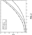
- X 1 ( t k , ⁇ l ) and X 2 ( t k , ⁇ l ) are uncorrelated for higher frequencies and large distances. If, for example, the distance is larger than 3 meters, then for frequencies above 200 Hz X 1 ( t k , ⁇ l ) and X 2 ( t k , ⁇ l ) are substantially uncorrelated.
- the attenuation is limited to a relatively low value of less than 7 dB for the case where only background noise is present.
- the attenuation is as a function of the oversubtraction factor ⁇ n for some exemplary values may thus be as follows: ⁇ n A [dB] 1 6.7 1.2 7.8 1.4 8.8 1.6 9.7 1.8 10.6 2.0 11.4 4.0 17.0
- the total SNR improvement is limited to around 12 dB.
- FIG. 4 illustrates an example of a noise suppressor in accordance with some embodiments of the invention.
- the noise suppressor of FIG. 4 may provide substantially higher SNR improvements for diffuse noise than is typically possible with the system of FIG. 1 . Indeed, simulations and practical tests have demonstrated that SNR improvements in excess of 20-30 dB are typically possible.
- the noise suppressor comprises a first transformer 401 which receives a first microphone signal from a microphone (not shown).
- the first microphone signal may be captured, filtered, amplified etc. as known in the prior art.
- the first microphone signal may be a digital time domain signal generated by sampling an analog signal.
- the first transformer 401 is arranged to generate a first frequency domain signal by applying a frequency transform to the first microphone signal.
- the first microphone signal is divided into time segments/ intervals.
- Each time segment/ interval comprises a group of samples which are transformed, e.g. by an FFT, into a group of frequency domain samples.
- the first frequency domain signal is represented by frequency domain samples where each frequency domain sample corresponds to a specific time interval and a specific frequency interval.
- Each such frequency interval and time interval is typically in the field known as a time frequency tile.
- the first frequency domain signal is represented by a value for each of a plurality of time frequency tiles, i.e. by time frequency tile values.
- the noise suppressor further comprises a second transformer 403 which receives a second microphone signal from a microphone (not shown).
- the second microphone signal may be captured, filtered, amplified etc. as known in the prior art.
- the second microphone signal may be a digital time domain signal generated by sampling an analog signal.
- the second transformer 403 is arranged to generate a second frequency domain signal by applying a frequency transform to the second microphone signal.
- the second microphone signal is divided into time segments/ intervals.
- Each time segment/ interval comprises a group of samples which are transformed, e.g. by an FFT, into a group of frequency domain samples.
- the second frequency domain signal is represented a value for each of a plurality of time frequency tiles, i.e. by time frequency tile values.
- the first and second microphone signals are in the following referred to as z(n) and x(n) respectively and the first and second frequency domain signals are referred to by the vectors Z ( M ) ( t k ) and X ( M ) ( t k ) (each vector comprising all M frequency tile values for a given processing/ transform time segment/ frame).
- z(n) When in use, z(n) is assumed to comprise noise and speech whereas x(n) is assumed to comprise noise only. Furthermore, the noise components of z(n) and x(n) are assumed to be uncorrelated (The components are assumed to be uncorrelated in time. However, there is assumed to typically be a relation between the average amplitudes and this relation is represented by the coherence term).
- the real and imaginary components of the time frequency values are assumed to be Gaussian distributed. This assumption is typically accurate e.g. for scenarios with noise originating from diffuse sound fields, for sensor noise, and for a number of other noise sources experienced in many practical scenarios.
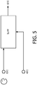
- FIG. 6 illustrates a specific example of functional elements of possible implementations of the first and second transform units 401, 403.
- a serial to parallel converter generates overlapping blocks (frames) of 2B samples which are then Hanning windowed and converted to the frequency domain by a Fast Fourier Transform (FFT) .
- FFT Fast Fourier Transform
- the first transformer 401 is coupled to a first magnitude unit 405 which determines the magnitude values of the time frequency tile values thus generating magnitude time frequency tile values for the first frequency domain signal.
- the second transformer 403 is coupled to a second magnitude unit 407 which determines the magnitude values of the time frequency tile values thus generating magnitude time frequency tile values for the second frequency domain signal.
- the first and second magnitude units 405, 407 are fed to a gain unit 409 which is arranged to determine gains for the time frequency tiles based on the magnitude time frequency tile values of the first frequency domain signal and magnitude time frequency tile values of the second frequency domain signal.
- the gain unit 409 thus calculates time frequency tile gains which in the following are referred to by the vectors G ⁇ _ M t k .
- the gain unit 409 specifically determines a difference measure indicative of a difference between time frequency tile values of the first frequency domain signal and predicted time frequency tile values of the first frequency domain signal generated from the time frequency tile values of the second frequency domain signal.
- the difference measure may thus specifically be a prediction difference measure.
- the prediction may simply be that the time frequency tile values of the second frequency domain signal are a direct prediction of the time frequency tile values of the first frequency domain signal.
- the gain is then determined as a function of the difference measure. Specifically, a difference measure may be determined for each time frequency tile and the gain may be set such that the higher the difference measure (i.e. the stronger indication of difference) the higher the gain. Thus, the gain may be determined as a monotonically increasing function of the distance measure.
- time frequency tile gains are determined with gains being lower for time frequency tiles for which the difference measure is relatively low, i.e. for time frequency tiles where the value of the first frequency domain signal can relatively accurately be predicted from the value of the second frequency domain signal, than for time frequency tiles for which the difference measure is relatively low, i.e. for time frequency tiles where the value of the first frequency domain signal cannot effectively be predicted from the value of the second frequency domain signal.
- gains for time frequency tiles where there is high probability of the first frequency domain signal containing a significant speech component are determined as higher than gains for time frequency tiles where there is low probability of the first frequency domain signal containing a significant speech component.
- the generated time frequency tile gains are in the example scalar values.
- the gain unit 409 is coupled to a scaler 411 which is fed the gains, and which proceeds to scale the time frequency tile values of the first frequency domain signal by these time frequency tile gains. Specifically, in the scaler 411, the signal vector Z ( M ) ( t k ) is elementwise multiplied by the gain vector G ⁇ _ M t k to yield the resulting signal vector Q ( M ) ( t k )
- the scaler 411 thus generates a third frequency domain signal, also referred to as an output frequency domain signal, which corresponds to the first frequency domain signal but with a spectral shaping corresponding to the expected speech component.
- a third frequency domain signal also referred to as an output frequency domain signal
- the individual time frequency tile values of the first frequency domain signal may be scaled in amplitude but the time frequency tile values of the third frequency domain signal will have the same phase as the corresponding values of the first frequency domain signal.
- the gain unit 409 is coupled to an optional third transformer 413 which is fed the third frequency domain signal.
- the third transformer 413 is arranged to generate an output signal from a frequency to time transform of the third frequency domain signal.
- the third transformer 413 may perform the inverse transform of the transform of the first frequency domain signal by the first transformer 401.
- the third (output) frequency domain signal may be used directly, e.g. by frequency domain speech recognition or speech enhancement. In such embodiments, there is accordingly no need for the third transformer 413.
- the third frequency domain signal Q ( M ) ( t k ) may be transformed back to the time domain and then, because of the overlapping and windowing of the first microphone signal by the first transformer 401, the time domain signal may be reconstructed by adding the first B samples of the current (newest) frame (transform segment) with the last B samples of the previous frame. Finally the resulting block q ( B ) ( t k ) can be transformed into a continuous output signal stream q(n) by a parallel to serial converter.
- the noise suppressor of FIG. 4 does not base the calculation of the time frequency tile gains on only the difference measures. Rather, the noise suppressor is arranged to designate time frequency tiles as being speech (time frequency) tiles or being noise (time frequency tiles), and to determine the gains in dependence on the designation of the designation. Specifically, the function for determining a gain for a given time frequency tile as a function of the difference measure will be different if the time frequency tile is designated as belonging to a speech frame than if it is designated as a belonging to a noise frame.
- the noise suppressor of FIG. 4 specifically comprises a designator 415 which is arranged to designate time frequency tiles of the first frequency domain signal as speech tiles or noise tiles.
- time frequency tiles are into speech and non-speech tiles.
- noise tiles may be considered equivalent to non-speech tiles (indeed as the desired signal component is a speech component, all non-speech can be considered to be noise).
- the designation of time frequency tiles as speech or noise (time frequency) tiles may be based on a comparison of the first and second microphone signals, and/or a comparison of the first and second frequency domain signals. Specifically, the closer the correlation between the amplitude of the signals, the less likely it is that the first microphone signal comprises significant speech components.
- time frequency tiles as speech or noise tiles (where each category in some embodiments may comprise further subdivisions into subcategories) may in some embodiments be performed individually for each time frequency tile but may also in many embodiments be performed in groups of time frequency tiles.
- the designator 415 is arranged to generate one designation for each time segment/ transform block.
- the designator 415 may be estimated whether the first microphone signal comprises a significant speech component or not. If so, all time frequency tiles of that time segment are designated as speech time frequency tiles and otherwise they are designated as noise time frequency tiles.
- the designator 415 is coupled to the first and second magnitude units 405, 407 and is arranged to designate the time frequency tiles based on the magnitude values of the first and second frequency domain signals.
- the designation may alternatively or additionally be based on e.g. the first and second microphone signal and/or the first and second frequency domain signal.
- the designator 415 is coupled to the gain unit 409 which is fed the designations of the time frequency tiles, i.e. the gain unit 409 receives information as to which time frequency tiles are designated as speech tiles and which time frequency tiles are designated as noise tiles.
- the gain unit 409 is arranged to calculate the time frequency tile gains in response to the designation of the time frequency tiles of the first frequency domain signal as speech tiles or noise tiles.
- the gain calculation is dependent on the designation, and the resulting gain will be different for time frequency tiles that are designated as speech tiles than for time frequency tiles that are designated as noise tiles.
- This difference or dependency may for example be implemented by the gain unit 409 by this having two alternative algorithms or functions for calculating a gain value from a difference measure and being arranged to select between these two functions for the time frequency tiles based on the designation.
- the gain unit 409 may use different parameter values for a single function with the parameter values being dependent on the designation.
- the gain unit 409 is arranged to determine a lower gain value for a time frequency tile gain when the corresponding time frequency tile is designated as a noise tile than when it is designated as a speech tile. Thus, if all other parameters used to determine the gains are unchanged, the gain unit 409 will calculate a lower gain value for a noise tile than for a speech tile.
- the designation is segment/ frame based, i.e. the same designation is applied to all time frequency tiles of a time segment/ frame. Accordingly, the gains for the time segments/ frames estimated to comprise sufficient speech are set higher than for the time segments estimated not to comprise sufficient speech (all other parameters being equal).
- the difference value for a time frequency tile may be dependent on whether the time frequency tile is designated as a noise tile or a speech tile.
- the same function may be used to calculate the gain from a difference measure, but the calculation of the difference measure itself may depend on the designation of the time frequency tiles.
- the difference measure may be determined as a function of the magnitude time frequency tile values of the first and second frequency domain signals respectively.
- the difference measure may be determined as a difference between a first and a second value wherein the first value is generated as a function of at least one time frequency tile value of the first frequency domain signal and the second value is generates as a function of at least one time frequency tile value of the second frequency domain signal.
- the first value may not be dependent on the at least one time frequency tile value of the second frequency domain signal, and the second value may not be dependent on the at least one time frequency tile value of the first frequency domain signal.
- a first value for a first time frequency tile may specifically be generated as a monotonically increasing function of the magnitude time frequency tile value of the first frequency domain signal in the first time frequency tile.
- a second value for the first time frequency tile may specifically be generated as a monotonically increasing function of the magnitude time frequency tile value of the second frequency domain signal in the second time frequency tile.
- At least one of the functions for calculating the first and second values may be dependent on whether the time frequency tile is designated as a speech time frequency tile or a noise time frequency tile.
- the first value may be higher if the time frequency tile is a speech tile than if it is a noise tile.
- the second value may be lower if the time frequency tile is a speech tile than if it is a noise tile.
- , for a noise frame G t k , ⁇ l
- C ( t k , ⁇ l ) is an estimated coherence term representing correlation between the amplitudes of the first frequency domain signal and the amplitudes of the second frequency domain signal
- the oversubtraction factor ⁇ n is a design parameter
- the gain function is limited to positive values, and typically a minimum gain value is set.
- , ⁇ for a noise frame
- G t k , ⁇ l M A X
- the gain is thus determined as a function of a numerator which is a difference measure.
- the difference measure is determined as the difference between two terms (values).
- the first term/ value is a function of the magnitude of the time frequency tile value of the first frequency domain signal.
- the second term/ value is a function of the magnitude of the time frequency tile value of the second frequency domain signal.
- the function for calculating the second value is further dependent on whether the time frequency tile is designated as a noise or speech time frequency tile (i.e. it is dependent on whether the time frequency tile is part of a noise or speech frame).
- the gain unit 409 is arranged to determine a noise coherence estimate C ( t k, ⁇ l ). indicative of a correlation between the amplitude of the second microphone signal and the amplitude of a noise component of the first microphone signal.
- the function for determining the second value (or in some cases the first value) is in this case dependent on this noise coherence estimate. This allows a more appropriate determination of an appropriate gain value since the second value more accurately reflects the expected or estimated noise component in the first frequency domain signal.
- any suitable approach for determining the noise coherence estimate C ( t k , ⁇ l ) may be used.
- a calibration may be performed where the speaker is instructed not to speak with the first and second frequency domain signal being compared and with the noise correlation estimate C ( t k , ⁇ l ) for each time frequency tile simply being determined as the average ratio of the time frequency tile values of the first frequency domain signal and the second frequency domain signal.
- the dependency on the gain of whether a time frequency tile is designated as a speech tile or as a noise tile is not a constant value but is itself dependent on one or more parameters.
- the factor ⁇ may in some embodiments not be constant but rather may be a function of characteristics of the receive signals (whether direct or derived characteristics).
- the gain difference may be dependent on at least one of a signal level of the first microphone signal; a signal level of the second microphone signal; and a signal to noise estimate for the first microphone signal.
- These values may be average values over a plurality of time frequency tiles, and specifically over a plurality of frequency values and a plurality of segments. They may specifically be (relatively long term) measures for the signals as a whole.
- ⁇ is dependent on a signal to noise ratio for the first microphone signal. This may provide improved perceived noise suppression. In particular, for low signal to noise ratios, a strong noise suppression is performed thereby improving e.g. intelligibility of the speech in the resulting signal. However, for higher signal to noise ratios, the effect is reduced thereby reducing distortion.
- the function f ( - v 2 /2 ⁇ 2 ) can be determined and used to adapt the calculation of the gains for speech signals.
- the function depends on (- v 2 /2 ⁇ 2 ), which corresponds to the SNR: i.e. the energy of the speech signal v 2 versus the noise energy 2 ⁇ 2 .
- the difference measure is indicative of a difference between a first monotonic function f 1 (x) of a magnitude time frequency tile value of the first frequency domain signal and a second monotonic function f 1 (x) of a magnitude time frequency tile value of the second frequency domain signal.
- the first and second monotonic functions may be identical functions. However, in most embodiments, the two functions will be different.
- one or both of the functions f 1 (x) and f 2 (x) may be dependent on various other parameters and measures, such as for example an overall averaged power level of the microphone signals, the frequency, etc.
- one or both of the functions f 1 (x) and f 2 (x) may be dependent on signal values for other frequency tiles, for example by an averaging of one or more of Z ( t k , ⁇ l ),
- an averaging over a neighborhood extending in both the time and frequency dimensions may be performed.
- Specific examples based on the specific difference measure equations provided earlier will be described later but it will be appreciated that corresponding approaches may also be applied to other algorithms or functions determining the difference measure.
- ⁇ ( ⁇ l ) may be used to provide the desired spectral characteristics of the noise suppression while keeping the spectral shaping of the speech to a low level.
- the factor ⁇ represents a factor which is introduced to bias the difference measure towards negative values. It will be appreciated that whereas the specific examples introduce this bias by a simple scale factor applied to the second microphone signal time frequency tile, many other approaches are possible.
- any suitable way of arranging the first and second functions f 1 (x) and f 2 (x) in order to provide a bias towards negative values for at least noise tiles may be used.
- the bias is specifically, as in the previous examples, a bias that will generate expected values of the difference measure which are negative if there is no speech. Indeed, if both the first and second microphone signals contain only random noise (e.g. the sample values may be symmetrically and randomly distributed around a mean value), the expected value of the difference measure will be negative rather than zero. In the previous specific example, this was achieved by the oversubtraction factor ⁇ which resulted in negative values when there is no speech.
- the gain unit may as previously described determine a noise coherence estimate which is indicative of a correlation between an amplitude of the second microphone signal and an amplitude of a noise component of the first microphone signal.
- the noise coherence estimate may for example be generated as an estimate of the ratio between the amplitude of the first microphone signal and the second microphone signal.
- the noise coherence estimate may be determined for individual frequency bands, and may specifically be determined for each time frequency tile.
- Various techniques for estimating amplitude/ magnitude relationships between two microphone signals are known to the skilled person and will not be described in further detail. For example, average amplitude estimates for different frequency bands may be determined during time intervals with no speech (e.g. by a dedicated manual measurement or by automatic detection of speech pauses).
- At least one of the first and second monotonic functions f 1 (x) and f 2 (x) may compensate for the amplitude differences.
- the second monotonic function compensated for the amplitude differences by scaling the magnitude values of the second microphone signal by the value C ( t k , ⁇ l ).
- the compensation may alternatively or additionally be performed by the first monotonic function, e.g. by scaling magnitude values of the first microphone signal by 1/ C ( t k , ⁇ l ) .
- the first monotonic function and the second monotonic function are such that a negative expected value for the difference measure is generated if an amplitude relationship between the first microphone signal and the second microphone signal corresponds to the estimated correlation, and if the time frequency tile is designated as a noise tile.
- the noise coherence estimate may indicate that an estimated or expected magnitude difference between the first microphone signal and the second microphone signal (and specifically for the specific frequency band) corresponds to the ratio given by the value of C ( t k , ⁇ l ) .
- the first monotonic function and the second monotonic function are selected such that if the corresponding time frequency tile values have magnitude values that are equal to C ( t k, ⁇ l ) (and if the time frequency tile is designated a noise tile) then the generated difference measure will be negative.
- the first and second monotonic functions f 1 (x) and f 2 (x) is selected with the property that if
- C t k , ⁇ l then the difference measure d ( t k , ⁇ l ) will have a negative value (when designated a noise tile), i.e.
- the first and second monotonic functions f 1 (x) and f 2 (x) are selected such that for noise tiles d t k , ⁇ l ⁇ 0 f o r
- C t k , ⁇ l
- the compensation for noise level differences between the first and second microphone signals, as well as the bias towards negative difference measure values is achieved by including compensation factors in the second monotonic function f 2 (x).
- this may alternatively or additionally be achieved by including compensation factors in the first monotonic function f 1 (x).
- the gain is dependent on whether the time frequency tile is designated as a speech or noise tile. In many embodiments, this may be achieved by the difference measure being dependent whether on the time frequency tile is designated as a speech or noise tile.
- the gain unit may be arranged to vary at least one of the first monotonic function and the second monotonic function such that the expected value of the difference measure if the time frequency tile magnitude values actually correspond to the noise coherence estimate is different dependent on whether the time frequency tile is designated as a speech tile or a noise tile.
- the expected value for the difference measure when the relative noise levels between the two microphone signals are as expected in accordance with the noise coherence estimate may be a negative value if the tile is designated as a noise tile but zero if the tile is designated as a speech tile.
- the expected value may be negative for both speech and noise tiles but with the expected value being more negative (i.e. higher absolute value/ magnitude) for a noise tile than for a speech tile.
- the first and second monotonic functions f 1 (x) and f 2 (x) may include a bias value which is changed dependent on whether the tile is a speech or noise tile.
- the previous specific example used the difference measure given by
- C t k , ⁇ l provides a limiting criterion for functions used.
- the gain is generally restricted to non-negative values. In many embodiments, it may be advantageous to restrict the gain to not fall below a minimum gain (thereby ensuring that no specific frequency band/ tile is completely attenuated).
- the gain may be a function of other parameters.
- the gain may be dependent on a property of at least one of the first and second microphone signals.
- the scale factor may be used to normalize the difference measure.
- , ⁇ i.e. with ⁇ t k , ⁇ l 1
- the gain calculation may include a normalization.
- ⁇ may be a constant.
- the gain may be determined as a monotonic function of the difference measure, and specifically as a monotonically increasing function.
- the difference measure indicates a larger difference between the first and second microphone signals thereby reflecting increased probability that the time frequency tile contains a high amount of speech (which is predominantly captured by the first microphone signal positioned close to the speaker).
- the function for determining the gain may further be dependent on other parameters or characteristics. Indeed, in many embodiments the gain function may be dependent on a characteristic of one or both of the first and second microphone signals. E.g., as previously described, the function may include a normalization based on the magnitude of the first microphone signal.
- ⁇ ( t k , ⁇ l ) reflects whether the tile is designated as a speech tile or a noise tile
- f 4 may be any suitable function or algorithm that includes a component reflecting a difference between the magnitudes of the time frequency tile values for the first and second microphone signals.
- the gain value for a time frequency tile is thus dependent on whether the tile is designated as a speech time frequency tile or a noise time frequency tile. Indeed, the gain is determined such that a lower gain value is determined for a time frequency tile when the time frequency tile is designated as a noise tile than when the time frequency tile is designated as a speech tile.
- the gain value may be determined by first determining a difference measure and then determining the gain value from the difference measure.
- the dependency on the noise/ speech designation may be included in the determination of the difference measure, in the determination of the gain from the difference measure, or in the determination of both the difference measure and the gain.
- the difference measure may be dependent on whether the time frequency tile is designated a noise frequency tile or a speech frequency tile.
- one or both of the functions f 1 (x) and f 2 (x) described above may be dependent on a value which indicates whether the time frequency tile is designated as noise or speech.
- the dependency may be such that (for the same microphone signal values), a larger difference measure is calculated when the time frequency tile is designated a speech tile than when it is designated a noise tile.
- the numerator may be considered the difference measure and thus the difference measure is different dependent on whether the tile is designated a speech tile or a noise tile.
- a function for determining the gain value from the difference measure may be dependent on the speech/ noise designation.
- any suitable approach may be used to designate time frequency tiles as speech tiles or noise tiles.
- the designation may advantageously be based on difference values that are determined by calculating the difference measure under the assumption that the time frequency tile is a noise tile.
- the difference measure function for a noise time frequency tile can be calculated. If this difference measure is sufficiently low, it is indicative of the time frequency tile value of the first frequency domain signal being predictable from the time frequency tile value of the second frequency domain signal. This will typically be the case if the first frequency domain signal tile does not contain a significant speech component.
- the tile may be designated as a noise tile if the difference measure calculated using the noise tile calculation is below a threshold. Otherwise, the tile is designated as speech tile.
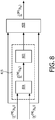
- the designator 415 of FIG. 4 may comprise a difference unit 801 which calculates a difference value for the time frequency tile by evaluating the distance measure assuming that the time frequency tile is indeed a noise tile.
- the resulting difference value is fed to a tile designator 803 which proceeds to designate the tile as being a noise tile if the distance value is below a given threshold, and as a speech tile otherwise.
- the approach provides for a very efficient and accurate detection and designation of tiles as speech or noise tiles. Furthermore, facilitated implementation and operation is achieved by re-using functionality for calculating the gains as part of the designator. For example, for all time frequency tiles that are designated as noise tiles, the calculated difference measure can directly be used to determine the gain. A recalculation of the difference measure is only required by the gain unit 409 for time frequency tiles that are designated as speech tiles.
- a low pass filtering/smoothing may be included in the designation based on the difference values.
- the filtering may specifically be across different time frequency tiles in both the frequency and time domain.
- filtering may be performed over time frequency tile difference values belonging to different (neighboring) time segments/ frames as well as over multiple time frequency tiles in at least one of the time segments.
- the inventors have realized that such filtering may provide substantial performance improvements and a substantially improved designation and accordingly may provide a substantially improved noise suppression.
- a low pass filtering/smoothing may be included in the gain calculation.
- the filtering may specifically be across different time frequency tiles in both the frequency and time domain.
- filtering may be performed over time frequency tile values belonging to different (neighboring) time segments/ frames as well as over multiple time frequency tiles in at least one of the time segments.
- the inventors have realized that such filtering may provide substantial performance improvements and a substantially improved perceived noise suppression.
- the smoothing (i.e. the low pass filtering) may specifically be applied to the calculated gain values.
- the filtering may be applied to the first and second frequency domain signals prior to the gain calculation.
- the filtering may be applied to parameters of the gain calculation, such as to the difference measures.
- the gain unit 409 may be arranged to filter gain values over a plurality of time frequency tiles where the filtering includes time frequency tiles differing in both time and frequency.
- G ( t k , ⁇ l ) are calculated as a monotonic function of the difference measure but is not restricted to non-negative values. Indeed, the non-clipped gain may have negative values for the difference measure being negative.
- the gain unit may be arranged to filter at least one of the magnitude time frequency tile values of the first frequency domain signal and the magnitude time frequency tile values of the second frequency domain signal prior to these being used for calculating the gain values.
- the filtering is performed on the input to the gain calculation rather than at the output.
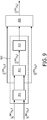
- FIG. 9 An example of this approach is illustrated in FIG. 9 .
- the example corresponds to that of FIG. 8 but with the addition of a low pass filter 901 which performs a low pass filtering of the magnitudes of the time frequency tile values of the first and second frequency domain signal.
- are filtered to provide the smoothed vectors
- G t k , ⁇ l M A X
- ⁇ , ⁇ , and G t k , ⁇ l M A X
- the filtering may specifically use a uniform window like a rectangular window in time and frequency, or a window that is based on the characteristics of human hearing. In the latter case, the filtering may specifically be according to so-called critical bands.
- the critical band refers to the frequency bandwidth of the "auditory filter" created by the cochlea. For example octave bands or bark scale critical bands may be used.
- the filtering may be frequency dependent. Specifically, at low frequencies, the averaging may be over only a few frequency bins, whereas more frequency bins may be used at higher frequencies.
- the smoothing/ filtering may be performed by averaging over neighboring values, such as e.g.:
- n ⁇ 1 N
- N can also be dependent on the critical band and can then depend on the frequency index 1. For higher frequencies, N will typically be larger than for lower frequencies.
- the filtering may be by filtering the difference measure, such as e.g. by calculating it as
- the filtering/ smoothing may provide substantial performance improvements.
- the rows indicate different oversubtraction factors (with values given in the first column) and the columns indicate different averaging areas (with the number of tiles averaged over being presented in the first row): 1 2 3 4 5 9 25 1.0 6.7 9.7 11.5 12.7 13.7 16.3 20.7 1.2 7.8 11.5 13.9 15.7 17.1 21.3 30.4 1.4 8.8 13.3 16.3 18.6 20.6 26.6 42.0 1.6 9.7 14.9 18.6 21.5 24.0 32.1 54.6 1.8 10.6 16.5 20.7 24.3 27.2 37.6 68.0 2.0 11.4 17.9 22.8 26.9 30.5 42.8 82.9 4.0 17.0 28.6 24.7 46.9 55.8 47.8 >100.0
- the values K 1 to K8, or at least the total number of time frequency tile values being summed in each summation may be identical.
- the corresponding functions f a (x) and f b (x) may include a compensation for the differing number of values.
- the functions f a (x) and f b (x) may in some embodiments including a weighting of the value in the summation, i.e. they may be dependent on summation index.
- the time frequency tile values of both the first and second frequency domain signals are averaged/ filtered over a neighborhood of the current tile.
- f 1 (x) or f 2 (x) may further be dependent on a noise coherence estimate which is indicative of an average difference between noise levels of the first microphone signal and the second microphone signal.
- One or both of the functions f 1 (x) or f 2 (x) may specifically include a scaling by a scale factor which reflects an estimated average noise level difference between the first and second microphone signal.
- One or both of the functions f 1 (x) or f 2 (x) may specifically be dependent on the previously mentioned coherence term C ( t k , ⁇ l ) .
- the functions f 1 (x) and f 2 (x) may simply be a scaling of the magnitude values.
- a particular advantage of such an approach is that a difference measure based on a magnitude based subtraction may take on both positive and negative values when only noise is present.
- This is particularly suitable for averaging/ smoothing/ filtering where variations around e.g. a zero mean will tend to cancel each other.
- when speech is present, this will predominantly only be in the first microphone signal, i.e. it will predominantly be present in
- a smoothing or filtering over e.g. neighboring time frequency tiles will tend to reduce the noise contribution in the difference measure but not the speech component.
- a particularly advantageous synergistic effect can be achieved by the combination of the averaging and the difference magnitude based difference measure.
- microphones are often placed much closer together and consequently two effects may become more significant, namely that both microphones may begin to capture an element of the desired speech, and that the coherence between the microphone signals at low frequencies cannot be neglected.
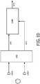
- the noise suppressor may further comprise an audio beamformer which is arranged to generate the first microphone signal and the second microphone signal from signals from a microphone array. An example of this is illustrated in FIG. 10 .
- the microphone array may in some embodiments comprise only two microphones but will typically comprise a higher number.
- the beamformer depicted as a BMF unit, may generate a plurality of different beams directed in different directions, and the different beams may each generate one of the first and second microphone signals.
- the beamformer may specifically be an adaptive beamformer in which one beam can be directed towards the speech source using a suitable adaptation algorithm. At the same time, the other beam can be adapted to generate a notch (or specifically a null) in the direction of the speech source.
- US 7 146 012 and US 7 602 926 discloses examples of adaptive beamformers that focus on the speech but also provides a reference signal that contains (almost) no speech. Such an approach may be used to generate the first microphone signal as the primary output of the beamformer and the second first microphone signal as the secondary output of the beam former.
- Noise components will be available in both beamformer signals and will still be Gaussian distributed for diffuse noise.
- the coherence function between the noise components in z(n) and x(n) will still be dependent on sinc(kd) as previously described, i.e. at higher frequencies the coherence will be approximately zero and the noise suppressor of FIG. 4 can be used effectively.
- the noise suppressor may further comprise an adaptive canceller for cancelling a signal component of the first microphone signal correlated with the second microphone signal from the first microphone signal.
- FIG. 11 An example of a noise suppressor with both the suppressor of FIG. 4 , the beamformer of FIG. 10 , and an adaptive canceller is illustrated in FIG. 11 .
- the adaptive canceller implements an extra adaptive noise cancellation algorithm that removes the noise in z(n) which is correlated with the noise in x(n).
- the coherence between x(n) and the residual signal r(n) will be zero.
- the invention can be implemented in any suitable form including hardware, software, firmware or any combination of these.
- the invention may optionally be implemented at least partly as computer software running on one or more data processors and/or digital signal processors.
- the elements and components of an embodiment of the invention may be physically, functionally and logically implemented in any suitable way. Indeed the functionality may be implemented in a single unit, in a plurality of units or as part of other functional units. As such, the invention may be implemented in a single unit or may be physically and functionally distributed between different units, circuits and processors.
Landscapes
- Engineering & Computer Science (AREA)
- Physics & Mathematics (AREA)
- Acoustics & Sound (AREA)
- Health & Medical Sciences (AREA)
- Signal Processing (AREA)
- Multimedia (AREA)
- Audiology, Speech & Language Pathology (AREA)
- Human Computer Interaction (AREA)
- Computational Linguistics (AREA)
- Quality & Reliability (AREA)
- Spectroscopy & Molecular Physics (AREA)
- General Health & Medical Sciences (AREA)
- Otolaryngology (AREA)
- Circuit For Audible Band Transducer (AREA)
- Obtaining Desirable Characteristics In Audible-Bandwidth Transducers (AREA)
- Soundproofing, Sound Blocking, And Sound Damping (AREA)
- Fittings On The Vehicle Exterior For Carrying Loads, And Devices For Holding Or Mounting Articles (AREA)
Claims (14)
- Dispositif suppresseur de bruit pour supprimer du bruit dans un premier signal de microphone, le dispositif suppresseur de bruit comprenant :un premier transformateur (401) pour produire un premier signal de domaine fréquentiel à partir d'une transformée de fréquence d'un premier signal de microphone, le premier signal de domaine fréquentiel étant représenté par des valeurs de pavés de temps-fréquence ;un second transformateur (403) pour produire un second signal de domaine fréquentiel à partir d'une transformée de fréquence d'un second signal de microphone, le second signal de domaine fréquentiel étant représenté par des valeurs de pavés de temps-fréquence ;une unité de gain (405, 407, 409) pour déterminer des gains de pavé de temps-fréquence en tant que fonction monotone non négative d'une mesure de différence qui est indicative d'une différence entre une première fonction monotone d'une valeur de pavé de temps-fréquence d'amplitude du premier signal de domaine fréquentiel et une seconde fonction monotone d'une valeur de pavé de temps-fréquence d'amplitude du second signal de domaine fréquentiel ; etun dispositif de mise à l'échelle (411) pour produire un signal de domaine fréquentiel de sortie en mettant à l'échelle des valeurs de pavés de temps-fréquence du premier signal de domaine fréquentiel par les gains de pavé de temps-fréquence ;le dispositif suppresseur de bruit comprenant en outre :un indicateur (405, 407, 415) pour désigner des pavés de temps-fréquence du premier signal de domaine fréquentiel en tant que pavés de parole ou pavés de bruit ; etl'unité de gain (405, 407, 409) est agencée pour déterminer les gains de pavé de temps-fréquence en réponse à la désignation des pavés de temps-fréquence du premier signal de domaine fréquentiel en tant que pavés de parole ou pavés de bruit de sorte qu'une valeur de gain inférieure pour un gain de pavé de temps-fréquence d'un pavé de temps-fréquence est déterminé quand le pavé de temps-fréquence est désigné comme un pavé de bruit que lorsque le pavé de temps-fréquence est désigné comme un pavé de parole.
- Dispositif suppresseur de bruit selon la revendication 1, dans lequel au moins une de la première fonction monotone et de la seconde fonction monotone dépend du fait que le pavé de temps-fréquence est désigné comme un pavé de parole ou comme un pavé de bruit.
- Dispositif suppresseur de bruit selon la revendication 2, dans lequel la seconde fonction monotone comprend une mise à l'échelle de la valeur de pavé de temps-fréquence d'amplitude du second signal de domaine fréquentiel pour le pavé de temps-fréquence avec une valeur d'échelle dépendant du fait que le pavé de temps-fréquence est désigné comme un pavé de temps-fréquence de parole ou un pavé de temps-fréquence de bruit.
- Dispositif suppresseur de bruit selon la revendication 2, dans lequel l'unité de gain (405, 407, 409) est agencée pour produire une évaluation de cohérence de bruit indicative d'une corrélation entre une amplitude du second signal de microphone et une amplitude d'une composante de bruit du premier signal de microphone et au moins une de la première fonction monotone et de la seconde fonction monotone dépend de l'évaluation de cohérence de bruit.
- Dispositif suppresseur de bruit selon la revendication 4, dans lequel la première fonction monotone et la seconde fonction monotone sont telles qu'une valeur attendue de la mesure de différence est négative quand le pavé de temps-fréquence est désigné comme un pavé de bruit.
- Dispositif suppresseur de bruit selon la revendication 5, dans lequel l'unité de gain (405, 407, 409) est agencée pour faire varier au moins une de la première fonction monotone et de la seconde fonction monotone de sorte que la valeur attendue de la mesure de différence pour la relation d'amplitude entre le premier signal de microphone et le second signal de microphone correspondant à l'évaluation de cohérence de bruit est différente pour un pavé de temps-fréquence désigné comme un pavé de bruit que pour un pavé de temps-fréquence désigné comme un pavé de parole.
- Dispositif suppresseur de bruit selon la revendication 1, dans lequel l'indicateur (405, 407, 415) est agencé pour désigner des pavés de temps-fréquence du premier signal de domaine fréquentiel en tant que pavés de parole ou pavés de bruit en réponse à des valeurs de différence produites en calculant la mesure de différence en supposant que le pavé de temps-fréquence est un pavé de bruit.
- Dispositif suppresseur de bruit selon la revendication 7, dans lequel l'indicateur (405, 407, 415) est agencé pour filtrer des valeurs de différence sur une pluralité de pavés de temps-fréquence, le filtrage incluant des pavés de temps-fréquence différant tant pour le temps que pour la fréquence.
- Dispositif suppresseur de bruit selon la revendication 1, dans lequel l'unité de gain (405, 407, 409) est agencée pour filtrer des valeurs de gain sur une pluralité de pavés de temps-fréquence, le filtrage incluant des pavés de temps-fréquence différant tant pour le temps que pour la fréquence.
- Dispositif suppresseur de bruit selon la revendication 1, dans lequel l'unité de gain (405, 407, 409) est agencée pour filtrer au moins une des valeurs de pavé de temps-fréquence d'amplitude du premier signal de domaine fréquentiel et des valeurs de pavé de temps-fréquence d'amplitude du second signal de domaine fréquentiel ; le filtrage incluant des pavés de temps-fréquence différant tant pour le temps que pour la fréquence.
- Dispositif suppresseur de bruit selon la revendication 1, comprenant en outre un dispositif de formation de faisceau audio agencé pour produire le premier signal de microphone et le second signal de microphone à partir de signaux provenant d'un réseau de microphones.
- Dispositif suppresseur de bruit selon la revendication 1, comprenant en outre un dispositif d'annulation adaptatif pour annuler une composante de signal du premier signal de microphone corrélé au second signal de microphone à partir du premier signal de microphone.
- Procédé de suppression de bruit dans un premier signal de microphone, le procédé comprenant :la production d'un premier signal de domaine fréquentiel à partir d'une transformée de fréquence d'un premier signal de microphone, le premier signal de domaine fréquentiel étant représenté par des valeurs de pavés de temps-fréquence ;la production d'un second signal de domaine fréquentiel à partir d'une transformée de fréquence d'un second signal de microphone, le second signal de domaine fréquentiel étant représenté par des valeurs de pavés de temps-fréquence ;la détermination de gains de pavé de temps-fréquence comme une fonction monotone non négative d'une mesure de différence qui est indicative d'une différence entre une première fonction monotone d'une valeur de pavé de temps-fréquence d'amplitude du premier signal de domaine fréquentiel et une seconde fonction monotone d'une valeur de pavé de temps-fréquence d'amplitude du second signal de domaine fréquentiel ; etla production d'un signal de domaine fréquentiel de sortie en mettant à l'échelle des valeurs de pavé de temps-fréquence du premier signal de domaine fréquentiel par les gains de pavé de temps-fréquence ;le procédé comprenant en outre :
la désignation de pavés de temps-fréquence du premier signal de domaine fréquentiel en tant que pavés de parole ou pavés de bruit ; et dans lequel les gains de pavé de temps-fréquence sont déterminés en réponse à la désignation des pavés de temps-fréquence du premier signal de domaine fréquentiel en tant que pavés de parole ou pavés de bruit de sorte qu'une valeur de gain inférieure pour un gain de pavé de temps-fréquence d'un pavé de temps-fréquence est déterminée quand le pavé de temps-fréquence est désigné comme un pavé de bruit que lorsque le pavé de temps-fréquence est désigné comme un pavé de parole. - Produit formant programme informatique comprenant un moyen formant code de programme informatique conçu pour effectuer toutes les étapes de la revendication 13 lorsque ledit programme est exécuté sur un ordinateur.
Applications Claiming Priority (2)
| Application Number | Priority Date | Filing Date | Title |
|---|---|---|---|
| EP14160242 | 2014-03-17 | ||
| PCT/EP2015/054228 WO2015139938A2 (fr) | 2014-03-17 | 2015-03-02 | Suppression de bruit |
Publications (2)
| Publication Number | Publication Date |
|---|---|
| EP3120355A2 EP3120355A2 (fr) | 2017-01-25 |
| EP3120355B1 true EP3120355B1 (fr) | 2018-08-29 |
Family
ID=50280267
Family Applications (1)
| Application Number | Title | Priority Date | Filing Date |
|---|---|---|---|
| EP15707356.0A Active EP3120355B1 (fr) | 2014-03-17 | 2015-03-02 | Suppression de bruit |
Country Status (6)
| Country | Link |
|---|---|
| US (1) | US10026415B2 (fr) |
| EP (1) | EP3120355B1 (fr) |
| JP (1) | JP6134078B1 (fr) |
| CN (1) | CN106068535B (fr) |
| TR (1) | TR201815883T4 (fr) |
| WO (1) | WO2015139938A2 (fr) |
Families Citing this family (20)
| Publication number | Priority date | Publication date | Assignee | Title |
|---|---|---|---|---|
| US10332541B2 (en) * | 2014-11-12 | 2019-06-25 | Cirrus Logic, Inc. | Determining noise and sound power level differences between primary and reference channels |
| CN106997768B (zh) * | 2016-01-25 | 2019-12-10 | 电信科学技术研究院 | 一种语音出现概率的计算方法、装置及电子设备 |
| GB2549922A (en) * | 2016-01-27 | 2017-11-08 | Nokia Technologies Oy | Apparatus, methods and computer computer programs for encoding and decoding audio signals |
| JP6693340B2 (ja) * | 2016-08-30 | 2020-05-13 | 富士通株式会社 | 音声処理プログラム、音声処理装置、及び音声処理方法 |
| GB201615538D0 (en) * | 2016-09-13 | 2016-10-26 | Nokia Technologies Oy | A method , apparatus and computer program for processing audio signals |
| US9906859B1 (en) * | 2016-09-30 | 2018-02-27 | Bose Corporation | Noise estimation for dynamic sound adjustment |
| CN110140360B (zh) * | 2017-01-03 | 2021-07-16 | 皇家飞利浦有限公司 | 使用波束形成的音频捕获的方法和装置 |
| WO2018127450A1 (fr) | 2017-01-03 | 2018-07-12 | Koninklijke Philips N.V. | Capture audio à l'aide d'une formation de faisceaux |
| JP6665353B2 (ja) | 2017-01-03 | 2020-03-13 | コーニンクレッカ フィリップス エヌ ヴェKoninklijke Philips N.V. | ビームフォーミングを使用するオーディオキャプチャ |
| RU2759715C2 (ru) * | 2017-01-03 | 2021-11-17 | Конинклейке Филипс Н.В. | Звукозапись с использованием формирования диаграммы направленности |
| EP3905718B1 (fr) * | 2017-03-24 | 2024-03-13 | Yamaha Corporation | Dispositif et procédé de capture de son |
| US10043531B1 (en) * | 2018-02-08 | 2018-08-07 | Omnivision Technologies, Inc. | Method and audio noise suppressor using MinMax follower to estimate noise |
| US10043530B1 (en) * | 2018-02-08 | 2018-08-07 | Omnivision Technologies, Inc. | Method and audio noise suppressor using nonlinear gain smoothing for reduced musical artifacts |
| CN111684213A (zh) * | 2018-10-22 | 2020-09-18 | 深圳配天智能技术研究院有限公司 | 机器人故障诊断方法、系统及存储装置 |
| GB2580057A (en) * | 2018-12-20 | 2020-07-15 | Nokia Technologies Oy | Apparatus, methods and computer programs for controlling noise reduction |
| US11195540B2 (en) * | 2019-01-28 | 2021-12-07 | Cirrus Logic, Inc. | Methods and apparatus for an adaptive blocking matrix |
| CN111028841B (zh) * | 2020-03-10 | 2020-07-07 | 深圳市友杰智新科技有限公司 | 唤醒系统调节参数的方法、装置、计算机设备和存储介质 |
| EP4288961A1 (fr) * | 2021-02-04 | 2023-12-13 | Neatframe Limited | Traitement audio |
| CN113160846B (zh) * | 2021-04-22 | 2024-05-17 | 维沃移动通信有限公司 | 噪声抑制方法和电子设备 |
| US11889261B2 (en) * | 2021-10-06 | 2024-01-30 | Bose Corporation | Adaptive beamformer for enhanced far-field sound pickup |
Family Cites Families (12)
| Publication number | Priority date | Publication date | Assignee | Title |
|---|---|---|---|---|
| JP3361724B2 (ja) * | 1997-06-11 | 2003-01-07 | 沖電気工業株式会社 | エコーキャンセラ装置 |
| US7146012B1 (en) | 1997-11-22 | 2006-12-05 | Koninklijke Philips Electronics N.V. | Audio processing arrangement with multiple sources |
| US6122610A (en) * | 1998-09-23 | 2000-09-19 | Verance Corporation | Noise suppression for low bitrate speech coder |
| WO2004004297A2 (fr) | 2002-07-01 | 2004-01-08 | Koninklijke Philips Electronics N.V. | Systeme d'optimisation audio en fonction de l'energie spectrale fixe |
| US7587056B2 (en) * | 2006-09-14 | 2009-09-08 | Fortemedia, Inc. | Small array microphone apparatus and noise suppression methods thereof |
| JP4519901B2 (ja) * | 2007-04-26 | 2010-08-04 | 株式会社神戸製鋼所 | 目的音抽出装置,目的音抽出プログラム,目的音抽出方法 |
| JP4649546B2 (ja) * | 2009-02-09 | 2011-03-09 | パナソニック株式会社 | 補聴器 |
| FR2976710B1 (fr) * | 2011-06-20 | 2013-07-05 | Parrot | Procede de debruitage pour equipement audio multi-microphones, notamment pour un systeme de telephonie "mains libres" |
| US8239196B1 (en) * | 2011-07-28 | 2012-08-07 | Google Inc. | System and method for multi-channel multi-feature speech/noise classification for noise suppression |
| US9666206B2 (en) * | 2011-08-24 | 2017-05-30 | Texas Instruments Incorporated | Method, system and computer program product for attenuating noise in multiple time frames |
| US9173025B2 (en) * | 2012-02-08 | 2015-10-27 | Dolby Laboratories Licensing Corporation | Combined suppression of noise, echo, and out-of-location signals |
| EP3155618B1 (fr) * | 2014-06-13 | 2022-05-11 | Oticon A/S | Système de réduction de bruit multibande et méthodologie pour des signaux audio-numériques |
-
2015
- 2015-03-02 CN CN201580014247.1A patent/CN106068535B/zh active Active
- 2015-03-02 JP JP2016557303A patent/JP6134078B1/ja active Active
- 2015-03-02 EP EP15707356.0A patent/EP3120355B1/fr active Active
- 2015-03-02 WO PCT/EP2015/054228 patent/WO2015139938A2/fr not_active Ceased
- 2015-03-02 TR TR2018/15883T patent/TR201815883T4/tr unknown
- 2015-03-02 US US15/120,130 patent/US10026415B2/en active Active
Also Published As
| Publication number | Publication date |
|---|---|
| CN106068535B (zh) | 2019-11-05 |
| EP3120355A2 (fr) | 2017-01-25 |
| WO2015139938A3 (fr) | 2015-11-26 |
| WO2015139938A2 (fr) | 2015-09-24 |
| US10026415B2 (en) | 2018-07-17 |
| CN106068535A (zh) | 2016-11-02 |
| TR201815883T4 (tr) | 2018-11-21 |
| US20180122399A1 (en) | 2018-05-03 |
| JP2017516126A (ja) | 2017-06-15 |
| JP6134078B1 (ja) | 2017-05-24 |
Similar Documents
| Publication | Publication Date | Title |
|---|---|---|
| EP3120355B1 (fr) | Suppression de bruit | |
| US8654990B2 (en) | Multiple microphone based directional sound filter | |
| JP5762956B2 (ja) | ヌル処理雑音除去を利用した雑音抑制を提供するシステム及び方法 | |
| US10771894B2 (en) | Method and apparatus for audio capture using beamforming | |
| EP1592282B1 (fr) | Procédé et système de téléconférence | |
| US9437180B2 (en) | Adaptive noise reduction using level cues | |
| US10979100B2 (en) | Audio signal processing with acoustic echo cancellation | |
| EP2647221B1 (fr) | Appareil et procédé d'acquisition sonore spatialement sélective par triangulation acoustique | |
| Kodrasi et al. | Joint dereverberation and noise reduction based on acoustic multi-channel equalization | |
| EP3566463B1 (fr) | Prise de son audio au moyen d'une formation de faisceau | |
| EP1131892B1 (fr) | Appareil et procede de traitement de signaux | |
| EP2254113A1 (fr) | Appareil et programme de suppression de bruit | |
| EP3275208B1 (fr) | Mélange de sous-bande de multiples microphones | |
| EP2681932A1 (fr) | Appareil et procédé pour déterminer une mesure d'un niveau de réverbération perçu, processeur audio et procédé de traitement d'un signal | |
| US11380312B1 (en) | Residual echo suppression for keyword detection | |
| DK3008924T3 (en) | METHOD OF SIGNAL PROCESSING IN A HEARING SYSTEM AND HEARING SYSTEM | |
| GB2453118A (en) | Generating a speech audio signal from multiple microphones with suppressed wind noise | |
| Kim | Hearing aid speech enhancement using phase difference-controlled dual-microphone generalized sidelobe canceller | |
| US20190035382A1 (en) | Adaptive post filtering | |
| EP3566228B1 (fr) | Capture audio au moyen de formation de faisceau | |
| EP3531719B1 (fr) | Dispositif de déréverbération et prothèse auditive | |
| Pfeifenberger et al. | A multi-channel postfilter based on the diffuse noise sound field | |
| Martin et al. | Binaural speech enhancement with instantaneous coherence smoothing using the cepstral correlation coefficient | |
| Zhang et al. | A frequency domain approach for speech enhancement with directionality using compact microphone array. | |
| Naghibi et al. | An approach to prevent adaptive beamformers from cancelling the desired signal |
Legal Events
| Date | Code | Title | Description |
|---|---|---|---|
| STAA | Information on the status of an ep patent application or granted ep patent |
Free format text: STATUS: THE INTERNATIONAL PUBLICATION HAS BEEN MADE |
|
| PUAI | Public reference made under article 153(3) epc to a published international application that has entered the european phase |
Free format text: ORIGINAL CODE: 0009012 |
|
| STAA | Information on the status of an ep patent application or granted ep patent |
Free format text: STATUS: REQUEST FOR EXAMINATION WAS MADE |
|
| 17P | Request for examination filed |
Effective date: 20161017 |
|
| AK | Designated contracting states |
Kind code of ref document: A2 Designated state(s): AL AT BE BG CH CY CZ DE DK EE ES FI FR GB GR HR HU IE IS IT LI LT LU LV MC MK MT NL NO PL PT RO RS SE SI SK SM TR |
|
| AX | Request for extension of the european patent |
Extension state: BA ME |
|
| STAA | Information on the status of an ep patent application or granted ep patent |
Free format text: STATUS: EXAMINATION IS IN PROGRESS |
|
| 17Q | First examination report despatched |
Effective date: 20170420 |
|
| DAV | Request for validation of the european patent (deleted) | ||
| DAX | Request for extension of the european patent (deleted) | ||
| GRAP | Despatch of communication of intention to grant a patent |
Free format text: ORIGINAL CODE: EPIDOSNIGR1 |
|
| STAA | Information on the status of an ep patent application or granted ep patent |
Free format text: STATUS: GRANT OF PATENT IS INTENDED |
|
| RIC1 | Information provided on ipc code assigned before grant |
Ipc: G10L 25/18 20130101ALI20180222BHEP Ipc: G10L 21/0216 20130101ALN20180222BHEP Ipc: G10L 21/0208 20130101AFI20180222BHEP |
|
| INTG | Intention to grant announced |
Effective date: 20180323 |
|
| GRAS | Grant fee paid |
Free format text: ORIGINAL CODE: EPIDOSNIGR3 |
|
| GRAA | (expected) grant |
Free format text: ORIGINAL CODE: 0009210 |
|
| STAA | Information on the status of an ep patent application or granted ep patent |
Free format text: STATUS: THE PATENT HAS BEEN GRANTED |
|
| AK | Designated contracting states |
Kind code of ref document: B1 Designated state(s): AL AT BE BG CH CY CZ DE DK EE ES FI FR GB GR HR HU IE IS IT LI LT LU LV MC MK MT NL NO PL PT RO RS SE SI SK SM TR |
|
| REG | Reference to a national code |
Ref country code: GB Ref legal event code: FG4D |
|
| REG | Reference to a national code |
Ref country code: CH Ref legal event code: EP |
|
| REG | Reference to a national code |
Ref country code: AT Ref legal event code: REF Ref document number: 1036099 Country of ref document: AT Kind code of ref document: T Effective date: 20180915 |
|
| REG | Reference to a national code |
Ref country code: IE Ref legal event code: FG4D |
|
| REG | Reference to a national code |
Ref country code: DE Ref legal event code: R096 Ref document number: 602015015499 Country of ref document: DE |
|
| REG | Reference to a national code |
Ref country code: NL Ref legal event code: MP Effective date: 20180829 |
|
| REG | Reference to a national code |
Ref country code: LT Ref legal event code: MG4D |
|
| PG25 | Lapsed in a contracting state [announced via postgrant information from national office to epo] |
Ref country code: GR Free format text: LAPSE BECAUSE OF FAILURE TO SUBMIT A TRANSLATION OF THE DESCRIPTION OR TO PAY THE FEE WITHIN THE PRESCRIBED TIME-LIMIT Effective date: 20181130 Ref country code: RS Free format text: LAPSE BECAUSE OF FAILURE TO SUBMIT A TRANSLATION OF THE DESCRIPTION OR TO PAY THE FEE WITHIN THE PRESCRIBED TIME-LIMIT Effective date: 20180829 Ref country code: FI Free format text: LAPSE BECAUSE OF FAILURE TO SUBMIT A TRANSLATION OF THE DESCRIPTION OR TO PAY THE FEE WITHIN THE PRESCRIBED TIME-LIMIT Effective date: 20180829 Ref country code: LT Free format text: LAPSE BECAUSE OF FAILURE TO SUBMIT A TRANSLATION OF THE DESCRIPTION OR TO PAY THE FEE WITHIN THE PRESCRIBED TIME-LIMIT Effective date: 20180829 Ref country code: SE Free format text: LAPSE BECAUSE OF FAILURE TO SUBMIT A TRANSLATION OF THE DESCRIPTION OR TO PAY THE FEE WITHIN THE PRESCRIBED TIME-LIMIT Effective date: 20180829 Ref country code: NO Free format text: LAPSE BECAUSE OF FAILURE TO SUBMIT A TRANSLATION OF THE DESCRIPTION OR TO PAY THE FEE WITHIN THE PRESCRIBED TIME-LIMIT Effective date: 20181129 Ref country code: NL Free format text: LAPSE BECAUSE OF FAILURE TO SUBMIT A TRANSLATION OF THE DESCRIPTION OR TO PAY THE FEE WITHIN THE PRESCRIBED TIME-LIMIT Effective date: 20180829 Ref country code: IS Free format text: LAPSE BECAUSE OF FAILURE TO SUBMIT A TRANSLATION OF THE DESCRIPTION OR TO PAY THE FEE WITHIN THE PRESCRIBED TIME-LIMIT Effective date: 20181229 Ref country code: BG Free format text: LAPSE BECAUSE OF FAILURE TO SUBMIT A TRANSLATION OF THE DESCRIPTION OR TO PAY THE FEE WITHIN THE PRESCRIBED TIME-LIMIT Effective date: 20181129 |
|
| REG | Reference to a national code |
Ref country code: AT Ref legal event code: MK05 Ref document number: 1036099 Country of ref document: AT Kind code of ref document: T Effective date: 20180829 |
|
| PG25 | Lapsed in a contracting state [announced via postgrant information from national office to epo] |
Ref country code: HR Free format text: LAPSE BECAUSE OF FAILURE TO SUBMIT A TRANSLATION OF THE DESCRIPTION OR TO PAY THE FEE WITHIN THE PRESCRIBED TIME-LIMIT Effective date: 20180829 Ref country code: AL Free format text: LAPSE BECAUSE OF FAILURE TO SUBMIT A TRANSLATION OF THE DESCRIPTION OR TO PAY THE FEE WITHIN THE PRESCRIBED TIME-LIMIT Effective date: 20180829 Ref country code: LV Free format text: LAPSE BECAUSE OF FAILURE TO SUBMIT A TRANSLATION OF THE DESCRIPTION OR TO PAY THE FEE WITHIN THE PRESCRIBED TIME-LIMIT Effective date: 20180829 |
|
| PG25 | Lapsed in a contracting state [announced via postgrant information from national office to epo] |
Ref country code: ES Free format text: LAPSE BECAUSE OF FAILURE TO SUBMIT A TRANSLATION OF THE DESCRIPTION OR TO PAY THE FEE WITHIN THE PRESCRIBED TIME-LIMIT Effective date: 20180829 Ref country code: RO Free format text: LAPSE BECAUSE OF FAILURE TO SUBMIT A TRANSLATION OF THE DESCRIPTION OR TO PAY THE FEE WITHIN THE PRESCRIBED TIME-LIMIT Effective date: 20180829 Ref country code: IT Free format text: LAPSE BECAUSE OF FAILURE TO SUBMIT A TRANSLATION OF THE DESCRIPTION OR TO PAY THE FEE WITHIN THE PRESCRIBED TIME-LIMIT Effective date: 20180829 Ref country code: AT Free format text: LAPSE BECAUSE OF FAILURE TO SUBMIT A TRANSLATION OF THE DESCRIPTION OR TO PAY THE FEE WITHIN THE PRESCRIBED TIME-LIMIT Effective date: 20180829 Ref country code: CZ Free format text: LAPSE BECAUSE OF FAILURE TO SUBMIT A TRANSLATION OF THE DESCRIPTION OR TO PAY THE FEE WITHIN THE PRESCRIBED TIME-LIMIT Effective date: 20180829 Ref country code: EE Free format text: LAPSE BECAUSE OF FAILURE TO SUBMIT A TRANSLATION OF THE DESCRIPTION OR TO PAY THE FEE WITHIN THE PRESCRIBED TIME-LIMIT Effective date: 20180829 Ref country code: PL Free format text: LAPSE BECAUSE OF FAILURE TO SUBMIT A TRANSLATION OF THE DESCRIPTION OR TO PAY THE FEE WITHIN THE PRESCRIBED TIME-LIMIT Effective date: 20180829 |
|
| PG25 | Lapsed in a contracting state [announced via postgrant information from national office to epo] |
Ref country code: DK Free format text: LAPSE BECAUSE OF FAILURE TO SUBMIT A TRANSLATION OF THE DESCRIPTION OR TO PAY THE FEE WITHIN THE PRESCRIBED TIME-LIMIT Effective date: 20180829 Ref country code: SK Free format text: LAPSE BECAUSE OF FAILURE TO SUBMIT A TRANSLATION OF THE DESCRIPTION OR TO PAY THE FEE WITHIN THE PRESCRIBED TIME-LIMIT Effective date: 20180829 Ref country code: SM Free format text: LAPSE BECAUSE OF FAILURE TO SUBMIT A TRANSLATION OF THE DESCRIPTION OR TO PAY THE FEE WITHIN THE PRESCRIBED TIME-LIMIT Effective date: 20180829 |
|
| REG | Reference to a national code |
Ref country code: DE Ref legal event code: R097 Ref document number: 602015015499 Country of ref document: DE |
|
| PLBE | No opposition filed within time limit |
Free format text: ORIGINAL CODE: 0009261 |
|
| STAA | Information on the status of an ep patent application or granted ep patent |
Free format text: STATUS: NO OPPOSITION FILED WITHIN TIME LIMIT |
|
| 26N | No opposition filed |
Effective date: 20190531 |
|
| PG25 | Lapsed in a contracting state [announced via postgrant information from national office to epo] |
Ref country code: SI Free format text: LAPSE BECAUSE OF FAILURE TO SUBMIT A TRANSLATION OF THE DESCRIPTION OR TO PAY THE FEE WITHIN THE PRESCRIBED TIME-LIMIT Effective date: 20180829 |
|
| PG25 | Lapsed in a contracting state [announced via postgrant information from national office to epo] |
Ref country code: MC Free format text: LAPSE BECAUSE OF FAILURE TO SUBMIT A TRANSLATION OF THE DESCRIPTION OR TO PAY THE FEE WITHIN THE PRESCRIBED TIME-LIMIT Effective date: 20180829 |
|
| REG | Reference to a national code |
Ref country code: CH Ref legal event code: PL |
|
| PG25 | Lapsed in a contracting state [announced via postgrant information from national office to epo] |
Ref country code: LU Free format text: LAPSE BECAUSE OF NON-PAYMENT OF DUE FEES Effective date: 20190302 |
|
| REG | Reference to a national code |
Ref country code: BE Ref legal event code: MM Effective date: 20190331 |
|
| PG25 | Lapsed in a contracting state [announced via postgrant information from national office to epo] |
Ref country code: IE Free format text: LAPSE BECAUSE OF NON-PAYMENT OF DUE FEES Effective date: 20190302 Ref country code: CH Free format text: LAPSE BECAUSE OF NON-PAYMENT OF DUE FEES Effective date: 20190331 Ref country code: LI Free format text: LAPSE BECAUSE OF NON-PAYMENT OF DUE FEES Effective date: 20190331 |
|
| PG25 | Lapsed in a contracting state [announced via postgrant information from national office to epo] |
Ref country code: BE Free format text: LAPSE BECAUSE OF NON-PAYMENT OF DUE FEES Effective date: 20190331 |
|
| PG25 | Lapsed in a contracting state [announced via postgrant information from national office to epo] |
Ref country code: MT Free format text: LAPSE BECAUSE OF NON-PAYMENT OF DUE FEES Effective date: 20190302 Ref country code: PT Free format text: LAPSE BECAUSE OF FAILURE TO SUBMIT A TRANSLATION OF THE DESCRIPTION OR TO PAY THE FEE WITHIN THE PRESCRIBED TIME-LIMIT Effective date: 20181229 |
|
| PG25 | Lapsed in a contracting state [announced via postgrant information from national office to epo] |
Ref country code: CY Free format text: LAPSE BECAUSE OF FAILURE TO SUBMIT A TRANSLATION OF THE DESCRIPTION OR TO PAY THE FEE WITHIN THE PRESCRIBED TIME-LIMIT Effective date: 20180829 |
|
| PG25 | Lapsed in a contracting state [announced via postgrant information from national office to epo] |
Ref country code: HU Free format text: LAPSE BECAUSE OF FAILURE TO SUBMIT A TRANSLATION OF THE DESCRIPTION OR TO PAY THE FEE WITHIN THE PRESCRIBED TIME-LIMIT; INVALID AB INITIO Effective date: 20150302 |
|
| PG25 | Lapsed in a contracting state [announced via postgrant information from national office to epo] |
Ref country code: MK Free format text: LAPSE BECAUSE OF FAILURE TO SUBMIT A TRANSLATION OF THE DESCRIPTION OR TO PAY THE FEE WITHIN THE PRESCRIBED TIME-LIMIT Effective date: 20180829 |
|
| PGFP | Annual fee paid to national office [announced via postgrant information from national office to epo] |
Ref country code: GB Payment date: 20260323 Year of fee payment: 12 |
|
| PGFP | Annual fee paid to national office [announced via postgrant information from national office to epo] |
Ref country code: DE Payment date: 20260320 Year of fee payment: 12 |
|
| PGFP | Annual fee paid to national office [announced via postgrant information from national office to epo] |
Ref country code: FR Payment date: 20260323 Year of fee payment: 12 |
|
| PGFP | Annual fee paid to national office [announced via postgrant information from national office to epo] |
Ref country code: TR Payment date: 20260217 Year of fee payment: 12 |