EP3120613B1 - Mobile weiterreichung - Google Patents
Mobile weiterreichung Download PDFInfo
- Publication number
- EP3120613B1 EP3120613B1 EP15710228.6A EP15710228A EP3120613B1 EP 3120613 B1 EP3120613 B1 EP 3120613B1 EP 15710228 A EP15710228 A EP 15710228A EP 3120613 B1 EP3120613 B1 EP 3120613B1
- Authority
- EP
- European Patent Office
- Prior art keywords
- handover
- access node
- flag
- control system
- source
- Prior art date
- Legal status (The legal status is an assumption and is not a legal conclusion. Google has not performed a legal analysis and makes no representation as to the accuracy of the status listed.)
- Active
Links
Images





Classifications
-
- H—ELECTRICITY
- H04—ELECTRIC COMMUNICATION TECHNIQUE
- H04W—WIRELESS COMMUNICATION NETWORKS
- H04W36/00—Hand-off or reselection arrangements
- H04W36/0005—Control or signalling for completing the hand-off
- H04W36/0055—Transmission or use of information for re-establishing the radio link
- H04W36/0064—Transmission or use of information for re-establishing the radio link of control information between different access points
-
- H—ELECTRICITY
- H04—ELECTRIC COMMUNICATION TECHNIQUE
- H04W—WIRELESS COMMUNICATION NETWORKS
- H04W36/00—Hand-off or reselection arrangements
- H04W36/12—Reselecting a serving backbone network switching or routing node
- H04W36/125—Reselecting a serving backbone network switching or routing node involving different types of service backbones
-
- H—ELECTRICITY
- H04—ELECTRIC COMMUNICATION TECHNIQUE
- H04W—WIRELESS COMMUNICATION NETWORKS
- H04W92/00—Interfaces specially adapted for wireless communication networks
- H04W92/16—Interfaces between hierarchically similar devices
- H04W92/20—Interfaces between hierarchically similar devices between access points
Definitions
- This invention relates to improvements to the handover process that takes place when a mobile communications device (user terminal) is required to cease communicating with a core network through one access node (also known as a base station) and begin communication through another access node.
- a mobile communications device user terminal
- one access node also known as a base station
- the most common reasons for such handovers to be required are because either the user terminal or the access node detects deterioration of the signal quality on the wireless communications link between them. This can be because the mobile device is moving out of range of the access node, but other changes in the wireless environment, such as changes in congestion or interference levels, may also make a handover appropriate.
- Handover may also occur when a user "roaming" on a network other than his "home network” (the one to which he subscribes) moves into range of an access node of his home network: in such a case a handover to the home network is desirable as soon as signal quality between the user terminal and the home network meets a predetermined threshold, regardless of the signal quality on the other network, because this will allow the user to use any facilities specific to his "home” network, and avoid paying the higher charges usually required for connection through a network other than the user's home network.
- a handover to the home network is desirable as soon as signal quality between the user terminal and the home network meets a predetermined threshold, regardless of the signal quality on the other network, because this will allow the user to use any facilities specific to his "home” network, and avoid paying the higher charges usually required for connection through a network other than the user's home network.
- access node should be interpreted in this specification to mean any device or apparatus with which a terminal may communicate wirelessly in order to allow the terminal to communicate with a backhaul connection to a core communications network. It includes, for example, access points (wireless routers) for "WiFi” (IEEE 802.11 standard) access networks, as well as the base stations used in cellular telephony.
- WiFi IEEE 802.11 standard
- the decision to initiate a handover, and the selection of a new link to which to hand over, is typically based on signal strength and a connection is established with the access node generating the strongest signal (subject to the access node's capacity and authority to accept a connection with the mobile unit).
- the access node to which the user terminal is initially connected will be referred to as the "source” node
- the node to which handover is to be made will be referred to as the "target” node.
- the target node There is in general no significant difference in practice between the nodes - in any particular session an individual node may be the target node in a first handover and the source node in a subsequent handover, either back to the original source node (now acting as a target node) or to a third node.
- LTE Long Term Evolution
- the connections between individual access nodes also known as base stations or, in the LTE standard, as eNodeB's or eNBs
- access control systems also known as in the LTE standard as MMEs (mobile management entities)
- MMEs mobile management entities
- the source and target nodes are associated with different access control systems (MMEs) there is normally no direct signalling interface between the source and target access nodes and all handover messages are conventionally passed via the access control systems (MMEs) associated with the respective access nodes (herein referred to respectively as the source access control system or source MME and the target access control system or target MME), and the data path is also tunnelled by way of the respective source and target Service Gateways (SGWs) through which the respective access nodes are connected to the rest of the network.
- MMEs access control systems
- SGWs Service Gateways
- MMEs access control systems
- the handover can be mediated by that user plane, which can determine whether both the target and source MMEs support the "X2"-based handover.
- the MMEs will be associated with different control planes and will therefore not have visibility of each other's capabilities.
- the MMEs default to the less efficient "S1" handover process in which data is redirected by way of a tunnel from one MME to the other by way of the gateways.
- the target access node if the target access node is enabled to initiate a path switch request, it responds to detection of the flag in a path switch request by retransmitting the said flag to the source access node, and on detection of the retransmitted flag the source access node initiates the establishment of the second routing, and if the source node does not detect a retransmitted flag it initiates a path switch process mediated through the core network. This allows each of the access nodes to determine, by the successful exchange of flag signals, that the other access node is enabled to initiate a direct path switch.
- either access node fails to receive a flag signal from the other, either in a path switch request or in an acknowledgement of such a request, it recognises that the other access node does not have the necessary capability to initiate a direct transfer of data, so instead initiates a path switch process mediated through the core network
- the invention provides a mobile communications access node according to claim 1.
- Such an access node is thus capable of operation as a target node in the process defined above.
- the mobile communications access node also comprises a handover processor for generating a handover request for transmission to another access node in order to transfer a connection between a user terminal and a network currently routed by way of the access node such that it is routed by way of the other access node, having a flag generator to generate a flag in the request, the flag identifying a first handover control system associated with the access node transmitting the request, and indicative that the first handover control system is capable of co-operation with another handover control system to effect a handover.
- Such an access node is therefore also capable of operating as a source node, in co-operation with another acting as the target node, in the process defined above.
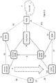
- FIG. 1 depicts a user equipment (UE) 10 in the process of handing over between two base stations (eNodeB) 1, 11.
- the base stations are connected to through respective mobile management entities (2, 12) to respective serving gateways 3, 13.
- the mobile management entities 2, 12 are also in communication with a HSS (Home Subscriber Server) and policy and charging rule function (PCRF) 4 which handles permanent user data, charging policies, limitations on access to the system etc.
- the serving gateways 3, 13 and HSS/PCRF 4 are also in communication with a public data network gateway (PGW) 6 which gives access to a public data network (PDN) such as the Internet 7.
- PGW public data network gateway
- S10 interfaces are present between the MMEs 2, 12, used for example when a user moves between areas served by different MMEs.
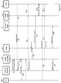
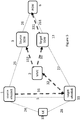
- Figure 2 , Figure 4 and the left hand side of Figure 7 illustrate the conventional S1 handover process.
- the solid lines in Figure 2 and the heavy arrows in Figure 4 indicate control signalling managed by the MME, and the dashed lines indicate the data connections.
- the initial step 21 is an interaction between the source node 1 and the source MME 2. This handover request is forwarded to the target MME 12 (step 210).
- the target MME 12 operates a resource allocation interaction 22 with the target base station 11 and an interaction with the target gateway 13 to modify the bearer links 25, 24 such that a new GTP link 261, 27, 28 is connected between the PDN gateway 6 and the user terminal 10 by way of the target gateway 13, target MME 12 and target node 11.
- the source MME 2 passes the handover instruction to the user terminal 10 (steps 221, 222) after which data can be transmitted over the new connection 27, 28 to and from the user terminal 10.
- Downlink data already received by the source node 1 over the old data link 25 from the source gateway 3 has to be forwarded to the target node 11 for onward transmission over the new link 28. This is generally achieved by creating a "tunnel" between the source eNodeB 1 and the taregt eNodeB 11.
- the tunnel is set up by a control message 211, 212 from the MMEs 2, 12 to their associated gateways 3,13 allowing data received by the source node 1 to be returned to the source gateway 3, and transmitted over a link 251 to the target gateway 13 from where it can be forwarded over the new links 27, 28 This may be either directly between the nodes 1, 11 or, as shown, by way of the gateway 3 (or gateways 3, 13) and the links 25, 27 between the gateway and the respective nodes 1, 11.
- the target MME 12 transmits signals 232, 23 to the source MME 2, and target gateway 13 indicating that the routing is to be modified.
- the target gateway 13 forwards this routing change signal 231 to the PDN gateway 6 to cause incoming data destined for the terminal 10 to be routed to the target gateway 13 (link 261) instead of the source gateway (link 26).
- the source MME 2 signals to the source node 1, source gateway 3 and PDN gateway that the links can be released and the forwarding tunnel shut down (step 39)
- the new link 28 cannot be established in this process until the handover instructions 21, 210, 22 have been passed by way of the MMEs 2, 12. If signal strength over the initial link 24 is being lost rapidly this can result in a loss of signal, resulting in an interruption or increased latency to the session.
- Figure 3 , Figure 5 and the right hand side of Figure 7 illustrate the prior art X2 handover process.
- the solid lines in Figure 3 and the heavy arrows in Figure 5 indicate control signalling managed by the MME, and the dashed lines indicate data links.
- This process provides a simpler handover procedure than the S1 process described above when the two nodes 1, 11 are managed by the same MME 2.
- the X2 handover process can be mediated directly between the nodes (eNode B) 1, 11 involved in the handover.
- the initial handover step 31 is an interaction between the nodes 1, 11.
- Downlink data received by the source node 1 over the initial downlink 25 can be forwarded 310 to the target node 11 for downlink 28 to the terminal before the change is reported to the MME 2 (step 32).
- the handover is arranged between the access nodes 1, 11, and downlink data can be forwarded from the source node 1 to the target node 11 before a message is sent to the source MME 2 to establish new backhaul connections 261, 27 and close the original connections 25, 26. Therefore, unlike in the S1 situation, the MME 2 only gets involved after the new wireless connection 28 has been established. This allows much faster handover.
- the source MME 2 transmits a session request 33 to the target gateway 13 to set up a new direct link 27 to the target node 11, and will in turn send a message 331 to the PDN gateway 6 to divert traffic for the user terminal 1 to be routed via the target gateway 13.
- a further signal 332 is sent to the source gateway to close the bearer link 25 to the source node 1.
- This sequence provides for better continuity of service as the link 28 between the terminal 10 and the target node 11 is established earlier in the procedure, reducing the risk of the session dropping out if the link 24 is lost.
- the X2 mode is quicker than S1, but current standards do not allow for X2-based handover unless both eNBs 1, 11 are connected to the same MME (2).
- the present invention provides for handovers between nodes 1, 11 working to different MMEs 2, 12.
- a node 1 (hereinafter referred to as the source node, and indicated by dashed lines in Figure 7 ) initiates a handover (step 41) it transmits a flag 90 to the target node 11 indicating that it is capable of supporting an inter-MME handover process, and identifying the address of its associated MME 2.
- the source node 1 will be aware, from an internal database 841 of neighbouring nodes, whether the target node is also capable of supporting the inter-MME process, and will only initiate the process if that is the case: otherwise initiating an S1 Type handover as illustrated in Figures 2 and 3 (steps 22 onwards).
- a target node 11 not capable of supporting the inter-MME handover process receives a message with the flag 90 it will detect the flag as an error and reject the handover, after which the source node will attempt an S1 type handover.
- the former process is preferred as it reduces the delay caused by the rejection and re-attempt.
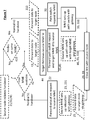
- a target node 11 capable of supporting the inter-MME handover process receives a handover request 21/31/41 it first determines whether the source node 1 works to the same MME 2, as the target node 12 does (step 410, and see figure 3 ), and if this is the case it initiates a normal X2 handover process 31, 32, 33. Otherwise, if the source node 1 does not support the process step 42 it initiates the S1-type process described with respect to Figures 2 and 3 (steps 22, 23, 25).
- the flag is either not sent, or is rejected, and the source node then either initiates a normal S1 handover, or an X2 handover if both nodes work to the same MME.
- the flag 90 is both generated by the source node 1 and detected by the target node 11, and a data link 43 is established over which data may be forwarded to the target node.
- the target node on detecting the flag indicating an inter-MME handover (step 44) establishes a new downlink 28 with the terminal over which data received over a link 43 from the source node 1 may be forwarded. It should be noted that at this stage the actual handover of the wireless connection of the terminal 10 from source node 1 target node 11 has already taken place. The remaining process is required to transfer the backhaul connections 25, 26, between the nodes and the PDN gateway 6 to operate by the new route 27, 261. In order to do this, the target node 11 transmits a change path request 32 to its respective MME 12, together with the information 44 carried by the flag 90 relating to the source MME 2.
- the target MME 12 On receiving a change path request 32 with the flag 90, the target MME 12 extracts the address data of the source MME 2 (step 44) and sets up an interface with the source MME 2 to allow the relocation (path change) to be co-ordinated (step 43).
- the target MME 12 can process the session request with its associated serving gateway 13 (step 33), allowing the PDN gateway 6 to modify the bearer data (step 331).
- the remainder of the handover is managed by the target MME 12, with the additional step of transmitting a notification 45 to the source MME 2 to indicate that the session has been transferred to the target MME 12, allowing the source MME to close down the original session with its serving gateway 3 (step 46). It also informs the source MME 2 of the identity of the gateway 13 associated with the target MME 12 so that, if it is different, the source MME 2 can instruct its own associated gateway 3 to drop the session (step 38).
- the target MME 12 can forward an acknowledgement to the target node 11 (step 29) which can then instruct the source node to release its resources (step 39)
- Figure 8 is a diagram illustrating schematically the functional elements of an access node capable of operation according to the invention.
- Figure 9 is a diagram illustrating schematically the functional elements of an access control system according to the invention. It will be appreciated that these elements may be implemented by software.
- the handover process involves co-operation between two access nodes of the general type depicted in Figure 8 , operating through two access control systems of the general type depicted in Figure 9 , although in both cases the nodes and access control systems may differ in detail.
- the access node in figure 8 can operate the process described above acting as either a source node 1 or a target node 11. It comprises a wireless interface 80 for communicating with one or more co-operating user terminals 10, and a network connection 82 through which the access node may be connected to other access nodes 1, 11, a network gateway (SGW) 3, 13, and a handover control system (MME) 2, 12.
- a switching system 81 controls the routing of data from the various inputs and addressing for onward transmission.
- a data receiving function 88 and data transmission function 89 process data being passed through the access point, providing functions such as buffering or reformatting.
- a handover processing unit 8 comprises a quality monitoring function 83 for measuring the quality of the wireless link 24, 28 between the interface 80 and any user terminal 10 currently connected to the access node, providing an input to a handover initiation processor 84.
- the handover initiation processor transmits a handover initiation signal over the network connection 82, and virtual link 5 to a target access node 11.
- This signal includes a flag generated by a flag generation unit 85 indicating that the access point is associated with a handover control system 2 capable of supporting a handover, and identifying that handover control system. This identity will have been provided to the flag generator 85 by the handover control system (MME) 2 by way of the link 32 and the network connection 82, as will be described with reference to Figure 9 .
- MME handover control system
- the handover processor 8 also has an incoming handover processor 86 for processing handover requests generated by other access points 1, and received over the virtual connection 5 through the network connection 82, allowing the access point to operate as a target node 11.
- incoming handover processor 86 for processing handover requests generated by other access points 1, and received over the virtual connection 5 through the network connection 82, allowing the access point to operate as a target node 11.
- a flag monitor 87 Associated with this processor 86 is a flag monitor 87. If the flag monitor detects a flag in an incoming request, it forwards the data in the flag, which includes the identity of the source handover control unit 3, to its associated access control system (MME) 12.
- MME access control system
- Figure 9 depicts an access control system capable of operation as either a source MME 2 or a target MME 12 according to the invention. It has signalling connections 21, 22 to the access nodes 1, 11 under its control, a further connection 211, 212 to one or more service gateways 3,13 and a further connection 210 to other access control systems 2,12. It has a handover processing function 9, 19 which generates instructions to the access nodes 1, 11, gateways 3,13 and other access control systems 2 in order to establish and release communications links between them as part of the handover process, in response to handover requests transmitted from another access control system 1 either directly, or by way of a gateway 13 or another handover control system 12.
- Separate functions 9, 19 are depicted, respectively for operation of the system as a source or a target.
- a path switch request-receiving function 96 which has an associated monitoring function 97 to identify whether a source MME 2 is identified in a flag carried by the path switch data. If such data are present, the handover processor 19 mediates the handover process with that other access control system (MME) 2. If no such flag data is present, the request is forwarded by way of a gateway interface 98 to the associated gateway 3.
- MME access control system
- the handover processing unit 9 may receive requests for handover either from the associated gateway 3 or from another access control system 12, depending on whether the target system 12 is also enabled to operate the inter MME handover process of the invention.
- the access control system also has a flag generation unit 95 for generating data identifying the unit as having the capability to co-operate directly with similar units and transmitting that data to access nodes 1,11 to which it is connected in order to programme their flag generators 8 ( Figure 8 )
Landscapes
- Engineering & Computer Science (AREA)
- Computer Networks & Wireless Communication (AREA)
- Signal Processing (AREA)
- Mobile Radio Communication Systems (AREA)
Claims (4)
- Mobilkommunikation-Zugangsknoten (11) zum Bereitstellen einer Kommunikationsverbindung zwischen einem Benutzerendgerät und einem Netz, wobei der Zugangsknoten Folgendes aufweist:einen Weiterreichungsprozessor (8) zum Verarbeiten von Weiterreichungsanforderungen, wobei der Weiterreichungsprozessor ausgelegt ist zum Detektieren eines Signals, das von einem anderen Zugangsknoten (1) empfangen wird, der einem ersten Weiterreichungs-Steuersystem (2) zugeordnet ist, Weiterreichen einer Verbindung mit einem Benutzerendgerät (10) und Weiterleiten der Anforderung zu einem zweiten Weiterreichungs-Steuersystem (12), das dem Mobilkommunikations-Zugangsknoten zugeordnet ist,einen Datensender (89) zum Senden von Daten, die von dem anderen Zugangsknoten empfangen werden, zu dem Benutzerendgerätund einen Datenempfänger (88) zum Empfangen von für das Benutzerendgerät bestimmten Daten von dem anderen Zugangsknoten,wobeider Weiterreichungsprozessor ausgelegt ist zum Erzeugen einer Pfadwechselanforderung (32), die gekennzeichnet ist, um dem zweiten Weiterreichungs-Steuersystem anzugeben, dass der Weiterreichungsprozessor zu Kooperation mit einem anderen Zugangsknoten in der Lage ist, um eine Weiterreichung zu bewirken,und eine Überwachungsvorrichtung (87) zum Identifizieren der Anwesenheit einer Kennzeichnung (90) in einer Weiterreichungsanforderung, wobei die Kennzeichnung den die Anforderung sendenden Zugangsknoten (1) identifiziert und ein erstes Weiterreichungs-Steuersystem mit diesem Zugangsknoten identifiziert und angibt, dass das erste Weiterreichungs-Steuersystem zu Kooperation mit Weiterreichungs-Steuersystemen einer Klasse in der Lage ist, zu der das zweite Weiterreichungssystem gehört, um eine Weiterreichung zu bewirken, wobei der Weiterreichungsprozessor gemäß der Anwesenheit oder Abwesenheit der Kennzeichnung auf Weiterreichungsanforderungen reagiert, dergestalt, dass,wenn die Kennzeichnung nicht anwesend ist, dies bewirkt, dass für das Benutzerendgerät bestimmte Daten zu einem Gateway (3) umgeleitet werden, um nach Abschluss einer Weiterreichung zu einer Umleitungsadresse weitergeleitet zu werden,wenn die Kennzeichnung anwesend ist, dies bewirkt, dass Daten zu dem durch die Kennzeichnung identifizierten Zugangsknoten (11) weitergeleitet werden.
- Mobilkommunikation-Zugangsknoten nach Anspruch 1, umfassend: einen Weiterreichungsprozessor (8) zum Erzeugen einer Weiterreichungsanforderung zur Übertragung zu einem anderen Zugangsknoten, um eine Verbindung zwischen einem Benutzerendgerät und einem aktuell mittels des Zugangsknotens gerouteten Netz zu transferieren, dergestalt, dass sie mittels des anderen Zugangsknotens geroutet wird, mit einem Kennzeichnungsgenerator (85) zum Erzeugen einer Kennzeichnung (90) in der Anforderung, wobei die Kennzeichnung ein Weiterreichungs-Steuersystem identifiziert, das dem die Anforderung sendenden Zugangsknoten zugeordnet ist, und angibt, dass das Weiterreichungs-Steuersystem zu Kooperation mit einem anderen Weiterreichungs-Steuersystem in der Lage ist, um eine Weiterreichung zu bewirken.
- Weiterreichungsprozess zum Bewirken, dass eine Kommunikations-Zugangsverbindung zwischen einem Benutzerendgerät (10) und einem Kernnetz von einem ersten Routing (24) mittels eines Quellen-Zugangsknotens (1), der durch ein erstes Handover-Steuersystem (2) gesteuert wird, zu einem zweiten Routing (28) mittels eines Ziel-Zugangsknotens (11), der durch ein zweites Weiterreichungs-Steuersystem (12) gesteuert wird, umgelenkt wird, wobei der Quellen-Zugangsknoten eine Weiterreichungsanforderung zu dem Ziel-Zugangsknoten sendet, und wobei der Quellen-Zugangsknoten Weiterleitung von Daten, die von dem Netz empfangen werden und für das Benutzerendgerät bestimmt sind, einleitet, dergestalt, dass Daten von dem Quellen-Zugangsknoten zur Weiterübertragung zu dem anderen Benutzerendgerät zu dem Ziel-Zugangsknoten geroutet werden,
wobei der Quellen-Zugangsknoten (1) in der Lage ist, Kennzeichnungen in der Weiterreichungsanforderung zu erzeugen, die die Identität und Fähigkeiten des ersten Weiterreichungs-Steuersystems (2) angeben, von dem aus der Quellen-Zugangsknoten gesteuert wird, und wobei, wenn Kennzeichnungsdaten durch den Quellen-Zugangsknoten erzeugt und durch den Ziel-Zugangsknoten in der Weiterreichungsanforderung detektiert werden, die Daten zu dem zweiten Weiterreichungs-Steuersystem (12) weitergeleitet werden, um einen kooperativen Prozessor zwischen dem Quellen-Handover-Steuersystem und dem Ziel-Handover-Steuersystem einzuleiten, um das zweite Routing zwischen dem Benutzerendgerät und dem Netz herzustellen, und wenn der Ziel-Zugangsknoten keine Kennzeichnung in der Weiterreichungsanforderung detektiert, die Pfadwechselanforderung zurückgewiesen wird und eine Pfadwechselanforderung von dem Quellenknoten zu seinem jeweiligen ersten Weiterreichungs-Steuersystem gesendet wird, um einen Pfadwechselprozess einzuleiten, der mittels des Kernnetzes (3, 6, 13) vermittelt wird. - Weiterreichungsprozess nach Anspruch 4, wobei, wenn der Ziel-Zugangsknoten (11) befähigt ist, eine Pfadwechselanforderung einzuleiten, er auf Detektion der Kennzeichnung (90) in einer Pfadwechselanforderung reagiert, indem er die Kennzeichnung zu dem Quellen-Zugangsknoten weitersendet, und bei Detektion der weitergesendeten Kennzeichnung der Quellen-Zugangsknoten die Herstellung des zweiten Routings (5) einleitet, und wenn der Quellenknoten keine weitergesendete Kennzeichnung detektiert, er einen mittels des Kernnetzes (6) vermittelten Pfadwechselprozess einleitet.
Applications Claiming Priority (2)
| Application Number | Priority Date | Filing Date | Title |
|---|---|---|---|
| EP14250049 | 2014-03-21 | ||
| PCT/GB2015/050626 WO2015140504A1 (en) | 2014-03-21 | 2015-03-04 | Mobile handover |
Publications (2)
| Publication Number | Publication Date |
|---|---|
| EP3120613A1 EP3120613A1 (de) | 2017-01-25 |
| EP3120613B1 true EP3120613B1 (de) | 2020-09-30 |
Family
ID=50442446
Family Applications (1)
| Application Number | Title | Priority Date | Filing Date |
|---|---|---|---|
| EP15710228.6A Active EP3120613B1 (de) | 2014-03-21 | 2015-03-04 | Mobile weiterreichung |
Country Status (3)
| Country | Link |
|---|---|
| US (1) | US9883436B2 (de) |
| EP (1) | EP3120613B1 (de) |
| WO (1) | WO2015140504A1 (de) |
Families Citing this family (32)
| Publication number | Priority date | Publication date | Assignee | Title |
|---|---|---|---|---|
| EP3241387B1 (de) | 2014-12-30 | 2021-04-28 | British Telecommunications public limited company | Zellenneuauswahl |
| WO2016107886A1 (en) | 2014-12-30 | 2016-07-07 | British Telecommunications Public Limited Company | Celular handover |
| CN107925864B (zh) | 2015-07-27 | 2021-02-05 | 苹果公司 | 虚拟移动性管理实体管理 |
| US10728816B2 (en) | 2015-12-31 | 2020-07-28 | British Telecommunications Public Limited Company | Assisted handover to VoLTE in case of VoWiFi failure |
| US10278100B1 (en) * | 2016-03-16 | 2019-04-30 | Sprint Communications Company L.P. | Long term evolution (LTE) mobility management entity (MME) management of an internet protocol multimedia subsystem (IMS) media session service level for a user equipment (UE) |
| US10757629B2 (en) | 2016-03-31 | 2020-08-25 | British Telecommunications Public Limited Company | Handover method |
| WO2017167694A1 (en) | 2016-03-31 | 2017-10-05 | British Telecommunications Public Limited Company | Voice service client device |
| EP3468253B1 (de) * | 2016-07-01 | 2021-04-14 | Huawei Technologies Co., Ltd. | Umschaltverfahren und -vorrichtung |
| KR102117098B1 (ko) * | 2017-01-12 | 2020-06-02 | 주식회사 케이티 | 이종 네트워크 핸드오버 제어 방법 및 그 장치 |
| US11271636B2 (en) | 2017-02-08 | 2022-03-08 | British Telecommunications Public Limited Company | Cellular telecommunications network |
| US11516710B2 (en) | 2017-03-24 | 2022-11-29 | British Telecommunications Public Limited Company | Cellular telecommunications network |
| CN110431860B (zh) | 2017-03-24 | 2022-03-08 | 英国电讯有限公司 | 蜂窝电信网络 |
| US11140620B2 (en) | 2017-03-31 | 2021-10-05 | British Telecommunications Public Limited Company | Access network selection |
| WO2018178294A1 (en) | 2017-03-31 | 2018-10-04 | British Telecommunications Public Limited Company | Network discovery |
| CN110463281A (zh) | 2017-03-31 | 2019-11-15 | 英国电讯有限公司 | 接入网络选择 |
| CN114531713B (zh) * | 2017-05-05 | 2025-03-07 | 索尼公司 | 通信装置、基础设施设备、方法、电路及无线通信系统 |
| EP3643113A1 (de) | 2017-06-23 | 2020-04-29 | British Telecommunications Public Limited Company | Sprachdienstübergabe |
| WO2018234038A1 (en) | 2017-06-23 | 2018-12-27 | British Telecommunications Public Limited Company | Voice service handover |
| EP3751896B1 (de) * | 2018-02-09 | 2026-03-11 | Beijing Xiaomi Mobile Software Co., Ltd. | Handover-entscheidung auf basis von corenetzkompatibilität |
| US11405849B2 (en) | 2018-03-28 | 2022-08-02 | British Telecommunications Public Limited Company | Roaming route optimization |
| CN111903180B (zh) | 2018-03-28 | 2021-08-06 | 英国电讯有限公司 | 在无线通信网络中为设备建立承载的方法和装置 |
| US11337262B2 (en) | 2018-03-28 | 2022-05-17 | British Telecommunications Public Limited Company | Predictive bearers in a wireless communication network |
| US11337077B2 (en) | 2018-03-29 | 2022-05-17 | British Telecommunications Public Limited Company | Method of channel selection in a wireless network |
| EP3777461B1 (de) | 2018-03-29 | 2024-08-07 | British Telecommunications public limited company | Dediziertes trägermanagement |
| US20190045005A1 (en) * | 2018-04-12 | 2019-02-07 | Intel Corporation | Method for replicating data in a network and a network component |
| WO2020078730A1 (en) | 2018-10-16 | 2020-04-23 | British Telecommunications Public Limited Company | Measuring channel performance in wireless local area networks |
| US11985725B2 (en) * | 2019-03-19 | 2024-05-14 | Apple Inc. | Signaling for inactive small data transmission without path switching |
| US10932163B1 (en) | 2019-07-22 | 2021-02-23 | Sprint Spectrum L.P. | Controlling handover based on source and target capabilities with respect to dual connectivity |
| EP3772227B1 (de) | 2019-07-29 | 2022-07-13 | British Telecommunications public limited company | Zellulares telekommunikationsnetzwerk |
| US11812320B2 (en) | 2019-07-29 | 2023-11-07 | British Telecommunications Public Limited Company | Initiation of transfer of user equipment to base station according to visual data |
| CN114079870B (zh) * | 2020-08-13 | 2023-06-02 | 华为技术有限公司 | 通信方法及装置 |
| US11729692B2 (en) * | 2021-06-25 | 2023-08-15 | T-Mobile Usa, Inc. | Mobility management for mobile device edge computing |
Family Cites Families (7)
| Publication number | Priority date | Publication date | Assignee | Title |
|---|---|---|---|---|
| WO2007103369A2 (en) * | 2006-03-07 | 2007-09-13 | Interdigital Technology Corporation | Method and apparatus for supporting handoff in an lte gtp based wireless communication system |
| US20070254667A1 (en) * | 2006-04-28 | 2007-11-01 | Joanna Jokinen | Inter-MME handover in evolved communication systems |
| JP4848890B2 (ja) | 2006-08-23 | 2011-12-28 | 日本電気株式会社 | 移動通信システム及びその方法並びにそれに用いる基地局 |
| DK2312892T3 (da) * | 2009-10-16 | 2013-08-26 | Teliasonera Ab | Fremgangsmåde til udførelse af handover i et mobilkommunikationssystem |
| CN102300190B (zh) * | 2010-06-28 | 2013-01-23 | 华为技术有限公司 | 切换方法、通信装置和通信系统 |
| CN102595534B (zh) | 2011-01-10 | 2014-12-03 | 华为技术有限公司 | 用户设备上下文相关资源的释放方法和设备 |
| WO2015087042A1 (en) | 2013-12-03 | 2015-06-18 | British Telecommunications Public Limited Company | Mobile handover |
-
2015
- 2015-03-04 EP EP15710228.6A patent/EP3120613B1/de active Active
- 2015-03-04 WO PCT/GB2015/050626 patent/WO2015140504A1/en not_active Ceased
- 2015-03-04 US US15/127,555 patent/US9883436B2/en active Active
Non-Patent Citations (1)
| Title |
|---|
| None * |
Also Published As
| Publication number | Publication date |
|---|---|
| EP3120613A1 (de) | 2017-01-25 |
| WO2015140504A1 (en) | 2015-09-24 |
| US9883436B2 (en) | 2018-01-30 |
| US20170142624A1 (en) | 2017-05-18 |
Similar Documents
| Publication | Publication Date | Title |
|---|---|---|
| EP3120613B1 (de) | Mobile weiterreichung | |
| US12262269B2 (en) | Communication system | |
| US8447304B2 (en) | Mobile communication system and access gateway having plural user plane AGWs | |
| RU2659405C2 (ru) | Аппарат связи, узел опорной сети, система, компьютерная программа и способы для перемаршрутизации сообщений nas | |
| RU2564402C2 (ru) | Способы и устройство для управления передачей обслуживания между базовыми станциями | |
| EP2781123B1 (de) | Durchführung von mobilitätslastausgleich und mobilitätsrobustheitsoptimierung zwiscen zugangsknoten für nur eine untergruppe von benutzergeräten | |
| CN108200620B (zh) | 无线电台、无线电终端、用于无线电台的方法以及用于无线电终端的方法 | |
| US8837395B2 (en) | Method and entity for conveying data units | |
| US20140119340A1 (en) | Traffic offload via local network based on apn-specific or non-apn-specific information | |
| JP6463801B2 (ja) | ハンドオーバー失敗防止方法 | |
| CN102868994A (zh) | 一种支持用户设备ue移动性的方法 | |
| EP2930977B1 (de) | Verfahren zum Betrieb einer Basisstation | |
| JP2019521588A (ja) | 通信制御方法および関連するネットワーク要素 | |
| EP2200369A2 (de) | Verfahren und Vorrichtung zur Übergabe zwischen heterogenen Netzwerken | |
| KR20150038451A (ko) | 3gpp 무선 액세스 기술 간 핸드오버 시의 ip 트래픽 분산 방법 및 장치 | |
| WO2018035741A1 (zh) | 策略控制方法、网元、系统及存储介质 | |
| JP2018508155A (ja) | 通信システム | |
| EP3529954B1 (de) | Verfahren und vorrichtungen zur anbindung einer basisstation an ein kernnetzwerk | |
| EP2574104B1 (de) | Verfahren, vorrichtung und system zum umschalten von kommunikationswegen | |
| KR20140082072A (ko) | 데이터 트래픽 전환 유도 시스템 및 방법 | |
| GB2638392A (en) | Conditional handover with target secondary node |
Legal Events
| Date | Code | Title | Description |
|---|---|---|---|
| STAA | Information on the status of an ep patent application or granted ep patent |
Free format text: STATUS: THE INTERNATIONAL PUBLICATION HAS BEEN MADE |
|
| PUAI | Public reference made under article 153(3) epc to a published international application that has entered the european phase |
Free format text: ORIGINAL CODE: 0009012 |
|
| STAA | Information on the status of an ep patent application or granted ep patent |
Free format text: STATUS: REQUEST FOR EXAMINATION WAS MADE |
|
| 17P | Request for examination filed |
Effective date: 20161021 |
|
| AK | Designated contracting states |
Kind code of ref document: A1 Designated state(s): AL AT BE BG CH CY CZ DE DK EE ES FI FR GB GR HR HU IE IS IT LI LT LU LV MC MK MT NL NO PL PT RO RS SE SI SK SM TR |
|
| AX | Request for extension of the european patent |
Extension state: BA ME |
|
| DAV | Request for validation of the european patent (deleted) | ||
| DAX | Request for extension of the european patent (deleted) | ||
| RAP1 | Party data changed (applicant data changed or rights of an application transferred) |
Owner name: BRITISH TELECOMMUNICATIONS PUBLIC LIMITED COMPANY |
|
| STAA | Information on the status of an ep patent application or granted ep patent |
Free format text: STATUS: EXAMINATION IS IN PROGRESS |
|
| 17Q | First examination report despatched |
Effective date: 20190828 |
|
| GRAP | Despatch of communication of intention to grant a patent |
Free format text: ORIGINAL CODE: EPIDOSNIGR1 |
|
| STAA | Information on the status of an ep patent application or granted ep patent |
Free format text: STATUS: GRANT OF PATENT IS INTENDED |
|
| INTG | Intention to grant announced |
Effective date: 20200512 |
|
| GRAS | Grant fee paid |
Free format text: ORIGINAL CODE: EPIDOSNIGR3 |
|
| GRAA | (expected) grant |
Free format text: ORIGINAL CODE: 0009210 |
|
| STAA | Information on the status of an ep patent application or granted ep patent |
Free format text: STATUS: THE PATENT HAS BEEN GRANTED |
|
| AK | Designated contracting states |
Kind code of ref document: B1 Designated state(s): AL AT BE BG CH CY CZ DE DK EE ES FI FR GB GR HR HU IE IS IT LI LT LU LV MC MK MT NL NO PL PT RO RS SE SI SK SM TR |
|
| REG | Reference to a national code |
Ref country code: CH Ref legal event code: EP Ref country code: GB Ref legal event code: FG4D |
|
| REG | Reference to a national code |
Ref country code: DE Ref legal event code: R096 Ref document number: 602015059775 Country of ref document: DE Ref country code: AT Ref legal event code: REF Ref document number: 1320095 Country of ref document: AT Kind code of ref document: T Effective date: 20201015 |
|
| REG | Reference to a national code |
Ref country code: IE Ref legal event code: FG4D |
|
| PG25 | Lapsed in a contracting state [announced via postgrant information from national office to epo] |
Ref country code: FI Free format text: LAPSE BECAUSE OF FAILURE TO SUBMIT A TRANSLATION OF THE DESCRIPTION OR TO PAY THE FEE WITHIN THE PRESCRIBED TIME-LIMIT Effective date: 20200930 Ref country code: GR Free format text: LAPSE BECAUSE OF FAILURE TO SUBMIT A TRANSLATION OF THE DESCRIPTION OR TO PAY THE FEE WITHIN THE PRESCRIBED TIME-LIMIT Effective date: 20201231 Ref country code: BG Free format text: LAPSE BECAUSE OF FAILURE TO SUBMIT A TRANSLATION OF THE DESCRIPTION OR TO PAY THE FEE WITHIN THE PRESCRIBED TIME-LIMIT Effective date: 20201230 Ref country code: NO Free format text: LAPSE BECAUSE OF FAILURE TO SUBMIT A TRANSLATION OF THE DESCRIPTION OR TO PAY THE FEE WITHIN THE PRESCRIBED TIME-LIMIT Effective date: 20201230 Ref country code: HR Free format text: LAPSE BECAUSE OF FAILURE TO SUBMIT A TRANSLATION OF THE DESCRIPTION OR TO PAY THE FEE WITHIN THE PRESCRIBED TIME-LIMIT Effective date: 20200930 Ref country code: SE Free format text: LAPSE BECAUSE OF FAILURE TO SUBMIT A TRANSLATION OF THE DESCRIPTION OR TO PAY THE FEE WITHIN THE PRESCRIBED TIME-LIMIT Effective date: 20200930 |
|
| REG | Reference to a national code |
Ref country code: AT Ref legal event code: MK05 Ref document number: 1320095 Country of ref document: AT Kind code of ref document: T Effective date: 20200930 |
|
| PG25 | Lapsed in a contracting state [announced via postgrant information from national office to epo] |
Ref country code: RS Free format text: LAPSE BECAUSE OF FAILURE TO SUBMIT A TRANSLATION OF THE DESCRIPTION OR TO PAY THE FEE WITHIN THE PRESCRIBED TIME-LIMIT Effective date: 20200930 Ref country code: LV Free format text: LAPSE BECAUSE OF FAILURE TO SUBMIT A TRANSLATION OF THE DESCRIPTION OR TO PAY THE FEE WITHIN THE PRESCRIBED TIME-LIMIT Effective date: 20200930 |
|
| REG | Reference to a national code |
Ref country code: NL Ref legal event code: MP Effective date: 20200930 |
|
| REG | Reference to a national code |
Ref country code: LT Ref legal event code: MG4D |
|
| PG25 | Lapsed in a contracting state [announced via postgrant information from national office to epo] |
Ref country code: CZ Free format text: LAPSE BECAUSE OF FAILURE TO SUBMIT A TRANSLATION OF THE DESCRIPTION OR TO PAY THE FEE WITHIN THE PRESCRIBED TIME-LIMIT Effective date: 20200930 Ref country code: PT Free format text: LAPSE BECAUSE OF FAILURE TO SUBMIT A TRANSLATION OF THE DESCRIPTION OR TO PAY THE FEE WITHIN THE PRESCRIBED TIME-LIMIT Effective date: 20210201 Ref country code: LT Free format text: LAPSE BECAUSE OF FAILURE TO SUBMIT A TRANSLATION OF THE DESCRIPTION OR TO PAY THE FEE WITHIN THE PRESCRIBED TIME-LIMIT Effective date: 20200930 Ref country code: NL Free format text: LAPSE BECAUSE OF FAILURE TO SUBMIT A TRANSLATION OF THE DESCRIPTION OR TO PAY THE FEE WITHIN THE PRESCRIBED TIME-LIMIT Effective date: 20200930 Ref country code: EE Free format text: LAPSE BECAUSE OF FAILURE TO SUBMIT A TRANSLATION OF THE DESCRIPTION OR TO PAY THE FEE WITHIN THE PRESCRIBED TIME-LIMIT Effective date: 20200930 Ref country code: SM Free format text: LAPSE BECAUSE OF FAILURE TO SUBMIT A TRANSLATION OF THE DESCRIPTION OR TO PAY THE FEE WITHIN THE PRESCRIBED TIME-LIMIT Effective date: 20200930 |
|
| PG25 | Lapsed in a contracting state [announced via postgrant information from national office to epo] |
Ref country code: PL Free format text: LAPSE BECAUSE OF FAILURE TO SUBMIT A TRANSLATION OF THE DESCRIPTION OR TO PAY THE FEE WITHIN THE PRESCRIBED TIME-LIMIT Effective date: 20200930 Ref country code: IS Free format text: LAPSE BECAUSE OF FAILURE TO SUBMIT A TRANSLATION OF THE DESCRIPTION OR TO PAY THE FEE WITHIN THE PRESCRIBED TIME-LIMIT Effective date: 20210130 Ref country code: ES Free format text: LAPSE BECAUSE OF FAILURE TO SUBMIT A TRANSLATION OF THE DESCRIPTION OR TO PAY THE FEE WITHIN THE PRESCRIBED TIME-LIMIT Effective date: 20200930 Ref country code: AT Free format text: LAPSE BECAUSE OF FAILURE TO SUBMIT A TRANSLATION OF THE DESCRIPTION OR TO PAY THE FEE WITHIN THE PRESCRIBED TIME-LIMIT Effective date: 20200930 Ref country code: AL Free format text: LAPSE BECAUSE OF FAILURE TO SUBMIT A TRANSLATION OF THE DESCRIPTION OR TO PAY THE FEE WITHIN THE PRESCRIBED TIME-LIMIT Effective date: 20200930 |
|
| PG25 | Lapsed in a contracting state [announced via postgrant information from national office to epo] |
Ref country code: SK Free format text: LAPSE BECAUSE OF FAILURE TO SUBMIT A TRANSLATION OF THE DESCRIPTION OR TO PAY THE FEE WITHIN THE PRESCRIBED TIME-LIMIT Effective date: 20200930 |
|
| REG | Reference to a national code |
Ref country code: DE Ref legal event code: R097 Ref document number: 602015059775 Country of ref document: DE |
|
| PLBE | No opposition filed within time limit |
Free format text: ORIGINAL CODE: 0009261 |
|
| STAA | Information on the status of an ep patent application or granted ep patent |
Free format text: STATUS: NO OPPOSITION FILED WITHIN TIME LIMIT |
|
| PG25 | Lapsed in a contracting state [announced via postgrant information from national office to epo] |
Ref country code: DK Free format text: LAPSE BECAUSE OF FAILURE TO SUBMIT A TRANSLATION OF THE DESCRIPTION OR TO PAY THE FEE WITHIN THE PRESCRIBED TIME-LIMIT Effective date: 20200930 |
|
| 26N | No opposition filed |
Effective date: 20210701 |
|
| PG25 | Lapsed in a contracting state [announced via postgrant information from national office to epo] |
Ref country code: MC Free format text: LAPSE BECAUSE OF FAILURE TO SUBMIT A TRANSLATION OF THE DESCRIPTION OR TO PAY THE FEE WITHIN THE PRESCRIBED TIME-LIMIT Effective date: 20200930 Ref country code: IT Free format text: LAPSE BECAUSE OF FAILURE TO SUBMIT A TRANSLATION OF THE DESCRIPTION OR TO PAY THE FEE WITHIN THE PRESCRIBED TIME-LIMIT Effective date: 20200930 |
|
| REG | Reference to a national code |
Ref country code: CH Ref legal event code: PL |
|
| PG25 | Lapsed in a contracting state [announced via postgrant information from national office to epo] |
Ref country code: SI Free format text: LAPSE BECAUSE OF FAILURE TO SUBMIT A TRANSLATION OF THE DESCRIPTION OR TO PAY THE FEE WITHIN THE PRESCRIBED TIME-LIMIT Effective date: 20200930 |
|
| REG | Reference to a national code |
Ref country code: BE Ref legal event code: MM Effective date: 20210331 |
|
| PG25 | Lapsed in a contracting state [announced via postgrant information from national office to epo] |
Ref country code: LI Free format text: LAPSE BECAUSE OF NON-PAYMENT OF DUE FEES Effective date: 20210331 Ref country code: LU Free format text: LAPSE BECAUSE OF NON-PAYMENT OF DUE FEES Effective date: 20210304 Ref country code: CH Free format text: LAPSE BECAUSE OF NON-PAYMENT OF DUE FEES Effective date: 20210331 Ref country code: IE Free format text: LAPSE BECAUSE OF NON-PAYMENT OF DUE FEES Effective date: 20210304 |
|
| PG25 | Lapsed in a contracting state [announced via postgrant information from national office to epo] |
Ref country code: IS Free format text: LAPSE BECAUSE OF FAILURE TO SUBMIT A TRANSLATION OF THE DESCRIPTION OR TO PAY THE FEE WITHIN THE PRESCRIBED TIME-LIMIT Effective date: 20210130 |
|
| PG25 | Lapsed in a contracting state [announced via postgrant information from national office to epo] |
Ref country code: BE Free format text: LAPSE BECAUSE OF NON-PAYMENT OF DUE FEES Effective date: 20210331 |
|
| PG25 | Lapsed in a contracting state [announced via postgrant information from national office to epo] |
Ref country code: RO Free format text: LAPSE BECAUSE OF FAILURE TO SUBMIT A TRANSLATION OF THE DESCRIPTION OR TO PAY THE FEE WITHIN THE PRESCRIBED TIME-LIMIT Effective date: 20200930 |
|
| PG25 | Lapsed in a contracting state [announced via postgrant information from national office to epo] |
Ref country code: HU Free format text: LAPSE BECAUSE OF FAILURE TO SUBMIT A TRANSLATION OF THE DESCRIPTION OR TO PAY THE FEE WITHIN THE PRESCRIBED TIME-LIMIT; INVALID AB INITIO Effective date: 20150304 |
|
| PG25 | Lapsed in a contracting state [announced via postgrant information from national office to epo] |
Ref country code: CY Free format text: LAPSE BECAUSE OF FAILURE TO SUBMIT A TRANSLATION OF THE DESCRIPTION OR TO PAY THE FEE WITHIN THE PRESCRIBED TIME-LIMIT Effective date: 20200930 |
|
| P01 | Opt-out of the competence of the unified patent court (upc) registered |
Effective date: 20230623 |
|
| PG25 | Lapsed in a contracting state [announced via postgrant information from national office to epo] |
Ref country code: MK Free format text: LAPSE BECAUSE OF FAILURE TO SUBMIT A TRANSLATION OF THE DESCRIPTION OR TO PAY THE FEE WITHIN THE PRESCRIBED TIME-LIMIT Effective date: 20200930 |
|
| PG25 | Lapsed in a contracting state [announced via postgrant information from national office to epo] |
Ref country code: MT Free format text: LAPSE BECAUSE OF FAILURE TO SUBMIT A TRANSLATION OF THE DESCRIPTION OR TO PAY THE FEE WITHIN THE PRESCRIBED TIME-LIMIT Effective date: 20200930 |
|
| PG25 | Lapsed in a contracting state [announced via postgrant information from national office to epo] |
Ref country code: TR Free format text: LAPSE BECAUSE OF FAILURE TO SUBMIT A TRANSLATION OF THE DESCRIPTION OR TO PAY THE FEE WITHIN THE PRESCRIBED TIME-LIMIT Effective date: 20200930 |
|
| PGFP | Annual fee paid to national office [announced via postgrant information from national office to epo] |
Ref country code: GB Payment date: 20260219 Year of fee payment: 12 |
|
| PGFP | Annual fee paid to national office [announced via postgrant information from national office to epo] |
Ref country code: DE Payment date: 20260219 Year of fee payment: 12 |
|
| PGFP | Annual fee paid to national office [announced via postgrant information from national office to epo] |
Ref country code: FR Payment date: 20260219 Year of fee payment: 12 |