EP3120731A1 - Aufhängevorrichtung für möbel - Google Patents
Aufhängevorrichtung für möbel Download PDFInfo
- Publication number
- EP3120731A1 EP3120731A1 EP16180723.5A EP16180723A EP3120731A1 EP 3120731 A1 EP3120731 A1 EP 3120731A1 EP 16180723 A EP16180723 A EP 16180723A EP 3120731 A1 EP3120731 A1 EP 3120731A1
- Authority
- EP
- European Patent Office
- Prior art keywords
- furniture
- suspension device
- actuating
- support arm
- actuating element
- Prior art date
- Legal status (The legal status is an assumption and is not a legal conclusion. Google has not performed a legal analysis and makes no representation as to the accuracy of the status listed.)
- Granted
Links
Images


Classifications
-
- A—HUMAN NECESSITIES
- A47—FURNITURE; DOMESTIC ARTICLES OR APPLIANCES; COFFEE MILLS; SPICE MILLS; SUCTION CLEANERS IN GENERAL
- A47B—TABLES; DESKS; OFFICE FURNITURE; CABINETS; DRAWERS; GENERAL DETAILS OF FURNITURE
- A47B95/00—Fittings for furniture
- A47B95/008—Suspension fittings for cabinets to be hung on walls
-
- A—HUMAN NECESSITIES
- A47—FURNITURE; DOMESTIC ARTICLES OR APPLIANCES; COFFEE MILLS; SPICE MILLS; SUCTION CLEANERS IN GENERAL
- A47B—TABLES; DESKS; OFFICE FURNITURE; CABINETS; DRAWERS; GENERAL DETAILS OF FURNITURE
- A47B96/00—Details of cabinets, racks or shelf units not covered by a single one of groups A47B43/00 - A47B95/00; General details of furniture
- A47B96/06—Brackets or similar supporting means for cabinets, racks or shelves
- A47B96/07—Brackets or similar supporting means for cabinets, racks or shelves adjustable in themselves
Definitions
- the invention relates to a suspension device for furniture, in particular cupboard furniture or the like, with at least one hanger which has a base part attachable to the furniture part and a support arm which is mounted in its position of use in a wall holder, wherein the hanger has an adjusting device, with a relative adjustment of support arm and base part to each other at least in a spatial direction for setting a desired spatial position of the furniture is possible in which at least one accessible to the user actuating element of the adjusting device for initiating the adjustment is actuated.
- Such suspension devices for furniture are already known according to a documentally undetectable prior art.
- a suspension device has a housing in which a support arm for height and depth adjustment is adjustably mounted. The height and depth adjustment is carried out by operating two adjusting screws each supported on the housing. An adjusting screw for the height and the other adjustment screw is responsible for the depth adjustment.
- the object of the invention is therefore to provide a suspension device for furniture of the type mentioned, which can be operated quickly and reliably even under the previously described installation conditions to make an adjustment of the furniture with respect to the wall bracket.
- the suspension device for furniture according to the invention is characterized in that the at least one actuating element has an actuating portion for tool-free operation by the user.
- the tool-free to be actuated operating portion of the actuating element offers the user the ability to grip with his fingers the actuating portion and perform an adjustment. Adjustment tools, such as screwdrivers, are not necessary for this purpose. Therefore, the suspension device can be used even in confined spaces, for example, when a flap fitting is mounted in front of it or at close distances to other furniture components, such as a shelf, reliable.
- a plurality of actuatable actuating elements without tools are provided, of which a first actuating element for depth adjustment of the furniture and a second actuator for height adjustment of the furniture are provided.
- the at least one actuating element on the one hand movably mounted on the base part and on the other hand coupled to the support arm, that in the suspended state in the wall holder use of the support arm impressed by the user the actuating portion actuating movement by means of conversion into a linear movement of the base member relative to the Support arm is implemented.
- the actuating portion is designed such that a tool-free producible rotational movement can be imposed on it.
- This rotational movement can then be converted by means of the Umsetzstoff in the linear movement for height and / or depth adjustment.
- the aufoniagbare rotary motion has the advantage that the actuating element, which is usually beyond the periphery of the base part to be comfortably gripped, does not carry out extensive space linear motion, which is particularly in cramped installation situations of advantage and also the suspension of the size can be kept small ago.
- the actuating element in addition to the actuating portion on a motion coupled with this coupling portion for coupling with the support arm.
- the conversion means on the force transmission on an introduced by the user on the operating portion actuating force in a particular opposite this significantly greater adjustment for adjusting the furniture.
- the transmission means to a transmission.
- the transmission is expediently switched on between the actuating section and the coupling section of the actuating element.
- the transmission may be a positive gear or a non-positive transmission.
- Gearboxes, cycloidal gears, worm gears, chain drives, toothed belt transmissions, etc. can be used as positive-locking transmissions, for example.
- WälzEffe, in particular friction gear, for example are used as a non-positive transmission belt drive.
- the transmission is designed as a gear transmission or belt transmission or friction gear.
- the transmission is formed in one or more stages.
- the at least one actuating element is helically formed, with a manually operated without tools operating portion in the form of a particular large diameter screw head and a coupling portion in the form of a with a to the conversion means counting screw threaded screw shaft.
- the actuating element is designed as a manually operable screw.
- the screw-like actuator is designed as a thumbscrew.
- an embodiment as a thumbscrew would be conceivable.
- the base part is formed as a housing in which the adjusting device and a bearing portion of the support arm are accommodated.
- the housing has at least one housing opening, via which the actuating portion of the at least one actuating element is accessible to the user.
- the suspension device comprises a wall holder.
- the wall holder is to be fastened by means of fasteners on an associated building wall.
- the invention further comprises a piece of furniture, in particular cupboard furniture, which is characterized by a suspension device according to one of claims 1 to 14.
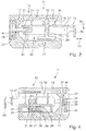
- FIGS. 1, 2 . 4 and 5 show a first embodiment of the suspension device 11 according to the invention for furniture.
- the suspension device 11 is particularly suitable for hanging a cabinet furniture, for example in the form of an upper cabinet.
- the suspension device 11 could also be referred to as a cabinet trailer.
- the function of the suspension device 11 as a cabinet hanger is exemplified when used for hanging a cabinet cabinet, although the application is not limited to cabinet furniture.
- the suspension device 11 has a hanger 12 which comprises a base part 13 attachable to the furniture part and a support arm 14.
- the base member 13 is formed according to the described embodiments as a housing.
- the housing has two housing parts 15a, 15b which are joined together and receive a portion of the support arm 14 between them.
- the front housing part 15a has a plurality, in particular three transverse to the longitudinal direction of the housing mounting holes 17 to Receiving associated fastening means, in particular fastening screws (not shown), via which the hanger 12 is attached to an associated side wall of the furniture part, for example, overhead cabinet.
- the two housing parts 15a, 15b form a receiving space 18 for the support arm 14 in the assembled state.
- the rear housing part 15b is also penetrated by the mounting holes 17 and is in the attached state on the side wall of the furniture part.
- the housing of the hanger 12 has on its front side a window-like recess 19, from which the support arm 14 protrudes from the receiving space 18 to the outside.
- slot-like openings 20, 21 through which respective components of an adjusting device 22 belonging to the suspension device 11 protrude from the housing are located on the front housing part 15a.
- the base part 13 of the hanger 12 relative to the support arm 14 at least in a spatial direction to adjust a desired spatial position of the furniture with respect to.
- the in FIG. 2 illustrated wall bracket 23 is exemplified in the form of a wall rail.
- the wall rail made of structural steel.
- the wall rail has a base portion 24 which has a plurality of mounting holes through which it can be attached to a building wall.
- the wall rail further has a hooking portion 25 which is integrally connected to the base portion 24 and in mounted state of the wall rail from the base portion projects forward away.
- the support arm 14 in addition to the suspension bracket 26, which protrudes from the window-like recess 19 of the housing, nor a base portion 27 on which attack the components of the adjusting device 22, whereby the housing relative to the support arm 14 for height and / or depth adjustment of Cabinet furniture can be adjusted.
- the adjusting device 22 for the relative adjustment of the support arm 14 and base part 13 has at least one accessible to the user actuating element 28 for initiating an adjustment movement.
- two actuators 28, 29 are provided, of which a first actuator 28 for depth adjustment of the cabinet furniture and a second actuator 29 are provided for height adjustment of the cabinet furniture.
- the at least one actuating element 28, 29 has an actuating portion 30 for tool-free operation by the user.
- both actuators 28, 29 each have an actuating portion 30 for tool-free operation by the user.
- the actuators 28, 29 are helical and in particular have the shape of a thumbscrew.
- the actuator 28 has a knurled screw head with relatively large diameter, which forms the actuating portion 30 of the respective actuating element 28, 29.
- the screw head or the actuating portion 30 protrudes a little way out of the associated slot-like opening 20, 21, which is located at the front of the first housing part 15 a. From there, the knurled trained screw head can be gripped by the fingers of the user, whereby an adjusting movement in the form of a tool-free producible rotary motion on the system housing support arm 14 can be introduced.
- the first slot-like opening 20 extends in the height direction of the housing and is associated, for example, at the opposite of the window-like recess 19 for taking out the hanger 26 end face opposite other end face.
- the clear opening of the first window-like recess 20 is greater than the diameter of the screw head or actuating portion 30 of the actuating element 28th
- the second slot-like opening 21 extends in the longitudinal direction of the housing, wherein here, too, the clear width of the second slot-like opening 21 is significantly larger than the associated screw head or operating section 30 of the second actuating element 29.
- the trained as knurled screws actuators 28, 29 have in addition to the operating portion with this motion-coupled coupling portion 31 for coupling with the support arm 14.
- the coupling portion 30 of a respective actuating element 28, 29 formed in several parts and has a screw shaft 32 which is equipped with a screw thread 33 and a trained in the support arm 14 threaded hole 34 passes.
- the coupling section 31 of the first actuating element 28 is accommodated in the support arm 14 in a threaded bore 34 aligned in the depth adjustment direction 35.
- the coupling portion 31 or screw shaft with screw thread 33 of the second actuating element 29 is received in a perpendicular to the depth adjustment direction 35 aligned height-adjustment direction 36 extending threaded bore 34 in the support arm 14 and passes through this threaded bore 34th
- the adjusting device 22 further has conversion means for implementing the particular in particular the respective operating portion 30 of the actuating element 28, 29 impressed rotational movement in a linear movement of the base member 13 and the housing relative to the support arm 14.
- the conversion means have transmission means in the form of a transmission 37, with which translates into a force translation of an introduced by the user on the associated operating portion 30 actuating force in relation to this particular significantly larger adjustment for adjusting the cabinet furniture. This is necessary in particular for higher loads on the cabinet, for example in the case of larger cabinet sizes or loaded cabinets.
- the transmission 37 comprises in the example case a coaxial with the actuating portion 30 and screw head trained first gear 38, which is rotated in the rotation of the actuating portion 30 with.
- the first gear 38 is engaged with a second gear 39 or engageable with the second gear 39.
- the second gear 39 in turn sits on the coupling portion and is integrally connected thereto.
- the first gear 38 has compared to the second gear 39 has a much smaller diameter, whereby a applied by the user relatively low actuation force is translated into a much larger adjustment force.
- the principle on the second actuator 29 is identical to the first actuator 28 also with a gear 37 and two gears 38, 39 performed.
- the first Betschistselemt 28 is actuated.
- the knurled screw head or operating section 30 is grasped with the fingers of the user and optionally rotated in the clockwise or counterclockwise direction.
- the generated rotational movement is transmitted via the first gear 38 to the second gear 39, whereby the screw shaft 32 is set in rotational motion. Since the screw shaft 32 is received in the threaded bore 34 in the support arm 14, it is either further out of the threaded bore 34 or further displaced into the threaded bore 34, depending on the direction of rotation.
- the support arm 14 is already hooked with its suspension bracket 26 in the wall bracket 23, so that the support arm 14 remains stationary in this displacement of the screw shaft 32.
- the second actuator 29 is loosely received in the associated slot-like opening 21, whereby a relative movement between the housing of the hanger 12 and the second actuator 29 can take place.
- the second actuator 29 is actuated.
- the screw head or the actuating portion 30 is rotated by fingering either in clockwise or counterclockwise direction.
- the rotation causes a transmission of this rotational movement from the first gear 38 to the second gear 39, whereby the coupled to the second gear screw shaft 32 is selectively displaced further into the threaded bore 34 in or out of this.
- a rotation of the same in the counterclockwise direction causes the screw shaft 32 further passes out of the threaded hole 34, whereby the hanger 12 is moved relative to the stationary support arm 14 down and thus also coupled to the hanger 12 cabinet furniture.
- Turning the screw head in the clockwise direction causes a shift of the cabinet furniture upwards.
- the height adjustment is not hindered by the non-actuated first actuator 28 by being loosely received in the associated slot-like opening 21, whereby a relative movement between the housing of the hanger 12 and the non-actuate first actuator 28th is possible.
- FIG. 3 shown second embodiment of the suspension device 11 according to the invention differs from the first embodiment described above in that there are no translation means for force transmission proceed.
- the knurled screw head or operating section 30 is connected directly to the coupling section 31 designed as a screw shaft 32, wherein the screw shaft 32 is received in the associated threaded bore 34 in the support arm 14.
- a slot 40 is formed, which connects the slot-like opening 20 of the first actuating element 28 with the receiving space 18. Through this slot 40, the screw shaft 32 of the first actuating element 28 is passed. In a height adjustment of the screw shaft 32 so game and does not hinder the height adjustment.
Landscapes
- Supports Or Holders For Household Use (AREA)
Abstract
Description
- Die Erfindung betrifft eine Aufhängevorrichtung für Möbel, insbesondere Schrankmöbel oder dergleichen, mit wenigstens einem Aufhänger, der ein am Möbelteil befestigbares Basisteil und einen Tragarm aufweist, der in seiner Gebrauchslage in einen Wandhalter eingehängt ist, wobei der Aufhänger eine Verstelleinrichtung aufweist, mit der eine Relativverstellung von Tragarm und Basisteil zueinander zumindest in einer Raumrichtung zur Einstellung einer gewünschten Raumlage des Möbels möglich ist, in dem wenigstens ein für den Benutzer zugängliches Betätigungselement der Verstelleinrichtung zur Einleitung der Verstellbewegung betätigbar ist.
- Derartige Aufhängevorrichtungen für Möbel sind gemäß einem druckschriftlich nicht nachweisbaren Stand der Technik bereits bekannt. Eine derartige Aufhängevorrichtung besitzt ein Gehäuse, in dem ein Tragarm zur Höhen- und der Tiefenverstellung verstellbar gelagert ist. Die Höhen- und die Tiefenverstellung erfolgt durch das Betätigen von zwei sich jeweils am Gehäuse abstützenden Einstellschrauben. Dabei ist eine Einstellschraube für die Höhen- und die andere Einstellschraube für die Tiefenverstellung zuständig.
- Im im Möbel eingebauten Zustand der Aufhängevorrichtung ist die Zugänglichkeit für Verstellwerkzeuge zur Betätigung der Einstellschrauben oftmals erschwert, beispielsweise, wenn davor Klappenbeschläge montiert sind oder geringe Abstände zu einem Einlegeboden des Schrankfachs vorhanden sind.
- Aufgabe der Erfindung ist es daher, eine Aufhängevorrichtung für Möbel der eingangs erwähnten Art zu schaffen, die auch unter den zuvor geschilderten Einbaubedingungen schnell und zuverlässig bedient werden kann, um eine Justierung des Möbels bzgl. des Wandhalters vornehmen zu können.
- Diese Aufgabe wird durch eine Aufhängevorrichtung für Möbel mit den Merkmalen des unabhängigen Anspruchs 1 gelöst. Weiterbildungen der Erfindung sind in den Unteransprüchen dargestellt.
- Die erfindungsgemäße Aufhängevorrichtung für Möbel zeichnet sich dadurch aus, dass das wenigstens eine Betätigungselement einen Betätigungsabschnitt zur werkzeuglosen Betätigung durch den Benutzer aufweist.
- Der werkzeuglos zu betätigende Betätigungsabschnitt des Betätigungselements bietet dem Benutzer die Möglichkeit, mit seinen Fingern den Betätigungsabschnitt zu greifen und eine Verstellbewegung durchzuführen. Verstellwerkzeuge, beispielsweise Schraubendreher, sind hierfür nicht notwendig. Daher lässt sich die Aufhängevorrichtung auch bei beengten Platzverhältnissen, beispielsweise, wenn ein Klappenbeschlag davor montiert ist oder bei geringen Abständen zu anderen Möbelkomponenten, beispielsweise einem Einlegeboden, zuverlässig bedienen.
- Bei einer Weiterbildung der Erfindung sind mehrere werkzeuglos betätigbare Betätigungselemente vorgesehen, von denen ein erstes Betätigungselement zur Tiefenverstellung des Möbels und ein zweites Betätigungselement zur Höhenverstellung des Möbels vorgesehen sind.
- Bei einer Weiterbildung der Erfindung ist das wenigstens eine Betätigungselement einerseits beweglich an dem Basisteil gelagert und andererseits derart mit dem Tragarm gekoppelt, dass im in den Wandhalter eingehängten Gebrauchszustand des Tragarms eine durch den Benutzer dem Betätigungsabschnitt aufgeprägte Betätigungsbewegung mittels Umsetzmitteln in eine Linearbewegung des Basisteils gegenüber dem Tragarm umsetzbar ist.
- Besonders bevorzugt ist der Betätigungsabschnitt derart ausgebildet, dass ihm eine werkzeuglos erzeugbare Drehbewegung aufprägbar ist. Diese Drehbewegung kann dann mittels der Umsetzmittel in die Linearbewegung zur Höhen- und/oder Tiefenverstellung umgesetzt werden. Die aufprägbare Drehbewegung hat den Vorteil, dass sich das Betätigungselement, das in der Regel über die Peripherie des Basisteils hinaus steht, um bequem gegriffen werden zu können, keine raumgreifende Linearbewegung durchführt, was insbesondere bei beengten Einbausituationen von Vorteil ist und zudem die Aufhängevorrichtung dadurch von der Baugröße her klein gehalten werden kann.
- Prinzipiell wäre es jedoch auch möglich, dem wenigstens einen Betätigungselement eine werkzeuglos erzeugbare Linearbewegung aufzuprägen.
- Bei einer Weiterbildung der Erfindung weist das Betätigungselement zusätzlich zum Betätigungsabschnitt eine mit diesem bewegungsgekoppelten Kopplungsabschnitt zur Kopplung mit dem Tragarm auf.
- In besonders bevorzugter Weise weisen die Umsetzmittel Übersetzungsmittel auf zur Kraftübersetzung eine durch den Benutzer auf den Betätigungsabschnitt eingebrachten Betätigungskraft in eine gegenüber dieser insbesondere deutlich größeren Verstellkraft zur Verstellung des Möbels. Dadurch ist es auch möglich, schwere Möbel, insbesondere Oberschränke, einfach werkzeuglos manuell zu justieren.
- In besonders bevorzugter Weise weisen die Übersetzungsmittel ein Getriebe auf.
- Zweckmäßigerweise ist das Getriebe zwischen Betätigungsabschnitt und Kopplungsabschnitt des Betätigungselements eingeschaltet.
- Bei dem Getriebe kann es sich um ein formschlüssiges Getriebe oder um ein kraftschlüssiges Getriebe handeln. Als formschlüssige Getriebe sind beispielsweise Zahnradgetriebe, Zykloidgetriebe, Schneckengetriebe, Kettengetriebe, Zahnriemengetriebe usw. einsetzbar. Als kraftschlüssige Getriebe sind beispielsweise Riemengetriebe, Wälzkörpergetriebe, insbesondere Reibradgetriebe, einsetzbar.
- Zweckmäßigerweise ist das Getriebe als Zahnradgetriebe oder Riemengetriebe oder Reibradgetriebe ausgebildet.
- Es ist möglich, dass das Getriebe ein- oder mehrstufig ausgebildet ist.
- In besonders bevorzugter Weise ist das wenigstens eine Betätigungselement schraubenartig ausgebildet, mit einem manuell werkzeuglos betätigbaren Betätigungsabschnitt in Form eines insbesondere mit großem Durchmesser ausgebildeten Schraubenkopfes und einem Kopplungsabschnitt in Form eines mit einem zu den Umsetzmitteln zählenden Schraubengewinde versehenen Schraubenschafts. Zweckmäßigerweise ist das Betätigungselement als eine von Hand betätigbare Schraube ausgebildet.
- Es ist möglich, dass das schraubenartige Betätigungselement als Rändelschraube ausgebildet ist. Alternativ wäre auch eine Ausgestaltung als Flügelschraube denkbar.
- Bei einer Weiterbildung der Erfindung ist das Basisteil als Gehäuse ausgebildet, in dem die Verstelleinrichtung und ein Lagerabschnitt des Tragarms aufgenommen sind. Vorzugsweise besitzt das Gehäuse wenigstens eine Gehäuseöffnung, über die der Betätigungsabschnitt des wenigstens einen Betätigungselements für den Benutzer zugänglich ist.
- Bei einer Weiterbildung der Erfindung umfasst die Aufhängevorrichtung einen Wandhalter. Der Wandhalter ist mittels Befestigungsmitteln an einer zugeordneten Gebäudewand zu befestigen.
- Die Erfindung umfasst ferner ein Möbel, insbesondere Schrankmöbel, das sich durch eine Aufhängevorrichtung nach einem der Ansprüche 1 bis 14 auszeichnet.
- Bevorzugte Ausführungsbeispiele der Erfindung sind in der Zeichnung dargestellt und werden im Folgenden näher erläutert. In der Zeichnung zeigen:
- Figur 1
- eine perspektive Darstellung eines ersten Ausführungsbeispiels der erfindungsgemäßen Aufhängevorrichtung,
- Figur 2
- eine Seitenansicht auf die Aufhängevorrichtung von
Figur 1 , - Figur 3
- einen Längsschnitt durch ein zweites Ausführungsbeispiel der erfindungsgemäßen Aufhängevorrichtung,
- Figur 4
- einen Längsschnitt durch das in den
Figuren 1 und 2 gezeigte erste Ausführungsbeispiel der Aufhängevorrichtung und - Figur 5
- einen Schnitt entlang der Linie V - V in
Figur 2 durch die erfindungsgemäße Aufhängevorrichtung. - Die
Figuren 1, 2 ,4 und5 zeigen ein erstes Ausführungsbeispiel der erfindungsgemäßen Aufhängevorrichtung 11 für Möbel. Die Aufhängevorrichtung 11 eignet sich insbesondere zum Aufhängen eines Schrankmöbels, beispielsweise in Form eines Oberschranks. In diesem Fall könnte die Aufhängevorrichtung 11 auch als Schrankaufhänger bezeichnet werden. Im Folgenden soll die Funktion der Aufhängevorrichtung 11 als Schrankaufhänger beispielhaft beim Einsatz zum Aufhängen eines Schrankmöbels erläutert werden, wenngleich das Einsatzgebiet nicht auf Schrankmöbel beschränkt ist. - Die Aufhängevorrichtung 11 weist einen Aufhänger 12 auf, der ein am Möbelteil befestigbares Basisteil 13 und einen Tragarm 14 umfasst.
- Wie insbesondere in den
Figuren 1 und 2 dargestellt, ist das Basisteil 13 gemäß den beschriebenen Ausführungsbeispielen als Gehäuse ausgebildet. Das Gehäuse besitzt zwei Gehäuseteile 15a, 15b die zusammenfügbar sind und einen Teil des Tragarms 14 zwischen sich aufnehmen. - Wie weiter in den
Figuren 1 und 2 gezeigt, besitzt das vordere Gehäuseteil 15a mehrere, insbesondere drei quer zur Längsrichtung des Gehäuses verlaufende Befestigungslöcher 17 zur Aufnahme von zugeordneten Befestigungsmitteln, insbesondere Befestigungsschrauben (nicht dargestellt), über die der Aufhänger 12 an einer zugeordneten Seitenwand des Möbelteils, beispielsweise Oberschrank, befestigt wird. - Die beiden Gehäuseteile 15a, 15b bilden im einander zusammengesetzten Zustand einen Aufnahmeraum 18 für den Tragarm 14.
- Das hintere Gehäuseteil 15b wird ebenfalls von den Befestigungslöchern 17 durchsetzt und liegt im befestigten Zustand an der Seitenwand des Möbelteils an.
- Das Gehäuse des Aufhängers 12 besitzt an seiner Stirnseite eine fensterartige Ausnehmung 19, aus der der Tragarm 14 vom Aufnahmeraum 18 nach außen hervorragt.
- Ferner befinden sich am vorderen Gehäuseteil 15a schlitzartige Öffnungen 20, 21, durch die jeweils Komponenten einer zur Aufhängevorrichtung 11 gehörenden Verstelleinrichtung 22 aus dem Gehäuse herausragen.
- Mittels der Verstelleinrichtung 22 lässt sich das Basisteil 13 des Aufhängers 12 relativ zum Tragarm 14 zumindest in einer Raumrichtung zur Einstellung einer gewünschten Raumlage des Möbels bzgl. eines Wandhalters 23 verstellen, falls der Tragarm 14 in den Wandhalter 23 eingehängt ist.
- Der in
Figur 2 dargestellte Wandhalter 23 ist beispielhaft in Form einer Wandschiene dargestellt. Zweckmäßigerweise besteht die Wandschiene aus Baustahl. Die Wandschiene weist einen Basisabschnitt 24 auf, der über mehrere Montagelöcher verfügt, über die sie an einer Gebäudewand befestigt werden kann. Die Wandschiene verfügt ferner über einen Einhängeabschnitt 25, der einstückig mit dem Basisabschnitt 24 verbunden ist und im montierten Zustand der Wandschiene vom Basisabschnitt nach vorne weg ragt. Somit ist im montierten Zustand der Wandschiene zwischen der Gebäudewand und dem Einhängeabschnitt 25 ein Zwischenraum ausgebildet, in dem ein Einhängebügel 26 des Tragarms 14 aufgenommen ist, der gleichzeitig den Einhängeabschnitt 25 der Wandschiene hintergreift. - Wie insbesondere in
Figur 4 gezeigt, besitzt der Tragarm 14 zusätzlich zum Einhängebügel 26, der aus der fensterartigen Ausnehmung 19 des Gehäuses hervorsteht, noch einen Basisabschnitt 27, an dem die Komponenten der Verstelleinrichtung 22 angreifen, womit das Gehäuse gegenüber dem Tragarm 14 zur Höhen- und/oder Tiefenverstellung des Schrankmöbels verstellt werden kann. - Die Verstelleinrichtung 22 zur Relativverstellung von Tragarm 14 und Basisteil 13 besitzt wenigstens ein für den Benutzer zugängliches Betätigungselement 28 zur Einleitung einer Verstellbewegung. Gemäß den beschriebenen Ausführungsbeispielen sind zwei Betätigungselemente 28, 29 vorgesehen, von denen ein erstes Betätigungselement 28 zur Tiefenverstellung des Schrankmöbels und ein zweites Betätigungselement 29 zur Höhenverstellung des Schrankmöbels vorgesehen sind.
- Das wenigstens eine Betätigungselement 28, 29 besitzt einen Betätigungsabschnitt 30 zur werkzeuglosen Betätigung durch den Benutzer. Im Beispielsfall weisen beide Betätigungselemente 28, 29 jeweils einen Betätigungsabschnitt 30 zur werkzeuglosen Betätigung durch den Benutzer auf.
- Die Betätigungselemente 28, 29 sind schraubenartig ausgebildet und haben insbesondere die Form einer Rändelschraube. Wie insbesondere in den
Figuren 1 und 2 dargestellt, besitzt das Betätigungselement 28 einen rändelartigen Schraubenkopf mit relativ großem Durchmesser, der den Betätigungsabschnitt 30 des jeweiligen Betätigungselements 28, 29 bildet. Der Schraubenkopf bzw. der Betätigungsabschnitt 30 ragt ein Stück weit aus der zugeordneten schlitzartigen Öffnung 20, 21 heraus, die sich an der Vorderseite des ersten Gehäuseteils 15a befindet. Von da aus kann der rändelartig ausgebildete Schraubenkopf von den Fingern des Benutzers ergriffen werden, wodurch eine Verstellbewegung in Form einer werkzeuglos erzeugbaren Drehbewegung auf das System Gehäuse-Tragarm 14 einleitbar ist. - Wie insbesondere in den
Figuren 1 und 2 dargestellt, verläuft die erste schlitzartige Öffnung 20 in Höhenrichtung des Gehäuses und ist beispielsweise an der der mit der fensterartigen Ausnehmung 19 zur Herausführung des Einhängebügels 26 zugeordneten Stirnseite entgegengesetzten anderen Stirnseite zugeordnet. Wie insbesondere inFigur 2 gezeigt, ist die lichte Öffnung der ersten fensterartigen Ausnehmung 20 größer als der Durchmesser des Schraubenkopfes bzw. Betätigungsabschnitts 30 des Betätigungselements 28. - Die zweite schlitzartige Öffnung 21 verläuft in Längsrichtung des Gehäuses, wobei auch hier die lichte Weite der zweiten schlitzartigen Öffnung 21 deutlich größer ist als der zugeordnete Schraubenkopf bzw. Betätigungsabschnitt 30 des zweiten Betätigungselements 29.
- Die als Rändelschrauben ausgebildeten Betätigungselemente 28, 29 besitzen zusätzlich zum Betätigungsabschnitt einen mit diesem bewegungsgekoppelten Kopplungsabschnitt 31 zur Kopplung mit dem Tragarm 14. Gemäß dem in den
Figuren 1, 2 ,4 und5 gezeigten ersten Ausführungsbeispiel der Aufhängevorrichtung 11 ist der Kopplungsabschnitt 30 eines jeweiligen Betätigungselements 28, 29 mehrteilig ausgebildet und besitzt einen Schraubenschaft 32, der mit einem Schraubengewinde 33 ausgestattet ist und eine im Tragarm 14 ausgebildete Gewindebohrung 34 durchsetzt. Mithin bilden die mit Schraubengewinde 33 ausgebildeten Kopplungsabschnitte 31 der Betätigungselemente 28, 29 mit den zugeordneten Gewindebohrungen 34 im Tragarm 14 jeweils Verschraubungen. - Der Kopplungsabschnitt 31 des ersten Betätigungselements 28 ist in einer in Tiefen-Verstellrichtung 35 ausgerichteten Gewindebohrung 34 im Tragarm 14 aufgenommen. Der Kopplungsabschnitt 31 bzw. Schraubenschaft mit Schraubengewinde 33 des zweiten Betätigungselements 29 ist in einer senkrecht zur Tiefen-Verstellrichtung 35 ausgerichteten Höhen-Verstellrichtung 36 sich erstreckenden Gewindebohrung 34 im Tragarm 14 aufgenommen und durchsetzt diese Gewindebohrung 34.
- Die Verstelleinrichtung 22 besitzt ferner Umsetzmittel zur Umsetzung der insbesondere dem jeweiligen Betätigungsabschnitt 30 des Betätigungselements 28, 29 aufgeprägten Drehbewegung in eine Linearbewegung des Basisteils 13 bzw. des Gehäuses gegenüber dem Tragarm 14. Im Beispielsfall weisen die Umsetzmittel Übersetzungsmittel in Form eines Getriebes 37 auf, mit dem sich eine Kraftübersetzung einer durch den Benutzer auf den zugeordneten Betätigungsabschnitt 30 eingebrachten Betätigungskraft in eine gegenüber dieser insbesondere deutlich größeren Verstellkraft zur Verstellung des Schrankmöbels übersetzen lässt. Dies ist insbesondere bei höheren Lasten am Schrank, beispielsweise bei größeren Schrankgrößen oder beladenen Schränken, notwendig.
- Das Getriebe 37 umfasst im Beispielsfall ein koaxial zum Betätigungsabschnitt 30 bzw. Schraubenkopf ausgebildetes erstes Zahnrad 38, das bei der Verdrehung des Betätigungsabschnitts 30 mit verdreht wird. Das erste Zahnrad 38 steht in Eingriff mit einem zweiten Zahnrad 39 oder ist mit dem zweiten Zahnrad 39 in Eingriff bringbar. Das zweite Zahnrad 39 wiederum sitzt am Kopplungsabschnitt und ist mit diesem einstückig verbunden. Das erste Zahnrad 38 hat gegenüber dem zweiten Zahnrad 39 einen deutlich kleineren Durchmesser, wodurch eine vom Benutzer aufzubringende relativ geringe Betätigungskraft in eine deutlich größere Verstellkraft übersetzt wird.
- Das Prinzip am zweiten Betätigungselement 29 ist in identischer Weise zum ersten Betätigungselement 28 ebenfalls mit einem Getriebe 37 und zwei Zahnrädern 38, 39 ausgeführt.
- Zur Tiefenverstellung 35 des Schrankmöbels wird das erste Betätigungselemt 28 betätigt. Dabei wird der rändelartige Schraubenkopf bzw. Betätigungsabschnitt 30 mit den Fingern des Benutzers ergriffen und wahlweise im Uhrzeiger- oder Gegen-Uhrzeiger-Sinn gedreht. Die erzeugte Drehbewegung wird über das erste Zahnrad 38 auf das zweite Zahnrad 39 übertragen, wodurch der Schraubenschaft 32 in Rotationsbewegung versetzt wird. Da der Schraubenschaft 32 in der Gewindebohrung 34 im Tragarm 14 aufgenommen ist, wird er in Abhängigkeit von der Drehrichtung entweder weiter aus der Gewindebohrung 34 heraus oder weiter in die Gewindebohrung 34 hinein verlagert. Der Tragarm 14 ist dabei bereits mit seinem Einhängebügel 26 im Wandhalter 23 eingehängt, so dass der Tragarm 14 bei dieser Verlagerung des Schraubenschafts 32 ortsfest verbleibt. Dies hat zur Folge, dass sich das gesamte Basisteil 13 bzw. das Gehäuse relativ gegenüber dem Tragarm 14 bewegt. Wird der Schraubenschaft 32 im Gegen-Uhrzeigerrichtung aus der zugeordneten Gewindebohrung 34 herausgeschraubt, so bewegt sich das Gehäuse weiter weg vom Wandhalter 23, wodurch auch das mit dem Aufhänger 12 fest verbundene Schrankmöbel weiter vom Wandhalter 23 weg bewegt wird. Eine Verdrehung des Schraubenschafts 32 in Uhrzeigerrichtung bewirkt eine Hineinverlagerung in die Gewindebohrung 34 und damit eine Verkürzung des Abstands des Schrankmöbels zum Wandhalter 23 bzw. zur Gebäudewand. Damit lässt sich also eine Tiefenverstellung 35 des Schrankmöbels durchführen.
- Bei der Tiefenverstellung 35 des Schrankmöbels muss dafür Sorge getragen werden, dass das nicht betätigte andere zweite Betätigungselement 29 die Tiefen-Verstellbewegung nicht behindert. Daher ist das zweite Betätigungselement 29 lose in der zugeordneten schlitzartigen Öffnung 21 aufgenommen, wodurch eine Relativbewegung zwischen dem Gehäuse des Aufhängers 12 und dem zweiten Betätigungselement 29 stattfinden kann. Der Kopplungsabschnitt 31 des zweiten Betätigungselements 29, der sich mit seinem Schraubenschaft 32 in der zugeordneten Gewindebohrung 34 befindet, bleibt bei der Tiefenverstellung 35 ortsfest am Tragarm 14.
- Bei der Höhenverstellung wird im Gegensatz zur Tiefenverstellung das zweite Betätigungselement 29 betätigt. Dabei wird der Schraubenkopf bzw. der Betätigungsabschnitt 30 mittels Fingerbetätigung wahlweise in Uhrzeiger- oder Gegen-Uhrzeigerrichtung verdreht. Die Verdrehung bewirkt eine Übertragung dieser Drehbewegung vom ersten Zahnrad 38 auf das zweite Zahnrad 39, wodurch der an das zweite Zahnrad angekoppelte Schraubenschaft 32 wahlweise weiter in die Gewindebohrung 34 hinein oder aus dieser heraus verlagert wird. Da sich der Schraubenkopf am Gehäuse abstützt, bewirkt ein Verdrehen desselbigen in Gegen-Uhrzeigerrichtung, dass der Schraubenschaft 32 weiter aus der Gewindebohrung 34 heraus gelangt, wodurch der Aufhänger 12 gegenüber dem ortsfesten Tragarm 14 nach unten bewegt wird und somit auch das an den Aufhänger 12 angekoppelte Schrankmöbel. Ein Verdrehen des Schraubenkopfes in Uhrzeigerrichtung bewirkt eine Verlagerung des Schrankmöbels nach oben.
- Auch hier ist zu beachten, dass die Höhen-Verstellbewegung durch das nicht betätigte erste Betätigungselement 28 nicht behindert wird, indem es lose in der zugeordneten schlitzartigen Öffnung 21 aufgenommen ist, wodurch eine Relativbewegung zwischen dem Gehäuse des Aufhängers 12 und dem nicht betätigen ersten Betätigungselement 28 möglich ist.
- Das in der
Figur 3 gezeigte zweite Ausführungsbeispiel der erfindungsgemäßen Aufhängevorrichtung 11 unterscheidet sich von dem zuvor beschriebenen ersten Ausführungsbeispiel dadurch, dass keine Übersetzungsmittel zur Kraftübersetzung vorgehen sind. Hier ist der rändelartige Schraubenkopf bzw. Betätigungsabschnitt 30 direkt mit dem als Schraubenschaft 32 ausgebildeten Kopplungsabschnitt 31 verbunden, wobei der Schraubenschaft 32 in der zugeordneten Gewindebohrung 34 im Tragarm 14 aufgenommen ist. - Im Gehäuse des Aufhängers 12 ist ein Langloch 40 ausgebildet, das die schlitzartige Öffnung 20 des ersten Betätigungselements 28 mit dem Aufnahmeraum 18 verbindet. Durch dieses Langloch 40 ist der Schraubenschaft 32 des ersten Betätigungselements 28 hindurchgeführt. Bei einer Höhen-Verstellung hat der Schraubenschaft 32 also Spiel und behindert die Höhen-Verstellbewegung nicht.
- In ähnlicher Weise ist dies bei dem zweiten Betätigungselement 29 umgesetzt. Dort befindet sich an der dem Schraubenkopf des Betätigungselements 29 gegenüberliegenden Innenseite des Gehäuses eine Ausnehmung 41, in der das dem Schraubenkopf entgegengesetzte Ende des Schraubenschafts 32 mit Spiel aufgenommen ist und daher bei der Tiefenverstellung keine Behinderung für die Tiefen-Verstellbewegung darstellt.
Claims (15)
- Aufhängevorrichtung von Möbeln, insbesondere Schrankmöbel oder dergleichen, mit wenigstens einem Aufhänger (12), der einen am Möbelteil befestigbares Basisteil (13) und einen Tragarm (14) aufweist, der in seiner Gebrauchslage in einen Wandhalter (23) eingehängt ist, wobei der Aufhänger (12) eine Verstelleinrichtung (22) aufweist, mit der eine Relativverstellung von Tragarm (14) und Basisteil (13) zueinander zumindest in einer Raumrichtung zur Einstellung einer gewünschten Raumlage des Möbels möglich ist, indem wenigsten ein für den Benutzer zugängliches Betätigungselement (28, 29) der Verstelleinrichtung (22) zur Einleitung einer Verstellbewegung betätigbar ist, dadurch gekennzeichnet, dass das wenigstens eine Betätigungselement (28, 29) einen Betätigungsabschnitt (30) zur werkzeuglosen Betätigung durch den Benutzer aufweist.
- Aufhängevorrichtung nach Anspruch 1, dadurch gekennzeichnet, dass mehrere werkzeuglos betätigbare Betätigungselemente (28, 29) vorgesehen sind, von denen ein erstes Betätigungselement (28) zur Tiefenverstellung des Möbels und ein zweites Betätigungselement (29) zur Höhenverstellung des Möbels vorgesehen sind.
- Aufhängevorrichtung nach Anspruch 1 oder 2, dadurch gekennzeichnet, dass das wenigstens eine Betätigungselement (28, 29) einerseits beweglich an dem Basisteil (13) gelagert ist und andererseits derart mit dem Tragarm (14) gekoppelt ist, dass im in den Wandhalter (23) eingehängten Gebrauchszustand des Tragarms (14) eine durch den Benutzer den Betätigungsabschnitt (30) aufgeprägte Betätigungsbewegung mittels Umsetzmitteln in eine Linearbewegung des Basisteils (13) gegenüber dem Tragarm (14) umsetzbar ist.
- Aufhängevorrichtung nach Anspruch 3, dadurch gekennzeichnet, dass der Betätigungsabschnitt (30) derart ausgebildet ist, dass ihm eine werkzeuglos erzeugbare Drehbewegung aufprägbar ist.
- Aufhängevorrichtung nach einem der vorhergehenden Ansprüche, dadurch gekennzeichnet, dass das Betätigungselement (28, 29) zusätzlich zum Betätigungsabschnitt (30) ein mit diesem bewegungsgekoppelten Kopplungsabschnitt (31) zur Kopplung mit dem Tragarm (14) aufweist.
- Aufhängevorrichtung nach einem der Ansprüche 3 bis 5, dadurch gekennzeichnet, dass die Umsetzmittel Übersetzungsmittel aufweisen zur Kraftübersetzung einer durch den Benutzer auf dem Betätigungsabschnitt (30) eingebrachten Betätigungskraft in eine gegenüber dieser insbesondere deutlich größeren Verstellkraft zur Verstellung des Möbels.
- Aufhängevorrichtung nach Anspruch 6, dadurch gekennzeichnet, dass die Übersetzungsmittel ein Getriebe (37) aufweisen.
- Aufhängevorrichtung nach einem der Ansprüche 5 bis 7, dadurch gekennzeichnet, dass das Getriebe (37) zwischen Betätigungsabschnitt (30) und Kopplungsabschnitt (31) des Betätigungselements (28, 29) eingeschaltet ist.
- Aufhängevorrichtung nach einem der Ansprüche 7 oder 8, dadurch gekennzeichnet, dass das Getriebe (37) als Zahnradgetriebe oder Riemengetriebe oder Reibradgetriebe ausgebildet ist.
- Aufhängevorrichtung nach einem der Ansprüche 7 bis 9, dadurch gekennzeichnet, dass das Getriebe (37) mehrstufig ausgebildet ist.
- Aufhängevorrichtung nach einem der vorhergehenden Ansprüche, dadurch gekennzeichnet, dass das wenigstens eine Betätigungselement (28, 29) schraubenartig ausgebildet ist, mit einem manuell werkzeuglos betätigbaren Betätigungsabschnitt (30) in Form eines insbesondere mit großem Durchmesser ausgebildeten Schraubenkopfes und einem Kopplungsabschnitt (31) in Form eines mit einem zu dem Umsetzmittel zählenden Schraubengewinde (33) versehenen Schraubenschaftes (32).
- Aufhängevorrichtung nach Anspruch 11, dadurch gekennzeichnet, dass das schraubenartige Betätigungselement (28, 29) als Rändelschraube ausgebildet ist.
- Aufhängevorrichtung nach einem der vorhergehenden Ansprüche, dadurch gekennzeichnet, dass das Basisteil (13) als Gehäuse ausgebildet ist, in dem die Verstelleinrichtung (22) und ein Basisabschnitt (27) des Tragarms (14) aufgenommen sind, wobei vorzugsweise das Gehäuse wenigstens eine Gehäuseöffnung (20, 21), besitzt, über die der Betätigungsabschnitt (30) des wenigstens einen Betätigungselements (28, 29) für den Benutzer zugänglich ist.
- Aufhängevorrichtung nach einem der vorhergehenden Ansprüche, gekennzeichnet durch einen Wandhalter (23).
- Möbel, insbesondere Schrankmöbel, gekennzeichnet durch eine Aufhängevorrichtung (11) nach einem der Ansprüche 1 bis 14.
Applications Claiming Priority (1)
| Application Number | Priority Date | Filing Date | Title |
|---|---|---|---|
| DE202015005236.3U DE202015005236U1 (de) | 2015-07-23 | 2015-07-23 | Aufhängevorrichtung für Möbel |
Publications (2)
| Publication Number | Publication Date |
|---|---|
| EP3120731A1 true EP3120731A1 (de) | 2017-01-25 |
| EP3120731B1 EP3120731B1 (de) | 2018-05-09 |
Family
ID=56511389
Family Applications (1)
| Application Number | Title | Priority Date | Filing Date |
|---|---|---|---|
| EP16180723.5A Active EP3120731B1 (de) | 2015-07-23 | 2016-07-22 | Aufhängevorrichtung für möbel |
Country Status (2)
| Country | Link |
|---|---|
| EP (1) | EP3120731B1 (de) |
| DE (1) | DE202015005236U1 (de) |
Cited By (1)
| Publication number | Priority date | Publication date | Assignee | Title |
|---|---|---|---|---|
| US12194613B2 (en) | 2022-02-03 | 2025-01-14 | Milwaukee Electric Tool Corporation | Tool storage device |
Citations (3)
| Publication number | Priority date | Publication date | Assignee | Title |
|---|---|---|---|---|
| US351673A (en) * | 1886-10-26 | Device for hanging picture-frames | ||
| DE7228210U (de) * | 1972-10-26 | P Hettich & Co | Aufhängevorrichtug für ein Wandmöbel | |
| WO2012048849A1 (en) * | 2010-10-15 | 2012-04-19 | Leonardo S.R.L. | Hidden device for the wall assembly of a structural component of a piece of furniture, with side regulation |
Family Cites Families (3)
| Publication number | Priority date | Publication date | Assignee | Title |
|---|---|---|---|---|
| DE1935589A1 (de) * | 1969-07-12 | 1971-01-21 | Christian Rechmeier | Verstellbarer Aufhaengebeschlag |
| DE20205667U1 (de) * | 2002-04-12 | 2002-07-04 | Hettich-Heinze GmbH & Co. KG, 32139 Spenge | Aufhängevorrichtung für Wandmöbel |
| DE102011107654B4 (de) * | 2011-07-12 | 2014-08-28 | Herwig Haas | Aufbewahrungsvorrichtung zur Aufnahme mehrerer Gegenstände |
-
2015
- 2015-07-23 DE DE202015005236.3U patent/DE202015005236U1/de not_active Expired - Lifetime
-
2016
- 2016-07-22 EP EP16180723.5A patent/EP3120731B1/de active Active
Patent Citations (3)
| Publication number | Priority date | Publication date | Assignee | Title |
|---|---|---|---|---|
| US351673A (en) * | 1886-10-26 | Device for hanging picture-frames | ||
| DE7228210U (de) * | 1972-10-26 | P Hettich & Co | Aufhängevorrichtug für ein Wandmöbel | |
| WO2012048849A1 (en) * | 2010-10-15 | 2012-04-19 | Leonardo S.R.L. | Hidden device for the wall assembly of a structural component of a piece of furniture, with side regulation |
Cited By (1)
| Publication number | Priority date | Publication date | Assignee | Title |
|---|---|---|---|---|
| US12194613B2 (en) | 2022-02-03 | 2025-01-14 | Milwaukee Electric Tool Corporation | Tool storage device |
Also Published As
| Publication number | Publication date |
|---|---|
| EP3120731B1 (de) | 2018-05-09 |
| DE202015005236U1 (de) | 2016-10-28 |
Similar Documents
| Publication | Publication Date | Title |
|---|---|---|
| EP3612700B1 (de) | Möbelplatte mit einem klappenbeschlag und möbelkorpus sowie möbel mit einer derartigen möbelplatte | |
| EP4112854B1 (de) | Beschlaganordnung | |
| EP3973126B1 (de) | Möbelbeschlag | |
| EP3625417B1 (de) | In seiner länge einstellbarer steuerarm | |
| EP1959792B1 (de) | Möbel mit wenigstens einem ersten und einem zweiten möbelteil | |
| DE102013008548B3 (de) | Dreidimensional verstellbares Beschlagsystem | |
| AT514050A1 (de) | Stellantrieb für eine Möbelklappe | |
| EP3708753B1 (de) | Deckelbeschlag zum schwenkbaren befestigen eines deckels an einen möbelkorpus | |
| DE202017007488U1 (de) | Verbindungsvorrichtung | |
| DE202015103874U1 (de) | Vorrichtung zum Verbinden zweier Möbelteile | |
| EP3088645A1 (de) | Verbindungsvorrichtung für eine schiebetür | |
| EP1653031B1 (de) | Falttürenscharnier | |
| WO2016177559A1 (de) | Moebelscharnier mit einem dämpfer | |
| DE102011050157A1 (de) | Schubkasten | |
| DE102007009894C5 (de) | Eckschrank, insbesondere Kücheneckschrank | |
| DE102010045187A1 (de) | Scharnier | |
| DE202013002233U1 (de) | Vorrichtung zur Lageausrichtung einer Front | |
| EP3666126A1 (de) | Schubladen-verbindungsvorrichtung für eine verbindung einer schubladenfront mit einem schubladenseitenteil | |
| EP2607590A2 (de) | Möbelbeschlag für ein bewegbares Möbelteil | |
| EP3120731B1 (de) | Aufhängevorrichtung für möbel | |
| EP2526820A1 (de) | Schrankauszug | |
| EP2353440A1 (de) | Beschlag für einen Eckschrank und Eckschrank | |
| DE102013212650B3 (de) | Vorrichtung zur Regelung der Schließfolge einer zweiflügeligen Drehtüranlage | |
| DE60301773T9 (de) | Verfahren und Gerät für die Montage eines Haushaltgeräts in einem Schrank | |
| DE102017126368A1 (de) | Möbelplatte mit einem Klappenbeschlag und Möbelkorpus sowie Möbel mit einer derartigen Möbelplatte |
Legal Events
| Date | Code | Title | Description |
|---|---|---|---|
| PUAI | Public reference made under article 153(3) epc to a published international application that has entered the european phase |
Free format text: ORIGINAL CODE: 0009012 |
|
| AK | Designated contracting states |
Kind code of ref document: A1 Designated state(s): AL AT BE BG CH CY CZ DE DK EE ES FI FR GB GR HR HU IE IS IT LI LT LU LV MC MK MT NL NO PL PT RO RS SE SI SK SM TR |
|
| AX | Request for extension of the european patent |
Extension state: BA ME |
|
| 17P | Request for examination filed |
Effective date: 20170725 |
|
| RBV | Designated contracting states (corrected) |
Designated state(s): AL AT BE BG CH CY CZ DE DK EE ES FI FR GB GR HR HU IE IS IT LI LT LU LV MC MK MT NL NO PL PT RO RS SE SI SK SM TR |
|
| GRAP | Despatch of communication of intention to grant a patent |
Free format text: ORIGINAL CODE: EPIDOSNIGR1 |
|
| INTG | Intention to grant announced |
Effective date: 20171215 |
|
| GRAS | Grant fee paid |
Free format text: ORIGINAL CODE: EPIDOSNIGR3 |
|
| GRAA | (expected) grant |
Free format text: ORIGINAL CODE: 0009210 |
|
| AK | Designated contracting states |
Kind code of ref document: B1 Designated state(s): AL AT BE BG CH CY CZ DE DK EE ES FI FR GB GR HR HU IE IS IT LI LT LU LV MC MK MT NL NO PL PT RO RS SE SI SK SM TR |
|
| REG | Reference to a national code |
Ref country code: GB Ref legal event code: FG4D Free format text: NOT ENGLISH |
|
| REG | Reference to a national code |
Ref country code: CH Ref legal event code: EP Ref country code: AT Ref legal event code: REF Ref document number: 996727 Country of ref document: AT Kind code of ref document: T Effective date: 20180515 |
|
| REG | Reference to a national code |
Ref country code: IE Ref legal event code: FG4D Free format text: LANGUAGE OF EP DOCUMENT: GERMAN |
|
| REG | Reference to a national code |
Ref country code: DE Ref legal event code: R096 Ref document number: 502016001031 Country of ref document: DE Ref country code: DE Ref legal event code: R082 Ref document number: 502016001031 Country of ref document: DE Representative=s name: REHBERG HUEPPE + PARTNER PATENTANWAELTE PARTG , DE |
|
| REG | Reference to a national code |
Ref country code: FR Ref legal event code: PLFP Year of fee payment: 3 |
|
| REG | Reference to a national code |
Ref country code: NL Ref legal event code: MP Effective date: 20180509 |
|
| REG | Reference to a national code |
Ref country code: LT Ref legal event code: MG4D |
|
| PG25 | Lapsed in a contracting state [announced via postgrant information from national office to epo] |
Ref country code: BG Free format text: LAPSE BECAUSE OF FAILURE TO SUBMIT A TRANSLATION OF THE DESCRIPTION OR TO PAY THE FEE WITHIN THE PRESCRIBED TIME-LIMIT Effective date: 20180809 Ref country code: NO Free format text: LAPSE BECAUSE OF FAILURE TO SUBMIT A TRANSLATION OF THE DESCRIPTION OR TO PAY THE FEE WITHIN THE PRESCRIBED TIME-LIMIT Effective date: 20180809 Ref country code: FI Free format text: LAPSE BECAUSE OF FAILURE TO SUBMIT A TRANSLATION OF THE DESCRIPTION OR TO PAY THE FEE WITHIN THE PRESCRIBED TIME-LIMIT Effective date: 20180509 Ref country code: SE Free format text: LAPSE BECAUSE OF FAILURE TO SUBMIT A TRANSLATION OF THE DESCRIPTION OR TO PAY THE FEE WITHIN THE PRESCRIBED TIME-LIMIT Effective date: 20180509 Ref country code: ES Free format text: LAPSE BECAUSE OF FAILURE TO SUBMIT A TRANSLATION OF THE DESCRIPTION OR TO PAY THE FEE WITHIN THE PRESCRIBED TIME-LIMIT Effective date: 20180509 Ref country code: LT Free format text: LAPSE BECAUSE OF FAILURE TO SUBMIT A TRANSLATION OF THE DESCRIPTION OR TO PAY THE FEE WITHIN THE PRESCRIBED TIME-LIMIT Effective date: 20180509 |
|
| PG25 | Lapsed in a contracting state [announced via postgrant information from national office to epo] |
Ref country code: NL Free format text: LAPSE BECAUSE OF FAILURE TO SUBMIT A TRANSLATION OF THE DESCRIPTION OR TO PAY THE FEE WITHIN THE PRESCRIBED TIME-LIMIT Effective date: 20180509 Ref country code: RS Free format text: LAPSE BECAUSE OF FAILURE TO SUBMIT A TRANSLATION OF THE DESCRIPTION OR TO PAY THE FEE WITHIN THE PRESCRIBED TIME-LIMIT Effective date: 20180509 Ref country code: LV Free format text: LAPSE BECAUSE OF FAILURE TO SUBMIT A TRANSLATION OF THE DESCRIPTION OR TO PAY THE FEE WITHIN THE PRESCRIBED TIME-LIMIT Effective date: 20180509 Ref country code: HR Free format text: LAPSE BECAUSE OF FAILURE TO SUBMIT A TRANSLATION OF THE DESCRIPTION OR TO PAY THE FEE WITHIN THE PRESCRIBED TIME-LIMIT Effective date: 20180509 Ref country code: GR Free format text: LAPSE BECAUSE OF FAILURE TO SUBMIT A TRANSLATION OF THE DESCRIPTION OR TO PAY THE FEE WITHIN THE PRESCRIBED TIME-LIMIT Effective date: 20180810 |
|
| PG25 | Lapsed in a contracting state [announced via postgrant information from national office to epo] |
Ref country code: DK Free format text: LAPSE BECAUSE OF FAILURE TO SUBMIT A TRANSLATION OF THE DESCRIPTION OR TO PAY THE FEE WITHIN THE PRESCRIBED TIME-LIMIT Effective date: 20180509 Ref country code: CZ Free format text: LAPSE BECAUSE OF FAILURE TO SUBMIT A TRANSLATION OF THE DESCRIPTION OR TO PAY THE FEE WITHIN THE PRESCRIBED TIME-LIMIT Effective date: 20180509 Ref country code: RO Free format text: LAPSE BECAUSE OF FAILURE TO SUBMIT A TRANSLATION OF THE DESCRIPTION OR TO PAY THE FEE WITHIN THE PRESCRIBED TIME-LIMIT Effective date: 20180509 Ref country code: EE Free format text: LAPSE BECAUSE OF FAILURE TO SUBMIT A TRANSLATION OF THE DESCRIPTION OR TO PAY THE FEE WITHIN THE PRESCRIBED TIME-LIMIT Effective date: 20180509 Ref country code: PL Free format text: LAPSE BECAUSE OF FAILURE TO SUBMIT A TRANSLATION OF THE DESCRIPTION OR TO PAY THE FEE WITHIN THE PRESCRIBED TIME-LIMIT Effective date: 20180509 Ref country code: SK Free format text: LAPSE BECAUSE OF FAILURE TO SUBMIT A TRANSLATION OF THE DESCRIPTION OR TO PAY THE FEE WITHIN THE PRESCRIBED TIME-LIMIT Effective date: 20180509 |
|
| REG | Reference to a national code |
Ref country code: DE Ref legal event code: R097 Ref document number: 502016001031 Country of ref document: DE |
|
| PG25 | Lapsed in a contracting state [announced via postgrant information from national office to epo] |
Ref country code: SM Free format text: LAPSE BECAUSE OF FAILURE TO SUBMIT A TRANSLATION OF THE DESCRIPTION OR TO PAY THE FEE WITHIN THE PRESCRIBED TIME-LIMIT Effective date: 20180509 |
|
| PLBE | No opposition filed within time limit |
Free format text: ORIGINAL CODE: 0009261 |
|
| STAA | Information on the status of an ep patent application or granted ep patent |
Free format text: STATUS: NO OPPOSITION FILED WITHIN TIME LIMIT |
|
| PG25 | Lapsed in a contracting state [announced via postgrant information from national office to epo] |
Ref country code: MC Free format text: LAPSE BECAUSE OF FAILURE TO SUBMIT A TRANSLATION OF THE DESCRIPTION OR TO PAY THE FEE WITHIN THE PRESCRIBED TIME-LIMIT Effective date: 20180509 Ref country code: LU Free format text: LAPSE BECAUSE OF NON-PAYMENT OF DUE FEES Effective date: 20180722 |
|
| REG | Reference to a national code |
Ref country code: BE Ref legal event code: MM Effective date: 20180731 |
|
| 26N | No opposition filed |
Effective date: 20190212 |
|
| REG | Reference to a national code |
Ref country code: IE Ref legal event code: MM4A |
|
| PG25 | Lapsed in a contracting state [announced via postgrant information from national office to epo] |
Ref country code: IE Free format text: LAPSE BECAUSE OF NON-PAYMENT OF DUE FEES Effective date: 20180722 |
|
| PG25 | Lapsed in a contracting state [announced via postgrant information from national office to epo] |
Ref country code: SI Free format text: LAPSE BECAUSE OF FAILURE TO SUBMIT A TRANSLATION OF THE DESCRIPTION OR TO PAY THE FEE WITHIN THE PRESCRIBED TIME-LIMIT Effective date: 20180509 Ref country code: BE Free format text: LAPSE BECAUSE OF NON-PAYMENT OF DUE FEES Effective date: 20180731 |
|
| PG25 | Lapsed in a contracting state [announced via postgrant information from national office to epo] |
Ref country code: AL Free format text: LAPSE BECAUSE OF FAILURE TO SUBMIT A TRANSLATION OF THE DESCRIPTION OR TO PAY THE FEE WITHIN THE PRESCRIBED TIME-LIMIT Effective date: 20180509 |
|
| PG25 | Lapsed in a contracting state [announced via postgrant information from national office to epo] |
Ref country code: MT Free format text: LAPSE BECAUSE OF FAILURE TO SUBMIT A TRANSLATION OF THE DESCRIPTION OR TO PAY THE FEE WITHIN THE PRESCRIBED TIME-LIMIT Effective date: 20180509 |
|
| REG | Reference to a national code |
Ref country code: CH Ref legal event code: PL |
|
| PG25 | Lapsed in a contracting state [announced via postgrant information from national office to epo] |
Ref country code: TR Free format text: LAPSE BECAUSE OF FAILURE TO SUBMIT A TRANSLATION OF THE DESCRIPTION OR TO PAY THE FEE WITHIN THE PRESCRIBED TIME-LIMIT Effective date: 20180509 |
|
| PG25 | Lapsed in a contracting state [announced via postgrant information from national office to epo] |
Ref country code: PT Free format text: LAPSE BECAUSE OF FAILURE TO SUBMIT A TRANSLATION OF THE DESCRIPTION OR TO PAY THE FEE WITHIN THE PRESCRIBED TIME-LIMIT Effective date: 20180509 Ref country code: CH Free format text: LAPSE BECAUSE OF NON-PAYMENT OF DUE FEES Effective date: 20190731 Ref country code: LI Free format text: LAPSE BECAUSE OF NON-PAYMENT OF DUE FEES Effective date: 20190731 |
|
| PG25 | Lapsed in a contracting state [announced via postgrant information from national office to epo] |
Ref country code: HU Free format text: LAPSE BECAUSE OF FAILURE TO SUBMIT A TRANSLATION OF THE DESCRIPTION OR TO PAY THE FEE WITHIN THE PRESCRIBED TIME-LIMIT; INVALID AB INITIO Effective date: 20160722 Ref country code: CY Free format text: LAPSE BECAUSE OF FAILURE TO SUBMIT A TRANSLATION OF THE DESCRIPTION OR TO PAY THE FEE WITHIN THE PRESCRIBED TIME-LIMIT Effective date: 20180509 Ref country code: MK Free format text: LAPSE BECAUSE OF NON-PAYMENT OF DUE FEES Effective date: 20180509 |
|
| PG25 | Lapsed in a contracting state [announced via postgrant information from national office to epo] |
Ref country code: IS Free format text: LAPSE BECAUSE OF FAILURE TO SUBMIT A TRANSLATION OF THE DESCRIPTION OR TO PAY THE FEE WITHIN THE PRESCRIBED TIME-LIMIT Effective date: 20180909 |
|
| P01 | Opt-out of the competence of the unified patent court (upc) registered |
Effective date: 20230528 |
|
| PGFP | Annual fee paid to national office [announced via postgrant information from national office to epo] |
Ref country code: DE Payment date: 20250522 Year of fee payment: 10 |
|
| PGFP | Annual fee paid to national office [announced via postgrant information from national office to epo] |
Ref country code: IT Payment date: 20250731 Year of fee payment: 10 |
|
| PGFP | Annual fee paid to national office [announced via postgrant information from national office to epo] |
Ref country code: GB Payment date: 20250724 Year of fee payment: 10 |
|
| PGFP | Annual fee paid to national office [announced via postgrant information from national office to epo] |
Ref country code: AT Payment date: 20250721 Year of fee payment: 10 Ref country code: FR Payment date: 20250723 Year of fee payment: 10 |