EP3120784B1 - Ambossanordnung mit schiebehülse - Google Patents
Ambossanordnung mit schiebehülse Download PDFInfo
- Publication number
- EP3120784B1 EP3120784B1 EP16174842.1A EP16174842A EP3120784B1 EP 3120784 B1 EP3120784 B1 EP 3120784B1 EP 16174842 A EP16174842 A EP 16174842A EP 3120784 B1 EP3120784 B1 EP 3120784B1
- Authority
- EP
- European Patent Office
- Prior art keywords
- assembly
- anvil
- head assembly
- center rod
- head
- Prior art date
- Legal status (The legal status is an assumption and is not a legal conclusion. Google has not performed a legal analysis and makes no representation as to the accuracy of the status listed.)
- Active
Links
Images






Classifications
-
- A—HUMAN NECESSITIES
- A61—MEDICAL OR VETERINARY SCIENCE; HYGIENE
- A61B—DIAGNOSIS; SURGERY; IDENTIFICATION
- A61B17/00—Surgical instruments, devices or methods
- A61B17/068—Surgical staplers, e.g. containing multiple staples or clamps
-
- A—HUMAN NECESSITIES
- A61—MEDICAL OR VETERINARY SCIENCE; HYGIENE
- A61B—DIAGNOSIS; SURGERY; IDENTIFICATION
- A61B17/00—Surgical instruments, devices or methods
- A61B17/11—Surgical instruments, devices or methods for performing anastomosis; Buttons for anastomosis
- A61B17/1114—Surgical instruments, devices or methods for performing anastomosis; Buttons for anastomosis of the digestive tract, e.g. bowels or oesophagus
-
- A—HUMAN NECESSITIES
- A61—MEDICAL OR VETERINARY SCIENCE; HYGIENE
- A61B—DIAGNOSIS; SURGERY; IDENTIFICATION
- A61B17/00—Surgical instruments, devices or methods
- A61B17/11—Surgical instruments, devices or methods for performing anastomosis; Buttons for anastomosis
- A61B17/115—Staplers for performing anastomosis, e.g. in a single operation
-
- A—HUMAN NECESSITIES
- A61—MEDICAL OR VETERINARY SCIENCE; HYGIENE
- A61B—DIAGNOSIS; SURGERY; IDENTIFICATION
- A61B17/00—Surgical instruments, devices or methods
- A61B17/11—Surgical instruments, devices or methods for performing anastomosis; Buttons for anastomosis
- A61B17/115—Staplers for performing anastomosis, e.g. in a single operation
- A61B17/1155—Circular staplers comprising a plurality of staples
-
- A—HUMAN NECESSITIES
- A61—MEDICAL OR VETERINARY SCIENCE; HYGIENE
- A61B—DIAGNOSIS; SURGERY; IDENTIFICATION
- A61B17/00—Surgical instruments, devices or methods
- A61B2017/0046—Surgical instruments, devices or methods with a releasable handle; with handle and operating part separable
- A61B2017/00473—Distal part, e.g. tip or head
Definitions
- the present disclosure relates generally to an anvil assembly which is suitable for use with a circular anastomosis stapler. More specifically, the present disclosure relates to an anvil assembly having a tiltable head with a sliding sleeve.
- Circular anastomosis staplers which include an anvil assembly having a tiltable anvil head are known in the art.
- One such circular anastomosis stapler is disclosed in commonly owned U.S. Patent Application Publication No. 2008/0230581 ("'581 Publication").
- the anvil assembly includes an anvil head pivotally secured on a distal end of a connection post of the anvil assembly.
- the anvil assembly is provided to a clinician in an operable position, i.e., with the anvil head perpendicular to the connection post.
- a purse string suture may be used to attach first and/or second sections of the tissue being joined together about the connection post of the anvil assembly.
- the anvil head pivots about the distal end of the connection post, to reduce the profile of the anvil head.
- the anvil assembly may be spring loaded to automatically tilt the anvil head to a maximum angle allowed by the circular stapler and/or anvil head geometry.
- Tilting the anvil head to reduce the profile of the anvil head within a vessel minimizes contact between the anvil head and the inner walls of the vessel to facilitate removal of the anvil head through an anastomosis ring, i.e., the annular stapled section of tissue, formed by the stapler.
- an anastomosis donut i.e., the tissue severed by an annular knife of the stapling assembly during an anastomosis procedure and the purse string suture(s), if used to secure the tissue section(s) about the anvil assembly, and/or other tissue or obstruction may become pinched by the anvil head as the anvil head is pivoted.
- the anvil head is inhibited from fully tilting.
- the anvil head may contact the interior of the vessel to a greater extent than necessary during withdrawal of the anvil head through the anastomosis ring.
- Contact of the interior of the vessel may cause unwanted tissue damage (i.e., damage to the anastomosis ring) and/or may result in higher retraction forces being necessary during removal of the anvil head through the vessel.
- EP2813188 is a prior art document according to Article 54(3) EPC and describes an anvil assembly for use in a surgical stapler.
- an improved anvil assembly is provided as recited in the independent claim with preferred features as set forth in the dependent claims.
- proximal refers to that part or component closer to the user or operator, i.e. surgeon or clinician
- distal refers to that part or component further away from the user.
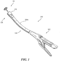
- FIGS. 1-13 illustrate a tiltable anvil assembly 10 which is suitable for use with a surgical stapling device 100 for performing surgical procedures, such as, for example, circular anastomoses of hollow tissue organs and hemorrhoid surgeries.
- surgical stapling device 100 includes a proximal handle assembly 102, an elongated central body portion 104 including a curved elongated outer tube 104a, and a distal head portion 106.
- body portion 104 and distal head portion 106 may be varied to suit a particular surgical procedure.
- Detailed descriptions of surgical stapler 100 are disclosed in commonly owned U.S. Pat. Nos. 7,364,060 and 7,303,106 ("the '060 Patent” and “the '106 Patent”).
- anvil assembly 10 includes a head assembly 12, a center rod assembly 14, and a sleeve member 15.
- Sleeve member 15 is configured to reposition an anastomosis donut and/or other tissue or obstruction (not shown) about center rod assembly 14 following the firing of surgical stapling device 100 to allow head assembly 12 to pivot relative to center rod assembly 14 without pinching the anastomosis donut between head assembly 12 and center rod assembly 14 as described in further detail below.
- an anastomosis donut is the tissue severed from the anastomosis site by an annular knife of a circular stapling device during an anastomosis procedure using a circular stapling device.
- head assembly 12 includes a post 16, a housing 18, a backup member or plate 20, a cutting ring 22, a cutting ring cover 23, an anvil plate 24, a cam latch member 26, and a retainer member 27.
- post 16 is monolithically formed with and centrally positioned within head 18.
- post 16 and head 18 may be formed as separate components that are joined using, adhesives, welding or any other suitable method.
- post 16 includes a pair of nubs 16a ( FIG. 8 ) configured to engage anvil center rod assembly 14 to prevent counter-clockwise rotation of head assembly 12 relative to anvil center rod assembly 14.
- Anvil plate 24 is supported in an outer annular recess 28 ( FIG.
- housing 18 includes a plurality of staple deforming pockets 30 for receiving and deforming staples (not shown).
- At least one tab 24a extends radially outwardly from anvil plate 24 and is received within a cutout 32 formed in an outer rim of housing 18.
- Tab 24a and cutout 32 function to align or properly position anvil plate 24 within annular recess 28 of housing 18.
- backup plate 20 includes a central opening 34 which is positioned about post 16 within an inner annular recess 36 of housing 18 between post 16 and outer annular recess 28.
- Backup plate 20 includes a raised platform 20a.
- Cutting ring 22 includes an opening 22a having a configuration substantially the same as platform 20a.
- cutting ring 22 is formed from polyethylene, or other suitable plastic, and is fixedly secured to backup plate 20 using, for example, an adhesive, to form a backup plate/cutting ring assembly.
- Backup plate 20 is formed from a hard material, e.g., a metal. Alternately other materials of construction may be used to construct backup plate 20 and cutting ring 22. Further, backup plate 20 and cutting ring 22, in the alternative, may be formed as a single or unitary structure.
- a cutting ring cover 23 may be secured to an outwardly facing or proximal surface 40 of cutting ring 22 using, for example, an adhesive.
- Cutting ring 22 and backup plate 20 are slidably mounted about post 16.
- Backup plate 20 includes a pair of inwardly extending fingers 38 which will be described in further detail below.
- Retainer member 27 is positioned in inner annular recess 36 between backup plate 20 and a back wall 18a of housing 18 and prevents backup plate 20 and cutting ring 22 from moving or being pushed into inner annular recess 36 of housing 18 until a predetermined force sufficient to deform tabs 27a has been applied to the backup plate/cutting ring assembly.
- the predetermined force may be close to but is less than the force applied by an annular cutting blade of a surgical stapling device when it engages, for example, the cutting ring of anvil assembly 10.
- backup plate 20 is urged into inner annular recess 36 and compresses tabs 27a of retainer member 27.
- Anvil center rod assembly 14 includes a center rod 52, a plunger 54, and plunger spring 56.
- a first end of center rod 52 has a pair of arms 59 which define a cavity 59a.
- Each arm 59 has a transverse throughbore 58 which is aligned with a central longitudinal axis of center rod 52.
- Post 16 of anvil head assembly 12 is dimensioned to be positioned within cavity 59a and includes a transverse throughbore 60.
- a pivot member 62 pivotably secures post 16 to center rod 52 via throughbores 58 and 60 such that anvil head assembly 12 is pivotably mounted to anvil center rod assembly 14.
- cam latch member 26 includes a body 26a having a throughbore 26b. Throughbore 26b is dimensioned to receive pivot member 62 such that cam latch member 26 is pivotally mounted within transverse slot 72 ( FIG. 3 ) of post 16 about pivot member 62. As shown in FIG. 4 , cam latch member 26 includes a first body portion 26c which extends partially from slot 72 ( FIG. 3 ) of post 16 and is positioned to be engaged by finger 66 of plunger 54. Cam latch member 26 also includes an edge 26f which is urged into engagement with an inner periphery of backup plate 20 ( FIG. 10 ) by finger 66 of plunger 54 when anvil head 12 is in the non-tilted or operative position.
- Cam latch member 26 further includes a connector portion 26g which define a throughbore 26h dimensioned to receive a pivot member 94 ( FIG. 6 ) of sleeve member 15 such that cam latch member 26 is pivotally secured to sleeve member 15.
- cam latch member 26 and sleeve member 15 may be connected by a pivot member (not shown) extending from connector portion 26g of cam latch member 26 into engagement with an opening (not shown) formed in sleeve member 15.
- plunger 54 is slidably positioned in a bore 64 formed in the first end of center rod 52.
- Plunger 54 includes an engagement finger 66 which is offset from the pivot axis of anvil head assembly 12 and is biased into engagement with an edge 26c of cam latch member 26.
- engagement of finger 66 with edge 26c of cam latch member 26 presses edge 26f against an inner periphery of back plate 20 and post 16 to urge anvil head assembly 12 to the pivoted or tilted position ( FIG. 12 ) on center rod 52.
- fingers 38 formed on backup plate 20 are positioned adjacent top surface 52a and protrusions 52b of center rod 52 to prevent anvil head assembly 12 from pivoting about pivot member 62 ( FIG. 7 ).
- backup plate 20 and cutting ring 22 are pushed into inner annular recess 36 of housing 18 about post 16, in the direction indicated by arrow "A" in FIG. 11 , by a knife blade (not shown).
- fingers 38 move into annular recess 36 away from top surface 52a and protrusions 52b of center rod 52 to permit plunger 54 ( FIG. 11 ) to pivot anvil head assembly 12 about pivot member 62.
- Retainer member 27 prevents inadvertent or premature movement of backup plate 20 into inner annular recess 36 to prevent premature or inadvertent tilting of anvil head assembly 12.
- a second end of center rod 52 includes a bore 80 defined by a plurality of flexible arms 82.
- Flexible arms 82 each include an opening 82a dimensioned to receive a projection formed on or connected to a removable trocar (not shown) or the like.
- the distal ends of each of flexible arms 82 include an internal shoulder 84 ( FIG. 10 ) dimensioned to releasably engage an anvil retainer (not shown) of a surgical stapling device 100 ( FIG. 1 ) to secure anvil assembly 10 to surgical stapling device 100.
- a plurality of splines 86 are formed about center rod 52. Splines 86 function to align anvil assembly 10 with the staple holding portion of surgical stapling device 100.
- sleeve member 15 includes a sleeve body 90 and a flange 92 extending distally from sleeve body 90.
- Sleeve body 90 is substantially tubular and is configured to be received about a distal end of center rod 52 ( FIG. 7 ) of center rod assembly 14 and to extend across the tissue gap defined between anvil plate 24 and a distal end of shell assembly 108 ( FIG. 1 ).
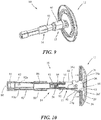
- Sleeve body 90 is sized and dimensioned to slide proximally, as indicated by arrows "C" in FIG. 13 , from a distal-most first position on center rod 52 when anvil assembly 10 is in the first or operable position ( FIG. 9 ) to a proximal position on center rod 52 ( FIG. 13 ) as head assembly 12 pivots relative to anvil center rod assembly 14.
- Sleeve body 90 optionally includes annular lips 90a, 90b formed on proximal and distal ends, respectively. Annular lips 90a, 90b are configured to maintain the anastomosis donut and/or other tissue or obstruction (not shown) about sleeve body 90 as sleeve body 90 is moved proximally about center rod 52 during pivoting of head assembly 12 from the operable position to the tilted position.
- the first and/or second sections of the tissue being joined may be secured to anvil assembly 10 using a purse string suture(s) (not shown).
- the purse string suture(s) facilitate positioning and securing of the anastomosis donut about sleeve body 90.
- Sleeve body 90 defines notch 91 configured to accommodate post 16 and cam latch member 26 ( FIG. 3 ) of head assembly 12 when sleeve body 90 is in the first, distal-most position ( FIG. 9 ).
- Sleeve body 90 further defines a longitudinal slot 93 configured to accommodate finger 66 of plunger 54 of anvil center rod assembly 14 when sleeve body 90 is in the first, distal-most position ( FIG. 9 ).
- Flange 92 extends distally from sleeve body 90 and engages cam latch member 26 of head assembly 12.
- a first end 92a of flange 92 forms a living hinge with sleeve body 90 to permit flexing of flange 92 relative to sleeve body 90.
- a second end 92b of flange 92 is pivotally secured to connector portion 26g ( FIG. 4 ) of cam latch member 26 of head assembly 12.
- flange 92 includes a pivot member 94 which is pivotally received within throughbore 26h formed in connector portion 26g of cam latch member 26.
- cam latch member 26 may instead include a pivot member (not shown) configured for reception within an opening (not shown) defined by flange 92 of sleeve body 90.
- Flange 92 is slidably supported adjacent center rod 52 between sleeve member 15 and cam latch member 26 as cam latch member 26 is pivoted by finger 66 of plunger 54 during pivoting of head assembly 12 from the first position ( FIG. 9 ) to the second position ( FIG. 12 ).
- the connection between connector portion 26g and flange 92 results in sleeve body 90 moving proximally, as indicated by arrows "C" in FIG.
- proximal movement of sleeve body 90 about center rod 52 relocates an anastomosis donut and/or other tissue or obstruction (not shown) formed during the anastomosis procedure to prevent pinching of the anastomosis donut, tissue and/or obstruction by head assembly 12 as head assembly 12 is pivoted to a tilted position ( FIG. 12 ).
- backup plate 20 when anvil assembly 12 is in the prefired non-tilted position, backup plate 20 is spaced from back wall 18a of housing 18 by retainer 27 and fingers 38 of backup plate 20 are positioned adjacent top surface 52a and protrusion 52b of center rod 52 to prevent tilting of anvil head assembly 12 about pivot member 62.
- sleeve body 90 covers the tilting mechanism, i.e., post 16 and cam latch member 26 of head assembly 12 and arms 59 of center rod 52 and pivot member 62, of tiltable anvil assembly 10.
- finger 66 of plunger 54 is urged by spring 56 into engagement with body portion 26c of cam latch member 26 and post 16 to urge cam latch member 26 and head assembly 12 in a clockwise direction about pivot member 62 such that edge 26f of cam latch member 26 engages an inner periphery 20b of backup member 20 and anvil head assembly 12 move towards the tilted position ( FIG. 12 ).
- the tilting of tiltable anvil assembly 10 facilitates insertion and/or removal of the anvil assembly to/from a hollow organ.
- FIGS. 10 and 11 when anvil assembly 10 is attached to a stapling device 100 ( FIG. 1 ) and the device is fired, a knife blade (not shown) of the stapling device engages cutting ring 22 to move cutting ring 22 ( FIG. 3 ) and backup plate 20 in the direction indicated by arrow "A" in FIG. 11 into annular recess 36 of housing 18 of anvil head assembly 12.
- deformable tabs 27a ( FIG. 3 ) of retainer 27 are deformed against back wall 18a of housing 18 and fingers 38 of backup member 20 move away from top surface 52a and protrusions 52b of center rod 52.
- anvil head assembly 12 will not immediately tilt upon firing of stapling device 100 ( FIG. 1 ) because, upon firing, anvil head assembly 12 is in an approximated position, i.e., the anvil head assembly 12 is in close alignment with shell assembly 108 ( FIG. 1 ) of surgical stapling device 100 ( FIG. 1 ). As such, the anvil head assembly 12 will begin to tilt as anvil head assembly 12 and shell assembly 108 of the stapling device 100 are unapproximated.
- cam latch member 26 As anvil head assembly 12 pivots towards its tilted position, finger 66 of plunger 54 maintains surface 26e of cam latch member 26 in contact with backup plate 20 to prevent backup plate 20 from sticking to the knife blade as the knife blade is retracted. It is noted that curved surface 26e of cam latch member is configured to eliminate any gap and ensure contact between surface 26e of cam latch member 26 and backup plate 20 to hold backup plate 20 in place during and after the knife blade is retracted such that the cutting ring and backup plate assembly stay in their correct position during tilting of anvil assembly 12.
- pivotal engagement of flange 92 of sleeve member 15 with cam latch member 26 causes sleeve body 90 to slide proximally about center rod 52 of anvil center rod assembly 14. More particularly, the pivoting of cam latch member 26 applies a proximal force to sleeve body 90 through flange 92 to effect linear movement of sleeve body 90 about center rod 52. More specifically, the pivotal engagement between flange 92 and cam latch member 26 and the living hinge formed between flange 92 and sleeve body 90 allow flange 92 to flex to translate the pivoting motion of cam latch member 26 into a proximal linear motion of sleeve body 90.
- annular lips 90a, 90b fanned on proximal and distal ends, respectively, of sleeve body 90 engage the anastomosis donut and/or other tissue or obstruction to facilitate movement of the donut/tissue/obstruction away from the tilting mechanism.
- sleeve body 90 of sleeve member 15 may instead be operably connected to post 16 of head assembly 12 of anvil assembly 10.
- sleeve body 90 of sleeve member 15 may instead be operably connected to post 16 of head assembly 12 of anvil assembly 10.
- the aspects of the present disclosure may be modified for use with any anvil assembly having an anvil head capable of being pivoted from a first, operable position, to a second, tilted position.
- anvil assembly 110 is substantially similar to anvil assembly 10 described hereinabove and will only be described as relates to the differences therebetween.
- Anvil assembly 110 includes a head assembly 112, an anvil center rod assembly 114, and a sleeve member 115.
- Head assembly 112 includes a housing 118 and a post 116.
- Post 116 includes a tab 116a and an engagement surface 116b.
- Tab 116a of post 116 is configured to be loosely received within an opening 191 formed in a sleeve body 190 of sleeve member 115 when anvil assembly 110 is in a first or operable position (the non-tilted position; see FIGS. 14 and 15 ).
- Engagement surface 116b of post 116 is configured to engage a distal end 190b of sleeve body 190 as head assembly 112 pivots relative to anvil center rod assembly 114.
- post 116 may further include a cam surface for engagement by finger 166 of plunger 154 ( FIG. 15 ).
- Sleeve member 115 includes sleeve body 190.
- Sleeve body 190 includes a substantially tubular member configured to be slidably received about a distal portion of anvil center rod assembly 114 in a sliding manner.
- sleeve member 115 may include a lip formed about one or both of proximal and distal ends 190a, 190b to facilitate retention of an anastomosis donut (not shown) about sleeve body 190.
- sleeve body 190 defines an opening 191 adjacent a distal end configured to selectively receive tab 116a of post 116 of head assembly 112.
- a distal end 190b of sleeve body 190 is configured to be engaged by engagement portion 116b of post 116 of head assembly 112 during pivoting of head assembly 112 from the first or operable position ( FIGS. 14 and 15 ) to a second or tilted position ( FIGS. 17 and 18 ). It is envisioned that engagement portion 116b of post 116 may be shaped as a cam surface.
- head assembly 112 of anvil assembly 110 is configured to pivot relative to anvil center rod assembly 114.
- tab 116a formed on post 116 of head assembly 112 is withdrawn from within opening 191 formed in sleeve body 190 of sleeve assembly 115.
- engagement surface 116b of post 116 engages distal end 190b of sleeve body 190.
- Engagement of sleeve body 190 by engagement surface 116b of post 116 moves sleeve body 190 in a proximal direction.
- an anastomosis donut (not shown) received about sleeve body 190 is moved proximally away from head assembly 112, to prevent pinching of the anastomosis donut and/or other tissue or obstruction between head assembly 112 and anvil center rod assembly 114 as head assembly 112 is pivoted to the tilted position.
- anvil assembly 210 is substantially similar to anvil assemblies 10 and 110 described hereinabove, and therefore will only be described as relates to the differences therebetween.
- Anvil assembly 210 includes a head assembly 212 and an anvil center rod assembly 214.
- anvil assembly 210 may be modified for use with either of the above disclosed sleeve members 15 ( FIG. 6 ), 115 ( FIG. 16 ).
- Head assembly 212 includes a housing 218, a post 216, and a cam latch member 226. Post 216 and cam latch member 226 may be integrally formed.
- Anvil center rod assembly 214 includes a center rod 252, a plunger 254, and plunger spring 256. Head assembly 212 is pivotally secured to center rod 252 by a pivot pin 262 which is received within a transverse throughbore (not shown) defined by post 216 and a pair of arms 259 of center rod 252.
- Cam latch member 226 defines a bore 258 which also receives pivot pin 262 to pivotally secure cam latch member 226 about pivot pin 262.
- Transverse throughbore 258 is offset, i.e., laterally spaced, relative to a central longitudinal axis "x" of center rod 252, as indicated by reference character “y” in FIG. 19 .
- the distance between pivot pin 262 and a finger 266 of plunger 254, as indicated by reference character “z” in FIG. 1 9 is increased.
- Increasing the distance between pivot pin 262 and plunger 254 increases the tilting torque applied to head assembly 212 by plunger 254 without increasing the outer diameter of center rod 252.
- Increasing the tilting torque applied to head assembly 212 by plunger 254 increases the head tilting performance of anvil assembly 210.
- pivot pin 262 permits the pivoting of head assembly 212 relative to anvil center rod assembly 214 when tissue or other obstruction disposed between head assembly 212 and anvil center rod assembly 214 might otherwise prevent head assembly 212 from pivoting relative to center rod assembly 214.
- Anvil assembly 210 operates in a similar manner to anvil assemblies 10 and 110, described hereinabove.
- engagement of a finger 266 of plunger 254 with cam latch member 226 rotates cam latch member 226 within housing 218 such that cam latch member 226 engages backup plate 220 to hold backup plate 220 in place as a knife blade (not shown) of surgical stapling device 10 ( FIG. 1 ) is retracted.
- Finger 266 of plunger 254 also engages post 216 of head assembly 212 to cause pivoting of head assembly 212 relative to anvil center rod assembly 214 as head assembly 212 is moved away from shell assembly 108 ( FIG. 1 ) of surgical stapling device 10 ( FIG. 1 ).
- an outer diameter of center rod 252 may be increased to accommodate a plunger (not shown) having a finger (not shown) that is spaced further from longitudinal axis "x" to increase the distance between pivot pin 262 and the finger of the plunger, thereby increasing the tilting torque applied by the finger to head assembly 212.
Landscapes
- Health & Medical Sciences (AREA)
- Surgery (AREA)
- Life Sciences & Earth Sciences (AREA)
- Medical Informatics (AREA)
- Nuclear Medicine, Radiotherapy & Molecular Imaging (AREA)
- Engineering & Computer Science (AREA)
- Biomedical Technology (AREA)
- Heart & Thoracic Surgery (AREA)
- Molecular Biology (AREA)
- Animal Behavior & Ethology (AREA)
- General Health & Medical Sciences (AREA)
- Public Health (AREA)
- Veterinary Medicine (AREA)
- Physiology (AREA)
- Surgical Instruments (AREA)
- Forging (AREA)
Claims (7)
- Ambossanordnung (110), die Folgendes umfasst:eine Ambossmittelstangenanordnung (114);eine Kopfanordnung (112), die an der Ambossmittelstangenanordnung von einer Betriebsposition in eine geneigte Position schwenkbar befestigt ist; undein Hülsenelement (115), das um die Ambossmittelstangenanordnung verschiebbar eingerichtet ist, wobei das Hülsenelement mit der Kopfanordnung derart verknüpft ist, dass eine Bewegung der Kopfanordnung von der Betriebsposition zu der geneigten Position eine proximale Bewegung des Hülsenelements um die Ambossmittelstangenanordnung bewirkt,wobei die Ambosskopfanordnung einen Stift (116) beinhaltet, der an der Ambossmittelstangenanordnung schwenkbar befestigt ist, wobei das Hülsenelement mit dem Stift betriebsfähig im Eingriff steht,wobei das Hülsenelement betriebsfähig positioniert ist, um durch die Kopfanordnung im Eingriff zu stehen, während die Kopfanordnung von der Betriebsposition in die geneigte Position geschwenkt wird,wobei der Stift (116) eine Lasche (116a) beinhaltet, die konfiguriert ist, um innen in einer Öffnung (191) aufgenommen zu werden, die durch einen Hülsenkörper (190) des Hülsenelements (115) ausgebildet ist, wenn sich die Kopfanordnung (110) in der Betriebsposition befindet, undwobei die Lasche (116a), die an dem Stift (116) der Kopfanordnung (112) ausgebildet ist, konfiguriert ist, um von innen aus der Öffnung (191), die in dem Hülsenkörper (190) des Hülsenelements (115) ausgebildet ist, herausgezogen zu werden, während die Kopfanordnung (112) in die geneigte Position schwenkt.
- Ambossanordnung nach Anspruch 1, wobei die Kopfanordnung ferner eine Stützplatte (20) beinhaltet.
- Ambossanordnung nach Anspruch 2, wobei die Stützplatte positioniert ist, um eine Schwenkbewegung der Kopfanordnung von der Betriebsposition in die geneigte Position vor einem Feuern einer chirurgischen Klammervorrichtung zu verhindern.
- Ambossanordnung nach Anspruch 3, wobei die Stützplatte in eine zweite Position beweglich ist, um die Schwenkbewegung der Kopfanordnung in Bezug auf die Ambossmittelstange von der Betriebsposition in die geneigte Position zu ermöglichen.
- Ambossanordnung nach einem der vorhergehenden Ansprüche, wobei das Hülsenelement positioniert ist, um durch den Stift im Eingriff zu stehen, während die Kopfanordnung von der Betriebsposition in die geneigte Position geschwenkt wird.
- Ambossanordnung nach einem der vorhergehenden Ansprüche, wobei die Kopfanordnung an der Ambossmittelstange um einen Bolzen (62) schwenkbar befestigt ist, wobei der Bolzen von der Längsachse der Ambossmittelstange versetzt ist.
- Ambossanordnung nach einem der vorhergehenden Ansprüche, wobei der Hülsenkörper rohrförmig ist.
Applications Claiming Priority (2)
| Application Number | Priority Date | Filing Date | Title |
|---|---|---|---|
| US14/023,694 US9693773B2 (en) | 2013-09-11 | 2013-09-11 | Anvil assembly with sliding sleeve |
| EP14184195.7A EP2851011B1 (de) | 2013-09-11 | 2014-09-10 | Ambossanordnung mit Schiebehülse |
Related Parent Applications (1)
| Application Number | Title | Priority Date | Filing Date |
|---|---|---|---|
| EP14184195.7A Division EP2851011B1 (de) | 2013-09-11 | 2014-09-10 | Ambossanordnung mit Schiebehülse |
Publications (2)
| Publication Number | Publication Date |
|---|---|
| EP3120784A1 EP3120784A1 (de) | 2017-01-25 |
| EP3120784B1 true EP3120784B1 (de) | 2021-10-27 |
Family
ID=51518622
Family Applications (2)
| Application Number | Title | Priority Date | Filing Date |
|---|---|---|---|
| EP16174842.1A Active EP3120784B1 (de) | 2013-09-11 | 2014-09-10 | Ambossanordnung mit schiebehülse |
| EP14184195.7A Active EP2851011B1 (de) | 2013-09-11 | 2014-09-10 | Ambossanordnung mit Schiebehülse |
Family Applications After (1)
| Application Number | Title | Priority Date | Filing Date |
|---|---|---|---|
| EP14184195.7A Active EP2851011B1 (de) | 2013-09-11 | 2014-09-10 | Ambossanordnung mit Schiebehülse |
Country Status (7)
| Country | Link |
|---|---|
| US (2) | US9693773B2 (de) |
| EP (2) | EP3120784B1 (de) |
| JP (1) | JP2015054238A (de) |
| CN (1) | CN104414700A (de) |
| AU (1) | AU2014210642B2 (de) |
| CA (1) | CA2860506A1 (de) |
| ES (2) | ES2586636T3 (de) |
Families Citing this family (53)
| Publication number | Priority date | Publication date | Assignee | Title |
|---|---|---|---|---|
| US10213205B2 (en) * | 2012-07-06 | 2019-02-26 | Covidien Lp | T-slot tilt anvil for circular stapling instrument |
| US9668740B2 (en) * | 2013-06-14 | 2017-06-06 | Covidien Lp | Anvil assembly with sliding sleeve |
| US9693773B2 (en) | 2013-09-11 | 2017-07-04 | Covidien Lp | Anvil assembly with sliding sleeve |
| DK3228254T3 (da) | 2014-02-21 | 2020-03-23 | 3Dintegrated Aps | Sæt omfattende et kirurgisk instrument |
| USD734469S1 (en) * | 2014-03-27 | 2015-07-14 | Covidien Lp | Handle for medical treatment device |
| USD736919S1 (en) * | 2014-05-06 | 2015-08-18 | Benvenue Medical, Inc. | Handle for a medical delivery device |
| US9730694B2 (en) * | 2014-07-01 | 2017-08-15 | Covidien Lp | Loading unit including shipping assembly |
| US10426480B2 (en) * | 2015-04-29 | 2019-10-01 | Covidien Lp | Cutting ring assembly with rigid cutting member |
| US9987001B2 (en) | 2015-06-12 | 2018-06-05 | Covidien Lp | Surgical anastomosis apparatus |
| US10111668B2 (en) | 2015-07-02 | 2018-10-30 | Covidien Lp | Anvil assembly with snap backup ring |
| JP6776327B2 (ja) | 2015-07-21 | 2020-10-28 | スリーディインテグレイテッド アーペーエス3Dintegrated Aps | カニューレアセンブリキット、套管針アセンブリキット、スリーブアセンブリ、低侵襲性手術システム及び方法 |
| US11020144B2 (en) | 2015-07-21 | 2021-06-01 | 3Dintegrated Aps | Minimally invasive surgery system |
| DK178899B1 (en) | 2015-10-09 | 2017-05-08 | 3Dintegrated Aps | A depiction system |
| ES2821891T3 (es) * | 2015-12-07 | 2021-04-28 | Covidien Lp | Conjunto de yunque y sistema de suministro |
| JPWO2017203682A1 (ja) * | 2016-05-27 | 2019-04-04 | オリンパス株式会社 | 医療用ステープラ |
| GB201611306D0 (en) | 2016-06-29 | 2016-08-10 | Norwegian Univ Of Science And Tech (Ntnu) | Surgical stapler and a method of stapling tissue |
| US11452522B2 (en) * | 2016-08-15 | 2022-09-27 | Covidien Lp | Circular stapling device with articulating anvil retainer assembly |
| US11241232B2 (en) * | 2017-01-24 | 2022-02-08 | Covidien Lp | Surgical stapling device with resettable anvil assembly |
| EP3600078B1 (de) * | 2017-03-23 | 2022-06-22 | Covidien LP | Kreisförmige klammervorrichtung mit ausrichtungssplines |
| US10828026B2 (en) * | 2017-08-08 | 2020-11-10 | Covidien Lp | Tiltable anvil assembly |
| US11589871B2 (en) * | 2017-11-10 | 2023-02-28 | Cilag Gmbh International | Laparoscopic stapler with flippable housing assembly and flippable anvil assembly |
| RU183782U1 (ru) * | 2018-01-09 | 2018-10-02 | Государственное бюджетное учреждение здравоохранения города Москвы Научно-исследовательский институт скорой помощи имени Н.В. Склифосовского Департамента здравоохранения г. Москвы | Циркулярный сшивающий аппарат для наложения кишечно-пищеводного анастомоза |
| US11497501B2 (en) * | 2018-03-26 | 2022-11-15 | Covidien Lp | Circular stapling device with A-frame splines |
| US10881411B2 (en) * | 2018-03-28 | 2021-01-05 | Covidien Lp | Surgical anvil assemblies for surgical stapling instruments |
| US11564691B2 (en) | 2018-08-24 | 2023-01-31 | Covidien Lp | Powered circular stapling device |
| US20220061849A1 (en) * | 2018-12-06 | 2022-03-03 | Covidien Lp | Anvil assembly with improved cut ring assembly |
| CA3139541A1 (en) | 2019-05-31 | 2020-12-03 | Covidien Lp | Circular stapling device |
| US11730481B2 (en) | 2020-01-06 | 2023-08-22 | Covidien Lp | Assemblies for retaining a trocar assembly |
| US11911038B2 (en) | 2020-01-13 | 2024-02-27 | Covidien Lp | Cut optimization for excessive tissue conditions |
| US11523828B2 (en) | 2020-01-28 | 2022-12-13 | Covidien Lp | Sealed reload assembly for stapling device |
| US11622767B2 (en) | 2020-02-19 | 2023-04-11 | Covidien Lp | Sealed trocar assembly for stapling device |
| US11779343B2 (en) | 2020-02-26 | 2023-10-10 | Covidien Lp | Staple reload assembly with releasable knife |
| US11653925B2 (en) | 2020-05-21 | 2023-05-23 | Covidien Lp | Tissue relaxation monitoring for optimized tissue stapling |
| US11547405B2 (en) | 2020-05-22 | 2023-01-10 | Covidien Lp | Surgical stapling device |
| US11553921B2 (en) | 2020-07-15 | 2023-01-17 | Covidien Lp | Surgical stapling device with flexible shaft |
| US11627966B2 (en) | 2020-08-26 | 2023-04-18 | Covidien Lp | Surgical stapling device |
| US11801054B2 (en) | 2020-09-22 | 2023-10-31 | Covidien Lp | Surgical stapler with oval tool assembly |
| US11712509B2 (en) | 2020-10-02 | 2023-08-01 | Covidien Lp | Seal assembly for circular stapling instrument |
| US11627967B2 (en) | 2020-11-23 | 2023-04-18 | Covidien Lp | Trans-anastomotic insertion device |
| EP4262580B1 (de) | 2020-12-15 | 2025-10-08 | Covidien LP | Chirurgisches klammergerät mit drehbarem nockenelement |
| US11877750B2 (en) | 2021-01-21 | 2024-01-23 | Covidien Lp | Surgical stapler with powered and manual functions |
| US11986187B2 (en) | 2021-01-29 | 2024-05-21 | Covidien Lp | Circular stapling device with integrated visualization device |
| US11786241B2 (en) | 2021-02-16 | 2023-10-17 | Covidien Lp | Surgical stapling device including a hydraulic staple formation mechanism |
| US11553920B2 (en) | 2021-05-03 | 2023-01-17 | Covidien Lp | Trocar retainer assembly for surgical stapler |
| US11490894B1 (en) | 2021-05-12 | 2022-11-08 | Covidien Lp | Surgical device with grease filter |
| US11642131B2 (en) | 2021-05-17 | 2023-05-09 | Covidien Lp | Devices and methods for shortening a rectal stump during a lower anterior resection procedure |
| US12357312B2 (en) | 2021-05-24 | 2025-07-15 | Covidien Lp | Anvil and delivery system assembly with automatic retaining suture release |
| US11612400B2 (en) | 2021-05-24 | 2023-03-28 | Covidien Lp | Trocar assembly with bearing assembly for load sharing |
| US12458357B2 (en) | 2021-06-09 | 2025-11-04 | Covidien Lp | Retractable trocar for circular stapling instruments |
| US11737759B2 (en) | 2021-08-05 | 2023-08-29 | Covidien Lp | Surgical stapling device accommodating prolapsed tissue |
| US11883028B2 (en) | 2021-09-08 | 2024-01-30 | Covidien Lp | Systems and methods for post-operative anastomotic leak detection |
| US11717299B2 (en) | 2021-10-12 | 2023-08-08 | Covidien Lp | Surgical stapling device with probiotics |
| US12213674B2 (en) | 2021-12-08 | 2025-02-04 | Covidien Lp | Determination of premature staple ejection |
Family Cites Families (300)
| Publication number | Priority date | Publication date | Assignee | Title |
|---|---|---|---|---|
| CA908529A (en) | 1972-08-29 | V. Astafiev Georgy | Surgical instrument for suturing hollow organs in infants | |
| DE1057729B (de) | 1954-03-29 | 1959-05-21 | Lameris Instr N V | Chirurgische Vorrichtung zum Verbinden zweier Darmteile |
| CA736256A (en) | 1962-08-27 | 1966-06-14 | S. Kasoolin Viacheslav | Instrument for suturing esophagus to intestine or stomach |
| FR1461464A (fr) | 1965-08-20 | 1966-02-25 | Niiex Khirurgicheskoi Apparatu | Appareil chirurgical de suture des organes |
| CH470170A (de) | 1968-02-02 | 1969-03-31 | Vnii Khirurgicheskoi Apparatur | Gerät zum Anbringen von Rundanastomosen |
| US3638652A (en) | 1970-06-01 | 1972-02-01 | James L Kelley | Surgical instrument for intraluminal anastomosis |
| US3771526A (en) | 1972-02-07 | 1973-11-13 | P Rudie | Anastomosis clamp |
| US4603693A (en) | 1977-05-26 | 1986-08-05 | United States Surgical Corporation | Instrument for circular surgical stapling of hollow body organs and disposable cartridge therefor |
| US4573468A (en) | 1977-05-26 | 1986-03-04 | United States Surgical Corporation | Hollow body organ stapling instrument and disposable cartridge employing relief vents |
| US4304236A (en) | 1977-05-26 | 1981-12-08 | United States Surgical Corporation | Stapling instrument having an anvil-carrying part of particular geometric shape |
| NL7711347A (en) | 1977-10-17 | 1979-04-19 | Carl Robert Erik Daantje | Stapling instrument for joining intestine ends - has head coupling rod in two parts screwing together with hand grip |
| US4207898A (en) | 1978-03-27 | 1980-06-17 | Senco Products, Inc. | Intralumenal anastomosis surgical stapling instrument |
| US4198982A (en) | 1978-03-31 | 1980-04-22 | Memorial Hospital For Cancer And Allied Diseases | Surgical stapling instrument and method |
| DE2947107A1 (de) | 1978-12-07 | 1980-06-26 | United States Surgical Corp | Genau fluchtende patrone und instrument zum klammern von anastomosen |
| SU1088712A1 (ru) | 1979-11-14 | 1984-04-30 | Всесоюзный научно-исследовательский и испытательный институт медицинской техники | Аппарат дл циркул рного сшивани кровеносных сосудов |
| AU534210B2 (en) | 1980-02-05 | 1984-01-12 | United States Surgical Corporation | Surgical staples |
| US4319576A (en) | 1980-02-26 | 1982-03-16 | Senco Products, Inc. | Intralumenal anastomosis surgical stapling instrument |
| US4289133A (en) | 1980-02-28 | 1981-09-15 | Senco Products, Inc. | Cut-through backup washer for the scalpel of an intraluminal surgical stapling instrument |
| US4606343A (en) | 1980-08-18 | 1986-08-19 | United States Surgical Corporation | Self-powered surgical fastening instrument |
| US4351466A (en) | 1980-10-16 | 1982-09-28 | United States Surgical Corporation | Disposable instrument for surgical fastening |
| US4379457A (en) | 1981-02-17 | 1983-04-12 | United States Surgical Corporation | Indicator for surgical stapler |
| US4476863A (en) | 1981-03-09 | 1984-10-16 | Kanshin Nikolai N | Surgical instrument for establishing circular coloanastomoses |
| US4632290A (en) | 1981-08-17 | 1986-12-30 | United States Surgical Corporation | Surgical stapler apparatus |
| US4576167A (en) | 1981-09-03 | 1986-03-18 | United States Surgical Corporation | Surgical stapler apparatus with curved shaft |
| SU1114405A1 (ru) | 1982-02-23 | 1984-09-23 | Всесоюзный научно-исследовательский и испытательный институт медицинской техники | Хирургический сшивающий аппарат дл наложени компрессионных анастомозов на органы пищеварительного тракта |
| US4473077A (en) | 1982-05-28 | 1984-09-25 | United States Surgical Corporation | Surgical stapler apparatus with flexible shaft |
| US4485817A (en) | 1982-05-28 | 1984-12-04 | United States Surgical Corporation | Surgical stapler apparatus with flexible shaft |
| US4488523A (en) | 1982-09-24 | 1984-12-18 | United States Surgical Corporation | Flexible, hydraulically actuated device for applying surgical fasteners |
| DE3301713A1 (de) | 1983-01-20 | 1984-07-26 | Horst Dr. 3004 Isernhagen Ziegler | Chirurgisches klammernahtgeraet zur herstellung zirkulaerer verbindungen |
| US4592354A (en) | 1983-10-11 | 1986-06-03 | Senmed, Inc. | Tissue retention spool for intraluminal anastomotic surgical stapling instrument and methods |
| US4505414A (en) | 1983-10-12 | 1985-03-19 | Filipi Charles J | Expandable anvil surgical stapler |
| US4550870A (en) | 1983-10-13 | 1985-11-05 | Alchemia Ltd. Partnership | Stapling device |
| IT1173284B (it) | 1984-02-16 | 1987-06-18 | Riccardo Rosati | Macchina suturatrice meccanica circolare |
| US4667673A (en) | 1984-03-12 | 1987-05-26 | American Cyanamid Company | Anastomotic device applicator and method |
| US4671445A (en) | 1984-08-09 | 1987-06-09 | Baxter Travenol Laboratories, Inc. | Flexible surgical stapler assembly |
| US4754909A (en) | 1984-08-09 | 1988-07-05 | Barker John M | Flexible stapler |
| US4703887A (en) | 1985-01-28 | 1987-11-03 | Ethicon, Inc. | Collapsible purse string aid for use with intraluminal stapling device |
| US4665917A (en) | 1985-01-28 | 1987-05-19 | Ethicon, Inc. | Tissue gripper for use with intraluminal stapling device |
| AU582625B2 (en) | 1985-01-28 | 1989-04-06 | Ethicon Inc. | Tissue gripper for use with intraluminal stapling device |
| JPS635697Y2 (de) | 1985-04-04 | 1988-02-17 | ||
| JPS62140776A (ja) | 1985-12-16 | 1987-06-24 | 海老原 代師行 | ステ−プラ |
| US4700703A (en) | 1986-03-27 | 1987-10-20 | Semion Resnick | Cartridge assembly for a surgical stapling instrument |
| US4903697A (en) | 1986-03-27 | 1990-02-27 | Semion Resnick | Cartridge assembly for a surgical stapling instrument |
| AU7286587A (en) | 1986-04-21 | 1987-11-24 | Globe Control Finanzaktiengesellschaft | Anastomosis process and device |
| US4893622A (en) | 1986-10-17 | 1990-01-16 | United States Surgical Corporation | Method of stapling tubular body organs |
| US4752024A (en) | 1986-10-17 | 1988-06-21 | Green David T | Surgical fastener and surgical stapling apparatus |
| US4917114A (en) | 1986-10-17 | 1990-04-17 | United States Surgical Corporation | Surgical fastener and surgical stapling apparatus |
| US4776506A (en) | 1986-11-13 | 1988-10-11 | United States Surgical Corporation | Surgical stapler apparatus |
| US4873977A (en) | 1987-02-11 | 1989-10-17 | Odis L. Avant | Stapling method and apparatus for vesicle-urethral re-anastomosis following retropubic prostatectomy and other tubular anastomosis |
| US5119983A (en) | 1987-05-26 | 1992-06-09 | United States Surgical Corporation | Surgical stapler apparatus |
| US5158222A (en) | 1987-05-26 | 1992-10-27 | United States Surgical Corp. | Surgical stapler apparatus |
| US5285944A (en) | 1987-05-26 | 1994-02-15 | United States Surgical Corporation | Surgical stapler apparatus |
| SU1616624A1 (ru) | 1987-07-14 | 1990-12-30 | Предприятие П/Я А-3697 | Хирургический сшивающий аппарат |
| SU1509052A1 (ru) | 1988-01-18 | 1989-09-23 | С. А. Попов | Хирургический сшивающий аппарат |
| US4907591A (en) | 1988-03-29 | 1990-03-13 | Pfizer Hospital Products Group, Inc. | Surgical instrument for establishing compression anastomosis |
| US5005749A (en) | 1988-07-01 | 1991-04-09 | United States Surgical Corp. | Anastomosis surgical stapling instrument |
| US5193731A (en) | 1988-07-01 | 1993-03-16 | United States Surgical Corporation | Anastomosis surgical stapling instrument |
| ES2011110A6 (es) | 1988-09-02 | 1989-12-16 | Lopez Hervas Pedro | Aparato hidraulico de cuerpo flexible para anastomosis quirurgicas. |
| US5197648A (en) | 1988-11-29 | 1993-03-30 | Gingold Bruce S | Surgical stapling apparatus |
| WO1990006085A1 (en) | 1988-11-29 | 1990-06-14 | Gingold Bruce S | Surgical stapling apparatus |
| CH677728A5 (de) | 1989-10-17 | 1991-06-28 | Bieffe Medital Sa | |
| US5366462A (en) | 1990-08-28 | 1994-11-22 | Robert L. Kaster | Method of side-to-end vascular anastomotic stapling |
| US5047039A (en) | 1990-09-14 | 1991-09-10 | Odis Lynn Avant | Method and apparatus for effecting dorsal vein ligation and tubular anastomosis and laparoscopic prostatectomy |
| US5253793A (en) | 1990-09-17 | 1993-10-19 | United States Surgical Corporation | Apparatus for applying two-part surgical fasteners |
| US5104025A (en) | 1990-09-28 | 1992-04-14 | Ethicon, Inc. | Intraluminal anastomotic surgical stapler with detached anvil |
| US5042707A (en) | 1990-10-16 | 1991-08-27 | Taheri Syde A | Intravascular stapler, and method of operating same |
| CA2055943C (en) | 1990-12-06 | 2003-09-23 | Daniel P. Rodak | Surgical fastening apparatus with locking mechanism |
| US5122156A (en) | 1990-12-14 | 1992-06-16 | United States Surgical Corporation | Apparatus for securement and attachment of body organs |
| US5222963A (en) | 1991-01-17 | 1993-06-29 | Ethicon, Inc. | Pull-through circular anastomosic intraluminal stapler with absorbable fastener means |
| DE69208991T2 (de) | 1991-03-29 | 1996-07-25 | Perouse Implant Lab | Chirurgisches Klammernähgerät |
| US5221036A (en) | 1991-06-11 | 1993-06-22 | Haruo Takase | Surgical stapler |
| GR920100358A (el) | 1991-08-23 | 1993-06-07 | Ethicon Inc | Οργανο συρραφής χειρουργικής αναστομώσεως. |
| US5350104A (en) | 1991-08-23 | 1994-09-27 | Ethicon, Inc. | Sealing means for endoscopic surgical anastomosis stapling instrument |
| US5333773A (en) | 1991-08-23 | 1994-08-02 | Ethicon, Inc. | Sealing means for endoscopic surgical anastomosis stapling instrument |
| US5474223A (en) | 1991-10-18 | 1995-12-12 | United States Surgical Corporation | Surgical fastener applying apparatus |
| US5443198A (en) | 1991-10-18 | 1995-08-22 | United States Surgical Corporation | Surgical fastener applying apparatus |
| US5197649A (en) | 1991-10-29 | 1993-03-30 | The Trustees Of Columbia University In The City Of New York | Gastrointestinal endoscoptic stapler |
| US5433721A (en) | 1992-01-17 | 1995-07-18 | Ethicon, Inc. | Endoscopic instrument having a torsionally stiff drive shaft for applying fasteners to tissue |
| US5188638A (en) | 1992-02-06 | 1993-02-23 | Tzakis Andreas G | Apparatus and method for preforming anastomosis fastener securement of hollow organs |
| US5271543A (en) | 1992-02-07 | 1993-12-21 | Ethicon, Inc. | Surgical anastomosis stapling instrument with flexible support shaft and anvil adjusting mechanism |
| US5348259A (en) | 1992-02-10 | 1994-09-20 | Massachusetts Institute Of Technology | Flexible, articulable column |
| US5425738A (en) | 1992-04-08 | 1995-06-20 | American Cyanamid Company | Endoscopic anastomosis ring insertion device and method of use thereof |
| US5282810A (en) | 1992-04-08 | 1994-02-01 | American Cyanamid Company | Surgical anastomosis device |
| US5355897A (en) | 1992-04-16 | 1994-10-18 | Ethicon, Inc. | Method of performing a pyloroplasty/pylorectomy using a stapler having a shield |
| US5314435A (en) | 1992-05-19 | 1994-05-24 | United States Surgical Corporation | Anvil delivery system |
| US5344059A (en) | 1992-05-19 | 1994-09-06 | United States Surgical Corporation | Surgical apparatus and anvil delivery system therefor |
| JPH0647050A (ja) | 1992-06-04 | 1994-02-22 | Olympus Optical Co Ltd | 組織縫合結紮器 |
| US5658300A (en) | 1992-06-04 | 1997-08-19 | Olympus Optical Co., Ltd. | Tissue fixing surgical instrument, tissue-fixing device, and method of fixing tissues |
| US5360154A (en) | 1992-07-17 | 1994-11-01 | United States Surgical Corporation | Apparatus for creating partial anastomoses |
| US5330486A (en) | 1992-07-29 | 1994-07-19 | Wilk Peter J | Laparoscopic or endoscopic anastomosis technique and associated instruments |
| US5261920A (en) | 1992-08-21 | 1993-11-16 | Ethicon, Inc. | Anvil bushing for circular stapler |
| US5368215A (en) | 1992-09-08 | 1994-11-29 | United States Surgical Corporation | Surgical apparatus and detachable anvil rod therefor |
| US5309927A (en) | 1992-10-22 | 1994-05-10 | Ethicon, Inc. | Circular stapler tissue retention spring method |
| US5314436A (en) | 1992-10-30 | 1994-05-24 | Wilk Peter J | Method and apparatus for performing end-to-end anastomoses |
| US5404870A (en) | 1993-05-28 | 1995-04-11 | Ethicon, Inc. | Method of using a transanal inserter |
| US5503320A (en) | 1993-08-19 | 1996-04-02 | United States Surgical Corporation | Surgical apparatus with indicator |
| US5454825A (en) | 1993-10-01 | 1995-10-03 | United States Surgical Corporation | Circular anastomosis device with seal |
| US5437684A (en) | 1993-10-01 | 1995-08-01 | United States Surgical Corporation | Circular anastomosis device |
| US5522534A (en) | 1993-10-01 | 1996-06-04 | United States Surgical Corporation | Anvil for surgical stapler |
| US5447514A (en) | 1993-10-01 | 1995-09-05 | United States Surgical Corporation | Circular anastomosis device |
| CA2132917C (en) | 1993-10-07 | 2004-12-14 | John Charles Robertson | Circular anastomosis device |
| US5503635A (en) | 1993-11-12 | 1996-04-02 | United States Surgical Corporation | Apparatus and method for performing compressional anastomoses |
| DE4407668A1 (de) | 1994-03-09 | 1995-09-14 | Ferdinand Dr Koeckerling | Chirurgisches Anastomosenring-Setzgerät |
| US5464415A (en) | 1994-03-15 | 1995-11-07 | Chen; Te-Chuan | Sutureless intestinal anastomosis gun |
| US5860581A (en) | 1994-03-24 | 1999-01-19 | United States Surgical Corporation | Anvil for circular stapler |
| US5715987A (en) | 1994-04-05 | 1998-02-10 | Tracor Incorporated | Constant width, adjustable grip, staple apparatus and method |
| CA2147800C (en) | 1994-05-26 | 2006-07-11 | John Charles Robertson | Circular anastomosis device |
| US5881943A (en) | 1994-06-17 | 1999-03-16 | Heartport, Inc. | Surgical anastomosis apparatus and method thereof |
| US5732872A (en) | 1994-06-17 | 1998-03-31 | Heartport, Inc. | Surgical stapling instrument |
| JP3568207B2 (ja) | 1994-06-17 | 2004-09-22 | ハートポート インコーポレイテッド | 外科用ステープル打ち器具 |
| CA2146508C (en) | 1994-08-25 | 2006-11-14 | Robert H. Schnut | Anvil for circular stapler |
| US5685474A (en) | 1994-10-04 | 1997-11-11 | United States Surgical Corporation | Tactile indicator for surgical instrument |
| US5868760A (en) | 1994-12-07 | 1999-02-09 | Mcguckin, Jr.; James F. | Method and apparatus for endolumenally resectioning tissue |
| US7235089B1 (en) | 1994-12-07 | 2007-06-26 | Boston Scientific Corporation | Surgical apparatus and method |
| US5720755A (en) | 1995-01-18 | 1998-02-24 | Dakov; Pepi | Tubular suturing device and methods of use |
| US5904697A (en) | 1995-02-24 | 1999-05-18 | Heartport, Inc. | Devices and methods for performing a vascular anastomosis |
| DE19509115C2 (de) | 1995-03-16 | 1997-11-27 | Deutsche Forsch Luft Raumfahrt | Chirurgisches Gerät zum Vorbereiten einer Anastomose in minimal invasiver Operationstechnik |
| US5769841A (en) | 1995-06-13 | 1998-06-23 | Electroscope, Inc. | Electrosurgical apparatus for laparoscopic and like procedures |
| US5641111A (en) | 1995-06-28 | 1997-06-24 | Ethicon Endo-Surgery, Inc. | Surgical stapling instrument with anvil cutting guide |
| US5749896A (en) | 1995-07-18 | 1998-05-12 | Cook; Melvin S. | Staple overlap |
| US5839639A (en) | 1995-08-17 | 1998-11-24 | Lasersurge, Inc. | Collapsible anvil assembly and applicator instrument |
| US5814055A (en) | 1995-09-19 | 1998-09-29 | Ethicon Endo-Surgery, Inc. | Surgical clamping mechanism |
| US5993468A (en) | 1995-10-31 | 1999-11-30 | Oticon A/S | Method and anastomotic instrument for use when performing an end-to-side anastomosis |
| US5836503A (en) | 1996-04-22 | 1998-11-17 | United States Surgical Corporation | Insertion device for surgical apparatus |
| US6050472A (en) | 1996-04-26 | 2000-04-18 | Olympus Optical Co., Ltd. | Surgical anastomosis stapler |
| US6119913A (en) | 1996-06-14 | 2000-09-19 | Boston Scientific Corporation | Endoscopic stapler |
| US6024748A (en) | 1996-07-23 | 2000-02-15 | United States Surgical Corporation | Singleshot anastomosis instrument with detachable loading unit and method |
| US20020019642A1 (en) | 1996-07-23 | 2002-02-14 | Keith Milliman | Anastomosis instrument and method for performing same |
| US5833698A (en) | 1996-07-23 | 1998-11-10 | United States Surgical Corporation | Anastomosis instrument and method |
| US6440146B2 (en) | 1996-07-23 | 2002-08-27 | United States Surgical Corporation | Anastomosis instrument and method |
| US5855312A (en) | 1996-07-25 | 1999-01-05 | Toledano; Haviv | Flexible annular stapler for closed surgery of hollow organs |
| US6338737B1 (en) | 1997-07-17 | 2002-01-15 | Haviv Toledano | Flexible annular stapler for closed surgery of hollow organs |
| US5865361A (en) | 1997-09-23 | 1999-02-02 | United States Surgical Corporation | Surgical stapling apparatus |
| US6117148A (en) | 1997-10-17 | 2000-09-12 | Ravo; Biagio | Intraluminal anastomotic device |
| US5951576A (en) | 1998-03-02 | 1999-09-14 | Wakabayashi; Akio | End-to-side vascular anastomosing stapling device |
| US6279809B1 (en) | 1998-03-10 | 2001-08-28 | Enrico Nicolo | Circular stapler for side to end, side to side and end to side anastomosis |
| AU751697B2 (en) | 1998-05-11 | 2002-08-22 | Surgical Connections, Inc. | Devices and methods for treating e.g. urinary stress incontinence |
| US6517566B1 (en) | 1998-05-11 | 2003-02-11 | Surgical Connections, Inc. | Devices and methods for treating e.g. urinary stress incontinence |
| US6478210B2 (en) | 2000-10-25 | 2002-11-12 | Scimed Life Systems, Inc. | Method and device for full thickness resectioning of an organ |
| US6629630B2 (en) | 1998-06-19 | 2003-10-07 | Scimed Life Systems, Inc. | Non-circular resection device and endoscope |
| US6601749B2 (en) | 1998-06-19 | 2003-08-05 | Scimed Life Systems, Inc. | Multi fire full thickness resectioning device |
| US6585144B2 (en) | 1998-06-19 | 2003-07-01 | Acimed Life Systems, Inc. | Integrated surgical staple retainer for a full thickness resectioning device |
| US6126058A (en) | 1998-06-19 | 2000-10-03 | Scimed Life Systems, Inc. | Method and device for full thickness resectioning of an organ |
| DE19837258A1 (de) | 1998-08-17 | 2000-03-02 | Deutsch Zentr Luft & Raumfahrt | Vorrichtung zum Betätigen eines chirurgischen Instrumentariums zur Anastomose von Hohlorganen |
| DE19836950B4 (de) | 1998-08-17 | 2004-09-02 | Deutsches Zentrum für Luft- und Raumfahrt e.V. | Chirurgisches Instrument in Form eines Nahtklammergerätes |
| US6203553B1 (en) | 1999-09-08 | 2001-03-20 | United States Surgical | Stapling apparatus and method for heart valve replacement |
| US6102271A (en) | 1998-11-23 | 2000-08-15 | Ethicon Endo-Surgery, Inc. | Circular stapler for hemorrhoidal surgery |
| US6142933A (en) | 1998-11-23 | 2000-11-07 | Ethicon Endo-Surgery, Inc. | Anoscope for hemorrhoidal surgery |
| US6083241A (en) | 1998-11-23 | 2000-07-04 | Ethicon Endo-Surgery, Inc. | Method of use of a circular stapler for hemorrhoidal procedure |
| US6626921B2 (en) | 1999-04-16 | 2003-09-30 | Integrated Vascular Interventional Technologies, L.C. | Externally positioned anvil apparatus for cutting anastomosis |
| US6551334B2 (en) | 1999-04-16 | 2003-04-22 | Integrated Vascular Interventional Technologies, Lc | Externally directed anastomosis systems and externally positioned anastomosis fenestra cutting apparatus |
| US6743244B2 (en) | 1999-04-16 | 2004-06-01 | Integrated Vascular Interventional Technologies, L.C. | Soft anvil apparatus for cutting anastomosis fenestra |
| US6652542B2 (en) | 1999-04-16 | 2003-11-25 | Integrated Vascular Interventional Technologies, L.C. (Ivit, Lc) | External anastomosis operators and related systems for anastomosis |
| US6402008B1 (en) | 1999-04-19 | 2002-06-11 | Deborah A. Lucas | Surgical stapler assembly with interchangeable heads |
| US6068636A (en) | 1999-04-23 | 2000-05-30 | Chen; Te-Chuan | Intra-intestinal bypass gun |
| US7032798B2 (en) | 1999-06-02 | 2006-04-25 | Power Medical Interventions, Inc. | Electro-mechanical surgical device |
| US6793652B1 (en) | 1999-06-02 | 2004-09-21 | Power Medical Interventions, Inc. | Electro-mechanical surgical device |
| US6315184B1 (en) | 1999-06-02 | 2001-11-13 | Powermed, Inc. | Stapling device for use with an electromechanical driver device for use with anastomosing, stapling, and resecting instruments |
| US6491201B1 (en) | 2000-02-22 | 2002-12-10 | Power Medical Interventions, Inc. | Fluid delivery mechanism for use with anastomosing, stapling, and resecting instruments |
| US6716233B1 (en) | 1999-06-02 | 2004-04-06 | Power Medical Interventions, Inc. | Electromechanical driver and remote surgical instrument attachment having computer assisted control capabilities |
| US6981941B2 (en) | 1999-06-02 | 2006-01-03 | Power Medical Interventions | Electro-mechanical surgical device |
| US6443973B1 (en) | 1999-06-02 | 2002-09-03 | Power Medical Interventions, Inc. | Electromechanical driver device for use with anastomosing, stapling, and resecting instruments |
| US8025199B2 (en) | 2004-02-23 | 2011-09-27 | Tyco Healthcare Group Lp | Surgical cutting and stapling device |
| US6264087B1 (en) | 1999-07-12 | 2001-07-24 | Powermed, Inc. | Expanding parallel jaw device for use with an electromechanical driver device |
| EP1251786B1 (de) | 2000-01-18 | 2007-03-14 | Tyco Healthcare Group Lp | Instrument zur Anastomose |
| US6193129B1 (en) | 2000-01-24 | 2001-02-27 | Ethicon Endo-Surgery, Inc. | Cutting blade for a surgical anastomosis stapling instrument |
| HU225908B1 (en) | 2000-01-24 | 2007-12-28 | Ethicon Endo Surgery Europe | Surgical circular stapling head |
| US6533157B1 (en) | 2000-02-22 | 2003-03-18 | Power Medical Interventions, Inc. | Tissue stapling attachment for use with an electromechanical driver device |
| US6488197B1 (en) | 2000-02-22 | 2002-12-03 | Power Medical Interventions, Inc. | Fluid delivery device for use with anastomosing resecting and stapling instruments |
| US6273897B1 (en) | 2000-02-29 | 2001-08-14 | Ethicon, Inc. | Surgical bettress and surgical stapling apparatus |
| CA2646518C (en) | 2000-03-06 | 2011-01-18 | Tyco Healthcare Group Lp | Apparatus and method for performing a bypass procedure in a digestive system |
| IL139788A (en) | 2000-11-20 | 2006-10-05 | Minelu Zonnenschein | Stapler for endoscopes |
| US6592596B1 (en) | 2000-05-10 | 2003-07-15 | Scimed Life Systems, Inc. | Devices and related methods for securing a tissue fold |
| US20040267310A1 (en) | 2000-10-20 | 2004-12-30 | Racenet David C | Directionally biased staple and anvil assembly for forming the staple |
| US6821282B2 (en) | 2000-11-27 | 2004-11-23 | Scimed Life Systems, Inc. | Full thickness resection device control handle |
| US8286845B2 (en) | 2000-11-27 | 2012-10-16 | Boston Scientific Scimed, Inc. | Full thickness resection device control handle |
| US6398795B1 (en) | 2000-11-30 | 2002-06-04 | Scimed Life Systems, Inc. | Stapling and cutting in resectioning for full thickness resection devices |
| US6439446B1 (en) | 2000-12-01 | 2002-08-27 | Stephen J. Perry | Safety lockout for actuator shaft |
| US6503259B2 (en) | 2000-12-27 | 2003-01-07 | Ethicon, Inc. | Expandable anastomotic device |
| US6632237B2 (en) | 2001-01-11 | 2003-10-14 | Bio-Seal Tech, Inc. | Device and method for sealing a puncture in a blood vessel |
| DE60227235D1 (de) | 2001-01-24 | 2008-08-07 | Tyco Healthcare | Instrument und verfahren zur durchführung einer anastomose |
| AU2002242071B2 (en) | 2001-01-31 | 2006-10-19 | Rex Medical, Inc. | Apparatus and method for stapling and resectioning gastro-esophageal tissue |
| US6769590B2 (en) | 2001-04-02 | 2004-08-03 | Susan E. Vresh | Luminal anastomotic device and method |
| CA2442680C (en) * | 2001-04-03 | 2010-03-23 | Tyco Healthcare Group Lp | Surgical stapling device |
| US6632227B2 (en) | 2001-08-24 | 2003-10-14 | Scimed Life Systems, Inc. | Endoscopic resection devices |
| JP2005502421A (ja) | 2001-09-17 | 2005-01-27 | ガルシア・ビセンテ ヒレテ | 開頭手術用骨固定具 |
| US6578751B2 (en) | 2001-09-26 | 2003-06-17 | Scimed Life Systems, Inc. | Method of sequentially firing staples using springs and a rotary or linear shutter |
| US20070060952A1 (en) | 2005-09-02 | 2007-03-15 | Roby Mark S | Surgical stapling device with coated knife blade |
| US6605098B2 (en) | 2001-09-28 | 2003-08-12 | Ethicon, Inc. | Surgical device for creating an anastomosis between first and second hollow organs |
| JP4346439B2 (ja) * | 2001-10-05 | 2009-10-21 | タイコ ヘルスケア グループ エルピー | 外科的ファスナーデバイスのための傾斜トップアンビル |
| US6605078B2 (en) | 2001-11-26 | 2003-08-12 | Scimed Life Systems, Inc. | Full thickness resection device |
| DE10158246C1 (de) | 2001-11-28 | 2003-08-21 | Ethicon Endo Surgery Europe | Chirurgisches Klammersetzinstrument |
| US20030111507A1 (en) | 2001-12-14 | 2003-06-19 | George Nunez | Balloon actuator for use in a resectioning device |
| US6981979B2 (en) | 2001-12-14 | 2006-01-03 | Enrico Nicolo | Surgical anastomotic devices |
| US6905504B1 (en) | 2002-02-26 | 2005-06-14 | Cardica, Inc. | Tool for performing end-to-end anastomosis |
| US7128748B2 (en) | 2002-03-26 | 2006-10-31 | Synovis Life Technologies, Inc. | Circular stapler buttress combination |
| WO2003090631A1 (en) | 2002-04-24 | 2003-11-06 | Surgical Connections, Inc. | Resection and anastomosis devices and methods |
| EP1496805B1 (de) | 2002-04-25 | 2012-01-11 | Tyco Healthcare Group LP | Chirurgische instrumente mit elektromechanischen mikro-sensoren (mems) |
| US6685079B2 (en) | 2002-05-24 | 2004-02-03 | Scimed Life Systems, Inc. | Full thickness resectioning device |
| US7195142B2 (en) | 2003-05-30 | 2007-03-27 | Tyco Healthcare Group Lp | End-to-end anastomosis instrument and method for performing same |
| US6769594B2 (en) | 2002-05-31 | 2004-08-03 | Tyco Healthcare Group, Lp | End-to-end anastomosis instrument and method for performing same |
| ES2327768T3 (es) | 2002-06-17 | 2009-11-03 | Tyco Healthcare Group Lp | Estruturas anulares de soporte. |
| IL150855A (en) | 2002-07-22 | 2007-06-03 | Leonid Monassevitch | Intratubular anastomosis apparatus |
| WO2004032766A2 (en) | 2002-10-04 | 2004-04-22 | Tyco Healthcare Group Lp | Surgical stapling device |
| CA2500785C (en) | 2002-10-04 | 2011-04-26 | Philip C. Roy | Pneumatic powered surgical stapling device |
| US7220237B2 (en) | 2002-10-23 | 2007-05-22 | Satiety, Inc. | Method and device for use in endoscopic organ procedures |
| WO2004058078A1 (en) | 2002-12-16 | 2004-07-15 | Edrich Vascular Devices, Inc. | Multiple stapling device for narrow blood vessels |
| JP4468821B2 (ja) | 2002-12-20 | 2010-05-26 | タイコ ヘルスケア グループ リミテッド パートナーシップ | 真空補助式外科用ステープラー |
| US6852122B2 (en) | 2003-01-23 | 2005-02-08 | Cordis Corporation | Coated endovascular AAA device |
| KR100547166B1 (ko) | 2003-04-11 | 2006-01-26 | 허윤석 | 개량형 단단문합기 |
| ES2550808T3 (es) | 2003-06-20 | 2015-11-12 | Covidien Lp | Instrumento de grapado quirúrgico |
| WO2005009216A2 (en) | 2003-07-16 | 2005-02-03 | Tyco Healthcare Group, Lp | Surgical stapling device with tissue tensioner |
| US7686201B2 (en) | 2003-09-01 | 2010-03-30 | Tyco Healthcare Group Lp | Circular stapler for hemorrhoid operations |
| US7547312B2 (en) | 2003-09-17 | 2009-06-16 | Gore Enterprise Holdings, Inc. | Circular stapler buttress |
| US7309341B2 (en) | 2003-09-30 | 2007-12-18 | Ethicon Endo-Surgery, Inc. | Single lumen anastomosis applier for self-deploying fastener |
| US7364060B2 (en) | 2003-10-17 | 2008-04-29 | Tyco Healthcare Group Lp | Surgical stapling device with tiltable anvil head |
| US8590764B2 (en) | 2003-12-24 | 2013-11-26 | Boston Scientific Scimed, Inc. | Circumferential full thickness resectioning device |
| US7585306B2 (en) | 2003-12-24 | 2009-09-08 | Maquet Cardiovascular Llc | Anastomosis device, tools and methods of using |
| US7086267B2 (en) | 2004-02-18 | 2006-08-08 | Frank W. Dworak | Metal-forming die and method for manufacturing same |
| US6953138B1 (en) | 2004-02-18 | 2005-10-11 | Frank W. Dworak | Surgical stapler anvil with nested staple forming pockets |
| US7118528B1 (en) | 2004-03-16 | 2006-10-10 | Gregory Piskun | Hemorrhoids treatment method and associated instrument assembly including anoscope and cofunctioning tissue occlusion device |
| US8181840B2 (en) | 2004-03-19 | 2012-05-22 | Tyco Healthcare Group Lp | Tissue tensioner assembly and approximation mechanism for surgical stapling device |
| EP1729651B1 (de) | 2004-03-19 | 2012-12-05 | Tyco Healthcare Group LP | Ambossanordnung mit verbessertem schneidring |
| CA2566794A1 (en) | 2004-05-17 | 2005-12-08 | Datascope Investment Corp. | Surgical stapling system |
| JP4257270B2 (ja) | 2004-07-14 | 2009-04-22 | オリンパス株式会社 | 生体組織縫合方法及び生体組織縫合器 |
| US7410086B2 (en) | 2004-07-28 | 2008-08-12 | Ethicon Endo-Surgery, Inc. | Electroactive polymer-based actuation mechanism for circular stapler |
| US7182239B1 (en) | 2004-08-27 | 2007-02-27 | Myers Stephan R | Segmented introducer device for a circular surgical stapler |
| KR100646762B1 (ko) | 2004-09-10 | 2006-11-23 | 인하대학교 산학협력단 | 수술용 스테이플 및 이를 구비한 수술용 자동 문합기 |
| AU2005295811B2 (en) | 2004-10-18 | 2011-03-03 | Covidien Lp | Adhesive suture structure and methods of using the same |
| US7717313B2 (en) | 2004-10-18 | 2010-05-18 | Tyco Healthcare Group Lp | Surgical apparatus and structure for applying sprayable wound treatment material |
| US7285125B2 (en) | 2004-10-18 | 2007-10-23 | Tyco Healthcare Group Lp | Compression anastomosis device and method |
| EP2345375A1 (de) | 2004-10-18 | 2011-07-20 | Tyco Healthcare Group LP | Ringförmige Klebestruktur |
| US7938307B2 (en) | 2004-10-18 | 2011-05-10 | Tyco Healthcare Group Lp | Support structures and methods of using the same |
| US7845536B2 (en) | 2004-10-18 | 2010-12-07 | Tyco Healthcare Group Lp | Annular adhesive structure |
| EP1804682B1 (de) | 2004-10-18 | 2017-11-29 | Covidien LP | Struktur zum aufsprühen eines wundbehandlungsmaterials |
| US7455682B2 (en) | 2004-10-18 | 2008-11-25 | Tyco Healthcare Group Lp | Structure containing wound treatment material |
| ITMI20042132A1 (it) | 2004-11-05 | 2005-02-05 | Ethicon Endo Surgery Inc | Dispositivo e metodo per la terapia dell'obesita' |
| US7207168B2 (en) | 2004-11-19 | 2007-04-24 | The Schnipke Family Limited Liability Company | Apparatus and method for inserting staple drivers in a cartridge |
| US7770776B2 (en) | 2005-01-26 | 2010-08-10 | Suzhou Touchstone International Medical Science Co., Ltd | Rotatable stapling head of a surgical stapler |
| US20060201989A1 (en) | 2005-03-11 | 2006-09-14 | Ojeda Herminio F | Surgical anvil and system for deploying the same |
| US9364229B2 (en) | 2005-03-15 | 2016-06-14 | Covidien Lp | Circular anastomosis structures |
| US7717312B2 (en) | 2005-06-03 | 2010-05-18 | Tyco Healthcare Group Lp | Surgical instruments employing sensors |
| US8627995B2 (en) | 2006-05-19 | 2014-01-14 | Ethicon Endo-Sugery, Inc. | Electrically self-powered surgical instrument with cryptographic identification of interchangeable part |
| US7959050B2 (en) | 2005-07-26 | 2011-06-14 | Ethicon Endo-Surgery, Inc | Electrically self-powered surgical instrument with manual release |
| US8573462B2 (en) | 2006-05-19 | 2013-11-05 | Ethicon Endo-Surgery, Inc. | Electrical surgical instrument with optimized power supply and drive |
| US20070029363A1 (en) | 2005-08-07 | 2007-02-08 | Sergey Popov | Surgical apparatus with remote drive |
| US7401721B2 (en) | 2005-08-15 | 2008-07-22 | Tyco Healthcare Group Lp | Surgical stapling instruments including a cartridge having multiple staple sizes |
| US7398908B2 (en) | 2005-08-15 | 2008-07-15 | Tyco Healthcare Group Lp | Surgical stapling instruments including a cartridge having multiple staple sizes |
| US7407075B2 (en) | 2005-08-15 | 2008-08-05 | Tyco Healthcare Group Lp | Staple cartridge having multiple staple sizes for a surgical stapling instrument |
| US7771440B2 (en) | 2005-08-18 | 2010-08-10 | Ethicon Endo-Surgery, Inc. | Method and apparatus for endoscopically performing gastric reduction surgery in a single pass |
| US8365976B2 (en) | 2006-09-29 | 2013-02-05 | Ethicon Endo-Surgery, Inc. | Surgical staples having dissolvable, bioabsorbable or biofragmentable portions and stapling instruments for deploying the same |
| US20070194079A1 (en) | 2005-08-31 | 2007-08-23 | Hueil Joseph C | Surgical stapling device with staple drivers of different height |
| CN2868208Y (zh) | 2005-12-14 | 2007-02-14 | 苏州天臣国际医疗科技有限公司 | 设有自动保险机构的圆管型装订仪 |
| US7422138B2 (en) | 2006-02-01 | 2008-09-09 | Ethicon Endo-Surgery, Inc. | Elliptical intraluminal surgical stapler for anastomosis |
| US7793813B2 (en) | 2006-02-28 | 2010-09-14 | Tyco Healthcare Group Lp | Hub for positioning annular structure on a surgical device |
| WO2007112059A2 (en) | 2006-03-23 | 2007-10-04 | Edrich Health Technologies , Inc. | Vascular anastomotic staplers |
| US8540132B2 (en) * | 2006-05-16 | 2013-09-24 | Covidien Lp | Tilt anvil assembly |
| EP1875870B1 (de) | 2006-07-07 | 2009-12-02 | Ethicon Endo-Surgery, Inc. | Chirurgische Klammersetzvorrichtung |
| US8205782B2 (en) | 2006-07-12 | 2012-06-26 | Niti Surgical Solutions Ltd. | Compression assemblies and applicators for use therewith |
| US7527185B2 (en) | 2006-07-12 | 2009-05-05 | Niti Surgical Solutions Ltd. | Compression anastomosis ring assembly and applicator for use therewith |
| AU2007348492B9 (en) | 2007-03-07 | 2013-04-18 | Covidien Ag | Stapler for mucosectomy |
| US7673782B2 (en) | 2007-03-15 | 2010-03-09 | Ethicon Endo-Surgery, Inc. | Surgical stapling instrument having a releasable buttress material |
| US8038045B2 (en) | 2007-05-25 | 2011-10-18 | Tyco Healthcare Group Lp | Staple buttress retention system |
| US7600663B2 (en) | 2007-07-05 | 2009-10-13 | Green David T | Apparatus for stapling and incising tissue |
| US7967181B2 (en) | 2007-08-29 | 2011-06-28 | Tyco Healthcare Group Lp | Rotary knife cutting systems |
| US8011554B2 (en) | 2008-01-09 | 2011-09-06 | Tyco Healthcare Group, Lp | Raised boss for staple guide |
| US8733611B2 (en) | 2008-03-12 | 2014-05-27 | Covidien Lp | Ratcheting mechanism for surgical stapling device |
| US8020741B2 (en) | 2008-03-18 | 2011-09-20 | Barosense, Inc. | Endoscopic stapling devices and methods |
| US8231041B2 (en) | 2008-04-14 | 2012-07-31 | Tyco Healthcare Group Lp | Variable compression surgical fastener cartridge |
| JP5376380B2 (ja) | 2008-04-30 | 2013-12-25 | 学校法人自治医科大学 | 自然開口部越管腔内視鏡手術(notes)用外科手術システム |
| US8011551B2 (en) | 2008-07-01 | 2011-09-06 | Tyco Healthcare Group Lp | Retraction mechanism with clutch-less drive for use with a surgical apparatus |
| US8678264B2 (en) | 2008-07-07 | 2014-03-25 | Covidien Lp | Surgical instrument with elongated channel |
| US8109426B2 (en) | 2008-08-12 | 2012-02-07 | Tyco Healthcare Group Lp | Surgical tilt anvil assembly |
| US20100051668A1 (en) | 2008-09-03 | 2010-03-04 | Milliman Keith L | Surgical instrument with indicator |
| US8181838B2 (en) | 2008-09-10 | 2012-05-22 | Tyco Healthcare Group Lp | Surgical stapling device |
| US7837080B2 (en) | 2008-09-18 | 2010-11-23 | Ethicon Endo-Surgery, Inc. | Surgical stapling instrument with device for indicating when the instrument has cut through tissue |
| US20100084453A1 (en) | 2008-10-03 | 2010-04-08 | Changzhou Waston Medical Appliance Co., Ltd | Circular stapler |
| US7918377B2 (en) | 2008-10-16 | 2011-04-05 | Ethicon Endo-Surgery, Inc. | Surgical stapling instrument with apparatus for providing anvil position feedback |
| US8231042B2 (en) | 2008-11-06 | 2012-07-31 | Tyco Healthcare Group Lp | Surgical stapler |
| US7886951B2 (en) | 2008-11-24 | 2011-02-15 | Tyco Healthcare Group Lp | Pouch used to deliver medication when ruptured |
| US8770460B2 (en) | 2008-12-23 | 2014-07-08 | George E. Belzer | Shield for surgical stapler and method of use |
| US8408441B2 (en) | 2009-01-06 | 2013-04-02 | Covidien Lp | Surgical stapler |
| US8066167B2 (en) | 2009-03-23 | 2011-11-29 | Ethicon Endo-Surgery, Inc. | Circular surgical stapling instrument with anvil locking system |
| US8418909B2 (en) | 2009-06-02 | 2013-04-16 | Covidien Lp | Surgical instrument and method for performing a resection |
| US8146790B2 (en) | 2009-07-11 | 2012-04-03 | Tyco Healthcare Group Lp | Surgical instrument with safety mechanism |
| US8276802B2 (en) | 2009-07-11 | 2012-10-02 | Tyco Healthcare Group Lp | Surgical instrument with double cartridge and anvil assemblies |
| US20110011916A1 (en) | 2009-07-16 | 2011-01-20 | New York University | Anastomosis device |
| US8328062B2 (en) | 2009-07-21 | 2012-12-11 | Covidien Lp | Surgical instrument with curvilinear tissue-contacting surfaces |
| US8267301B2 (en) | 2009-08-19 | 2012-09-18 | Tyco Healthcare Group Lp | Surgical stapler |
| US8413872B2 (en) | 2009-10-28 | 2013-04-09 | Covidien Lp | Surgical fastening apparatus |
| US8430292B2 (en) | 2009-10-28 | 2013-04-30 | Covidien Lp | Surgical fastening apparatus |
| US8322590B2 (en) | 2009-10-28 | 2012-12-04 | Covidien Lp | Surgical stapling instrument |
| US8622275B2 (en) | 2009-11-19 | 2014-01-07 | Ethicon Endo-Surgery, Inc. | Circular stapler introducer with rigid distal end portion |
| US8136712B2 (en) | 2009-12-10 | 2012-03-20 | Ethicon Endo-Surgery, Inc. | Surgical stapler with discrete staple height adjustment and tactile feedback |
| US8662370B2 (en) | 2010-04-08 | 2014-03-04 | Hidehisa Thomas Takei | Introducer system and assembly for surgical staplers |
| US9016547B2 (en) * | 2011-10-26 | 2015-04-28 | Covidien Lp | EEA tilt top anvil with ratchet/locking mechanism |
| US9010605B2 (en) * | 2012-01-12 | 2015-04-21 | Covidien Lp | Sliding sleeve for circular stapling instrument reloads |
| US10213205B2 (en) | 2012-07-06 | 2019-02-26 | Covidien Lp | T-slot tilt anvil for circular stapling instrument |
| US9668740B2 (en) * | 2013-06-14 | 2017-06-06 | Covidien Lp | Anvil assembly with sliding sleeve |
| US9693773B2 (en) | 2013-09-11 | 2017-07-04 | Covidien Lp | Anvil assembly with sliding sleeve |
-
2013
- 2013-09-11 US US14/023,694 patent/US9693773B2/en active Active
-
2014
- 2014-08-08 AU AU2014210642A patent/AU2014210642B2/en not_active Ceased
- 2014-08-26 CA CA2860506A patent/CA2860506A1/en not_active Abandoned
- 2014-08-29 JP JP2014175293A patent/JP2015054238A/ja active Pending
- 2014-09-10 ES ES14184195.7T patent/ES2586636T3/es active Active
- 2014-09-10 ES ES16174842T patent/ES2899951T3/es active Active
- 2014-09-10 EP EP16174842.1A patent/EP3120784B1/de active Active
- 2014-09-10 EP EP14184195.7A patent/EP2851011B1/de active Active
- 2014-09-11 CN CN201410461358.4A patent/CN104414700A/zh active Pending
-
2017
- 2017-05-31 US US15/609,062 patent/US10653414B2/en active Active
Non-Patent Citations (1)
| Title |
|---|
| None * |
Also Published As
| Publication number | Publication date |
|---|---|
| CN104414700A (zh) | 2015-03-18 |
| ES2586636T3 (es) | 2016-10-17 |
| AU2014210642A1 (en) | 2015-03-26 |
| US10653414B2 (en) | 2020-05-19 |
| EP2851011A2 (de) | 2015-03-25 |
| ES2899951T3 (es) | 2022-03-15 |
| CA2860506A1 (en) | 2015-03-11 |
| US20150069108A1 (en) | 2015-03-12 |
| JP2015054238A (ja) | 2015-03-23 |
| EP2851011A3 (de) | 2015-04-15 |
| US9693773B2 (en) | 2017-07-04 |
| EP3120784A1 (de) | 2017-01-25 |
| US20170265857A1 (en) | 2017-09-21 |
| AU2014210642B2 (en) | 2018-08-09 |
| EP2851011B1 (de) | 2016-07-13 |
Similar Documents
| Publication | Publication Date | Title |
|---|---|---|
| EP2851011B1 (de) | Ambossanordnung mit Schiebehülse | |
| US10595870B2 (en) | Anvil assembly with frangible retaining member | |
| EP1857058B1 (de) | Kippambossanordnung | |
| EP1729651B1 (de) | Ambossanordnung mit verbessertem schneidring | |
| EP2813188B1 (de) | Ambossanordnung mit Schiebehülse | |
| EP2682061B1 (de) | T-Nut-Kippamboss für kreisförmiges Klammerinstrument | |
| EP2730238B1 (de) | Mechanische Sperre für kreisförmiges Heftgerät | |
| US10499921B2 (en) | EEA anvil snap ring activator | |
| EP3461429B1 (de) | Klammervorrichtung mit rückstellbarer kippambossanordnung | |
| AU2018208659B2 (en) | Tiltable anvil assembly | |
| EP3560437B1 (de) | Klammervorrichtung mit schneidringvorspannelement |
Legal Events
| Date | Code | Title | Description |
|---|---|---|---|
| PUAI | Public reference made under article 153(3) epc to a published international application that has entered the european phase |
Free format text: ORIGINAL CODE: 0009012 |
|
| STAA | Information on the status of an ep patent application or granted ep patent |
Free format text: STATUS: THE APPLICATION HAS BEEN PUBLISHED |
|
| AC | Divisional application: reference to earlier application |
Ref document number: 2851011 Country of ref document: EP Kind code of ref document: P |
|
| AK | Designated contracting states |
Kind code of ref document: A1 Designated state(s): AL AT BE BG CH CY CZ DE DK EE ES FI FR GB GR HR HU IE IS IT LI LT LU LV MC MK MT NL NO PL PT RO RS SE SI SK SM TR |
|
| STAA | Information on the status of an ep patent application or granted ep patent |
Free format text: STATUS: REQUEST FOR EXAMINATION WAS MADE |
|
| 17P | Request for examination filed |
Effective date: 20170717 |
|
| RBV | Designated contracting states (corrected) |
Designated state(s): AL AT BE BG CH CY CZ DE DK EE ES FI FR GB GR HR HU IE IS IT LI LT LU LV MC MK MT NL NO PL PT RO RS SE SI SK SM TR |
|
| STAA | Information on the status of an ep patent application or granted ep patent |
Free format text: STATUS: EXAMINATION IS IN PROGRESS |
|
| 17Q | First examination report despatched |
Effective date: 20170927 |
|
| RIC1 | Information provided on ipc code assigned before grant |
Ipc: A61B 17/00 20060101ALN20210311BHEP Ipc: A61B 17/115 20060101ALI20210311BHEP Ipc: A61B 17/11 20060101AFI20210311BHEP |
|
| RIC1 | Information provided on ipc code assigned before grant |
Ipc: A61B 17/00 20060101ALN20210316BHEP Ipc: A61B 17/115 20060101ALI20210316BHEP Ipc: A61B 17/11 20060101AFI20210316BHEP |
|
| GRAP | Despatch of communication of intention to grant a patent |
Free format text: ORIGINAL CODE: EPIDOSNIGR1 |
|
| STAA | Information on the status of an ep patent application or granted ep patent |
Free format text: STATUS: GRANT OF PATENT IS INTENDED |
|
| RIC1 | Information provided on ipc code assigned before grant |
Ipc: A61B 17/00 20060101ALN20210413BHEP Ipc: A61B 17/115 20060101ALI20210413BHEP Ipc: A61B 17/11 20060101AFI20210413BHEP |
|
| INTG | Intention to grant announced |
Effective date: 20210430 |
|
| GRAS | Grant fee paid |
Free format text: ORIGINAL CODE: EPIDOSNIGR3 |
|
| GRAA | (expected) grant |
Free format text: ORIGINAL CODE: 0009210 |
|
| STAA | Information on the status of an ep patent application or granted ep patent |
Free format text: STATUS: THE PATENT HAS BEEN GRANTED |
|
| AC | Divisional application: reference to earlier application |
Ref document number: 2851011 Country of ref document: EP Kind code of ref document: P |
|
| AK | Designated contracting states |
Kind code of ref document: B1 Designated state(s): AL AT BE BG CH CY CZ DE DK EE ES FI FR GB GR HR HU IE IS IT LI LT LU LV MC MK MT NL NO PL PT RO RS SE SI SK SM TR |
|
| REG | Reference to a national code |
Ref country code: GB Ref legal event code: FG4D |
|
| REG | Reference to a national code |
Ref country code: CH Ref legal event code: EP |
|
| REG | Reference to a national code |
Ref country code: AT Ref legal event code: REF Ref document number: 1441118 Country of ref document: AT Kind code of ref document: T Effective date: 20211115 |
|
| REG | Reference to a national code |
Ref country code: DE Ref legal event code: R096 Ref document number: 602014080965 Country of ref document: DE |
|
| REG | Reference to a national code |
Ref country code: IE Ref legal event code: FG4D |
|
| REG | Reference to a national code |
Ref country code: LT Ref legal event code: MG9D |
|
| REG | Reference to a national code |
Ref country code: NL Ref legal event code: MP Effective date: 20211027 |
|
| REG | Reference to a national code |
Ref country code: ES Ref legal event code: FG2A Ref document number: 2899951 Country of ref document: ES Kind code of ref document: T3 Effective date: 20220315 Ref country code: AT Ref legal event code: MK05 Ref document number: 1441118 Country of ref document: AT Kind code of ref document: T Effective date: 20211027 |
|
| PG25 | Lapsed in a contracting state [announced via postgrant information from national office to epo] |
Ref country code: RS Free format text: LAPSE BECAUSE OF FAILURE TO SUBMIT A TRANSLATION OF THE DESCRIPTION OR TO PAY THE FEE WITHIN THE PRESCRIBED TIME-LIMIT Effective date: 20211027 Ref country code: LT Free format text: LAPSE BECAUSE OF FAILURE TO SUBMIT A TRANSLATION OF THE DESCRIPTION OR TO PAY THE FEE WITHIN THE PRESCRIBED TIME-LIMIT Effective date: 20211027 Ref country code: FI Free format text: LAPSE BECAUSE OF FAILURE TO SUBMIT A TRANSLATION OF THE DESCRIPTION OR TO PAY THE FEE WITHIN THE PRESCRIBED TIME-LIMIT Effective date: 20211027 Ref country code: BG Free format text: LAPSE BECAUSE OF FAILURE TO SUBMIT A TRANSLATION OF THE DESCRIPTION OR TO PAY THE FEE WITHIN THE PRESCRIBED TIME-LIMIT Effective date: 20220127 Ref country code: AT Free format text: LAPSE BECAUSE OF FAILURE TO SUBMIT A TRANSLATION OF THE DESCRIPTION OR TO PAY THE FEE WITHIN THE PRESCRIBED TIME-LIMIT Effective date: 20211027 |
|
| PG25 | Lapsed in a contracting state [announced via postgrant information from national office to epo] |
Ref country code: IS Free format text: LAPSE BECAUSE OF FAILURE TO SUBMIT A TRANSLATION OF THE DESCRIPTION OR TO PAY THE FEE WITHIN THE PRESCRIBED TIME-LIMIT Effective date: 20220227 Ref country code: SE Free format text: LAPSE BECAUSE OF FAILURE TO SUBMIT A TRANSLATION OF THE DESCRIPTION OR TO PAY THE FEE WITHIN THE PRESCRIBED TIME-LIMIT Effective date: 20211027 Ref country code: PT Free format text: LAPSE BECAUSE OF FAILURE TO SUBMIT A TRANSLATION OF THE DESCRIPTION OR TO PAY THE FEE WITHIN THE PRESCRIBED TIME-LIMIT Effective date: 20220228 Ref country code: PL Free format text: LAPSE BECAUSE OF FAILURE TO SUBMIT A TRANSLATION OF THE DESCRIPTION OR TO PAY THE FEE WITHIN THE PRESCRIBED TIME-LIMIT Effective date: 20211027 Ref country code: NO Free format text: LAPSE BECAUSE OF FAILURE TO SUBMIT A TRANSLATION OF THE DESCRIPTION OR TO PAY THE FEE WITHIN THE PRESCRIBED TIME-LIMIT Effective date: 20220127 Ref country code: NL Free format text: LAPSE BECAUSE OF FAILURE TO SUBMIT A TRANSLATION OF THE DESCRIPTION OR TO PAY THE FEE WITHIN THE PRESCRIBED TIME-LIMIT Effective date: 20211027 Ref country code: LV Free format text: LAPSE BECAUSE OF FAILURE TO SUBMIT A TRANSLATION OF THE DESCRIPTION OR TO PAY THE FEE WITHIN THE PRESCRIBED TIME-LIMIT Effective date: 20211027 Ref country code: HR Free format text: LAPSE BECAUSE OF FAILURE TO SUBMIT A TRANSLATION OF THE DESCRIPTION OR TO PAY THE FEE WITHIN THE PRESCRIBED TIME-LIMIT Effective date: 20211027 Ref country code: GR Free format text: LAPSE BECAUSE OF FAILURE TO SUBMIT A TRANSLATION OF THE DESCRIPTION OR TO PAY THE FEE WITHIN THE PRESCRIBED TIME-LIMIT Effective date: 20220128 |
|
| REG | Reference to a national code |
Ref country code: DE Ref legal event code: R097 Ref document number: 602014080965 Country of ref document: DE |
|
| PG25 | Lapsed in a contracting state [announced via postgrant information from national office to epo] |
Ref country code: SM Free format text: LAPSE BECAUSE OF FAILURE TO SUBMIT A TRANSLATION OF THE DESCRIPTION OR TO PAY THE FEE WITHIN THE PRESCRIBED TIME-LIMIT Effective date: 20211027 Ref country code: SK Free format text: LAPSE BECAUSE OF FAILURE TO SUBMIT A TRANSLATION OF THE DESCRIPTION OR TO PAY THE FEE WITHIN THE PRESCRIBED TIME-LIMIT Effective date: 20211027 Ref country code: RO Free format text: LAPSE BECAUSE OF FAILURE TO SUBMIT A TRANSLATION OF THE DESCRIPTION OR TO PAY THE FEE WITHIN THE PRESCRIBED TIME-LIMIT Effective date: 20211027 Ref country code: EE Free format text: LAPSE BECAUSE OF FAILURE TO SUBMIT A TRANSLATION OF THE DESCRIPTION OR TO PAY THE FEE WITHIN THE PRESCRIBED TIME-LIMIT Effective date: 20211027 Ref country code: DK Free format text: LAPSE BECAUSE OF FAILURE TO SUBMIT A TRANSLATION OF THE DESCRIPTION OR TO PAY THE FEE WITHIN THE PRESCRIBED TIME-LIMIT Effective date: 20211027 Ref country code: CZ Free format text: LAPSE BECAUSE OF FAILURE TO SUBMIT A TRANSLATION OF THE DESCRIPTION OR TO PAY THE FEE WITHIN THE PRESCRIBED TIME-LIMIT Effective date: 20211027 |
|
| PLBE | No opposition filed within time limit |
Free format text: ORIGINAL CODE: 0009261 |
|
| STAA | Information on the status of an ep patent application or granted ep patent |
Free format text: STATUS: NO OPPOSITION FILED WITHIN TIME LIMIT |
|
| 26N | No opposition filed |
Effective date: 20220728 |
|
| PG25 | Lapsed in a contracting state [announced via postgrant information from national office to epo] |
Ref country code: AL Free format text: LAPSE BECAUSE OF FAILURE TO SUBMIT A TRANSLATION OF THE DESCRIPTION OR TO PAY THE FEE WITHIN THE PRESCRIBED TIME-LIMIT Effective date: 20211027 |
|
| PG25 | Lapsed in a contracting state [announced via postgrant information from national office to epo] |
Ref country code: SI Free format text: LAPSE BECAUSE OF FAILURE TO SUBMIT A TRANSLATION OF THE DESCRIPTION OR TO PAY THE FEE WITHIN THE PRESCRIBED TIME-LIMIT Effective date: 20211027 |
|
| PG25 | Lapsed in a contracting state [announced via postgrant information from national office to epo] |
Ref country code: MC Free format text: LAPSE BECAUSE OF FAILURE TO SUBMIT A TRANSLATION OF THE DESCRIPTION OR TO PAY THE FEE WITHIN THE PRESCRIBED TIME-LIMIT Effective date: 20211027 |
|
| REG | Reference to a national code |
Ref country code: CH Ref legal event code: PL |
|
| REG | Reference to a national code |
Ref country code: BE Ref legal event code: MM Effective date: 20220930 |
|
| PG25 | Lapsed in a contracting state [announced via postgrant information from national office to epo] |
Ref country code: LU Free format text: LAPSE BECAUSE OF NON-PAYMENT OF DUE FEES Effective date: 20220910 |
|
| PG25 | Lapsed in a contracting state [announced via postgrant information from national office to epo] |
Ref country code: LI Free format text: LAPSE BECAUSE OF NON-PAYMENT OF DUE FEES Effective date: 20220930 Ref country code: IE Free format text: LAPSE BECAUSE OF NON-PAYMENT OF DUE FEES Effective date: 20220910 Ref country code: CH Free format text: LAPSE BECAUSE OF NON-PAYMENT OF DUE FEES Effective date: 20220930 |
|
| PG25 | Lapsed in a contracting state [announced via postgrant information from national office to epo] |
Ref country code: BE Free format text: LAPSE BECAUSE OF NON-PAYMENT OF DUE FEES Effective date: 20220930 |
|
| PG25 | Lapsed in a contracting state [announced via postgrant information from national office to epo] |
Ref country code: IT Free format text: LAPSE BECAUSE OF NON-PAYMENT OF DUE FEES Effective date: 20220910 |
|
| PG25 | Lapsed in a contracting state [announced via postgrant information from national office to epo] |
Ref country code: HU Free format text: LAPSE BECAUSE OF FAILURE TO SUBMIT A TRANSLATION OF THE DESCRIPTION OR TO PAY THE FEE WITHIN THE PRESCRIBED TIME-LIMIT; INVALID AB INITIO Effective date: 20140910 |
|
| PG25 | Lapsed in a contracting state [announced via postgrant information from national office to epo] |
Ref country code: CY Free format text: LAPSE BECAUSE OF FAILURE TO SUBMIT A TRANSLATION OF THE DESCRIPTION OR TO PAY THE FEE WITHIN THE PRESCRIBED TIME-LIMIT Effective date: 20211027 |
|
| PG25 | Lapsed in a contracting state [announced via postgrant information from national office to epo] |
Ref country code: MK Free format text: LAPSE BECAUSE OF FAILURE TO SUBMIT A TRANSLATION OF THE DESCRIPTION OR TO PAY THE FEE WITHIN THE PRESCRIBED TIME-LIMIT Effective date: 20211027 |
|
| PG25 | Lapsed in a contracting state [announced via postgrant information from national office to epo] |
Ref country code: TR Free format text: LAPSE BECAUSE OF FAILURE TO SUBMIT A TRANSLATION OF THE DESCRIPTION OR TO PAY THE FEE WITHIN THE PRESCRIBED TIME-LIMIT Effective date: 20211027 |
|
| PG25 | Lapsed in a contracting state [announced via postgrant information from national office to epo] |
Ref country code: MT Free format text: LAPSE BECAUSE OF FAILURE TO SUBMIT A TRANSLATION OF THE DESCRIPTION OR TO PAY THE FEE WITHIN THE PRESCRIBED TIME-LIMIT Effective date: 20211027 |
|
| PGFP | Annual fee paid to national office [announced via postgrant information from national office to epo] |
Ref country code: DE Payment date: 20250820 Year of fee payment: 12 |
|
| PGFP | Annual fee paid to national office [announced via postgrant information from national office to epo] |
Ref country code: GB Payment date: 20250822 Year of fee payment: 12 |
|
| PGFP | Annual fee paid to national office [announced via postgrant information from national office to epo] |
Ref country code: FR Payment date: 20250820 Year of fee payment: 12 |
|
| PGFP | Annual fee paid to national office [announced via postgrant information from national office to epo] |
Ref country code: ES Payment date: 20251001 Year of fee payment: 12 |