EP3120951A1 - Dispositif de rivetage et dispositif de fabrication - Google Patents
Dispositif de rivetage et dispositif de fabrication Download PDFInfo
- Publication number
- EP3120951A1 EP3120951A1 EP16172823.3A EP16172823A EP3120951A1 EP 3120951 A1 EP3120951 A1 EP 3120951A1 EP 16172823 A EP16172823 A EP 16172823A EP 3120951 A1 EP3120951 A1 EP 3120951A1
- Authority
- EP
- European Patent Office
- Prior art keywords
- punch
- hold
- vibration
- coupled
- rivet
- Prior art date
- Legal status (The legal status is an assumption and is not a legal conclusion. Google has not performed a legal analysis and makes no representation as to the accuracy of the status listed.)
- Granted
Links
Images


Classifications
-
- B—PERFORMING OPERATIONS; TRANSPORTING
- B21—MECHANICAL METAL-WORKING WITHOUT ESSENTIALLY REMOVING MATERIAL; PUNCHING METAL
- B21J—FORGING; HAMMERING; PRESSING METAL; RIVETING; FORGE FURNACES
- B21J15/00—Riveting
- B21J15/02—Riveting procedures
- B21J15/025—Setting self-piercing rivets
-
- B—PERFORMING OPERATIONS; TRANSPORTING
- B21—MECHANICAL METAL-WORKING WITHOUT ESSENTIALLY REMOVING MATERIAL; PUNCHING METAL
- B21J—FORGING; HAMMERING; PRESSING METAL; RIVETING; FORGE FURNACES
- B21J15/00—Riveting
- B21J15/10—Riveting machines
- B21J15/12—Riveting machines with tools or tool parts having a movement additional to the feed movement, e.g. spin
Definitions
- the present invention relates to a punch riveting apparatus for connecting at least two components and to a production apparatus having such a punch riveting apparatus.
- Methods and devices for punch riveting serve for connecting at least two in a connection region in particular flat trained components (joint partners).
- a punch riveting method is characterized in that a pre-punching of the components to be joined together is not required. Rather, a rivet is pressed by means of a punch or a punch tool in the at least two components, being ensured by a correspondingly shaped counter-holder, for example.
- a die which cooperates with the punch tool, that the rivet in a certain way deformed within the components to be joined together to produce a positive and positive connection between the components while avoiding penetration of the component facing away from the rivet.
- ultrasonic punch riveting methods or devices are known in which a vibration generator, such as.
- An ultrasonic generator is used to enable one or more components in the connection of the components in vibration. By this vibration, for example, the expended force is reduced to push the rivet.
- a punch riveting device serves for connecting at least two components and has a punch, a counter-holder, a holding-down device and a vibration generator.
- the punch, the hold-down and the counter-holder are arranged to each other such that the at least two components between the punch and the counter-holder and at the same time between the hold-down and the counter-holder can be arranged.
- the punch and the oscillator are coupled together and form a vibration system and there is provided a drive to which the punch and the hold-down are coupled so that by means of the drive, a force on the punch and on the hold-down in the direction of the components is exercisable.
- the holding-down device is coupled to the oscillating system in such a way that an oscillation amplitude of the holding-down device in the area of contact with one of the components is at most 25%, in particular at most 10%, of a vibration amplitude of the stamp in the contact area with a rivet.
- the holding-down device is thus coupled to the oscillating system in such a way that only a minimum, preferably no, oscillation can be transmitted from the oscillating system to the holding-down device.
- the vibration amplitude of the blank holder in the contact area with one of the components is 0% (i.e., node) of the vibration amplitude of the punch in the contact area with the rivet, and no vibration is transmittable from the vibrating system to the blank holder.
- a rivet both a so-called semi-tubular rivet and a so-called solid rivet can be used.
- the hold-down is suitably coupled to the vibrating system formed by the vibrator and the punch, which causes the punch to vibrate as desired, but not the hold-down.
- a punch riveting device can be provided with only one drive, which is therefore simple and inexpensive.
- the hold-down is in a region of the vibration system in which a vibration amplitude of the vibration system at most 10%, in particular at most 5%, the vibration amplitude of the punch in the contact region with the rivet, coupled to the vibrating system.
- the hold-down device is coupled to the vibration system in a region of the vibration system in which an oscillation of the vibration system has the lowest possible amplitude.
- the oscillation amplitude of the oscillating system in this area is preferably 0% (ie vibration node) of the oscillation amplitude of the stamp in the area of contact with the rivet.
- such a vibration system furthermore has a booster and / or a sonotrode, in particular also only a sonotrode, via which the ram is coupled to the vibration generator.
- the stamp can also be designed as a part of the sonotrode.
- a vibration is generated by the vibration generator and via the booster, the amplitude of the vibration is translated. Depending on the geometric design, the amplitude can be reduced, constantly transmitted, but usually translated and thus increased.
- the sonotrode forms a resonator, where the amplitude is usually further increased. Overall, this forms a standing longitudinal vibration in the vibrating system. This standing oscillation thus also has points or areas in which the amplitude is zero or at least almost zero.
- a holding device which is fastened to the drive, and to which the oscillating system is attached.
- the holding device surrounds the vibrator at least partially.
- the holding-down device is fastened to the holding device separately from the oscillating system.
- both the oscillating system and the hold-down to the holding device and the holding device are attached to the drive.
- a power transmission from the drive to the punch and the hold-down is possible.
- no direct contact between the oscillating system and hold-down is given by the separate attachment of the oscillating system and hold-down on the fixture, but there is only an indirect contact on the holding device, which can also be kept low with a suitable design of the holding device. In this way, a vibration transmission from the vibration system to the holddown is largely avoided.
- the oscillating system is also fastened to the holding device in a region of the oscillating system in which a vibration of the oscillating system has the lowest possible, in particular no, amplitude, a vibration transmission to the holding-down device is further reduced.
- care must be taken that the vibration system is fastened near the vibration generator or remote from the punch on the holding device, since an amplitude is generally significantly lower than in the area of the punch.
- the hold-down device is coupled to the oscillating system in a region of the stamp in which a vibration amplitude of the oscillating system has at most 10%, in particular at most 5%, of the oscillation amplitude of the stamp in the contact region of the rivet.
- the holding-down device is coupled to the oscillating system in a region of the stamp in which an oscillation of the oscillating system has the lowest possible amplitude.
- the oscillation amplitude of the oscillating system in this range is 0% (ie Vibration node) of the vibration amplitude of the punch in the contact area with the rivet.
- the hold-down on a spring unit via which it is coupled to the oscillating system.
- the spring unit can have, for example, a cylindrical helical compression spring or disk springs or an elastomeric spring.
- a vibration-damping or sound-insulating coating for example a suitable lacquer, on the hold-down device, in particular in a region where the hold-down device is coupled to the oscillating system or other components.
- a hold-down force can be adapted during the indentation of the rivet.
- the spring constant can be suitably selected so that, for example, hold-down forces between 2 kN and 8 kN are obtained.
- the spring constant runs, for example, linearly with a cylindrical helical compression spring, degressive with disc springs or progressively with pressure-loaded elastomer springs.
- the spring unit has a damping material which is suitable for reducing an amplitude of the vibrations generated by the vibration generator to at least half.
- the spring unit may, for example, be an elastomeric spring, ie an elastic material which transmits the linear movement of the drive, but not the generally high-frequency oscillation generated by the oscillator.
- a damping material for example.
- An elastomer can be used.
- the vibration generator is designed as a sound generator, in particular as an ultrasonic generator, more particularly a piezo converter. This is a simple method for vibration generation.
- the vibration system further comprises a booster and / or a sonotrode, via which the punch is coupled to the vibration generator.
- the stamp is formed as a part of the sonotrode. This is a common and easy to use arrangement for a vibration system for a punch riveter.
- the punch riveting apparatus further comprises a frame having an interface for attachment of the punch riveting apparatus to a manufacturing apparatus such as an industrial robot.
- a manufacturing apparatus such as an industrial robot.
- a production device has a punch riveting device according to the invention.
- FIG. 1 is simplified and schematically shown a manufacturing device 100 according to the invention in a preferred embodiment.
- the production device 100 may be, for example, an industrial robot in a production hall, for example for an automobile body shop.
- the production device 100 has a carrier structure 3 arranged on a base and two arms 4 and 5 arranged thereon and connected to one another and movable. At the end of the arm 5, a punch rivet 10 'according to the invention is arranged, which in the FIGS. 3a to 3d will be described in more detail.
- a computing unit 80 is shown, which is, for example, a control unit for the punch riveting apparatus 10 '.
- the arithmetic unit 80 may also be used as a control unit for the entire manufacturing facility, i. be provided in addition to the punch riveting especially for the control of the movable arms.
- display means 90 for example a display, are provided on which, for example, current operating parameters of the punch riveting apparatus can be displayed.
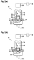
- FIGS. 2a to 2d is schematically and simplifies a not punching riveting 10 according to the invention shown at different phases punch riveting.
- the Punch riveting device 10 has a punch 15, which for example has a round cross section.
- the punch 15 is radially surrounded by a sleeve-shaped hold-down 16 and arranged movable relative to this in the longitudinal direction.
- the punch 15 is coupled to a drive, not shown here, for example a hydraulic or pneumatic drive, which serves to apply a force F required to press a rivet 20 into the two components 11, 12.
- the hold-down 16 is adapted to press against the surface of the die 15 facing member 11 with a hold-down force.
- a separate drive can be provided.
- the hold-down can also be coupled to the drive of the punch 15, for example by means of a spring.
- a counter-acting die 18 is arranged on the stamp 15 and the hold-down 16 opposite side of the two components 11, 12 .
- the die 18 is also in the direction of a longitudinal axis 19, in the direction of which also the punch 15 and the hold-16 are arranged movable, raised and lowered.
- the hold-down 16 and the die 18 serve to clamp or compress the two components 11, 12 between the hold-down 16 and the die 18 during processing by the punch 15.
- the die 18 has, on the side facing the component 12, a planar upper side 21, from which a trough-shaped or recess 22 extends.
- the Matrizenaus brieflyung can be flat, conical or spherical or a dome or. Have thorn in the middle of the recess.
- the rivet 20 here by way of example a half-tubular rivet, preferably consists of a material that is harder than the materials of the two components 11, 12, at least in the region of the rivet shank 24.
- the flat top side facing away from the component 11 is arranged in operative connection with the ram 15. which rests flat on the upper side 26 of the rivet 20.
- the top 26 of the rivet is a contact point 27 between the rivet and the punch.
- the punch 15 is operatively connected to a vibration generator 30 for generating vibrations.
- a vibration generator 30 for generating vibrations.
- the vibrator 30 ultrasonic vibrations with an amplitude (distance between the maximum positive and negative amplitude of a vibration) between 10 .mu.m and 110 .mu.m (corresponding to an amplitude of 5 .mu.m to 55 .mu.m) and a frequency between 15 kHz and 35 kHz or possibly generated higher.
- vibrations 15 are coupled by the vibrator 30 via the punch 15 in the rivet 20.
- the coupling-in direction of the vibrations of the vibration generator 30 can take place, for example, parallel to the longitudinal axis 19, that is to say parallel to the joining direction of the rivet 20 into the components 11, 12.
- the vibration generator 30 is connected to the computing unit 80, and can be controlled by the latter.
- FIG. 2a Phase shown represents a beginning of the Stanzniethabilits in which the rivet shank 24 comes into operative connection with the top of the component 11. In this case, the punch 15 is pressed with the force F against the stamp 15 facing member 11.
- the rivet shank 24 initially cuts or punches into the component 11.
- the two components 11, 12 are plastically deformed, wherein the recess 22 facing the component 12 is pressed in the corresponding areas in the recess 22.
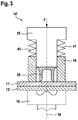
- FIG. 3 is shown schematically and simplified a punch rivet without vibrator. Compared to those in the FIGS. 2a to 2d shown punching riveting the coupling of the blank holder 16 is shown on the punch 15 here.
- the punch 15 has a radial projection on the upper end shown here.
- a spring unit 41 for example.
- the punch riveting device 10 ' has a frame 60, which is preferably in the form of a C-frame or C-bracket, on which the individual components are usually arranged in a punch riveting in order to take the desired position to each other.
- the punch rivet 10 ' for example.
- arm 3 attached. It is understood that even in the in the FIGS. 2a to 2d and 3 Punch riveting shown in the rule, such a frame may be present.
- a drive 50 which may, for example, be a spindle drive or the like, which is suitable for applying a force F for pressing in the rivet 20 into the components 11, 12.
- a holding device 35 for example.
- a vibration system 39 On the holding device 35 is a vibration generator 30, for example.
- the oscillating system 39 is arranged or fastened to the holding device 35 approximately in the center of the booster 31, which has an upper, a wider and a lower, narrower part.
- the punch 15 may, for example, be part of the sonotrode 32, i. that both components can form a structural unit.
- the booster 31 is connected to the holder 35, the booster 31 in the region where it is connected to the holder 35 has no (i.e., vibration nodes) or only a small amplitude of vibration.
- a hold-down 16 ' is shown, which is coupled by means of a spring unit 41, for example. In the form of a cylindrical helical compression spring, to the holding device 35.
- An oscillation of the oscillating system 39 is not transmitted by this type of coupling or at least only slightly to the hold-down 16 '.
- a diagram is shown on the right side of the figure, in which a curve of a vibration amplitude A of an oscillation forming in the vibration system 39 is shown above the position ⁇ .
- the region at which the oscillating system 39 is coupled to the holding device 35 is a point of low oscillation amplitude.
- the oscillation amplitude is generally lower than in the lower region of the plunger 15. In this respect, a possibly still transferable oscillation hardly affects the downholder, since the oscillation amplitude would be very small.
- FIG. 4b a punch rivet 10 'according to the invention is shown in a further preferred embodiment. Opposite the in FIG. 4a shown punch riveting 10 'is the hold-down 16 'is not coupled to the holding device 35, but to the oscillating system 39 in the region of the punch 15 or the sonotrode 32.
- Such a suitable region with little or no oscillation amplitude can be determined, for example, on the basis of the design of the oscillation system 39 or by means of tests.
Landscapes
- Engineering & Computer Science (AREA)
- Mechanical Engineering (AREA)
- Automatic Assembly (AREA)
- Apparatuses For Generation Of Mechanical Vibrations (AREA)
Applications Claiming Priority (1)
| Application Number | Priority Date | Filing Date | Title |
|---|---|---|---|
| DE102015214014.8A DE102015214014A1 (de) | 2015-07-24 | 2015-07-24 | Stanznietvorrichtung und Fertigungsvorrichtung |
Publications (2)
| Publication Number | Publication Date |
|---|---|
| EP3120951A1 true EP3120951A1 (fr) | 2017-01-25 |
| EP3120951B1 EP3120951B1 (fr) | 2020-02-05 |
Family
ID=56112858
Family Applications (1)
| Application Number | Title | Priority Date | Filing Date |
|---|---|---|---|
| EP16172823.3A Active EP3120951B1 (fr) | 2015-07-24 | 2016-06-03 | Dispositif de rivetage et dispositif de fabrication |
Country Status (2)
| Country | Link |
|---|---|
| EP (1) | EP3120951B1 (fr) |
| DE (1) | DE102015214014A1 (fr) |
Cited By (3)
| Publication number | Priority date | Publication date | Assignee | Title |
|---|---|---|---|---|
| CN109909435A (zh) * | 2017-12-12 | 2019-06-21 | 罗伯特·博世有限公司 | 用于冲压铆接装置的安置单元、冲压铆接装置和用于连接构件的方法 |
| EP3505270A1 (fr) * | 2018-01-02 | 2019-07-03 | Robert Bosch GmbH | Unité de frappe pour un dispositif de poinçonnage, dispositif de poinçonnage et procédé de fabrication d'un tel dispositif de poinçonnage |
| GB2570778A (en) * | 2017-12-12 | 2019-08-07 | Bosch Gmbh Robert | Setting unit for a self-piercing rivet device, self-piercing rivet device and method for connecting component parts |
Families Citing this family (2)
| Publication number | Priority date | Publication date | Assignee | Title |
|---|---|---|---|---|
| DE102017205264A1 (de) * | 2017-03-29 | 2018-10-04 | Robert Bosch Gmbh | Stanznietvorrichtung und Fertigungseinrichtung |
| DE102017210458A1 (de) * | 2017-06-22 | 2018-12-27 | Robert Bosch Gmbh | Stanznietvorrichtung mit Schwingungserzeuger |
Citations (5)
| Publication number | Priority date | Publication date | Assignee | Title |
|---|---|---|---|---|
| EP1108480A2 (fr) * | 1999-12-09 | 2001-06-20 | Hahn, Ortwin, Prof. Dr.-Ing. | Dispositif et procede pour realiser un assemblage mecanique |
| EP0890397B1 (fr) * | 1997-07-09 | 2003-03-26 | Hahn, Ortwin, Prof. Dr.-Ing. | Appareil et procédé de joindre mécaniquement des tôles, des profilés ou des connections de tôles multiples |
| DE10341716A1 (de) * | 2003-03-25 | 2004-10-14 | Forschungsgesellschaft Umformtechnik Mbh | Vorrichtung zum radialen Umformen von stab-, rohr- oder drahtförmigen Werkstücken |
| WO2010012973A1 (fr) * | 2008-07-30 | 2010-02-04 | Henrob Limited | Appareil et procédé d'assemblage |
| DE102014203357A1 (de) | 2014-02-25 | 2015-08-27 | Henkel Ag & Co. Kgaa | Darreichungseinheit für eine Masse |
Family Cites Families (2)
| Publication number | Priority date | Publication date | Assignee | Title |
|---|---|---|---|---|
| DE19905527B4 (de) * | 1999-02-10 | 2006-11-23 | Böllhoff GmbH | Vorrichtung zum Fügen von Werkstücken aus duktilem Material |
| DE102014203757B4 (de) * | 2014-02-28 | 2022-03-31 | Robert Bosch Gmbh | Verfahren zum Verbinden wenigstens zweier Bauteile im Stanznietverfahren, Vorrichtung zum Durchführung des Verfahrens, Fertigungseinrichtung und Verwendung des Verfahrens |
-
2015
- 2015-07-24 DE DE102015214014.8A patent/DE102015214014A1/de not_active Withdrawn
-
2016
- 2016-06-03 EP EP16172823.3A patent/EP3120951B1/fr active Active
Patent Citations (6)
| Publication number | Priority date | Publication date | Assignee | Title |
|---|---|---|---|---|
| EP0890397B1 (fr) * | 1997-07-09 | 2003-03-26 | Hahn, Ortwin, Prof. Dr.-Ing. | Appareil et procédé de joindre mécaniquement des tôles, des profilés ou des connections de tôles multiples |
| EP1108480A2 (fr) * | 1999-12-09 | 2001-06-20 | Hahn, Ortwin, Prof. Dr.-Ing. | Dispositif et procede pour realiser un assemblage mecanique |
| DE10341716A1 (de) * | 2003-03-25 | 2004-10-14 | Forschungsgesellschaft Umformtechnik Mbh | Vorrichtung zum radialen Umformen von stab-, rohr- oder drahtförmigen Werkstücken |
| WO2010012973A1 (fr) * | 2008-07-30 | 2010-02-04 | Henrob Limited | Appareil et procédé d'assemblage |
| EP2318161B1 (fr) | 2008-07-30 | 2014-04-30 | Henrob Limited | Appareil et procédé d'assemblage |
| DE102014203357A1 (de) | 2014-02-25 | 2015-08-27 | Henkel Ag & Co. Kgaa | Darreichungseinheit für eine Masse |
Cited By (8)
| Publication number | Priority date | Publication date | Assignee | Title |
|---|---|---|---|---|
| CN109909435A (zh) * | 2017-12-12 | 2019-06-21 | 罗伯特·博世有限公司 | 用于冲压铆接装置的安置单元、冲压铆接装置和用于连接构件的方法 |
| GB2570778A (en) * | 2017-12-12 | 2019-08-07 | Bosch Gmbh Robert | Setting unit for a self-piercing rivet device, self-piercing rivet device and method for connecting component parts |
| GB2570778B (en) * | 2017-12-12 | 2022-12-14 | Bosch Gmbh Robert | Setting unit for a self-piercing rivet device, self-piercing rivet device and method for connecting component parts |
| EP3505270A1 (fr) * | 2018-01-02 | 2019-07-03 | Robert Bosch GmbH | Unité de frappe pour un dispositif de poinçonnage, dispositif de poinçonnage et procédé de fabrication d'un tel dispositif de poinçonnage |
| CN109986017A (zh) * | 2018-01-02 | 2019-07-09 | 罗伯特·博世有限公司 | 振动系统和冲压铆接装置 |
| CN109986018A (zh) * | 2018-01-02 | 2019-07-09 | 罗伯特·博世有限公司 | 用于冲压铆接装置的安置单元、冲压铆接装置以及其制造方法 |
| CN109986017B (zh) * | 2018-01-02 | 2023-09-12 | 罗伯特·博世有限公司 | 振动系统和冲压铆接装置 |
| CN109986018B (zh) * | 2018-01-02 | 2023-09-12 | 罗伯特·博世有限公司 | 用于冲压铆接装置的安置单元、冲压铆接装置以及其制造方法 |
Also Published As
| Publication number | Publication date |
|---|---|
| EP3120951B1 (fr) | 2020-02-05 |
| DE102015214014A1 (de) | 2017-01-26 |
Similar Documents
| Publication | Publication Date | Title |
|---|---|---|
| DE102014203757A1 (de) | Verfahren zum Verbinden wenigstens zweier Bauteile im Stanznietverfahren, Vorrichtung zum Durchführung des Verfahrens, Fertigungseinrichtung und Verwendung des Verfahrens | |
| EP3505270B1 (fr) | Unité de frappe pour un dispositif de poinçonnage, dispositif de poinçonnage et procédé de fabrication d'un tel dispositif de poinçonnage | |
| EP3120951B1 (fr) | Dispositif de rivetage et dispositif de fabrication | |
| EP3124803B1 (fr) | Dispositif de rivetage | |
| EP3120950B1 (fr) | Élément de transmission pour un dispositif de rivetage, dispositif de rivetage, dispositif de fabrication et procé de détermination d'un comportement aux vibrations | |
| EP3133302A1 (fr) | Poinçonnage par rivets | |
| DE102015007295B3 (de) | Setzvorrichtung | |
| EP1115518A1 (fr) | Procede et dispositif pour assembler des elements sous forme de plaques qui se chevauchent | |
| EP3332886B1 (fr) | Procédé et dispositif de surveillance du rivetage avec rivet auto-poinçonneur | |
| EP3281721B1 (fr) | Procédé de fixation d'au moins deux composants au moyen d'un dispositif de rivetage auto-poinconnant et dispositif de fabrication | |
| EP3552729A1 (fr) | Dispositif d'installation de rivets auto-poinçonneurs | |
| DE19929778B4 (de) | Verfahren und Vorrichtung zum dynamischen Verbinden von plattenförmigen Bauteilen | |
| EP3117925A1 (fr) | Dispositif de rivetage et dispositif de fabrication | |
| DE102018222841A1 (de) | Setzeinheit für eine Stanznietvorrichtung, Stanznietvorrichtung und Verfahren zum Verbinden von Bauteilen | |
| DE102017213233A1 (de) | Stanznietvorrichtung und Verfahren zum Verbinden von Bauteilen | |
| EP3381581B1 (fr) | Dispositif de poinçonnage et procédé de fonctionnement d'un dispositif de poinçonnage | |
| EP3546084B1 (fr) | Procédé de liaison d'au moins deux composants au moyen d'un dispositif de rivetage et dispositif de rivetage | |
| DE102018205621A1 (de) | Stanznietvorrichtung mit Zuführeinheit für Niete | |
| DE102016208067A1 (de) | Stanznietvorrichtung und Fertigungsvorrichtung | |
| DE102016226246A1 (de) | Verfahren zum Betreiben einer Fügevorrichtung, Fügevorrichtung und Anordnung mit Fügevorrichtung | |
| EP3388165B1 (fr) | Dispositif de pose de rivets auto-poinconnants et dispositif de fabrication | |
| DE102017215108A1 (de) | Stanznietvorrichtung und Verfahren zum Verbinden wenigstens zweier Bauteile | |
| EP3552731A1 (fr) | Unité de pose pour un dispositif rivet auto-poinçonneur et dispositif rivet auto-poinçonneur | |
| DE102017213242A1 (de) | Fügevorrichtung | |
| DE102018205101A1 (de) | Verfahren zum Verbinden wenigstens zweier Bauteile mittels einer Stanznietvorrichtung und Stanznietvorrichtung |
Legal Events
| Date | Code | Title | Description |
|---|---|---|---|
| PUAI | Public reference made under article 153(3) epc to a published international application that has entered the european phase |
Free format text: ORIGINAL CODE: 0009012 |
|
| STAA | Information on the status of an ep patent application or granted ep patent |
Free format text: STATUS: THE APPLICATION HAS BEEN PUBLISHED |
|
| AK | Designated contracting states |
Kind code of ref document: A1 Designated state(s): AL AT BE BG CH CY CZ DE DK EE ES FI FR GB GR HR HU IE IS IT LI LT LU LV MC MK MT NL NO PL PT RO RS SE SI SK SM TR |
|
| AX | Request for extension of the european patent |
Extension state: BA ME |
|
| STAA | Information on the status of an ep patent application or granted ep patent |
Free format text: STATUS: REQUEST FOR EXAMINATION WAS MADE |
|
| 17P | Request for examination filed |
Effective date: 20170725 |
|
| RBV | Designated contracting states (corrected) |
Designated state(s): AL AT BE BG CH CY CZ DE DK EE ES FI FR GB GR HR HU IE IS IT LI LT LU LV MC MK MT NL NO PL PT RO RS SE SI SK SM TR |
|
| STAA | Information on the status of an ep patent application or granted ep patent |
Free format text: STATUS: EXAMINATION IS IN PROGRESS |
|
| 17Q | First examination report despatched |
Effective date: 20180705 |
|
| GRAP | Despatch of communication of intention to grant a patent |
Free format text: ORIGINAL CODE: EPIDOSNIGR1 |
|
| STAA | Information on the status of an ep patent application or granted ep patent |
Free format text: STATUS: GRANT OF PATENT IS INTENDED |
|
| INTG | Intention to grant announced |
Effective date: 20191114 |
|
| GRAS | Grant fee paid |
Free format text: ORIGINAL CODE: EPIDOSNIGR3 |
|
| GRAA | (expected) grant |
Free format text: ORIGINAL CODE: 0009210 |
|
| STAA | Information on the status of an ep patent application or granted ep patent |
Free format text: STATUS: THE PATENT HAS BEEN GRANTED |
|
| AK | Designated contracting states |
Kind code of ref document: B1 Designated state(s): AL AT BE BG CH CY CZ DE DK EE ES FI FR GB GR HR HU IE IS IT LI LT LU LV MC MK MT NL NO PL PT RO RS SE SI SK SM TR |
|
| REG | Reference to a national code |
Ref country code: GB Ref legal event code: FG4D Free format text: NOT ENGLISH |
|
| REG | Reference to a national code |
Ref country code: AT Ref legal event code: REF Ref document number: 1229546 Country of ref document: AT Kind code of ref document: T Effective date: 20200215 |
|
| REG | Reference to a national code |
Ref country code: DE Ref legal event code: R096 Ref document number: 502016008608 Country of ref document: DE |
|
| REG | Reference to a national code |
Ref country code: IE Ref legal event code: FG4D Free format text: LANGUAGE OF EP DOCUMENT: GERMAN |
|
| REG | Reference to a national code |
Ref country code: CH Ref legal event code: EP |
|
| RAP2 | Party data changed (patent owner data changed or rights of a patent transferred) |
Owner name: ROBERT BOSCH GMBH |
|
| REG | Reference to a national code |
Ref country code: NL Ref legal event code: MP Effective date: 20200205 |
|
| PG25 | Lapsed in a contracting state [announced via postgrant information from national office to epo] |
Ref country code: PT Free format text: LAPSE BECAUSE OF FAILURE TO SUBMIT A TRANSLATION OF THE DESCRIPTION OR TO PAY THE FEE WITHIN THE PRESCRIBED TIME-LIMIT Effective date: 20200628 Ref country code: NO Free format text: LAPSE BECAUSE OF FAILURE TO SUBMIT A TRANSLATION OF THE DESCRIPTION OR TO PAY THE FEE WITHIN THE PRESCRIBED TIME-LIMIT Effective date: 20200505 Ref country code: FI Free format text: LAPSE BECAUSE OF FAILURE TO SUBMIT A TRANSLATION OF THE DESCRIPTION OR TO PAY THE FEE WITHIN THE PRESCRIBED TIME-LIMIT Effective date: 20200205 Ref country code: RS Free format text: LAPSE BECAUSE OF FAILURE TO SUBMIT A TRANSLATION OF THE DESCRIPTION OR TO PAY THE FEE WITHIN THE PRESCRIBED TIME-LIMIT Effective date: 20200205 |
|
| REG | Reference to a national code |
Ref country code: LT Ref legal event code: MG4D |
|
| PG25 | Lapsed in a contracting state [announced via postgrant information from national office to epo] |
Ref country code: BG Free format text: LAPSE BECAUSE OF FAILURE TO SUBMIT A TRANSLATION OF THE DESCRIPTION OR TO PAY THE FEE WITHIN THE PRESCRIBED TIME-LIMIT Effective date: 20200505 Ref country code: GR Free format text: LAPSE BECAUSE OF FAILURE TO SUBMIT A TRANSLATION OF THE DESCRIPTION OR TO PAY THE FEE WITHIN THE PRESCRIBED TIME-LIMIT Effective date: 20200506 Ref country code: IS Free format text: LAPSE BECAUSE OF FAILURE TO SUBMIT A TRANSLATION OF THE DESCRIPTION OR TO PAY THE FEE WITHIN THE PRESCRIBED TIME-LIMIT Effective date: 20200605 Ref country code: SE Free format text: LAPSE BECAUSE OF FAILURE TO SUBMIT A TRANSLATION OF THE DESCRIPTION OR TO PAY THE FEE WITHIN THE PRESCRIBED TIME-LIMIT Effective date: 20200205 Ref country code: LV Free format text: LAPSE BECAUSE OF FAILURE TO SUBMIT A TRANSLATION OF THE DESCRIPTION OR TO PAY THE FEE WITHIN THE PRESCRIBED TIME-LIMIT Effective date: 20200205 Ref country code: HR Free format text: LAPSE BECAUSE OF FAILURE TO SUBMIT A TRANSLATION OF THE DESCRIPTION OR TO PAY THE FEE WITHIN THE PRESCRIBED TIME-LIMIT Effective date: 20200205 |
|
| PG25 | Lapsed in a contracting state [announced via postgrant information from national office to epo] |
Ref country code: NL Free format text: LAPSE BECAUSE OF FAILURE TO SUBMIT A TRANSLATION OF THE DESCRIPTION OR TO PAY THE FEE WITHIN THE PRESCRIBED TIME-LIMIT Effective date: 20200205 |
|
| PG25 | Lapsed in a contracting state [announced via postgrant information from national office to epo] |
Ref country code: ES Free format text: LAPSE BECAUSE OF FAILURE TO SUBMIT A TRANSLATION OF THE DESCRIPTION OR TO PAY THE FEE WITHIN THE PRESCRIBED TIME-LIMIT Effective date: 20200205 Ref country code: DK Free format text: LAPSE BECAUSE OF FAILURE TO SUBMIT A TRANSLATION OF THE DESCRIPTION OR TO PAY THE FEE WITHIN THE PRESCRIBED TIME-LIMIT Effective date: 20200205 Ref country code: SK Free format text: LAPSE BECAUSE OF FAILURE TO SUBMIT A TRANSLATION OF THE DESCRIPTION OR TO PAY THE FEE WITHIN THE PRESCRIBED TIME-LIMIT Effective date: 20200205 Ref country code: SM Free format text: LAPSE BECAUSE OF FAILURE TO SUBMIT A TRANSLATION OF THE DESCRIPTION OR TO PAY THE FEE WITHIN THE PRESCRIBED TIME-LIMIT Effective date: 20200205 Ref country code: CZ Free format text: LAPSE BECAUSE OF FAILURE TO SUBMIT A TRANSLATION OF THE DESCRIPTION OR TO PAY THE FEE WITHIN THE PRESCRIBED TIME-LIMIT Effective date: 20200205 Ref country code: LT Free format text: LAPSE BECAUSE OF FAILURE TO SUBMIT A TRANSLATION OF THE DESCRIPTION OR TO PAY THE FEE WITHIN THE PRESCRIBED TIME-LIMIT Effective date: 20200205 Ref country code: EE Free format text: LAPSE BECAUSE OF FAILURE TO SUBMIT A TRANSLATION OF THE DESCRIPTION OR TO PAY THE FEE WITHIN THE PRESCRIBED TIME-LIMIT Effective date: 20200205 Ref country code: RO Free format text: LAPSE BECAUSE OF FAILURE TO SUBMIT A TRANSLATION OF THE DESCRIPTION OR TO PAY THE FEE WITHIN THE PRESCRIBED TIME-LIMIT Effective date: 20200205 |
|
| REG | Reference to a national code |
Ref country code: DE Ref legal event code: R097 Ref document number: 502016008608 Country of ref document: DE |
|
| PLBE | No opposition filed within time limit |
Free format text: ORIGINAL CODE: 0009261 |
|
| STAA | Information on the status of an ep patent application or granted ep patent |
Free format text: STATUS: NO OPPOSITION FILED WITHIN TIME LIMIT |
|
| 26N | No opposition filed |
Effective date: 20201106 |
|
| PG25 | Lapsed in a contracting state [announced via postgrant information from national office to epo] |
Ref country code: MC Free format text: LAPSE BECAUSE OF FAILURE TO SUBMIT A TRANSLATION OF THE DESCRIPTION OR TO PAY THE FEE WITHIN THE PRESCRIBED TIME-LIMIT Effective date: 20200205 |
|
| REG | Reference to a national code |
Ref country code: CH Ref legal event code: PL |
|
| PG25 | Lapsed in a contracting state [announced via postgrant information from national office to epo] |
Ref country code: PL Free format text: LAPSE BECAUSE OF FAILURE TO SUBMIT A TRANSLATION OF THE DESCRIPTION OR TO PAY THE FEE WITHIN THE PRESCRIBED TIME-LIMIT Effective date: 20200205 Ref country code: SI Free format text: LAPSE BECAUSE OF FAILURE TO SUBMIT A TRANSLATION OF THE DESCRIPTION OR TO PAY THE FEE WITHIN THE PRESCRIBED TIME-LIMIT Effective date: 20200205 |
|
| PG25 | Lapsed in a contracting state [announced via postgrant information from national office to epo] |
Ref country code: LU Free format text: LAPSE BECAUSE OF NON-PAYMENT OF DUE FEES Effective date: 20200603 |
|
| REG | Reference to a national code |
Ref country code: BE Ref legal event code: MM Effective date: 20200630 |
|
| PG25 | Lapsed in a contracting state [announced via postgrant information from national office to epo] |
Ref country code: IE Free format text: LAPSE BECAUSE OF NON-PAYMENT OF DUE FEES Effective date: 20200603 Ref country code: CH Free format text: LAPSE BECAUSE OF NON-PAYMENT OF DUE FEES Effective date: 20200630 Ref country code: LI Free format text: LAPSE BECAUSE OF NON-PAYMENT OF DUE FEES Effective date: 20200630 |
|
| PG25 | Lapsed in a contracting state [announced via postgrant information from national office to epo] |
Ref country code: BE Free format text: LAPSE BECAUSE OF NON-PAYMENT OF DUE FEES Effective date: 20200630 |
|
| PG25 | Lapsed in a contracting state [announced via postgrant information from national office to epo] |
Ref country code: TR Free format text: LAPSE BECAUSE OF FAILURE TO SUBMIT A TRANSLATION OF THE DESCRIPTION OR TO PAY THE FEE WITHIN THE PRESCRIBED TIME-LIMIT Effective date: 20200205 Ref country code: MT Free format text: LAPSE BECAUSE OF FAILURE TO SUBMIT A TRANSLATION OF THE DESCRIPTION OR TO PAY THE FEE WITHIN THE PRESCRIBED TIME-LIMIT Effective date: 20200205 Ref country code: CY Free format text: LAPSE BECAUSE OF FAILURE TO SUBMIT A TRANSLATION OF THE DESCRIPTION OR TO PAY THE FEE WITHIN THE PRESCRIBED TIME-LIMIT Effective date: 20200205 |
|
| PG25 | Lapsed in a contracting state [announced via postgrant information from national office to epo] |
Ref country code: MK Free format text: LAPSE BECAUSE OF FAILURE TO SUBMIT A TRANSLATION OF THE DESCRIPTION OR TO PAY THE FEE WITHIN THE PRESCRIBED TIME-LIMIT Effective date: 20200205 Ref country code: AL Free format text: LAPSE BECAUSE OF FAILURE TO SUBMIT A TRANSLATION OF THE DESCRIPTION OR TO PAY THE FEE WITHIN THE PRESCRIBED TIME-LIMIT Effective date: 20200205 |
|
| REG | Reference to a national code |
Ref country code: AT Ref legal event code: MM01 Ref document number: 1229546 Country of ref document: AT Kind code of ref document: T Effective date: 20210603 |
|
| PG25 | Lapsed in a contracting state [announced via postgrant information from national office to epo] |
Ref country code: AT Free format text: LAPSE BECAUSE OF NON-PAYMENT OF DUE FEES Effective date: 20210603 |
|
| PGFP | Annual fee paid to national office [announced via postgrant information from national office to epo] |
Ref country code: GB Payment date: 20250620 Year of fee payment: 10 |
|
| PGFP | Annual fee paid to national office [announced via postgrant information from national office to epo] |
Ref country code: FR Payment date: 20250618 Year of fee payment: 10 |
|
| PGFP | Annual fee paid to national office [announced via postgrant information from national office to epo] |
Ref country code: DE Payment date: 20250814 Year of fee payment: 10 |
|
| PGFP | Annual fee paid to national office [announced via postgrant information from national office to epo] |
Ref country code: IT Payment date: 20250630 Year of fee payment: 10 |