EP3121020A2 - Ausstossvorrichtung - Google Patents
Ausstossvorrichtung Download PDFInfo
- Publication number
- EP3121020A2 EP3121020A2 EP16178890.6A EP16178890A EP3121020A2 EP 3121020 A2 EP3121020 A2 EP 3121020A2 EP 16178890 A EP16178890 A EP 16178890A EP 3121020 A2 EP3121020 A2 EP 3121020A2
- Authority
- EP
- European Patent Office
- Prior art keywords
- position adjusting
- discharger
- ejection device
- mark
- nail
- Prior art date
- Legal status (The legal status is an assumption and is not a legal conclusion. Google has not performed a legal analysis and makes no representation as to the accuracy of the status listed.)
- Withdrawn
Links
- 238000003384 imaging method Methods 0.000 claims abstract description 26
- 238000007599 discharging Methods 0.000 claims abstract description 23
- 238000006073 displacement reaction Methods 0.000 claims description 64
- 230000007246 mechanism Effects 0.000 claims description 55
- 239000002537 cosmetic Substances 0.000 claims description 5
- 239000003814 drug Substances 0.000 claims description 5
- 210000000282 nail Anatomy 0.000 description 120
- 238000010586 diagram Methods 0.000 description 13
- 238000000034 method Methods 0.000 description 11
- 239000003973 paint Substances 0.000 description 10
- 238000010422 painting Methods 0.000 description 4
- 210000004905 finger nail Anatomy 0.000 description 3
- 230000033001 locomotion Effects 0.000 description 3
- 230000008901 benefit Effects 0.000 description 1
- 238000004040 coloring Methods 0.000 description 1
- 230000001419 dependent effect Effects 0.000 description 1
- 230000000694 effects Effects 0.000 description 1
- 239000012530 fluid Substances 0.000 description 1
- 239000007788 liquid Substances 0.000 description 1
- NJPPVKZQTLUDBO-UHFFFAOYSA-N novaluron Chemical compound C1=C(Cl)C(OC(F)(F)C(OC(F)(F)F)F)=CC=C1NC(=O)NC(=O)C1=C(F)C=CC=C1F NJPPVKZQTLUDBO-UHFFFAOYSA-N 0.000 description 1
- 230000008569 process Effects 0.000 description 1
- 230000009467 reduction Effects 0.000 description 1
- 238000005507 spraying Methods 0.000 description 1
Images


Classifications
-
- B—PERFORMING OPERATIONS; TRANSPORTING
- B41—PRINTING; LINING MACHINES; TYPEWRITERS; STAMPS
- B41J—TYPEWRITERS; SELECTIVE PRINTING MECHANISMS, i.e. MECHANISMS PRINTING OTHERWISE THAN FROM A FORME; CORRECTION OF TYPOGRAPHICAL ERRORS
- B41J2/00—Typewriters or selective printing mechanisms characterised by the printing or marking process for which they are designed
- B41J2/005—Typewriters or selective printing mechanisms characterised by the printing or marking process for which they are designed characterised by bringing liquid or particles selectively into contact with a printing material
- B41J2/01—Ink jet
- B41J2/015—Ink jet characterised by the jet generation process
- B41J2/04—Ink jet characterised by the jet generation process generating single droplets or particles on demand
- B41J2/045—Ink jet characterised by the jet generation process generating single droplets or particles on demand by pressure, e.g. electromechanical transducers
- B41J2/04501—Control methods or devices therefor, e.g. driver circuits, control circuits
- B41J2/04536—Control methods or devices therefor, e.g. driver circuits, control circuits using history data
-
- B—PERFORMING OPERATIONS; TRANSPORTING
- B41—PRINTING; LINING MACHINES; TYPEWRITERS; STAMPS
- B41J—TYPEWRITERS; SELECTIVE PRINTING MECHANISMS, i.e. MECHANISMS PRINTING OTHERWISE THAN FROM A FORME; CORRECTION OF TYPOGRAPHICAL ERRORS
- B41J3/00—Typewriters or selective printing or marking mechanisms characterised by the purpose for which they are constructed
- B41J3/407—Typewriters or selective printing or marking mechanisms characterised by the purpose for which they are constructed for marking on special material
-
- A—HUMAN NECESSITIES
- A45—HAND OR TRAVELLING ARTICLES
- A45D—HAIRDRESSING OR SHAVING EQUIPMENT; EQUIPMENT FOR COSMETICS OR COSMETIC TREATMENTS, e.g. FOR MANICURING OR PEDICURING
- A45D29/00—Manicuring or pedicuring implements
-
- B—PERFORMING OPERATIONS; TRANSPORTING
- B41—PRINTING; LINING MACHINES; TYPEWRITERS; STAMPS
- B41J—TYPEWRITERS; SELECTIVE PRINTING MECHANISMS, i.e. MECHANISMS PRINTING OTHERWISE THAN FROM A FORME; CORRECTION OF TYPOGRAPHICAL ERRORS
- B41J11/00—Devices or arrangements of selective printing mechanisms, e.g. ink-jet printers or thermal printers, for supporting or handling copy material in sheet or web form
- B41J11/0015—Devices or arrangements of selective printing mechanisms, e.g. ink-jet printers or thermal printers, for supporting or handling copy material in sheet or web form for treating before, during or after printing or for uniform coating or laminating the copy material before or after printing
-
- B—PERFORMING OPERATIONS; TRANSPORTING
- B41—PRINTING; LINING MACHINES; TYPEWRITERS; STAMPS
- B41J—TYPEWRITERS; SELECTIVE PRINTING MECHANISMS, i.e. MECHANISMS PRINTING OTHERWISE THAN FROM A FORME; CORRECTION OF TYPOGRAPHICAL ERRORS
- B41J11/00—Devices or arrangements of selective printing mechanisms, e.g. ink-jet printers or thermal printers, for supporting or handling copy material in sheet or web form
- B41J11/008—Controlling printhead for accurately positioning print image on printing material, e.g. with the intention to control the width of margins
-
- B—PERFORMING OPERATIONS; TRANSPORTING
- B41—PRINTING; LINING MACHINES; TYPEWRITERS; STAMPS
- B41J—TYPEWRITERS; SELECTIVE PRINTING MECHANISMS, i.e. MECHANISMS PRINTING OTHERWISE THAN FROM A FORME; CORRECTION OF TYPOGRAPHICAL ERRORS
- B41J11/00—Devices or arrangements of selective printing mechanisms, e.g. ink-jet printers or thermal printers, for supporting or handling copy material in sheet or web form
- B41J11/36—Blanking or long feeds; Feeding to a particular line, e.g. by rotation of platen or feed roller
- B41J11/42—Controlling printing material conveyance for accurate alignment of the printing material with the printhead; Print registering
- B41J11/46—Controlling printing material conveyance for accurate alignment of the printing material with the printhead; Print registering by marks or formations on the paper being fed
-
- B—PERFORMING OPERATIONS; TRANSPORTING
- B41—PRINTING; LINING MACHINES; TYPEWRITERS; STAMPS
- B41J—TYPEWRITERS; SELECTIVE PRINTING MECHANISMS, i.e. MECHANISMS PRINTING OTHERWISE THAN FROM A FORME; CORRECTION OF TYPOGRAPHICAL ERRORS
- B41J2/00—Typewriters or selective printing mechanisms characterised by the printing or marking process for which they are designed
- B41J2/005—Typewriters or selective printing mechanisms characterised by the printing or marking process for which they are designed characterised by bringing liquid or particles selectively into contact with a printing material
- B41J2/01—Ink jet
- B41J2/015—Ink jet characterised by the jet generation process
- B41J2/04—Ink jet characterised by the jet generation process generating single droplets or particles on demand
- B41J2/045—Ink jet characterised by the jet generation process generating single droplets or particles on demand by pressure, e.g. electromechanical transducers
- B41J2/04501—Control methods or devices therefor, e.g. driver circuits, control circuits
- B41J2/04586—Control methods or devices therefor, e.g. driver circuits, control circuits controlling heads of a type not covered by groups B41J2/04575 - B41J2/04585, or of an undefined type
-
- B—PERFORMING OPERATIONS; TRANSPORTING
- B41—PRINTING; LINING MACHINES; TYPEWRITERS; STAMPS
- B41J—TYPEWRITERS; SELECTIVE PRINTING MECHANISMS, i.e. MECHANISMS PRINTING OTHERWISE THAN FROM A FORME; CORRECTION OF TYPOGRAPHICAL ERRORS
- B41J25/00—Actions or mechanisms not otherwise provided for
- B41J25/001—Mechanisms for bodily moving print heads or carriages parallel to the paper surface
-
- B—PERFORMING OPERATIONS; TRANSPORTING
- B41—PRINTING; LINING MACHINES; TYPEWRITERS; STAMPS
- B41J—TYPEWRITERS; SELECTIVE PRINTING MECHANISMS, i.e. MECHANISMS PRINTING OTHERWISE THAN FROM A FORME; CORRECTION OF TYPOGRAPHICAL ERRORS
- B41J3/00—Typewriters or selective printing or marking mechanisms characterised by the purpose for which they are constructed
- B41J3/407—Typewriters or selective printing or marking mechanisms characterised by the purpose for which they are constructed for marking on special material
- B41J3/4073—Printing on three-dimensional objects not being in sheet or web form, e.g. spherical or cubic objects
-
- A—HUMAN NECESSITIES
- A45—HAND OR TRAVELLING ARTICLES
- A45D—HAIRDRESSING OR SHAVING EQUIPMENT; EQUIPMENT FOR COSMETICS OR COSMETIC TREATMENTS, e.g. FOR MANICURING OR PEDICURING
- A45D29/00—Manicuring or pedicuring implements
- A45D2029/005—Printing or stamping devices for applying images or ornaments to nails
Definitions
- the present invention relates generally to an ejection device.
- the present invention also relates to a method for printing on an object.
- Nail printers print on a fingernail a color or a pattern selected by a user to perform a nail design on a fingernail.
- patent document 1 discloses a configuration of the nail printer that can perform a test painting using test paint paper.
- Patent Document 1 Japanese Unexamined Patent Application Publication No. 2012-232039
- test painting is performed to improve the quality of nail design.
- this configuration requires a test painting area in the nail printer, which makes it difficult to decrease the size of the printer.
- the test painting also increases running costs because it requires paper.
- the test print area and an actual print area on the nail may differ, it is difficult to adjust the print position with high accuracy.
- One or more embodiments of the invention provide an ejection device that can eject a droplet such as ink with high accuracy without needing a test paint area or a test paint paper.
- an ejection device comprises: a moveable discharger configured to discharge a droplet on an object; an imaging device configured to capture an image of the object; and a controller configured to control the discharger based on the captured image of the object.
- an ejection device comprises: a discharger configured to discharge a droplet on an object; a motor configured to move the discharger; an imaging device configured to capture an image of the object; and a controller configured to control the discharger and the motor based on the captured image of the object.
- the controller is configured to: control the discharger and the motor; and receive the captured image from the imaging device, wherein the discharger is configured to output a position adjusting mark on the object before discharging the droplet on the object, and the controller is configured to adjust a discharge position of the droplet based on the captured image of the object with the position adjusting mark.
- an ejection device can eject a droplet such as ink with high accuracy, without needing a test paint area or a test paint paper.
- the discharger is configured to apply a base coat on the object after the discharge position is adjusted.
- a reference mark showing a reference position is provided in an imaging range for the captured image of the object in a housing, the controller is configured to detect a displacement amount of the distance between the position adjusting mark and the reference mark shown on the captured image of the object, and the controller is configured to adjust the discharge position based on the displacement amount.
- the controller is configured to receive the captured image of the object before the position adjusting mark is output, and the discharger is configured to output the position adjusting mark at a predetermined position in a range of the object recognized from the captured image.
- the discharger is configured to discharge the droplet while moving in a first direction
- the discharger is configured to repeat the discharging of the droplet until the discharger reaches an end of lines in a second direction perpendicular to the first direction
- the controller is configured to adjust the discharge position in at least one of the first and the second direction.
- the discharger is configured to discharge the droplet while moving in a first direction and an opposite direction against the first direction, the discharger is configured to repeat the discharging of the droplet until the discharger reaches an end of lines in a second direction perpendicular to the first direction, the discharger is configured to output the position adjusting mark when moving in the first direction and also when moving in the opposite direction, and the controller is configured to adjust the discharge position individually for the first and the opposite direction.
- the controller when the displacement amount exceeds a threshold value, the controller is configured to adjust the discharge position to decrease the amount of displacement, and the discharger is further configured to output the position adjusting mark.
- the predetermined position is a center of the range of the object.
- the position adjusting mark is output at a lower color tone than the droplet discharged on the object.
- the position adjusting mark is output at a width of approximately 20% of a range of the object recognized from the captured image.
- the imaging device is configured to capture multiple images of the object before the position adjusting mark is output, and the controller is configured to recognize the range of the object based on the captured images of the object.
- the imaging device is configured to capture multiple images of the object with the position adjusting mark after the position adjusting mark is output, and the controller is configured to adjust the discharge position based on the captured images of the object with the position adjusting mark.
- the reference mark is provided on each of two axes which extend through a center of the imaging range and are perpendicular to each other, and the controller is configured to detect the displacement amount in each of the axes and to adjust the discharge position based on the detected displacement amount in each of the axes.
- the controller is configured to adjust the discharge position to decrease the displacement amount when the displacement amount of one of the two axes exceeds a first threshold value or when the displacement amount of the other axis exceeds a second threshold value.
- the second threshold value is higher than the first threshold value.
- the second threshold value is set for the displacement amount in one of the two axes perpendicular to a direction in which the discharger moves while discharging the droplet.
- the droplet is a cosmetic droplet.
- the droplet is a medicine droplet.
- the ejection device further comprises a fixing mechanism configured to fix the object.
- a method for printing on an object comprises: discharging a droplet, such as for example a cosmetic or a medicine droplet, on an object; capturing an image of the object; and controlling the discharging based on the captured image of the object.
- a droplet such as for example a cosmetic or a medicine droplet
- the method comprises discharging a droplet on an object along a first direction and a second direction perpendicular to the first direction; capturing an image of the object; and controlling the discharging based on the captured image of the object.
- the method comprises adjusting a discharge position in at least one of the first and second direction.
- the method comprises controlling the discharging; and receiving the captured image, wherein the method further comprises outputting a position adjusting mark on the object before discharging the droplet on the object, and adjusting a discharge position of the droplet based on the captured image of the object with the position adjusting mark.
- Further embodiments of the method comprise steps corresponding to the features of one or more embodiments of the ejection device.
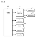
- FIG. 1 is a diagram illustrating the schematic configuration of components of a printer according to one or more embodiments of the invention.
- FIG. 1 shows a finger fixing mechanism 50 for fixing a finger FN to a prescribed position, and an ink mechanism 10 that performs printing on a nail NL of the finger FN placed in the prescribed position.
- FIG. 1 shows a finger fixing mechanism 50 for fixing a finger FN to a prescribed position, and an ink mechanism 10 that performs printing on a nail NL of the finger FN placed in the prescribed position.
- FIG. 1 also shows an X-axis motor 1 that moves the ink mechanism 10 in the X direction, or in other words, in a direction that is orthogonal to a direction in which the finger FN extends in a planar view, by driving an X-axis motor belt 3 connected to the ink mechanism 10. Also shown is a Y-axis motor 2 that moves the ink mechanism 10 in a Y-direction, or in other words, the direction in which the finger FN extends, by rotating a Y-axis motor shaft 4 connected to the ink mechanism 10. A direction X1 and an opposite direction X2 are shown in the X direction, and a direction Y1 and an opposite direction Y2 are shown in the Y direction.
- the ink mechanism 10 may have a print head 11 (example of discharge portion or discharger) for discharging ink (droplet) on the nail NL.
- the print head 11 includes a first print head 11a for colored ink, and a second print head 11b for primer ink.
- the first print head 11a for colored ink performs printing for carrying out a color design on the nail NL.
- the second print head 11b for primer ink performs printing for improving, for example, coloring of colored ink and the like.
- the printing of a nail design is performed by the first print head 11a, and the application of a base coat and a top coat is performed by the second print head 11b.
- the number and type of print heads are not limited to that described here.
- the print head 11 is an ink jet type print head that performs printing by making ink into fine droplets and spraying directly on a nail.
- the printing type of the print head is not limited to an ink jet type.
- the ink mechanism 10 may have a camera 15 as an imaging portion (imaging device).
- the camera 15 images the nail NL of the finger FN placed on the prescribed position.
- the captured image is used to define the range of the nail NL, or in other words, the range wherein printing is performed.
- FIG. 2 is a block diagram illustrating the functional configuration of a printer according to one or more embodiments of the invention.
- a control unit 20 controls a printing operation of a printer.
- the control unit 20 performs input/output of a signal between a motor drive control unit 5, and controls the operation of the X-axis motor 1 and the Y-axis motor 2.
- a motor portion that moves the ink mechanism 10 by driving a motor is configured by the X-axis motor 1, Y-axis motor 2, X-axis motor belt 3, Y-axis motor shaft 4, and motor drive control unit 5.
- the control unit 20 controls the moving operation of the ink mechanism 10 by the motor portion.
- control unit 20 controls operation of the ink mechanism 10, for example, an operation for discharging ink from the print head 11. Furthermore, the captured image from the camera 15 is made to be input, and setting of, for example, the range of the nail NL, namely, the printing range is performed from this captured image. In addition to this, signal input/output between a switch type 6 and a sensor type 7 provided on the printer is also performed, although a detailed description is omitted.
- the ink mechanism 10 performs the operation for discharging ink while moving in an X direction (corresponding to a first direction) by the control of the control unit 20 when performing printing.
- the operation for discharging ink while moving in the X direction is performed repeatedly while moving in a Y direction (corresponding to a second direction perpendicular to the first direction). In other words, the operation is performed repeatedly until the ink mechanism 10 reaches an end of lines in the Y direction.
- control unit 20 performs the print position (discharge position) adjusting operation before performing printing on the nail NL.
- a position adjusting mark is printed (output) on the nail NL.
- this is made for adjusting the print position in the X direction.
- FIG. 3 is a flow chart illustrating the flow of a print position adjusting operation according to one or more embodiments of the present invention. Following the flow of FIG. 3 , the print position adjusting operation according to one or more embodiments of the present invention will be described with reference to FIG. 4 .
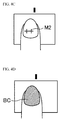
- a reference mark 21 showing a reference position is provided on a housing in the vicinity of the print area where the nail NL of the finger FN is placed, as illustrated in FIG. 4A .
- the reference mark 21 may be, for example, a carved marking provided on the housing, or may be printed on the housing.
- the reference mark 21 is provided within an imaging range of the camera 15.
- the control unit 20 first acquires an image of the nail NL by capturing it with the camera 15 (S11). Then, as illustrated in FIG. 5A , the range of the nail NL is recognized from the acquired nail image by image recognition (S12). In FIG. 5A , the hatched range of the nail NL becomes the printing range.
- the control unit 20 may adjust an exposure or the like, and acquire a plurality of images in order to accurately recognize the printing range.
- the control unit 20 prints a position adjusting mark M1 on the nail NL by the ink mechanism 10 (S13).
- the position adjusting mark M1 may, for example, be printed by the primer print head 11b.
- the position adjusting mark M1 may, for example, be printed in a color tone lower than the color tone of the ink used for printing the nail design.
- the control unit 20 prints the position adjusting mark M1 on, for example, a center portion of the prescribed position in the range of the nail NL recognized in the nail image.
- the control unit 20 can, for example, print the position adjusting mark M1 with a width (in the X-axis direction) of approximately 20% of the range of the nail NL, as illustrated in FIG. 4B .
- the control unit 20 can print the position adjusting mark M1 of any size.
- the position adjusting mark M1 is not limited to always being printed to the prescribed position in the nail range due to backlash and the like of the motor. In other words, there is a possibility of displacement occurring between the prescribed position where the control unit 20 intends to print, and the position where the printing actually takes place. Because of this, adjusting the print position is necessary.
- the control unit 20 acquires an image of the nail NL with the position adjusting mark M1 printed thereon by capturing it with the camera 15(S14). Then, a displacement amount of the position adjusting mark M1 is recognized from the acquired nail image (S15). At this time, the displacement amount is recognized with the reference mark 21 as a reference.
- a displacement amount dx1 of the position of the reference mark 21 and a prescribed position in the nail range for example, the center portion position shown with a dash-dot line in FIG. 5B
- a displacement amount dx2 of the position of the reference mark 21 and the print position of the position adjusting mark M1 is requested.
- the displacement amount of the position adjusting mark M1 is requested by comparing these two displacement amounts dx1 and dx2.
- the displacement amount at this time is given a positive or negative value based on the direction of the displacement with the position of the reference mark 21 as zero.
- the direction X1 side may be positive, and the direction X2 side may be negative.
- the control unit 20 may adjust an exposure or the like, and acquire a plurality of images to accurately recognize the displacement amount of the position adjusting mark M1.
- the control unit 20 determines whether the displacement amount of the position adjusting mark M1 (
- the upper limit value here may, for example, be a value where it does not give an odd feeling when viewing the nail design printed on the nail NL. This can be, for example, 0.5 mm. Then, when the displacement amount of the position adjusting mark M1 exceeds the upper limit value (NO in S16), the print position by the ink mechanism 10 is adjusted by the motor portion to make the displacement amount of the position adjusting mark smaller (S17). Then, the flow is returned to step S13, and a position adjusting mark M2 is printed one more time, as illustrated in FIG. 4C .
- the control unit 20 finishes the adjusting (S18) when the displacement amount of the position adjusting mark M1 (or M2) is equal to or less than the upper limit value (YES in S16). Then, the flow moves to the printing operation for the nail design. Then, for example, as illustrated in FIG. 4D , the application of a base coat BC is performed. The position adjusting marks M1 and M2 are hidden by this base coat BC and disappear. After this, the printing of the nail design and the application of the top coat are performed.
- a print position adjusting operation is performed before performing printing on the nail NL.
- the position adjusting mark M1 is printed on the nail NL
- an image of the nail NL with the position adjusting mark M1 printed thereon is captured by the camera 15, and the print position by the ink mechanism 10 is adjusted based on the achieved nail image.
- the accuracy of print position adjusting is higher due to the print position adjusting being performed on the location of the nail NL where the printing is actually performed, a complete, clean nail design can be realized.
- it is not necessary to provide an additional test paint area for position adjusting it is possible to make the printer smaller.
- the position adjusting mark printed in the print position operation is hidden by the base coat applied afterwards.
- a separate mechanism may be provided that erases the printed position adjusting mark from the nail.
- print position is adjusted in both the X direction and Y direction in the print position adjusting operation.
- reference marks 21 and 22 showing a reference position are provided on a housing in the vicinity of the print area where the nail NL of the finger FN is placed, as illustrated in FIG. 6A .
- the reference mark 21 is used for position adjusting in the X direction
- the reference mark 22 is used for position adjusting in the Y direction.
- the reference marks 21 and 22 may be, for example, carved markings provided on the housing, or may be printed on the housing.
- the reference marks 21 and 22 are provided within an imaging range of the camera 15.
- the control unit 20 first acquires an image of the nail NL by capturing it with the camera 15(S11). Then, the range of the nail NL is recognized from the acquired nail image by image recognition (S12). The recognized range of the nail NL becomes the printing range.
- the control unit 20 prints a position adjusting mark M1 on the nail NL by the ink mechanism 10 (S13).
- the position adjusting mark M1 may, for example, be printed by the primer print head 11b.
- the control unit 20 prints the position adjusting mark M1 in, for example, a prescribed position in the rage of the nail NL recognized in the nail image, for example, in the center portion.
- the position adjusting mark M1 is not necessarily limited to always being printed to the prescribed position in the nail range due to backlash and the like of the motor. In other words, there is a possibility of displacement occurring between the prescribed position where the control unit 20 intends to print, and the position where the printing actually takes place. Because of this, adjusting the print position is necessary.
- the control unit 20 acquires an image of the nail NL with the position adjusting mark M1 printed thereon by capturing it using the camera 15 (S14). Then, a displacement amount of the position adjusting mark M1 is recognized from the acquired nail image (S15). At this time, the displacement amount in the X direction is recognized with the reference mark 21 as a reference, and the displacement amount in the Y direction is recognized with the reference mark 22 as a reference.
- the recognition of the displacement amount in the X direction may be performed in the same manner as that described in the first example. Furthermore, the recognition of the displacement amount in the Y direction may also be performed in the same manner. In other words, as illustrated in FIG.
- a displacement amount dy1 of the position of the reference mark 22 and, for example, a center portion of the prescribed position in the nail range (position shown with a dash-dot line in FIG. 7 ) is requested, and a displacement amount dy2 of the position of the reference mark 22 and the print position of the position adjusting mark M1 is requested.
- the displacement amount of the position adjusting mark M1 is requested by comparing these two displacement amounts dy1 and dy2.
- the displacement amount at this time is given a positive or negative value based on the direction of the displacement with the position of the reference mark 22 as zero.
- the direction Y1 side may be positive, and the direction Y2 side may be negative.
- the control unit 20 determines whether the displacement amount of the position adjusting mark M1 (
- the upper limit value here may, for example, be a value where it does not seem strange when viewing the nail design printed on the nail NL. This may be, for example, 0.5 mm.
- the print position by the ink mechanism 10 is adjusted to make the displacement amount of the position adjusting mark smaller (S17). Then, the flow is returned to step S13, and a position adjusting mark M2 is printed one more time, as illustrated in FIG. 6C .
- the control unit 20 finishes the adjusting (S18) when the displacement amount of the position adjusting mark M1 (or M2) is equal to or less than the upper limit value (YES in S16) in either of the X direction or the Y direction. Then, the flow moves to the printing operation for the nail design. Then, for example, as illustrated in FIG. 6D , the application of a base coat BC is performed. The position adjusting marks M1 and M2 are erased by this base coat BC. After this, the printing of the nail design and the application of the top coat are performed.
- a print position adjusting operation is performed before performing printing on the nail NL.
- the position adjusting mark M1 is printed on the nail NL
- an image of the nail NL with the position adjusting mark M1 printed thereon is captured by the camera 15, and the print position by the ink mechanism 10 is adjusted in both the X direction or Y direction based on the achieved nail image.
- the same effects as the first example can be achieved.
- the print position adjusting is performed in the X direction and Y direction, the completed nail design is improved.
- the upper limit value of the displacement amount of the position adjusting mark may be set to different value in the X direction and Y direction. For example, because print position in the Y direction may have a slightly lower accuracy compared to the X direction when performing interleave printing, the upper limit value of the displacement amount of the position adjusting mark in the Y direction may be set larger than that of the X direction. Furthermore, while in the first example print position was adjusted in the X direction, and in the second example print position was adjusted in both the X direction and Y direction, in addition to this, print position may be adjusted in only the Y direction. In this case, the reference mark 21 becomes unnecessary.
- the configuration and operation of the printer in the third example is substantially the same as the first example.
- the printer performs printing back and forth in the X direction.
- the ink mechanism 10 performs an operation for discharging ink while moving in the X direction both when moving in the direction X1 (corresponding to the first direction), and when moving in the opposite direction X2 (second direction that faces away from the first).
- the control unit 20 adjusts print position individually for both the direction X1 and the direction X2 in the print position adjusting operation.
- step S13 in the flow of FIG. 3 a position adjusting mark M1a is printed when the ink mechanism 10 moves in the direction X1, and a position adjusting mark M1b is printed when the ink mechanism 10 moves in the direction X2, as illustrated in FIG. 8 . Then, print position is adjusted in the direction X1 following the displacement amount of the position adjusting mark M1a, and print position is adjusted in the direction X2 following the displacement amount of the position adjusting mark M1b.
- print position may be adjusted individually for both directions of the back and forth motion in both the X direction and the Y direction, or in only one of either direction, in a same manner as the present example.
- a nail printer that performs printing on a nail of a finger may comprise an ink mechanism, a motor portion for moving the ink mechanism, an imaging portion that images the nail, and a control unit that controls operation of the ink mechanism and a movement operation of the ink mechanism by the motor portion, and has a captured image from the imaging portion as input, wherein the control unit prints a position adjusting mark on the nail by the ink mechanism before performing printing on the nail, and adjusts the print position by the ink mechanism based on the image of the nail where the position adjusting mark is printed.
- a position adjusting mark is printed before performing printing on a nail, and a print position by the ink mechanism can be adjusted based on an image of the nail where the position adjusting mark is printed.
- control unit may perform an application of a base coat on the nail by the ink mechanism after the print position is adjusted.
- a reference mark showing a reference position is provided in an imaging range of the nail image in a housing, and when adjusting the print position, the control unit may recognize a displacement amount of the position of the position adjusting mark to the reference mark shown in the nail image, and adjust the print position based on this displacement amount.
- a print position can be accurately adjusted in a nail image because print position is adjusted based on a displacement amount of the position of a position adjusting mark to a reference mark provided in a housing.
- control unit may acquire the nail image before the position adjusting mark is printed, and print the position adjusting mark on a prescribed position in the range of the nail recognized from the nail image.
- the position adjusting mark is surely printed on the nail because the position adjusting mark is printed on a prescribed position in the range of the nail recognized from the nail image.
- the ink mechanism repeats an operation for discharging ink while moving in a first direction while also moving in a second direction perpendicular to the first direction when carrying out printing, and the control unit performs adjusting of the print position in at least one of the first and second directions.
- adjusting of the print position is performed in at least one of a first and second direction in which the ink mechanism moves when printing is performed.
- the ink mechanism repeats an operation for discharging ink while moving in a first direction while also moving in a second direction perpendicular to the first direction when printing, and performs an operation for discharging ink in the first direction both when moving in a first direction and when moving in a second direction opposite the first direction in the first direction, and the control unit prints a position adjusting mark both when the ink mechanism moves in the first direction and when it moves in the second direction, and performs adjusting of the print position individually for the first and second directions.
- a print position is adjusted individually for each direction when printing is performed in both directions in a printing direction.
- a nail print method for performing printing on a nail of a finger using a nail printer may comprise an ink mechanism, a motor portion for moving the ink mechanism by driving a motor, and an imaging portion for imaging the nail, wherein the nail printer prints a position adjusting mark on the nail by the ink mechanism before performing printing on the nail, and adjusts a print position by the ink mechanism based on an image of the nail where the position adjusting mark is printed.
- a position adjusting mark is printed on a nail before performing printing on the nail, and a print position by the ink mechanism is adjusted based on an image of the nail where the position adjusting mark is printed.
- a nail printer that performs printing on a nail of a finger may comprise an ink mechanism, a motor portion that moves the ink mechanism, and an imaging portion that images the nail, and print a position adjusting mark on the nail by the ink mechanism before performing printing on the nail, and afterwards perform an application of a base coat on the nail by the ink mechanism.
- a position adjusting mark is printed on a nail before performing printing on the nail, and afterwards an application of a base coat is performed on the nail.
- a printer according to one or more embodiments of the present invention is a printer that performs printing on, for example, an object created by a 3D printer, or a stereoscopic structure having a three dimensional shape such as a cup, a figure, or a seat.
- FIG. 9 is a diagram illustrating the schematic configuration of components of a printer according to one or more embodiments of the present invention.
- the printer illustrated in FIG. 9 is substantially the same as the nail printer described using FIG. 1 in terms of basic structure, but can print any color, illustration, pattern or the like on not only a nail of a finger but can print any color, graphic, pattern, and the like on a stereoscopic structure having a three dimensional shape (below, referred to as "object").
- the printer illustrated in FIG. 9 is different from the nail printer of FIG. 1 in that it does not have the finger fixing mechanism 50.
- the user inserts the object into a print region of the ink mechanism 10 from a Y2 direction and waits for the printing process to complete while holding the object the way it is, or holding the object by a holding mechanism not shown in the drawings (for example, an arm, clamp, pedestal or the like).
- a holding mechanism not shown in the drawings for example, an arm, clamp, pedestal or the like.
- a printer that has a size that can hold a cup in the print region, but the present invention is not limited to this example.
- the printer can be made smaller.
- FIG. 10 is a flow chart illustrating the flow of a print position adjusting operation according to one or more embodiments of the present invention.
- the basic flow of operation is the same as the flow chart illustrated in FIG. 3 .
- the object to be printed on is a nail of a finger; an image of it is captured (S11) and, after recognizing the range of the nail (S12), a position adjusting mark is printed (S13), and a nail image is captured (S14).
- the example of FIG. 10 is different in that the object to be printed on is an object having three dimensions.
- the object is a cup illustrated in FIG. 9 .
- the control unit 20 acquires an image of a side face LT of the cup that is the object to be printed on by capturing it with a camera 15 (S21). Then, as illustrated in FIG. 11A , the range of the side face LT is recognized from the acquired image of the object by image recognition (S22). The hatched range of the side face LT becomes the print range in FIG. 12A .
- the control unit 20 prints the position adjusting mark M1 on the side face LT by the ink mechanism 10 (S23), as illustrated in FIG. 11B .
- the printing method of the position adjusting mark M1 is as described above.
- the position adjusting mark M1 may be printed in a color tone lower than the color tone of the ink used when printing the design.
- the control unit 20 acquires an image of the side face LT with the position adjusting mark M1 printed thereon by capturing it with the camera 15 and acquires it (S24).
- a displacement amount of the position adjusting mark M1 is recognized from the acquired image of the object (S25). The displacement amount is calculated based on the displacement of the position of the reference mark 21 and the print position of the position adjusting mark M 1, as illustrated in FIG. 12B .
- the control unit 20 adjusts the print position (S27), and afterwards prints again a position adjusting mark M2 as illustrated in FIG. 11C (S23). Meanwhile, when the displacement amount is equal to or less than the upper limit value (YES in S26), the control unit 20 completes adjusting (S28), and applies a base coat BC on the side face LT, as illustrated in FIG. 11D . After this, the printing of any design and the application of the top coat are performed.
- a print position adjusting operation is performed before performing printing on the print face of the object.
- a side face LT of the cup illustrated in FIG. 9 is the print face
- the position adjusting mark M1 is printed on the side face LT
- an image of the side face LT with the position adjusting mark M1 printed thereon is captured by the camera 15, and the print position by the ink mechanism 10 is adjusted based on the achieved image.
- the accuracy of print position adjusting is higher due to the print position adjusting being performed on the side face LT where the printing is actually performed, the design can be printed just as the user intends.
- it is not necessary to provide an additional test paint area for position adjusting it is possible to make the printer smaller.
- a test print paper for position adjusting is unnecessary, cost of use to the user is reduced.
- the ejection device according to the present invention is not limited to a nail printer.
- the ejection device may be a printer that can print a design pattern on a cup, a figure, a bicycle seat, human bodies, etc.
- the print head 11 included in the ink mechanism 10 of the printer may discharge a droplet such as a cosmetic or a fluid with a medicine acting on skin or the like mixed in a liquid, instead of ink.
- a cosmetic or medicine can be applied to human skin with high accuracy.
- the present invention is useful for improvements in product quality, miniaturization, and reduction in the usage cost of a printer.
Landscapes
- Engineering & Computer Science (AREA)
- Manufacturing & Machinery (AREA)
- Ink Jet (AREA)
- Coating Apparatus (AREA)
Applications Claiming Priority (2)
| Application Number | Priority Date | Filing Date | Title |
|---|---|---|---|
| JP2015137923 | 2015-07-09 | ||
| JP2016126460A JP2017018589A (ja) | 2015-07-09 | 2016-06-27 | 射出装置 |
Publications (2)
| Publication Number | Publication Date |
|---|---|
| EP3121020A2 true EP3121020A2 (de) | 2017-01-25 |
| EP3121020A3 EP3121020A3 (de) | 2017-03-15 |
Family
ID=56409023
Family Applications (1)
| Application Number | Title | Priority Date | Filing Date |
|---|---|---|---|
| EP16178890.6A Withdrawn EP3121020A3 (de) | 2015-07-09 | 2016-07-11 | Ausstossvorrichtung |
Country Status (2)
| Country | Link |
|---|---|
| US (1) | US9789683B2 (de) |
| EP (1) | EP3121020A3 (de) |
Families Citing this family (4)
| Publication number | Priority date | Publication date | Assignee | Title |
|---|---|---|---|---|
| JP6915396B2 (ja) * | 2017-06-16 | 2021-08-04 | カシオ計算機株式会社 | 描画システム、描画装置及び端末装置 |
| EP3888917B1 (de) * | 2018-11-30 | 2024-07-31 | Funai Electric Co., Ltd. | Drucker |
| WO2020110351A1 (ja) | 2018-11-30 | 2020-06-04 | 船井電機株式会社 | プリンタ |
| KR102893288B1 (ko) | 2019-10-29 | 2025-12-02 | 네일프로, 인코포레이티드 | 자동화된 토탈 네일 케어 시스템, 장치 및 방법 |
Citations (3)
| Publication number | Priority date | Publication date | Assignee | Title |
|---|---|---|---|---|
| JP2012232039A (ja) | 2011-05-09 | 2012-11-29 | Casio Computer Co Ltd | ネイルプリント装置及びネイルプリント装置の印刷制御方法 |
| US20140198149A1 (en) * | 2013-01-17 | 2014-07-17 | Samsung Display Co., Ltd. | Printing apparatus |
| CN104382327A (zh) * | 2014-12-03 | 2015-03-04 | 曹乃承 | 美甲装置和美甲、健康管理、信息推送方法 |
Family Cites Families (5)
| Publication number | Priority date | Publication date | Assignee | Title |
|---|---|---|---|---|
| JP4647264B2 (ja) | 2003-09-16 | 2011-03-09 | オセ−テクノロジーズ・ベー・ヴエー | インク画像を受け取り材料に付着する方法およびプリンタ |
| CA2618519C (en) * | 2005-08-12 | 2016-09-27 | Rick B. Yeager | System and method for applying a reflectance modifying agent to improve the visual attractiveness of human skin |
| EP2355981A1 (de) * | 2008-11-11 | 2011-08-17 | OCE-Technologies B.V. | Durchlaufbanddrucker und verfahren zum aufbringen eines tintenbildes auf ein aufnahmemedium unter verwendung eines durchlaufdruckers |
| JP5348168B2 (ja) * | 2010-12-10 | 2013-11-20 | カシオ計算機株式会社 | ネイルプリント装置 |
| CN103917376B (zh) * | 2011-07-05 | 2016-12-21 | 惠普工业印刷有限公司 | 打印机和打印的方法 |
-
2016
- 2016-07-08 US US15/205,724 patent/US9789683B2/en not_active Expired - Fee Related
- 2016-07-11 EP EP16178890.6A patent/EP3121020A3/de not_active Withdrawn
Patent Citations (3)
| Publication number | Priority date | Publication date | Assignee | Title |
|---|---|---|---|---|
| JP2012232039A (ja) | 2011-05-09 | 2012-11-29 | Casio Computer Co Ltd | ネイルプリント装置及びネイルプリント装置の印刷制御方法 |
| US20140198149A1 (en) * | 2013-01-17 | 2014-07-17 | Samsung Display Co., Ltd. | Printing apparatus |
| CN104382327A (zh) * | 2014-12-03 | 2015-03-04 | 曹乃承 | 美甲装置和美甲、健康管理、信息推送方法 |
Also Published As
| Publication number | Publication date |
|---|---|
| EP3121020A3 (de) | 2017-03-15 |
| US20170008277A1 (en) | 2017-01-12 |
| US9789683B2 (en) | 2017-10-17 |
Similar Documents
| Publication | Publication Date | Title |
|---|---|---|
| JP2017018589A (ja) | 射出装置 | |
| EP3369582B1 (de) | Flüssigkeitströpfchenausstossvorrichtung, flüssigkeitströpfchenausstossverfahren und nichttransitorisches computerlesbares medium | |
| EP3121020A2 (de) | Ausstossvorrichtung | |
| JP5494562B2 (ja) | 曲面印刷装置及び曲面印刷装置の印刷制御方法 | |
| US9930951B2 (en) | Drawing apparatus and drawing method for drawing apparatus | |
| US9712727B2 (en) | Nail information detection device, drawing apparatus, and nail information detection method | |
| US7944580B2 (en) | Handheld printer | |
| US9894976B2 (en) | Drawing apparatus, method of controlling operation of the drawing apparatus, and computer readable recording medium | |
| KR101818695B1 (ko) | 잉크젯 헤드를 이용한 인쇄 방법 | |
| JP2016078366A (ja) | 印刷装置、方法およびプログラム | |
| US11046091B2 (en) | Data generation system, communication terminal, image forming apparatus, data generation method, and non-transitory, computer-readable storage medium | |
| JP2016179660A (ja) | 印刷装置、印刷システムおよび印刷方法 | |
| US20220055373A1 (en) | Printing apparatus, printing control method, and nontransitory computer-readable recording medium | |
| EP3888917B1 (de) | Drucker | |
| CN113320293B (zh) | 消除拼接道的打印数据处理方法、装置、设备及介质 | |
| JP2020192011A (ja) | 吐出ヘッドを備えた装置、液体の吐出方法、およびシステム | |
| JP7283493B2 (ja) | 印刷装置、印刷制御方法及びプログラム | |
| JP2024042741A (ja) | 印刷装置、印刷制御方法及びプログラム | |
| US12343986B2 (en) | Printing control method, printing control device, and storage medium | |
| US12407785B2 (en) | Print data correction method, storage medium, and printing device | |
| JP7173256B2 (ja) | 描画システム及び描画制御方法 | |
| JP6776521B2 (ja) | 画像形成装置、プログラム及び方法 | |
| US20240208207A1 (en) | Printing device and printing method | |
| US20220304448A1 (en) | Printing apparatus and controlling method | |
| JP7218598B2 (ja) | 画像記録装置、画像記録方法およびプログラム |
Legal Events
| Date | Code | Title | Description |
|---|---|---|---|
| PUAI | Public reference made under article 153(3) epc to a published international application that has entered the european phase |
Free format text: ORIGINAL CODE: 0009012 |
|
| STAA | Information on the status of an ep patent application or granted ep patent |
Free format text: STATUS: THE APPLICATION HAS BEEN PUBLISHED |
|
| AK | Designated contracting states |
Kind code of ref document: A2 Designated state(s): AL AT BE BG CH CY CZ DE DK EE ES FI FR GB GR HR HU IE IS IT LI LT LU LV MC MK MT NL NO PL PT RO RS SE SI SK SM TR |
|
| AX | Request for extension of the european patent |
Extension state: BA ME |
|
| PUAL | Search report despatched |
Free format text: ORIGINAL CODE: 0009013 |
|
| AK | Designated contracting states |
Kind code of ref document: A3 Designated state(s): AL AT BE BG CH CY CZ DE DK EE ES FI FR GB GR HR HU IE IS IT LI LT LU LV MC MK MT NL NO PL PT RO RS SE SI SK SM TR |
|
| AX | Request for extension of the european patent |
Extension state: BA ME |
|
| RIC1 | Information provided on ipc code assigned before grant |
Ipc: B41J 25/00 20060101ALI20170208BHEP Ipc: B41J 2/045 20060101ALI20170208BHEP Ipc: B41J 11/46 20060101ALI20170208BHEP Ipc: B41J 11/00 20060101ALI20170208BHEP Ipc: A45D 29/00 20060101ALN20170208BHEP Ipc: B41J 3/407 20060101AFI20170208BHEP |
|
| STAA | Information on the status of an ep patent application or granted ep patent |
Free format text: STATUS: REQUEST FOR EXAMINATION WAS MADE |
|
| 17P | Request for examination filed |
Effective date: 20170831 |
|
| RBV | Designated contracting states (corrected) |
Designated state(s): AL AT BE BG CH CY CZ DE DK EE ES FI FR GB GR HR HU IE IS IT LI LT LU LV MC MK MT NL NO PL PT RO RS SE SI SK SM TR |
|
| STAA | Information on the status of an ep patent application or granted ep patent |
Free format text: STATUS: EXAMINATION IS IN PROGRESS |
|
| 17Q | First examination report despatched |
Effective date: 20190729 |
|
| STAA | Information on the status of an ep patent application or granted ep patent |
Free format text: STATUS: THE APPLICATION IS DEEMED TO BE WITHDRAWN |
|
| 18D | Application deemed to be withdrawn |
Effective date: 20191210 |