EP3121035A1 - Dispositif d'essieu - Google Patents
Dispositif d'essieu Download PDFInfo
- Publication number
- EP3121035A1 EP3121035A1 EP16180169.1A EP16180169A EP3121035A1 EP 3121035 A1 EP3121035 A1 EP 3121035A1 EP 16180169 A EP16180169 A EP 16180169A EP 3121035 A1 EP3121035 A1 EP 3121035A1
- Authority
- EP
- European Patent Office
- Prior art keywords
- axle
- bearing
- elements
- unit
- axis
- Prior art date
- Legal status (The legal status is an assumption and is not a legal conclusion. Google has not performed a legal analysis and makes no representation as to the accuracy of the status listed.)
- Granted
Links
- 230000008878 coupling Effects 0.000 claims description 17
- 238000010168 coupling process Methods 0.000 claims description 17
- 238000005859 coupling reaction Methods 0.000 claims description 17
- 230000035939 shock Effects 0.000 description 28
- 239000006096 absorbing agent Substances 0.000 description 27
- 238000005096 rolling process Methods 0.000 description 13
- 238000013016 damping Methods 0.000 description 10
- 230000008859 change Effects 0.000 description 7
- 238000010276 construction Methods 0.000 description 3
- 239000000463 material Substances 0.000 description 2
- 238000013017 mechanical damping Methods 0.000 description 2
- 230000007246 mechanism Effects 0.000 description 2
- 125000006850 spacer group Chemical group 0.000 description 2
- 230000001154 acute effect Effects 0.000 description 1
- 230000002238 attenuated effect Effects 0.000 description 1
- 230000005540 biological transmission Effects 0.000 description 1
- 230000006835 compression Effects 0.000 description 1
- 238000007906 compression Methods 0.000 description 1
- 230000003247 decreasing effect Effects 0.000 description 1
- 230000001419 dependent effect Effects 0.000 description 1
- 230000000694 effects Effects 0.000 description 1
- 230000007613 environmental effect Effects 0.000 description 1
- 238000009434 installation Methods 0.000 description 1
- 230000010354 integration Effects 0.000 description 1
- 238000012423 maintenance Methods 0.000 description 1
- 239000002184 metal Substances 0.000 description 1
- 230000004048 modification Effects 0.000 description 1
- 238000012986 modification Methods 0.000 description 1
- 238000005476 soldering Methods 0.000 description 1
- 239000000725 suspension Substances 0.000 description 1
- 230000007704 transition Effects 0.000 description 1
- 238000003466 welding Methods 0.000 description 1
Images



Classifications
-
- B—PERFORMING OPERATIONS; TRANSPORTING
- B60—VEHICLES IN GENERAL
- B60G—VEHICLE SUSPENSION ARRANGEMENTS
- B60G21/00—Interconnection systems for two or more resiliently-suspended wheels, e.g. for stabilising a vehicle body with respect to acceleration, deceleration or centrifugal forces
- B60G21/02—Interconnection systems for two or more resiliently-suspended wheels, e.g. for stabilising a vehicle body with respect to acceleration, deceleration or centrifugal forces permanently interconnected
- B60G21/04—Interconnection systems for two or more resiliently-suspended wheels, e.g. for stabilising a vehicle body with respect to acceleration, deceleration or centrifugal forces permanently interconnected mechanically
- B60G21/05—Interconnection systems for two or more resiliently-suspended wheels, e.g. for stabilising a vehicle body with respect to acceleration, deceleration or centrifugal forces permanently interconnected mechanically between wheels on the same axle but on different sides of the vehicle, i.e. the left and right wheel suspensions being interconnected
- B60G21/051—Trailing arm twist beam axles
-
- B—PERFORMING OPERATIONS; TRANSPORTING
- B60—VEHICLES IN GENERAL
- B60G—VEHICLE SUSPENSION ARRANGEMENTS
- B60G15/00—Resilient suspensions characterised by arrangement, location or type of combined spring and vibration damper, e.g. telescopic type
- B60G15/02—Resilient suspensions characterised by arrangement, location or type of combined spring and vibration damper, e.g. telescopic type having mechanical spring
- B60G15/06—Resilient suspensions characterised by arrangement, location or type of combined spring and vibration damper, e.g. telescopic type having mechanical spring and fluid damper
- B60G15/067—Resilient suspensions characterised by arrangement, location or type of combined spring and vibration damper, e.g. telescopic type having mechanical spring and fluid damper characterised by the mounting on the vehicle body or chassis of the spring and damper unit
-
- B—PERFORMING OPERATIONS; TRANSPORTING
- B60—VEHICLES IN GENERAL
- B60G—VEHICLE SUSPENSION ARRANGEMENTS
- B60G3/00—Resilient suspensions for a single wheel
- B60G3/02—Resilient suspensions for a single wheel with a single pivoted arm
- B60G3/12—Resilient suspensions for a single wheel with a single pivoted arm the arm being essentially parallel to the longitudinal axis of the vehicle
- B60G3/14—Resilient suspensions for a single wheel with a single pivoted arm the arm being essentially parallel to the longitudinal axis of the vehicle the arm being rigid
- B60G3/145—Resilient suspensions for a single wheel with a single pivoted arm the arm being essentially parallel to the longitudinal axis of the vehicle the arm being rigid the arm forming the axle housing
-
- B—PERFORMING OPERATIONS; TRANSPORTING
- B60—VEHICLES IN GENERAL
- B60G—VEHICLE SUSPENSION ARRANGEMENTS
- B60G2204/00—Indexing codes related to suspensions per se or to auxiliary parts
- B60G2204/10—Mounting of suspension elements
- B60G2204/12—Mounting of springs or dampers
- B60G2204/13—Mounting of springs or dampers with the spring, i.e. coil spring, or damper horizontally mounted
-
- B—PERFORMING OPERATIONS; TRANSPORTING
- B60—VEHICLES IN GENERAL
- B60G—VEHICLE SUSPENSION ARRANGEMENTS
- B60G2204/00—Indexing codes related to suspensions per se or to auxiliary parts
- B60G2204/40—Auxiliary suspension parts; Adjustment of suspensions
- B60G2204/418—Bearings, e.g. ball or roller bearings
-
- B—PERFORMING OPERATIONS; TRANSPORTING
- B60—VEHICLES IN GENERAL
- B60G—VEHICLE SUSPENSION ARRANGEMENTS
- B60G2204/00—Indexing codes related to suspensions per se or to auxiliary parts
- B60G2204/40—Auxiliary suspension parts; Adjustment of suspensions
- B60G2204/422—Links for mounting suspension elements
-
- B—PERFORMING OPERATIONS; TRANSPORTING
- B60—VEHICLES IN GENERAL
- B60G—VEHICLE SUSPENSION ARRANGEMENTS
- B60G2300/00—Indexing codes relating to the type of vehicle
- B60G2300/04—Trailers
Definitions
- the invention relates to an axle device for a vehicle according to the preamble of claim 1.
- axle device for a vehicle with at least one axle, which comprises at least two trailing arms, which are each provided to a bearing of an impeller, as well as at least two axle elements, each rotatably connected to one of the trailing arm, have been proposed.
- the object of the invention is, in particular, to provide a particularly compact axle device.
- the object is achieved by the features of claim 1, while advantageous embodiments and modifications of the invention can be taken from the dependent claims.
- the invention relates to an axle device for a vehicle, in particular for a road vehicle, and very particularly preferably for motor vehicles for freight transport, in particular with a maximum permissible mass over 1 ton, and for trailers, including semi-trailers, in particular with a total mass over 0.75 tons , with at least one axle, which comprises at least two trailing arms, which are each provided to a bearing of an impeller, as well as at least two axle elements, which are each rotatably connected to one of the trailing arm.
- the axle has at least one bearing unit which is arranged axially between the axle elements.
- a particularly lightweight axle device can be provided. It can be achieved a particularly compact design of the axle device. It can be achieved a large number of identical parts, whereby a particularly inexpensive axle device can be provided.
- a particularly service-friendly axle device can be provided. It can be achieved a particularly cost-effective installation of the axle device.
- an "axle element” is to be understood as meaning, in particular, an element which is intended to transmit a load, in particular due to a weight force, to an impeller and / or to absorb a torque generated by the trailing arm.
- the axle is rotatably mounted and has an axis of rotation, which is aligned at least substantially parallel to a rotational axis of the impeller.
- the axle element preferably has a main extension direction which is aligned at least substantially parallel to the axis of rotation.
- the axle is cylindrical and / or has at least one cylindrical portion. It is conceivable that the axle element is tubular, and / or has at least one tubular section.
- the axle elements of the axle are designed analogously to one another.
- the axle elements of the axle preferably have at least one identical outer diameter and / or a same inner diameter.
- the axle elements may have different outer diameters and / or different inner diameters.
- the axle elements of the axle have an equal length in the main extension direction.
- the axle elements of the axle may have different lengths in the respective main extension direction.
- the axle elements are arranged in an assembled state in the axial direction in alignment with each other.
- the axle elements are preferred in the axial direction spaced apart from each other. It is also conceivable that the axle elements are arranged overlapping in the axial direction.
- the term "between” should be understood to mean in particular spatially between and / or in terms of effect.
- the at least one bearing unit is provided for pivotally and / or rotatably supporting at least one of the axle elements.
- the at least one bearing unit is provided for pivotally and / or rotatably supporting the axle elements against each other.
- "axial” should be understood in particular in the direction of an axis of rotation and / or in the direction of a main extension extending at least substantially parallel to a side surface.
- in-line is to be understood in particular that a first component starting from a notional point and / or a second component perspective both in terms of an excellent direction, in particular a rotation axis, a direction of movement and / or a main extension direction, as well as in relation corresponds to a spatial positioning with the fictitious point and / or the second component.
- intended is intended to be understood in particular specially designed and / or equipped. The fact that an object is intended for a specific function should in particular mean that the object fulfills and / or executes this specific function in at least one application and / or operating state.
- the axle device has at least one tension element, which is provided to provide an at least substantially axially directed tensile force between the axle elements.
- the tension element has, for example, at least one rod, a wire, a band, a chain and / or a rope. It is conceivable that the tension element has another elongated element that appears appropriate to the person skilled in the art.
- the tension element is as at least in a relaxed Condition bendable tension element formed.
- the tension element is designed as a rope, in particular as a wire rope.
- a "tensile force between" two elements should be understood to mean, in particular, a force which is directed towards moving the elements toward one another and / or against each other.
- the tension element is elastic.
- the tensile force is designed as a clamping force of the tension element. It is conceivable that the axle device has an adjustment unit which is provided to adjust the tensile force, in particular a tensioning force of the tension element.
- the bearing unit has at least one bearing which is provided to rotatably support at least one of the axle elements and at least substantially to absorb the tensile force of the tension element.
- a "bearing” is to be understood in this context in particular a rotary bearing.
- the bearing is designed as a rolling bearing, for example a ball bearing, a needle bearing, a roller bearing or a tapered roller bearing. It is conceivable that the bearing has another structure which appears suitable to a person skilled in the art and is designed, for example, as a plain bearing.
- the bearing unit has at least one bearing which is designed as an angular bearing, and very particularly advantageous as a double row inclined bearing.
- a particularly reliable guidance of the axle elements relative to each other can be achieved and forces can be advantageously supported. It can be achieved a particularly simple setting of a bearing clearance.
- an "angular contact bearing” is to be understood as meaning, in particular, a bearing having an axis of rotation which is intended to receive a force which is aligned essentially transversely to the axis of rotation and substantially transverse to a plane perpendicular to the axis of rotation.
- substantially transversely is meant in particular an orientation of a direction and / or an axis be understood relative to a reference direction and / or a reference axis, wherein the orientation of the direction and / or the axis is at least different from an at least substantially parallel orientation to the reference direction and / or the reference axis and in particular skewed or perpendicular to the reference direction and / or Reference axis is.
- substantially parallel is to be understood here as meaning, in particular, an orientation of a direction relative to a reference direction, in particular in a plane, wherein the direction relative to the reference direction is a deviation, in particular less than 8 degrees, advantageously less than 5 degrees and particularly advantageously less than 2 degrees.
- the bearing preferably has at least one bearing surface whose normal direction encloses an acute angle with the axis of rotation of the bearing at least substantially everywhere.
- a bearing surface is to be understood as meaning, in particular, a rolling and / or sliding surface of the bearing, which enables a rotational movement of two parts to be supported relative to one another, at least in one operating state.
- at least substantially everywhere in this context is meant in particular at least 70 percent of the area, preferably at least 85 percent of the area and preferably at least 98 percent of the area.
- the bearing unit has a clamping unit which is provided to brace the axle elements and / or bearings of the bearing unit, whereby a particularly robust and stable construction can be achieved.
- a “clamping unit” should be understood to mean in particular a unit by means of which a clamping force can be generated, in particular in such a way that at least two components can be clamped together with a clamping force.
- the clamping unit has at least one clamping element which is arranged in a coupling region of the axle elements, the clamping unit can be integrated in a particularly space-saving manner, in particular to save space at least partially within at least one axle element.
- the clamping element has at least a shortest distance, in particular parallel to the axle elements, of a plane which is perpendicular to the longitudinal direction of the axle and in which at least one of the coupling region facing free end of the axle elements , wherein the distance is smaller than a shortest distance, in particular parallel to the axle elements, from a plane which is perpendicular to the longitudinal direction of the axle elements and in which at least one free end of one of the axle elements faces away from the coupling region Distance from a free end of one of the axle elements facing the coupling region, which is smaller than 50% of a total length of the axle element and in particular smaller than 30% of the total length of the axle element be understood in the longitudinal direction both the trailing arms
- the at least one clamping element has at least one thread, whereby structurally simple clamping forces can be generated.
- the thread may be formed as an internal thread and / or advantageously as an external thread.
- the clamping unit has an inner bolt, which in turn can be advantageously achieved space-saving integration.
- an inner bolt In particular, an element can be understood, which is intended to be at least partially introduced during assembly in a cavity of an element, in particular in a cavity of a shaft element.
- the inner bolt is preferably non-rotatably connected to one of the axle elements, whereby simply advantageous force courses can be ensured.
- At least one bearing of the bearing unit is at least partially disposed on the inner bolt, whereby the bearing unit and in particular at least one of their bearings can be arranged structurally simple within the axle elements.
- the inner bolt has a thread arranged in the coupling region of the axle elements, via which at least one bearing of the bearing unit and / or the axle elements can be braced, whereby a simple and inexpensive construction can be achieved.
- the inner bolt preferably forms at least partially the clamping element of the clamping unit, which is arranged in the coupling region of the axle elements.
- the tension element passes through at least one of the axle elements in the axial direction.
- the tension element can be protected particularly reliably against environmental influences. It can be achieved a small space requirement.
- axially pass through is to be understood in this context in particular that an element is arranged at least at a cross section which is perpendicular to the axial direction, preferably in an axial region, radially at least substantially completely within a further element.
- the tension element penetrates at least one of the axle elements at least over a length which corresponds to 50 percent of a main extension of the axle element, preferably on a length corresponding to 80 percent of a major extension of the shaft member, more preferably to a length corresponding to 90 percent of a major extension of the shaft member, and most preferably to a length corresponding to 99 percent of a major extension of the shaft member.
- the tension element passes through both axle elements.
- the axle device has at least one bearing point for a direct bearing of a first of the axle elements and at least one further bearing point for a direct bearing of a further one of the axle elements.
- a reliable storage of the axle elements can be achieved. It can be achieved a particularly high ride comfort.
- "direct storage” is to be understood in particular as meaning that in an assembled state, an element to be stored and a bearing are in contact with one another.
- the bearing has an axial extent of less than 180 mm, preferably less than 120 mm, and more preferably less than 90 mm.
- the bearing point and the at least one further bearing point are provided to store the axle elements independently of each other.
- the axle elements are rotated against each other. It can be achieved a particularly good contact between a road and the vehicle. It can be provided a particularly safe operable vehicle.
- Impellers can be stored on the principle of independent suspension. It can be achieved a high ride comfort.
- an axle device in particular for a road vehicle, proposed with at least two axles, each comprising at least two trailing arms, which are each provided to a bearing of an impeller, and at least two axle elements, each rotatably connected to one of the trailing arm, wherein the Axles each have a bearing unit, which is arranged in each case axially between the axle elements of the respective axis.
- the axle device has at least one connecting rod unit which is provided to couple a pivoting movement of at least one of the axle elements sprung and / or damped with at least one further unit, whereby an advantageously stable mounting of the trailing arm and thus the wheels can be achieved ,
- the connecting rod unit is intended to dampen the pivoting movements attenuated. It can be used various, the skilled worker appear appropriate damper and / or spring elements, such as gas damper, oil damper, coil springs, leaf springs, etc.
- the axle device has at least one elastically deformable connecting rod unit, which is provided to couple a pivoting movement of one of the axle elements of a first of the axles with a pivoting movement of one of the axle elements of a further axle.
- shocks that act on the trailing arm during a ride are particularly effectively damped.
- a user-specific spring adjustment can be made possible.
- a rest position of the axle elements can be adjusted very easily.
- a "deformable connecting rod element” is to be understood as meaning, in particular, a connecting rod element be, which, in particular with respect to a main extension direction, shortened and / or extendable.
- the at least one connecting rod unit has at least one return element which is intended to counteract a deformation of the connecting rod unit.
- a "deformation” is to be understood as meaning in particular a change in length, in particular with respect to a main extension direction.
- the return element is designed as a helical spring.
- the restoring element is designed as another elastic element which appears suitable to the person skilled in the art, for example as a plastic element or a gas spring.
- a vehicle in particular a road vehicle, with at least one axle device according to the invention is proposed.
- a vehicle with a particularly high user comfort can be provided.
- a vehicle with a particularly large payload volume and / or a particularly large payload mass can be provided.
- axle device according to the invention should not be limited to the application and embodiment described above.
- the axle device according to the invention may have a number deviating from a number of individual elements, components and units mentioned herein.
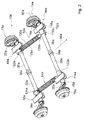
- FIG. 12 shows a vehicle 12a having a front vehicle section 58a and a rear vehicle section 60a with respect to a main travel direction 56a.
- the vehicle 12a is formed as a land vehicle in the present embodiment.
- the vehicle 12a is formed as a road vehicle in the present embodiment.
- the vehicle 12a is designed as a utility vehicle.
- the vehicle 12a is designed as a heavy goods vehicle with a maximum permissible mass over 1 tonne, However, it could also be formed accordingly by a trailer with a maximum permissible mass of more than 0.75 tons, preferably over 3.5 tons.
- the front vehicle section 58a comprises a drive unit with a drivable and steerable axle 62a and a driver cab 64a.
- the rear vehicle portion 60a includes a load frame with two side rails 66a, 68a.
- the longitudinal members 66a, 68a are arranged parallel to the main direction of travel 56a.
- the longitudinal members 66a, 68a are arranged in mirror image relative to a plane arranged centrally parallel to the main travel direction 56a.
- the rear vehicle section 60a has, in the present embodiment, an axle device 10a with two axles 14a, 16a.
- the axles 14a, 16a are formed as non-driven axles 14a, 16a.
- the axes 14a, 16a are arranged at least substantially parallel to one another.
- the axles 14a, 16a are arranged offset in parallel to one another in the main travel direction 56a.
- the axle device 10a has an axle stand.
- the axle device 10a has one of two different number of axles, for example one or three axles.
- the longitudinal members 66a, 68a are intended to transmit a weight of a payload, not shown, in particular to the axles 14a, 16a of the axle device 10a.
- the side members 66a, 68a are fixedly connected to the front vehicle portion 60a.
- the side members 66a, 68a are fixedly connected to a support unit of the front vehicle portion 58a.
- the rear vehicle section 60a has four wheels 70a, 72a, 74a, 76a in the present embodiment. It is conceivable that the rear vehicle section 60a has a different number of wheels, for example two or six wheels.
- a first one of the axles 14a and another one of the axles 16a are designed to be analogous to one another with regard to the features described below, for which reason only the first of the axles 14a will be described in more detail.
- the axis 14a is formed in the present embodiment as a non-steerable axis 14a.
- the axle 14a is provided for supporting two idler wheels 70a, 72a arranged on opposite sides of the vehicle 12a are.
- the wheels 70a, 72a are arranged in an assembled state on opposite sides of the axis 14a.
- the axle 14a is spatially arranged between a road surface and the side rails 66a, 68a of the vehicle 12a.
- the axis 14a has an axis of rotation 78a which is aligned at least substantially perpendicular to the main direction of travel 56a.
- the axle 14a is intended, in particular, to transmit a weight of the payload and / or the vehicle 12a from the longitudinal members 66a, 68a to the wheels 70a, 72a mounted on the axle 14a.
- the wheels 70a, 72a are intended to transmit in particular a weight of the payload and / or the vehicle 12a on a roadway.
- the first axle 14a has two trailing arms 18a, 20a which are each provided for mounting one of the wheels 70a, 72a of the vehicle 12a (cf. FIG. 2 and FIG. 3 ).
- the further axis 14a of the axle device 10a has two trailing arms 22a, 24a, which are each provided for mounting one of the wheels 74a, 76a of the vehicle 12a.
- the trailing arms 18a, 20a of the first axis 14a are arranged on two opposite sides of the axis 14a.
- a first of the trailing arm 18a is located to the left of an axle center with respect to the main travel direction 56a of the vehicle 12a.
- Another of the trailing arm 20a is arranged relative to the main direction of travel 56a of the vehicle 12a to the right of the center of the axle.
- the trailing arm 18a, 20a are formed analogously to each other, which is why in the following only the first of the trailing arm 18a is described in more detail.
- the first trailing arm 18a is elongate and has two opposite ends with respect to a main extension direction.
- the trailing arm 18a is pivotally supported at a first of the ends with respect to the rotational axis 78a of the axle 14a.
- the trailing arm 18a has a pivot point which is arranged on the axis of rotation 78a of the axle 14a.
- the mounted on the trailing arm 18a impeller 70a has an axis of rotation 80a.
- the rotation axis 80a of the impeller 70a is disposed at another one of the ends of the trailing arm 18a.
- the rotation axis 80a of the impeller 70a and the Fulcrum of the trailing arm 18a are spaced from each other.
- the trailing arm 18a is provided to be pivoted to change a distance between the impeller 70a supported on the trailing arm 18a and the side rails 66a, 68a.
- the axle 14a comprises two axle elements 26a, 28a, each of which is non-rotatably connected to one of the trailing arms 18a, 20a.
- the further axis 16a comprises two axle elements 30a, 32a.
- Each of the axle elements 26a, 28a is associated with one of the trailing arms 18a, 20a.
- the shaft elements 26a, 28a of the first axis 14a have a main extension in the direction of the axis of rotation 80a of the axis 14a.
- the axle elements 26a, 28a are arranged in alignment with each other.
- the axle elements 26a, 28a are arranged co-linear with each other.
- the axle elements 26a, 28a are provided for rotation about the axis of rotation 78a of the axle 14a.
- the shaft elements 26a, 28a have in the present embodiment, a same axial extent. It is conceivable that the axle elements 26a, 28a have a different axial extent. A first of the axle elements 26a is located to the left of the axle center with respect to the main travel direction 56a of the vehicle 12a. Another of the axle elements 28a is located to the right of the axle center relative to the main travel direction 56a of the vehicle 12a. In the present exemplary embodiment, the axle elements 26a, 28a are designed analogously to one another, for which reason only the first of the axle elements 26a will be described in more detail below.
- the axle element 26a is connected in a form-locking manner to the trailing arm 18a assigned to it.
- the axle element 26a and the trailing arm 18a are connected to each other by means of a bolt.
- the axle member 26a and the trailing arm 18a are bolted together. It is conceivable that the axle element 26a and the trailing arm 18a are connected to one another in a manner which seems suitable to a person skilled in the art, for example by material bonding.
- the axle element 26a has two ends arranged opposite one another in the axial direction.
- the axle member 26a has an outer end with respect to an axle center and with respect to a Axle center inside end.
- the axle member 26a is connected to the trailing arm 18a at the outer end.
- the axle element 26a is tubular.
- the axle element 26a is in the form of an elongated hollow cylinder.
- the axle member 26a is formed as an axle tube.
- the first axis 14a has a bearing unit 34a which is arranged axially between the axle elements 26a, 28a.
- the further axis 16a of the axle device 10a has a bearing unit 36a, which is arranged axially between the axle elements 30a, 32a of the further axle 16a.
- the bearing unit 34a of the first axis 14a is arranged centrally on the axis 14a.
- the bearing unit 34a is arranged with respect to an axial extent of the axis 14a in the center of the axle. It is conceivable that the bearing unit 34a is arranged off-center with respect to the axial extent of the axis 14a.
- the bearing unit 34a is arranged axially spaced from the axial center with respect to the axial extent.
- the bearing unit 34a is arranged between the axle elements 26a, 28a of the first axis 14a.
- the bearing unit 34a is arranged spatially between the axle elements 26a, 28a.
- the bearing unit 34a is structurally arranged between the axle elements 26a, 28a.
- the bearing unit 34a has a support and guide element 82a.
- the support and guide element 82a is arranged centrally in the storage unit 34a in the axial direction.
- the support and guide element 82a is arranged centrally in the radial direction in the bearing unit 34a.
- the support and guide element 82a is in the form of a thick-walled hollow cylinder.
- the support and guide element 82a is arranged coaxially with the axis 14a and with the axle elements 26a, 28a.
- the bearing unit 34a is provided to rotatably support each of the axle members 26a, 28a in the axial direction.
- the bearing unit 34a is provided to rotatably support the axle elements 26a, 28a in the axial direction against each other.
- the axle device 10a has a tension element 38a, which is provided to provide an at least substantially axially directed tensile force between the axle elements 26a, 28a (cf. FIG. 4 ).
- the tension element 38a is in formed in the present embodiment as a wire rope. It is conceivable that the tension member 38a is formed as another rope or in another form.
- the tensile force presses the first axle element 26a, the bearing unit 34a and the second axle element 28a together in an assembled state.
- the tensile force presses the first axle member 26a and the second axle member 28a onto the bearing unit 34a in an assembled state.
- the tension element 38a is elastic.
- the tensile force is designed as a clamping force.
- the bearing unit 34a has two bearing subunits 84a, 86a (cf. FIG. 5 ).
- the bearing subunits 84a, 86a are analogous to each other.
- the bearing subunits 84a, 86a are arranged in mirror image relative to one another in relation to an axial direction.
- the bearing subunits 84a, 86a are each assigned to one of the axle elements 26a, 28a.
- the bearing subunits 84a, 86a are arranged in mirror image relative to one another in relation to an axial direction.
- the bearing subunits 84a, 86a are mirror images of each other with respect to an axial direction.
- the bearing unit 34a has two bearings 40a, 42a which are each provided for rotatably supporting one of the axle elements 26a, 28a and for at least substantially absorbing the tensile force of the tension element 38a.
- the bearing subunits 84a, 86a are designed analogously to one another, which is why only a first of the bearing subunits 84a will be described in more detail below.
- the first bearing subunit 84a includes one of the bearings 40a of the bearing unit 34a.
- the bearing 40a is provided to rotatably support the axle unit 26a associated with the bearing subunit 84a.
- the bearing 40a is provided in the present embodiment to rotatably support the axle elements 26a, 28a against each other.
- the bearing subunit 84a includes a sleeve member 88a.
- the sleeve element 88a is connected to the axle element 26a, which is assigned to the bearing subunit 84a, at least in an axial direction, at least in a force-locking manner.
- the sleeve member 88a is connected to the shaft member 26a associated with the bearing subunit 84a at least in an axial direction positively connected.
- the sleeve member 88a and the shaft member 26a each have in the radial direction facing each other contact surfaces.
- the sleeve element 88a has a connection section 90a and a bearing section 92a in succession in the axial direction.
- the sleeve member 88a is attached to the axle member 26a in the present embodiment.
- the connecting portion 90a of the sleeve member 88a covers the shaft member 26a in a connecting portion.
- the shaft member 26a engages in the connecting portion in the sleeve member 88a.
- the bearing subunit 84a has a cross section perpendicular to the axis of rotation 78a of the shaft element 26a, in which the sleeve element 88a surrounds the axle element 26a.
- the axle element 26a has a wall 94a.
- a longitudinal section of the wall 94a has two radially opposite steps to a receptacle of the sleeve element 88a.
- the sleeve element 88a has an annular recess for receiving the shaft element 26a in the connection region. It is also conceivable that in an alternative embodiment, the sleeve member 88a engages the axle member 26a. It is also conceivable that the sleeve element 88a and the axle element 26a are connected to one another in a manner which appears expedient to the person skilled in the art, for example by material bonding.
- the bearing portion 92a of the sleeve member 88a is formed in the shape of a hollow cylinder.
- the connecting portion 90a of the sleeve member 88a is formed in the shape of a hollow cylinder.
- the bearing portion 92a has a larger diameter than the terminal portion 90a.
- the bearing portion 92a of the sleeve member 88a has a larger diameter than the terminal portion 90a.
- the sleeve member 88a has a wall. A longitudinal section of the wall has, at a transition between the bearing portion 92a and the connection portion 90a, two radially opposed steps.
- the bearing 40a is formed as an angular bearing.
- the bearing 40a has an outer ring 96a.
- the outer ring 96a of the bearing 40a is at least in the axial direction fixedly connected to the sleeve member 88a.
- the outer ring 96a of the bearing 40a has a conical tread.
- the outer ring 96a of the bearing 40a has an inner cone.
- the inner cone of the outer ring 96a is open to a side facing away from the axle 26a side.
- the inner cone tapers on a side facing the axle 26a.
- the bearing 40a has an inner ring 98a.
- the inner ring 98a of the bearing 40a is fixedly connected at least in the axial direction with the support and guide element 82a of the bearing unit 34a.
- the inner ring 98a has a conical tread.
- the inner ring 98a has an outer cone.
- the outer cone is open to a side facing away from the axle 26a
- the inner cone of the outer ring 96a has, in the present embodiment, a larger opening angle than the outer cone of the inner ring 98a.
- the bearing 40a has a plurality of rolling elements 100a, 102a.
- the rolling elements 100a, 102a are formed in the form of truncated cones.
- the bearing 40a is formed as a tapered roller bearing (see. FIG. 6 ).
- the rolling elements 100a, 102a are conical.
- the rolling elements 100a, 102a each have two axial ends with different diameters. In an assembled state, an axial end having a maximum diameter is disposed away from the shaft member 26a. An axial end having a minimum diameter is disposed facing the shaft member 26a.
- the rolling bodies 100a, 102a have a different shape and, for example, are cylindrical or spherical.
- the rolling bodies 100a, 102a each have an axis of rotation.
- the rotational axes of the rolling elements 100a, 102a are arranged obliquely to the axis of rotation of the axis 14a.
- the axes of rotation of the rolling elements 100a, 102a enclose an angle with the axis of rotation 78a of the axis 14a, which in the present
- Embodiment is open in a direction away from the axle 26a direction.
- the inner ring 98a of the bearing 40a is non-rotatably connected to the support and guide element 82a.
- the inner ring 98a of the bearing 40a is non-rotatably connected to an inner ring 98a of the bearing 40a of a further bearing subunit 86a of the bearing unit 34a.
- the inner ring 98a of the bearing 40a can be non-rotatably connected to the axle element 26a and the outer ring 96a of the bearing 40a can be non-rotatably connected to a support and guide element 82a.
- the rolling elements 100a, 102a may each have an axis of rotation which forms an angle with the axis 14a which is open in a direction facing the axle element 26a.
- the bearing subunit 86a can have two bearings, one of which, for example, is designed as a thrust bearing and another as a radial bearing. It is conceivable that the bearing unit 34a in a further alternative embodiment has a single bearing which supports the axle elements 26a, 28a against each other.
- the tension element 38a passes through the first axle element 26a in the axial direction.
- the tension element 38a passes through the further axle element 26a in the axial direction.
- the tension element 38a passes through the two axle elements 26a, 28a in the axial direction.
- the tension element 38a passes through the bearing unit 34a in the axial direction.
- the tension element 38a passes through the support and guide element 82a.
- the support and guide element 82a has a central bore in the axial direction. The bore is provided for receiving the tension element 38a.
- the support and guide element 82a is intended to support and / or guide the tension element 38a.
- An extension of the tension element 38a in the direction of the axis 14a corresponds to a sum of an extension of the first shaft element 26a in the direction of the axis 14a, an extension of the further shaft element 28a in the direction of the axis 14a and an extension of the bearing unit 34a in the direction of the axis 14a ,
- the axis 14a has two fixing elements 104a, 106a, which result in an axial fixation of the Traction element 38a are provided.
- the fixing elements 104a, 106a are each assigned to one of the axle elements 26a, 28a.
- the fixing elements 104a, 106a are each provided to transmit the pulling force provided by the tension element 38a to the axle element 26a, 28a assigned to the respective fixing element 104a, 106a.
- the tension element 38a has at its ends in each case a stop element 108a, 110a which is provided in each case for transmitting the tensile force of the tension element 38a to a respective fixing element 104a, 106a.
- the fixing elements 104a, 106a are each provided in the present exemplary embodiment to arrange in each case one end of the wire rope radially centered at one end of the associated axle element 26a, 28a.
- the axle device 10a has a bearing point 44a for a direct mounting of the first axle element 26a of the first axle 14a and a further bearing point 46a for a direct mounting of the further axle element 28a of the first axle 14a.
- the axle device 10a has a third bearing point 48a for a direct mounting of the first axle element 30a of the further axle 16a and a fourth bearing point 50a for a direct mounting of the further axle element 32a of the further axle 16a.
- the first axle member 26a of the first axle 14a is supported at the bearing 44a directly rotatably with respect to the load frame of the rear vehicle portion 60a.
- the first axle member 26a is pivotally supported against the load frame of the rear vehicle portion 60a.
- the further axle element 28a is mounted directly rotatable relative to the load frame of the rear vehicle section 60a at the further bearing point 46a.
- the further axle element 28a is pivotably mounted relative to the load frame of the rear vehicle section 60a.
- the bearing 44a and the other bearing 46a are provided to store the axle elements 26a, 28a independently of each other.
- the axle elements 26a, 28a are independently rotatably supported in a mounted state relative to the load frame of the rear vehicle portion 60a.
- the axle device 10a comprises a first axle bearing unit 112a, which supports the bearing 44a directly Storage of the first axle element 26a forms.
- the axle device 10a comprises a further axle bearing unit 114a, which forms the further bearing point 46a for a direct mounting of the further axle element 28a.
- the first axle bearing unit 112a is associated with the first axle element 26a.
- the further axle bearing unit 114a is assigned to the further axle element 28a.
- the axle bearing unit 112a and the further axle bearing unit 114a are formed separately from each other.
- the axle box unit 112a and the further axle box unit 114a are spaced apart from each other.
- axlebox units 112a, 114a are designed to be analogous to one another, so that only the first of the axlebox units 112a will be described in more detail below.
- the axle bearing unit 114a is designed as a bearing block.
- the axle bearing unit 114a has a fastener 116a for a fixed attachment to the load frame of the rear vehicle portion 60a.
- the fastening element 116a is provided in the present exemplary embodiment to be screwed to one element of the load frame, for example to one of the side members 66a. It is conceivable that the fastening element 116a is provided for another fastening, for example by welding, soldering or in another manner that appears appropriate to the person skilled in the art.
- the fastener 116a is formed as a plate.
- the fastener 116a is formed in the present embodiment as a metal plate.
- the axle bearing unit 114a has a two-part bearing block in the present exemplary embodiment.
- the bearing block is divided in the radial direction.
- an axial extent of the bearing 46a corresponds to an axial extent of the fastening element 116a of the axle bearing unit 114a.
- the axial extent of the bearing 46a is less than 90a mm in the present embodiment.
- the axle device 10a comprises four shock absorber units.
- the first axis 14a are associated with two shock absorber units.
- the further axis 16a are associated with two further shock absorber units.
- the shock absorber units are formed analogous to each other, which is why only a first of the shock absorber units is described in detail.
- the first shock absorber unit is assigned to the first axle element 26a, the first axle 14a.
- the first shock absorber unit is associated with the first trailing arm 18a.
- the shock absorber unit is intended to damp a pivotal movement of the associated axle element 26a and / or the associated trailing arm 18a.
- the shock absorber unit comprises a damping element, for example a hydraulic damping element, a mechanical damping element or another damping element which appears suitable to the person skilled in the art.
- the shock absorber unit is operatively disposed between the trailing arm 18a and the load frame.
- the shock absorber unit in particular operatively, be arranged between the associated trailing arm 18a and the bearing unit 44a.
- an element of the bearing unit 44a in particular the bearing block and / or the fastening element 116a, have an extension in the direction of travel, which corresponds to an extent of the trailing arm 18a in the direction of travel.
- the element of the bearing unit 44a may in particular be extended compared to the present embodiment.
- the axle device 10a comprises two elastically deformable connecting rod units 52a, 54a, which are respectively provided to couple a pivoting movement of one of the axle elements 26a, 28a of the first axle 14a with a pivoting movement of one of the axle elements 30a, 32a of the further axle 16a.
- the connecting rod units 52a, 54a are designed to support a torque acting on one of the axle elements 26a, 28a of the first axle 14a with respect to an axle member 30a, 32a of the further axle 16a and vice versa a torque that on one of the axle elements 30a, 32a of the other Axis 16a acts to support against a shaft member 26a, 28a of the first axis 14a.
- the connecting rod units 52a, 54a each have a main extension direction.
- the connecting rod units 52a, 54a are arranged in an assembled state at least substantially parallel to one another.
- the connecting rods 52a, 54a are in an assembled state arranged at least substantially parallel to the main direction of travel 56a.
- the axle device 10a comprises four lever elements 118a, 120a, 122a, 124a, which are each provided for connecting a shaft element 26a, 28a, 30a, 32a to a connecting rod unit 52a, 54a.
- the lever elements 118a, 120a, 122a, 124a are each assigned to one of the axle elements 26a, 28a, 30a, 32a.
- a first one of the lever members 118a connects, in an assembled state, the first shaft member 26a of the first shaft 14a to a first one of the connecting rods 52a.
- a second of the lever elements 120a connects, in an assembled state, the further axle element 28a of the first axle 14a with a further one of the connecting rod units 54a.
- a third of the lever elements 122a connects the first axle element 30a of the further axle 16a to the first connecting rod unit 52a in an assembled state.
- a fourth of the lever elements 124a connects, in an assembled state, the further axle element 32a of the further axle 16a with the further connecting rod unit 54a.
- the lever elements 118a, 120a, 122a, 124a are each non-rotatably connected to the associated axle element 26a, 28a, 30a, 32a.
- the connecting rod units 52a, 54a are designed to be analogous to one another, for which reason only the first connecting rod unit 52a will be described in more detail below.
- the first connecting rod unit 52a has two tube elements 126a, 128a which are movable relative to each other in the main direction of extension of the connecting rod unit 52a.
- the connecting rod unit 52a has a return member 130a operatively disposed between the tubular members 126a, 128a.
- the return element 130a is formed in the present embodiment as a helical spring, which surrounds the tube elements 126a, 128a in an assembled state.
- the tube elements 126a, 128a are provided for a damped translational movement against each other, which leads to a change in length of the connecting rod unit 52a.
- the return element 130a is intended to counteract the change in length of the connecting rod unit 52a.
- the connecting rod unit 52a has two ends facing away from one another in the main extension direction.
- the connecting rod unit 52a is rotatably connected to the first lever member 118a at a first one of the ends.
- the connecting rod unit 52a has, at the first end, an axis of rotation 78a with respect to the first lever element 118a with which it is connected.
- the rotation axis 78a is disposed in parallel to the rotation axis 78a of the first shaft member 26a, to which the connecting rod unit 52a is connected at the first end by means of the first lever member 118a.
- a second end of the connecting rod unit 52a is connected to the first axle member 30a of the further axle 16a by means of the second lever member 120a.
- the connecting rod unit 52a has at the second end an axis of rotation with respect to the second lever element 118a, with which it is connected.
- the rotation axis is arranged parallel to the rotation axis of the shaft member 30a to which the connecting rod unit 52a is connected at the second end.
- the connecting rod unit 52a is designed to connect axle elements 26a, 30a of different axles 14a, 16a to one another.
- the lever elements 118a, 120a, 122a, 124a each have a lever arm direction, which is aligned at least substantially perpendicular to the axis 14a, 16a, with which the respective lever element 118a, 120a, 122a, 124a is non-rotatably connected.
- the lever arm direction has, from the axis of rotation of the axle element 26a, 28a, 30a, 32a, to which the lever element 118a, 120a, 122a, 124a is connected, to the axis of rotation of the connecting rod unit 52a, 54a to which the lever element 118a, 120a, 122a, 124a is connected is.
- the lever arm direction is aligned at least substantially perpendicular to the main direction of travel 56a.
- the lever arm directions of lever elements 118a, 120a, 122a, 124a, which are assigned to a same connecting rod unit 52a, 54a, are arranged at least substantially opposite to one another.
- the first connecting rod unit 52a is provided for coupling a pivoting movement of the first axle element 26a of the first axle 14a connected to the connecting rod unit 52a and a pivoting movement of the first axle member 30a of the further axle 16a connected to the connecting rod unit 52a.
- the axle element 26a pivots about its axis of rotation 78a in a first direction of rotation.
- the first lever element 118a translates the pivoting movement into an at least substantially translatory movement of the first connecting rod unit 52a.
- the connecting rod unit 52a transmits the pivotal movement of the first axle element 26a of the first axle 14a in a damped manner onto the first axle element 30a of the further axle 16a.
- the second lever element 120a translates the at least substantially translatory movement of the first connecting rod unit 52a into a pivoting movement of the first axle element 30a of the further axle 16a.
- the pivoting movement of the first shaft element 30a of the further axis 16a has a direction of rotation which is opposite to the direction of rotation of the pivoting movement of the first shaft element 30a of the first axis 16a.
- FIG. 7 shows a further embodiment of the axle device 10b for a vehicle not shown in detail.
- the axle device 10b for a vehicle not shown in detail.
- Constant components are generally numbered with the same reference numerals, the letters a, b and c are added to distinguish the embodiments of the reference numerals.
- the axle device 10b has only one axis 14b.
- the axis 14b has, analogously to the preceding embodiment, two trailing arms 18b, 20b, which are each provided for supporting an impeller.
- the vehicle includes a load frame, not shown, which is intended to transmit a weight of a payload not shown in particular on the axis 14b of the axle device 10b.
- the axis 14b is formed as a non-steerable axis 14b.
- the axis 14b is provided for a bearing of two wheels, which are arranged on opposite sides of the vehicle.
- the wheels are arranged in an assembled state on opposite sides of the axis 14b.
- the axle 14b has an axis of rotation 78b which is aligned at least substantially perpendicular to a main travel direction 56b of the vehicle.
- the trailing arm 18b, 20b of the axis 14b are arranged on two opposite sides of the axis 14b.
- a first of the trailing arm 18b is arranged on the left of an axle center relative to the main driving direction 56b of the vehicle.
- Another of the trailing arm 20b is arranged relative to the main driving direction 56b of the vehicle to the right of the axle center.
- the trailing arm 18b, 20b are formed analogously to each other, which is why only the first of the trailing arm 18b will be described in more detail below.
- the first trailing arm 18b is elongated and has two opposite ends with respect to a main extension direction.
- the trailing arm 18b is pivotally mounted on a first of the ends with respect to the axis of rotation 78b of the axle 14b.
- the trailing arm 18b has a pivot point which is arranged on the axis of rotation 78b of the axis 14b.
- the mounted on the trailing arm 18b impeller has a rotation axis 80b.
- the rotation axis 80b of the impeller is disposed at another one of the ends of the trailing arm 18b.
- the axis of rotation 80b of the impeller and the pivot point of the trailing arm 18b are spaced from each other.
- the trailing arm 18b is intended to be pivoted to a change in a distance between the mounted on the trailing arm 18b impeller and the load frame of the vehicle.
- the axle 14b comprises two axle elements 26b, 28b, each of which is non-rotatably connected to one of the trailing arms 18b, 20b.
- Each of the axle elements 26b, 28b is associated with one of the trailing arms 18b, 20b.
- the axle elements 26b, 28b of the axle 14b have a main extension in the direction of the axis of rotation 80b of the axle 14b.
- the axle elements 26b, 28b are arranged in alignment with each other.
- the axle elements 26b, 28b are arranged colinear with each other.
- the Axle elements 26b, 28b are provided for rotation about the axis of rotation 78b of the axle 14b.
- the trailing arm 18b is pivotally supported by means of the axle element 26b.
- the axle elements 26b, 28b are designed to be analogous to one another, so that only the first of the axle elements 26b will be described in more detail below.
- the axle element 26b is connected in a form-fitting manner to the trailing arm 18b assigned to it.
- the axle element 26b and the trailing arm 18b are connected to each other by means of a bolt.
- the axle element 26b has two ends arranged opposite one another in the axial direction.
- the axle element 26b has an outer end with respect to an axle center and an inner end with respect to an axle center.
- the axle member 26b is connected to the trailing arm 18b at the outer end.
- the axle 14b has a bearing unit 34b, which is arranged axially between the axle elements 26b, 28b.
- the bearing unit 34b of the axle 14b is arranged centrally on the axle 14b.
- the bearing unit 34b is arranged with respect to an axial extent of the axis 14b in the center of the axle.
- the bearing unit 34b is arranged between the axle elements 26b, 28b of the axle 14b.
- the bearing unit 34b is arranged spatially between the axle elements 26b, 28b.
- the bearing unit 34b is structurally arranged between the axle elements 26b, 28b.
- the axle device 10b has a tension element, not shown in more detail, which is provided to provide an at least substantially axially directed tensile force between the axle elements 26b, 28b.
- the tensile force presses the first axle element 26b, the bearing unit 34b and the second axle element 28b in an assembled state against each other.
- the tensile force presses the first axle member 26b and the second axle member 28b onto the bearing unit 34b in an assembled state.
- the tension element is elastic.
- the tensile force is designed as a clamping force.
- the tension element passes through the axle elements in axial direction.
- the bearing unit 34b is designed analogously to the preceding exemplary embodiment.
- the bearing unit 34b has two bearings, not shown in detail, which are each provided to each rotatably support one of the axle elements 26b, 28b, and to receive the tensile force of the tension element.
- the bearings are each formed as an angular bearing analogous to the preceding embodiment.
- the axle device 10b has a bearing point 44b for a direct mounting of the first axle element 26b of the axle 14b and a further bearing point 46b for a direct mounting of the further axle element 28b of the axle 14b.
- first axle element 26b of the axle 14b is mounted on the bearing 44b directly rotatable relative to the load frame.
- the first axle member 26b is pivotally supported relative to the load frame of the vehicle.
- the further axle element 28b is mounted directly rotatable relative to the load frame of the vehicle at the further bearing point 46b.
- the further axle element 28b is pivotally mounted relative to the load frame of the vehicle.
- the bearing 44b and the further bearing 46b are provided to store the axle elements 26b, 28b independently of each other with respect to the load frame.
- the axle device 10b comprises a first axle bearing unit 112b, which forms the bearing point 44b for direct mounting of the first axle element 26b.
- the axle device 10b comprises a further axle bearing unit 114b, which forms the further bearing point 46b for direct mounting of the further axle element 28b.
- the first axle bearing unit 112b is assigned to the first axle element 26b.
- the further axle bearing unit 114b is assigned to the further axle element 28b.
- the axle bearing unit 112b and the further axle bearing unit 114b are formed separately from each other.
- the axle box unit 112b and the further axle box unit 114b are spaced apart from each other.
- the axlebox units 112b, 114b are designed analogously to one another, for which reason only the first of the axlebox units 112b will be described in more detail below.
- the axle bearing unit 114b is designed as a bearing block.
- the Axle bearing unit 114b has a fastener 116b for a fixed attachment to the load frame of the rear vehicle portion 60b.
- the fastening element 116b is provided in the present exemplary embodiment to be screwed to an element of the load frame, for example to one of the longitudinal members.
- the axle device 10b comprises two shock absorber units 132b, 134b. A first of the shock absorber units 132b is associated with the first axle member 26b. Another of the shock absorber units 134b is assigned to the further axle element 28b.
- the axle device 10b comprises two lever elements 118b, 120b. A first of the lever elements 118b is associated with the first axle element 26b. Another of the lever elements 120b is assigned to the further axle element 28b.
- the shock absorber units 132b, 134b are designed to be analogous to one another, for which reason only the first shock absorber unit 132b will be described in more detail below.
- the shock absorber unit 132b is provided for damping and / or springing a pivot movement of the associated axle element 26b and / or the associated trailing arm 18b.
- the shock absorber unit 132b is operatively disposed between the axle member 28b and the load frame of the vehicle.
- the first lever element 118b is non-rotatably connected to the first axle element 28b.
- the lever member 118b has two flat struts 136b, 138b, and a support surface spaced from the shaft member 28b.
- the struts 136b, 138b are provided to connect the axle member 28b to the support surface.
- the shock absorber unit 132b has an effective axis 140b, which is aligned in an assembled state at least substantially perpendicular to the support surface.
- the effective axis 140b of the shock absorber unit 132b is disposed perpendicular to the axis 14b.
- the effective axis 140b of the shock absorber unit 132b is spaced from the axis 14b.
- the lever member 118b is provided to torque and / or to transmit a rotational movement between the axle element 28b and the support surface.
- the lever element 118b is provided to translate a pivoting movement of the axle element 26b into a translatory movement.
- the lever element 118b shortens or lengthens the shock absorber unit 132b in the direction of the effective axis 140b when the trailing arm 18b pivots.
- the shock absorber unit 132b comprises at least one restoring element, at least one damping element and at least one cylindrical bellows element 142b.
- the bellows 142b forms an envelope of the shock absorber unit 132b in an assembled state.
- the restoring element is designed, for example, as a mechanical spring, such as a helical spring, or as a gas spring or as another elastic element that appears suitable for a person skilled in the art.
- the restoring element is provided to provide a restoring force, which counteracts a change in length in the direction of the effective axis 140b of the shock absorber unit 132b.
- the damping element is designed, for example, as a mechanical damping element, a pneumatic damping element, a hydraulic damping element or the like.
- the damping element is intended to dampen in particular a jerky change in length. It is conceivable that the return element and the damping element are integrally formed with each other.
- FIG. 8 shows a perspective view of an alternative axle device with two axes 14c, 16c.
- the axes 14c, 16c have the same structure, so that the following description can be limited to the axis 16c.
- the axle 16c has a bearing unit 36c which is arranged between two axle elements 30c, 32c of the axle 16c and which pivotably connects the axle elements 30c, 32c relative to one another.
- the bearing unit 36c has a clamping unit 144c which is provided to brace the axle elements 30c, 32c and bearings 40c, 42c of the bearing unit 36c ( Fig. 9 ).
- the clamping unit 144c has a clamping element 146c, which is arranged in a coupling region 148c of the axle elements 30c, 32c.
- the clamping element 146c is formed by an inner bolt 154c of the clamping unit 144c and has a thread 152c which is arranged in the coupling region 148c of the axle elements 30c, 32c.
- the inner bolt 154c is rotatably connected to the axle member 32c.
- the inner bolt 154c is fastened to an end of the axle element 32c facing the axle element 30c.
- the inner bolt 154c is partially inserted into the shaft member 32c.
- the axle element 32c and the inner bolt 154c are non-rotatably connected via a welded connection.
- the thread 152c is arranged on an end of the inner bolt 154c facing away from the axle element 32c.
- the inner bolt 154c is stepped in the direction away from the shaft member 32c direction with a decreasing diameter.
- the bearings 40c, 42c of the bearing unit 36c are arranged on the inner bolt 154c.
- the bearings 40c, 42c are formed as double row angular contact ball bearings.
- the bearings 40c, 42c are mounted in a portion of the inner bolt 154c thereon, which has an outer diameter smaller than an outer diameter of the shaft member 32c.
- the outer diameter of the inner bolt 154c in this area is smaller than an inner diameter of the pipe-formed shaft member 32c, whereby the bearings 40c, 42c can be advantageously integrated.
- the bearings 40c, 42c of the bearing unit 36c and the axle elements 30c, 32c are clamped together.
- a nut 164c is screwed, which loads an inner ring of the bearing 40c in the direction of the shaft member 32c and applies a clamping force on this.
- the clamping force is transmitted via a spacer inner ring 166c on an inner ring of the bearing 42c, wherein the inner ring of the bearing 42c is supported on a shoulder 174c of the inner bolt 154c.
- a sleeve 168c in which the inner bolt 154c is mounted in the mounted state, is fastened to an end of the shaft element 30c facing the axle element 32c is inserted.
- the sleeve 168c and / or the inner bolt 154c could also be formed at least partially in one piece with the axle elements 30c, 32c.
- the sleeve 168c has, in a coupling region with the axle element 30c, a larger outer diameter than the axle element 30c and is pushed onto the axle element 30c.
- the sleeve 168c outer races of the bearings 40c, 42c are supported radially outwardly.
- the sleeve 168c has a screw connection, namely at the end of the sleeve 168c a disc 170c is screwed, which loads the outer rings of the bearing 42c in the direction of the shaft member 30c and applies a clamping force to it.
- the clamping force is transmitted via a spacer outer ring 172c on the outer ring of the bearing 40c, wherein the outer ring of the bearing 40c is supported on a shoulder 176c on the inner periphery of the sleeve 168c.
- the axle device further comprises connecting rods 52c, 54c, 156c, 158c, which are provided for coupling pivoting movements of the axle elements 26c, 28c, 30c, 32c to other units 160c, 162c in a sprung and damped manner.
- the units 160c, 162c are formed by cross members, which are arranged between longitudinal members 66c, 68c.
- the connecting rod units 52c, 54c, 156c, 158c comprise helical compression springs and gas dampers. In principle, however, other conceivable to those skilled in the useful springs and dampers are conceivable, such as air springs, leaf springs, oil dampers, etc.
Landscapes
- Engineering & Computer Science (AREA)
- Mechanical Engineering (AREA)
- Vehicle Body Suspensions (AREA)
- Rolling Contact Bearings (AREA)
Applications Claiming Priority (1)
| Application Number | Priority Date | Filing Date | Title |
|---|---|---|---|
| DE102015112161.1A DE102015112161A1 (de) | 2015-07-24 | 2015-07-24 | Achsvorrichtung |
Publications (2)
| Publication Number | Publication Date |
|---|---|
| EP3121035A1 true EP3121035A1 (fr) | 2017-01-25 |
| EP3121035B1 EP3121035B1 (fr) | 2019-03-20 |
Family
ID=56511356
Family Applications (1)
| Application Number | Title | Priority Date | Filing Date |
|---|---|---|---|
| EP16180169.1A Not-in-force EP3121035B1 (fr) | 2015-07-24 | 2016-07-19 | Dispositif d'essieu |
Country Status (2)
| Country | Link |
|---|---|
| EP (1) | EP3121035B1 (fr) |
| DE (1) | DE102015112161A1 (fr) |
Families Citing this family (1)
| Publication number | Priority date | Publication date | Assignee | Title |
|---|---|---|---|---|
| DE102024205360A1 (de) * | 2024-06-11 | 2025-12-11 | Zf Friedrichshafen Ag | Mehrteilige Achsbrücke für ein Nutzfahrzeug |
Citations (11)
| Publication number | Priority date | Publication date | Assignee | Title |
|---|---|---|---|---|
| US3601426A (en) * | 1968-11-13 | 1971-08-24 | Peugeot | Vehicle rear assembly |
| DE1780130A1 (de) * | 1968-08-05 | 1972-01-05 | Maschb Knott Eggstaett Valenti | Tandem-Fahrgestell |
| FR2154297A1 (fr) * | 1971-09-27 | 1973-05-11 | Citroen Sa | |
| FR2544259A1 (fr) * | 1983-04-12 | 1984-10-19 | Renault | Suspension arriere a roues independantes pour vehicule automobile |
| DE3535589C1 (de) * | 1985-10-05 | 1987-01-02 | Hans-Hermann Sieben | Radaufhaengung fuer absenkbare Fahrzeugaufbauten,insbesondere fuer Anhaenger,frontangetriebene LKW(Bus-Kombi),Wohnmobile |
| FR2805776A1 (fr) * | 2000-03-02 | 2001-09-07 | Michelin & Cie | Essieu souple pour vehicule automobile, a dispositif anti- roulis perfectionne |
| WO2002022384A1 (fr) * | 2000-09-12 | 2002-03-21 | Compagnie Generale Des Etablissements Michelin-Michelin & Cie | Procede de fixation d'au moins un insert de guidage entre deux tubes coaxiaux, notamment dans un dispositif anti-roulis de vehicule automobile |
| FR2840561A1 (fr) * | 2002-06-10 | 2003-12-12 | Auto Chassis Int | Essieu arriere souple de vehicule a double bras et element de liaison deformable en torsion |
| FR2902698A1 (fr) * | 2006-06-23 | 2007-12-28 | Michelin Soc Tech | Essieu suspendu pour vehicule |
| DE102009040204A1 (de) * | 2009-09-07 | 2011-03-17 | Fgs Gmbh | Fahrgestellvorrichtung mit einer Achslifteinheit |
| US20140131969A1 (en) * | 2012-11-14 | 2014-05-15 | Oshkosh Corporation | Co-axial sway bar for a suspension system |
Family Cites Families (5)
| Publication number | Priority date | Publication date | Assignee | Title |
|---|---|---|---|---|
| DE1809698A1 (de) * | 1968-11-19 | 1970-06-04 | Volkswagenwerk Ag | Kraftfahrzeugachse mit durch Laengslenker gefuehrten Raedern |
| FR2528365A1 (fr) * | 1982-06-15 | 1983-12-16 | Aerospatiale | Suspension a bras oscillants pour un train de deux roues d'un vehicule et systeme de rappel elastique et de couplage antiroulis pour une telle suspension |
| IT1160103B (it) * | 1983-01-14 | 1987-03-04 | Fiat Auto Spa | Sospensione posteriore per autoveicoli a ruote semi indipendenti con traversa di rotazione |
| AUPQ934600A0 (en) * | 2000-08-11 | 2000-09-07 | Kinetic Pty Limited | Hydraulic suspension system for a vehicle |
| GB2460244A (en) * | 2008-05-21 | 2009-11-25 | Alan Bryn Bird | Vehicle suspension with linked arms |
-
2015
- 2015-07-24 DE DE102015112161.1A patent/DE102015112161A1/de not_active Withdrawn
-
2016
- 2016-07-19 EP EP16180169.1A patent/EP3121035B1/fr not_active Not-in-force
Patent Citations (11)
| Publication number | Priority date | Publication date | Assignee | Title |
|---|---|---|---|---|
| DE1780130A1 (de) * | 1968-08-05 | 1972-01-05 | Maschb Knott Eggstaett Valenti | Tandem-Fahrgestell |
| US3601426A (en) * | 1968-11-13 | 1971-08-24 | Peugeot | Vehicle rear assembly |
| FR2154297A1 (fr) * | 1971-09-27 | 1973-05-11 | Citroen Sa | |
| FR2544259A1 (fr) * | 1983-04-12 | 1984-10-19 | Renault | Suspension arriere a roues independantes pour vehicule automobile |
| DE3535589C1 (de) * | 1985-10-05 | 1987-01-02 | Hans-Hermann Sieben | Radaufhaengung fuer absenkbare Fahrzeugaufbauten,insbesondere fuer Anhaenger,frontangetriebene LKW(Bus-Kombi),Wohnmobile |
| FR2805776A1 (fr) * | 2000-03-02 | 2001-09-07 | Michelin & Cie | Essieu souple pour vehicule automobile, a dispositif anti- roulis perfectionne |
| WO2002022384A1 (fr) * | 2000-09-12 | 2002-03-21 | Compagnie Generale Des Etablissements Michelin-Michelin & Cie | Procede de fixation d'au moins un insert de guidage entre deux tubes coaxiaux, notamment dans un dispositif anti-roulis de vehicule automobile |
| FR2840561A1 (fr) * | 2002-06-10 | 2003-12-12 | Auto Chassis Int | Essieu arriere souple de vehicule a double bras et element de liaison deformable en torsion |
| FR2902698A1 (fr) * | 2006-06-23 | 2007-12-28 | Michelin Soc Tech | Essieu suspendu pour vehicule |
| DE102009040204A1 (de) * | 2009-09-07 | 2011-03-17 | Fgs Gmbh | Fahrgestellvorrichtung mit einer Achslifteinheit |
| US20140131969A1 (en) * | 2012-11-14 | 2014-05-15 | Oshkosh Corporation | Co-axial sway bar for a suspension system |
Also Published As
| Publication number | Publication date |
|---|---|
| DE102015112161A1 (de) | 2017-01-26 |
| EP3121035B1 (fr) | 2019-03-20 |
Similar Documents
| Publication | Publication Date | Title |
|---|---|---|
| EP1193087A2 (fr) | Suspension de roue pour véhicules automobiles | |
| EP2517905A1 (fr) | Agencement de ressort pour suspensions de roues de véhicules automobiles | |
| DE102016220786B4 (de) | Hinterradaufhängung für Kraftfahrzeuge | |
| EP0464412B1 (fr) | Suspension pneumatique à bras longitudinaux | |
| DE2027885A1 (de) | Achsaufhängung, insbesondere Hinterachs aufhangung von Kraftfahrzeugen | |
| DE102011086480B4 (de) | Achseinheit für Nutzfahrzeuge | |
| EP1154908B1 (fr) | Suspension pour essieu rigide de vehicule | |
| DE3233878C2 (fr) | ||
| DE102006061984B3 (de) | Radaufhängung für ein Kraftfahrzeug | |
| EP2780182B1 (fr) | Essieu rigide à suspension pneumatique | |
| EP4598758A1 (fr) | Système de suspension de roue de véhicule à moteur, et véhicule à moteur | |
| EP3121035B1 (fr) | Dispositif d'essieu | |
| DE102017211277B4 (de) | Radaufhängung für ein Kraftfahrzeug | |
| DE102018207616B4 (de) | Radaufhängung für ein Kraftfahrzeug | |
| EP0464415B1 (fr) | Suspension à bras longitudinaux pour véhicules à moteur et remorques | |
| DE102005013374B4 (de) | Halterung für einen um eine Schwenkachse schwenkbaren Lenker einer Radaufhängung eines Fahrzeugs | |
| DE102021201756A1 (de) | Radträger für eine Kraftfahrzeugradaufhängung und Radträgerbaukastensystem | |
| DE102020113865A1 (de) | Radaufhängung | |
| DE10029881B4 (de) | Gabelstapler | |
| DE1219812B (de) | Radaufhaengung fuer Kraftfahrzeuge | |
| DE3115611A1 (de) | Radaufhaengung fuer ein kraftfahrzeug | |
| DE102012009365A1 (de) | Hinterachse für ein Kraftfahrzeug | |
| EP0993382A1 (fr) | Suspension d'essieu pour essieux rigides de vehicules | |
| DE102009053125A1 (de) | Einrichtung zur aktiven Höhenverstellung einer Karosserie eines Fahrzeuges | |
| DE102014200420A1 (de) | Einzelradaufhängung sowie Hinterachsmodul mit Einzelradaufhängungen für ein Fahrzeug und entsprechend ausgestattetes Fahrzeug |
Legal Events
| Date | Code | Title | Description |
|---|---|---|---|
| PUAI | Public reference made under article 153(3) epc to a published international application that has entered the european phase |
Free format text: ORIGINAL CODE: 0009012 |
|
| STAA | Information on the status of an ep patent application or granted ep patent |
Free format text: STATUS: THE APPLICATION HAS BEEN PUBLISHED |
|
| AK | Designated contracting states |
Kind code of ref document: A1 Designated state(s): AL AT BE BG CH CY CZ DE DK EE ES FI FR GB GR HR HU IE IS IT LI LT LU LV MC MK MT NL NO PL PT RO RS SE SI SK SM TR |
|
| AX | Request for extension of the european patent |
Extension state: BA ME |
|
| STAA | Information on the status of an ep patent application or granted ep patent |
Free format text: STATUS: REQUEST FOR EXAMINATION WAS MADE |
|
| 17P | Request for examination filed |
Effective date: 20170721 |
|
| RBV | Designated contracting states (corrected) |
Designated state(s): AL AT BE BG CH CY CZ DE DK EE ES FI FR GB GR HR HU IE IS IT LI LT LU LV MC MK MT NL NO PL PT RO RS SE SI SK SM TR |
|
| R17P | Request for examination filed (corrected) |
Effective date: 20170721 |
|
| STAA | Information on the status of an ep patent application or granted ep patent |
Free format text: STATUS: EXAMINATION IS IN PROGRESS |
|
| 17Q | First examination report despatched |
Effective date: 20180116 |
|
| GRAP | Despatch of communication of intention to grant a patent |
Free format text: ORIGINAL CODE: EPIDOSNIGR1 |
|
| STAA | Information on the status of an ep patent application or granted ep patent |
Free format text: STATUS: GRANT OF PATENT IS INTENDED |
|
| INTG | Intention to grant announced |
Effective date: 20181009 |
|
| GRAS | Grant fee paid |
Free format text: ORIGINAL CODE: EPIDOSNIGR3 |
|
| GRAA | (expected) grant |
Free format text: ORIGINAL CODE: 0009210 |
|
| STAA | Information on the status of an ep patent application or granted ep patent |
Free format text: STATUS: THE PATENT HAS BEEN GRANTED |
|
| AK | Designated contracting states |
Kind code of ref document: B1 Designated state(s): AL AT BE BG CH CY CZ DE DK EE ES FI FR GB GR HR HU IE IS IT LI LT LU LV MC MK MT NL NO PL PT RO RS SE SI SK SM TR |
|
| REG | Reference to a national code |
Ref country code: GB Ref legal event code: FG4D Free format text: NOT ENGLISH |
|
| REG | Reference to a national code |
Ref country code: CH Ref legal event code: EP |
|
| REG | Reference to a national code |
Ref country code: DE Ref legal event code: R096 Ref document number: 502016003792 Country of ref document: DE |
|
| REG | Reference to a national code |
Ref country code: AT Ref legal event code: REF Ref document number: 1110165 Country of ref document: AT Kind code of ref document: T Effective date: 20190415 |
|
| REG | Reference to a national code |
Ref country code: IE Ref legal event code: FG4D Free format text: LANGUAGE OF EP DOCUMENT: GERMAN |
|
| REG | Reference to a national code |
Ref country code: CH Ref legal event code: NV Representative=s name: DAUB PATENTANWALTSKANZLEI, CH |
|
| REG | Reference to a national code |
Ref country code: NL Ref legal event code: MP Effective date: 20190320 |
|
| PG25 | Lapsed in a contracting state [announced via postgrant information from national office to epo] |
Ref country code: LT Free format text: LAPSE BECAUSE OF FAILURE TO SUBMIT A TRANSLATION OF THE DESCRIPTION OR TO PAY THE FEE WITHIN THE PRESCRIBED TIME-LIMIT Effective date: 20190320 Ref country code: SE Free format text: LAPSE BECAUSE OF FAILURE TO SUBMIT A TRANSLATION OF THE DESCRIPTION OR TO PAY THE FEE WITHIN THE PRESCRIBED TIME-LIMIT Effective date: 20190320 Ref country code: FI Free format text: LAPSE BECAUSE OF FAILURE TO SUBMIT A TRANSLATION OF THE DESCRIPTION OR TO PAY THE FEE WITHIN THE PRESCRIBED TIME-LIMIT Effective date: 20190320 Ref country code: NO Free format text: LAPSE BECAUSE OF FAILURE TO SUBMIT A TRANSLATION OF THE DESCRIPTION OR TO PAY THE FEE WITHIN THE PRESCRIBED TIME-LIMIT Effective date: 20190620 |
|
| REG | Reference to a national code |
Ref country code: LT Ref legal event code: MG4D |
|
| PG25 | Lapsed in a contracting state [announced via postgrant information from national office to epo] |
Ref country code: GR Free format text: LAPSE BECAUSE OF FAILURE TO SUBMIT A TRANSLATION OF THE DESCRIPTION OR TO PAY THE FEE WITHIN THE PRESCRIBED TIME-LIMIT Effective date: 20190621 Ref country code: HR Free format text: LAPSE BECAUSE OF FAILURE TO SUBMIT A TRANSLATION OF THE DESCRIPTION OR TO PAY THE FEE WITHIN THE PRESCRIBED TIME-LIMIT Effective date: 20190320 Ref country code: RS Free format text: LAPSE BECAUSE OF FAILURE TO SUBMIT A TRANSLATION OF THE DESCRIPTION OR TO PAY THE FEE WITHIN THE PRESCRIBED TIME-LIMIT Effective date: 20190320 Ref country code: LV Free format text: LAPSE BECAUSE OF FAILURE TO SUBMIT A TRANSLATION OF THE DESCRIPTION OR TO PAY THE FEE WITHIN THE PRESCRIBED TIME-LIMIT Effective date: 20190320 Ref country code: NL Free format text: LAPSE BECAUSE OF FAILURE TO SUBMIT A TRANSLATION OF THE DESCRIPTION OR TO PAY THE FEE WITHIN THE PRESCRIBED TIME-LIMIT Effective date: 20190320 Ref country code: BG Free format text: LAPSE BECAUSE OF FAILURE TO SUBMIT A TRANSLATION OF THE DESCRIPTION OR TO PAY THE FEE WITHIN THE PRESCRIBED TIME-LIMIT Effective date: 20190620 |
|
| PG25 | Lapsed in a contracting state [announced via postgrant information from national office to epo] |
Ref country code: IT Free format text: LAPSE BECAUSE OF FAILURE TO SUBMIT A TRANSLATION OF THE DESCRIPTION OR TO PAY THE FEE WITHIN THE PRESCRIBED TIME-LIMIT Effective date: 20190320 Ref country code: ES Free format text: LAPSE BECAUSE OF FAILURE TO SUBMIT A TRANSLATION OF THE DESCRIPTION OR TO PAY THE FEE WITHIN THE PRESCRIBED TIME-LIMIT Effective date: 20190320 Ref country code: CZ Free format text: LAPSE BECAUSE OF FAILURE TO SUBMIT A TRANSLATION OF THE DESCRIPTION OR TO PAY THE FEE WITHIN THE PRESCRIBED TIME-LIMIT Effective date: 20190320 Ref country code: RO Free format text: LAPSE BECAUSE OF FAILURE TO SUBMIT A TRANSLATION OF THE DESCRIPTION OR TO PAY THE FEE WITHIN THE PRESCRIBED TIME-LIMIT Effective date: 20190320 Ref country code: EE Free format text: LAPSE BECAUSE OF FAILURE TO SUBMIT A TRANSLATION OF THE DESCRIPTION OR TO PAY THE FEE WITHIN THE PRESCRIBED TIME-LIMIT Effective date: 20190320 Ref country code: PT Free format text: LAPSE BECAUSE OF FAILURE TO SUBMIT A TRANSLATION OF THE DESCRIPTION OR TO PAY THE FEE WITHIN THE PRESCRIBED TIME-LIMIT Effective date: 20190720 Ref country code: AL Free format text: LAPSE BECAUSE OF FAILURE TO SUBMIT A TRANSLATION OF THE DESCRIPTION OR TO PAY THE FEE WITHIN THE PRESCRIBED TIME-LIMIT Effective date: 20190320 Ref country code: SK Free format text: LAPSE BECAUSE OF FAILURE TO SUBMIT A TRANSLATION OF THE DESCRIPTION OR TO PAY THE FEE WITHIN THE PRESCRIBED TIME-LIMIT Effective date: 20190320 |
|
| PGFP | Annual fee paid to national office [announced via postgrant information from national office to epo] |
Ref country code: FR Payment date: 20190724 Year of fee payment: 4 |
|
| PG25 | Lapsed in a contracting state [announced via postgrant information from national office to epo] |
Ref country code: PL Free format text: LAPSE BECAUSE OF FAILURE TO SUBMIT A TRANSLATION OF THE DESCRIPTION OR TO PAY THE FEE WITHIN THE PRESCRIBED TIME-LIMIT Effective date: 20190320 Ref country code: SM Free format text: LAPSE BECAUSE OF FAILURE TO SUBMIT A TRANSLATION OF THE DESCRIPTION OR TO PAY THE FEE WITHIN THE PRESCRIBED TIME-LIMIT Effective date: 20190320 |
|
| PG25 | Lapsed in a contracting state [announced via postgrant information from national office to epo] |
Ref country code: IS Free format text: LAPSE BECAUSE OF FAILURE TO SUBMIT A TRANSLATION OF THE DESCRIPTION OR TO PAY THE FEE WITHIN THE PRESCRIBED TIME-LIMIT Effective date: 20190720 |
|
| REG | Reference to a national code |
Ref country code: DE Ref legal event code: R097 Ref document number: 502016003792 Country of ref document: DE |
|
| PLBE | No opposition filed within time limit |
Free format text: ORIGINAL CODE: 0009261 |
|
| STAA | Information on the status of an ep patent application or granted ep patent |
Free format text: STATUS: NO OPPOSITION FILED WITHIN TIME LIMIT |
|
| PG25 | Lapsed in a contracting state [announced via postgrant information from national office to epo] |
Ref country code: DK Free format text: LAPSE BECAUSE OF FAILURE TO SUBMIT A TRANSLATION OF THE DESCRIPTION OR TO PAY THE FEE WITHIN THE PRESCRIBED TIME-LIMIT Effective date: 20190320 |
|
| 26N | No opposition filed |
Effective date: 20200102 |
|
| PG25 | Lapsed in a contracting state [announced via postgrant information from national office to epo] |
Ref country code: MC Free format text: LAPSE BECAUSE OF FAILURE TO SUBMIT A TRANSLATION OF THE DESCRIPTION OR TO PAY THE FEE WITHIN THE PRESCRIBED TIME-LIMIT Effective date: 20190320 Ref country code: SI Free format text: LAPSE BECAUSE OF FAILURE TO SUBMIT A TRANSLATION OF THE DESCRIPTION OR TO PAY THE FEE WITHIN THE PRESCRIBED TIME-LIMIT Effective date: 20190320 |
|
| PG25 | Lapsed in a contracting state [announced via postgrant information from national office to epo] |
Ref country code: TR Free format text: LAPSE BECAUSE OF FAILURE TO SUBMIT A TRANSLATION OF THE DESCRIPTION OR TO PAY THE FEE WITHIN THE PRESCRIBED TIME-LIMIT Effective date: 20190320 |
|
| REG | Reference to a national code |
Ref country code: BE Ref legal event code: MM Effective date: 20190731 |
|
| PG25 | Lapsed in a contracting state [announced via postgrant information from national office to epo] |
Ref country code: BE Free format text: LAPSE BECAUSE OF NON-PAYMENT OF DUE FEES Effective date: 20190731 Ref country code: LU Free format text: LAPSE BECAUSE OF NON-PAYMENT OF DUE FEES Effective date: 20190719 |
|
| PG25 | Lapsed in a contracting state [announced via postgrant information from national office to epo] |
Ref country code: IE Free format text: LAPSE BECAUSE OF NON-PAYMENT OF DUE FEES Effective date: 20190719 |
|
| GBPC | Gb: european patent ceased through non-payment of renewal fee |
Effective date: 20200719 |
|
| PG25 | Lapsed in a contracting state [announced via postgrant information from national office to epo] |
Ref country code: GB Free format text: LAPSE BECAUSE OF NON-PAYMENT OF DUE FEES Effective date: 20200719 Ref country code: FR Free format text: LAPSE BECAUSE OF NON-PAYMENT OF DUE FEES Effective date: 20200731 |
|
| PG25 | Lapsed in a contracting state [announced via postgrant information from national office to epo] |
Ref country code: CY Free format text: LAPSE BECAUSE OF FAILURE TO SUBMIT A TRANSLATION OF THE DESCRIPTION OR TO PAY THE FEE WITHIN THE PRESCRIBED TIME-LIMIT Effective date: 20190320 |
|
| PG25 | Lapsed in a contracting state [announced via postgrant information from national office to epo] |
Ref country code: HU Free format text: LAPSE BECAUSE OF FAILURE TO SUBMIT A TRANSLATION OF THE DESCRIPTION OR TO PAY THE FEE WITHIN THE PRESCRIBED TIME-LIMIT; INVALID AB INITIO Effective date: 20160719 Ref country code: MT Free format text: LAPSE BECAUSE OF FAILURE TO SUBMIT A TRANSLATION OF THE DESCRIPTION OR TO PAY THE FEE WITHIN THE PRESCRIBED TIME-LIMIT Effective date: 20190320 |
|
| PGFP | Annual fee paid to national office [announced via postgrant information from national office to epo] |
Ref country code: AT Payment date: 20210720 Year of fee payment: 6 |
|
| PGFP | Annual fee paid to national office [announced via postgrant information from national office to epo] |
Ref country code: CH Payment date: 20210723 Year of fee payment: 6 |
|
| PG25 | Lapsed in a contracting state [announced via postgrant information from national office to epo] |
Ref country code: MK Free format text: LAPSE BECAUSE OF FAILURE TO SUBMIT A TRANSLATION OF THE DESCRIPTION OR TO PAY THE FEE WITHIN THE PRESCRIBED TIME-LIMIT Effective date: 20190320 |
|
| PGFP | Annual fee paid to national office [announced via postgrant information from national office to epo] |
Ref country code: DE Payment date: 20220731 Year of fee payment: 7 |
|
| REG | Reference to a national code |
Ref country code: CH Ref legal event code: PL |
|
| REG | Reference to a national code |
Ref country code: AT Ref legal event code: MM01 Ref document number: 1110165 Country of ref document: AT Kind code of ref document: T Effective date: 20220719 |
|
| PG25 | Lapsed in a contracting state [announced via postgrant information from national office to epo] |
Ref country code: LI Free format text: LAPSE BECAUSE OF NON-PAYMENT OF DUE FEES Effective date: 20220731 Ref country code: CH Free format text: LAPSE BECAUSE OF NON-PAYMENT OF DUE FEES Effective date: 20220731 Ref country code: AT Free format text: LAPSE BECAUSE OF NON-PAYMENT OF DUE FEES Effective date: 20220719 |
|
| REG | Reference to a national code |
Ref country code: DE Ref legal event code: R119 Ref document number: 502016003792 Country of ref document: DE |
|
| PG25 | Lapsed in a contracting state [announced via postgrant information from national office to epo] |
Ref country code: DE Free format text: LAPSE BECAUSE OF NON-PAYMENT OF DUE FEES Effective date: 20240201 |