EP3121077A1 - Systèmes et procédés de freinage et de roulage d'aéronef - Google Patents
Systèmes et procédés de freinage et de roulage d'aéronef Download PDFInfo
- Publication number
- EP3121077A1 EP3121077A1 EP16180414.1A EP16180414A EP3121077A1 EP 3121077 A1 EP3121077 A1 EP 3121077A1 EP 16180414 A EP16180414 A EP 16180414A EP 3121077 A1 EP3121077 A1 EP 3121077A1
- Authority
- EP
- European Patent Office
- Prior art keywords
- brake
- transmission
- electric motor
- output shaft
- driver
- Prior art date
- Legal status (The legal status is an assumption and is not a legal conclusion. Google has not performed a legal analysis and makes no representation as to the accuracy of the status listed.)
- Granted
Links
Images


Classifications
-
- B—PERFORMING OPERATIONS; TRANSPORTING
- B64—AIRCRAFT; AVIATION; COSMONAUTICS
- B64C—AEROPLANES; HELICOPTERS
- B64C25/00—Alighting gear
- B64C25/32—Alighting gear characterised by elements which contact the ground or similar surface
- B64C25/34—Alighting gear characterised by elements which contact the ground or similar surface wheeled type, e.g. multi-wheeled bogies
- B64C25/36—Arrangements or adaptations of wheels, tyres or axles in general
-
- B—PERFORMING OPERATIONS; TRANSPORTING
- B60—VEHICLES IN GENERAL
- B60T—VEHICLE BRAKE CONTROL SYSTEMS OR PARTS THEREOF; BRAKE CONTROL SYSTEMS OR PARTS THEREOF, IN GENERAL; ARRANGEMENT OF BRAKING ELEMENTS ON VEHICLES IN GENERAL; PORTABLE DEVICES FOR PREVENTING UNWANTED MOVEMENT OF VEHICLES; VEHICLE MODIFICATIONS TO FACILITATE COOLING OF BRAKES
- B60T8/00—Arrangements for adjusting wheel-braking force to meet varying vehicular or ground-surface conditions, e.g. limiting or varying distribution of braking force
- B60T8/17—Using electrical or electronic regulation means to control braking
- B60T8/1701—Braking or traction control means specially adapted for particular types of vehicles
- B60T8/1703—Braking or traction control means specially adapted for particular types of vehicles for aircrafts
-
- B—PERFORMING OPERATIONS; TRANSPORTING
- B64—AIRCRAFT; AVIATION; COSMONAUTICS
- B64C—AEROPLANES; HELICOPTERS
- B64C25/00—Alighting gear
- B64C25/32—Alighting gear characterised by elements which contact the ground or similar surface
- B64C25/405—Powered wheels, e.g. for taxing
-
- B—PERFORMING OPERATIONS; TRANSPORTING
- B64—AIRCRAFT; AVIATION; COSMONAUTICS
- B64C—AEROPLANES; HELICOPTERS
- B64C25/00—Alighting gear
- B64C25/32—Alighting gear characterised by elements which contact the ground or similar surface
- B64C25/42—Arrangement or adaptation of brakes
- B64C25/44—Actuating mechanisms
-
- Y—GENERAL TAGGING OF NEW TECHNOLOGICAL DEVELOPMENTS; GENERAL TAGGING OF CROSS-SECTIONAL TECHNOLOGIES SPANNING OVER SEVERAL SECTIONS OF THE IPC; TECHNICAL SUBJECTS COVERED BY FORMER USPC CROSS-REFERENCE ART COLLECTIONS [XRACs] AND DIGESTS
- Y02—TECHNOLOGIES OR APPLICATIONS FOR MITIGATION OR ADAPTATION AGAINST CLIMATE CHANGE
- Y02T—CLIMATE CHANGE MITIGATION TECHNOLOGIES RELATED TO TRANSPORTATION
- Y02T50/00—Aeronautics or air transport
- Y02T50/80—Energy efficient operational measures, e.g. ground operations or mission management
Definitions
- the present disclosure is related to systems and methods for aircraft braking and taxiing.
- Aircraft often include a braking system that slows the aircraft wheels. Aircraft braking systems are used, for example, during a landing operation or a rejected takeoff ("RTO"). Many aircraft use jet engines or propellers to provide the force needed to taxi (i.e., move the aircraft while on the ground). Taxiing is useful for aircraft travel while on the ground, for example, taxiing to and from a gate and a runway. Jet engines are not as fuel efficient in such low speed applications, resulting in relatively high fuel consumption and excess noise.
- the electric motor in response to engagement with the brake transmission, may drive the brake clamping system, wherein the brake clamping system comprises the brake transmission, a ballscrew and a ram.
- the electric motor in response to engagement with the driver transmission, may drive the aircraft wheel.
- the clutch may include a neutral position, wherein, in response to engagement in the neutral position, the electric motor may spin freely.
- the mating portion may be located along an interior circumference of the aircraft wheel.
- the mating portion may comprise a geared portion.
- the mating portion may be integral to the aircraft wheel.
- the mating portion may be detachably coupled to the aircraft wheel.
- any reference to singular includes plural embodiments, and any reference to more than one component or step may include a singular embodiment or step.
- any reference to attached, fixed, connected or the like may include permanent, removable, temporary, partial, full and/or any other possible attachment option.
- any reference to without contact (or similar phrases) may also include reduced contact or minimal contact.
- electro communication means communication of electronic signals with physical coupling (e.g., “electrical communication” or “electrically coupled”), without physical coupling and via an electromagnetic field (e.g., “inductive communication” or “inductively coupled” or “inductive coupling”), or without physical coupling and via an electric field (e.g., "RF communication” or “wireless communication”).
- Aircraft may comprise one or more types of aircraft wheel and brake assemblies.
- an aircraft wheel and brake assembly may comprise a non-rotatable wheel support, a wheel mounted to the wheel support for rotation, and a brake disk stack.
- the brake stack may have front and rear axial ends and alternating rotor and stator disks mounted with respect to the wheel support and wheel for relative axial movement.
- Each rotor disk may be coupled to the wheel for rotation therewith and each stator disk is coupled to the wheel support against rotation.
- a back plate may be located at the rear end of the disk pack and a brake head may be located at the front end.
- the brake head may house one or more actuator rams that extend to compress the brake disk stack against the back plate, or the brake disk stack may be compressed by other means. Torque is taken out by the stator disks through a static torque tube or the like.
- the braking and taxiing functionalities may be driven by a common electric motor or electric motors.
- Various embodiments reduce weight, as it eliminates the need for two electric motors: one for braking and one for taxiing.
- various embodiments reduce testing requirements, as only a single system is tested instead of two. This reduces the cost of testing and reduces time to deploy such a system.
- a braking and taxiing system may provide taxiing capability to the aircraft.
- a braking and taxiing system may comprise one or more electric motors that, through various gear trains (i.e., transmissions), drive the wheels of an aircraft. In this manner, taxiing may be accomplished in a more energy efficient manner with reduced noise.
- a braking and taxiing system may be designed to use a relatively low torque output electric motor coupled to one or more transmissions having high gear ratios, which produce a relatively higher torque output than the input torque.
- a braking and taxiing system may be designed with smaller, lighter weight motors that are capable of driving an aircraft, and particularly, larger jet aircraft.
- a braking and taxiing system may provide braking capability.
- An electric motor may, through one or more transmissions, engage a brake clamping system to place a brake disk stack into forceful engagement, thus effecting braking.
- the electric motor may, through one or more transmissions, engage a force converter such as a ballscrew.
- the electric motor engages a transmission which in turn engages a brake clamping system.
- System program instructions and/or controller instructions may be loaded onto a non-transitory, tangible computer-readable medium having instructions stored thereon that, in response to execution by a controller, cause the controller to perform various operations.
- the term "non-transitory” is to be understood to remove only propagating transitory signals per se from the claim scope and does not relinquish rights to all standard computer-readable media that are not only propagating transitory signals per se. Stated another way, the meaning of the term “non-transitory computer-readable medium” and “non-transitory computer-readable storage medium” should be construed to exclude only those types of transitory computer-readable media which were found in In Re Nuijten to fall outside the scope of patentable subject matter under 35 U.S.C. ⁇ 101.
- a pedal in the cockpit may be operated by a pilot to produce braking commands.
- a lever, pedal, dial, switch, or other command input device 101 may be used to command taxiing, including information such as desired taxi speed.
- Drive electronics controller 102 may receive one or more commands from a cockpit instrument and provide output in accordance with the same. Drive electronics controller 102 may also perform logic to verify the appropriateness of the received command. Stated another way, drive electronics controller 102 may be configured to perform error handling. For example, a processor may erroneously receive a command for taxiing during landing. Drive electronics controller 102 may become aware of landing through indicators such as weight on wheels, high wheel speed, and high concurrent braking command, among others. Drive electronics controller 102 may thus determine that the command for taxiing is an error (e.g., human error or electrical error) and ignore the command.
- an error e.g., human error or electrical error
- Motor 104 comprises an electric motor.
- Motor 104 may comprise any suitable electric motor such as a brushless DC motor. B crushed DC motors and brushless AC motors are also contemplated herein.
- Motor 104 may receive drive signals from drive electronics controller 102 that may cause a shaft in motor 104 to turn in response to the drive signals.
- Motor 104 may provide a mechanical torque input into driver transmission 110.
- Motor 104 may provide a mechanical torque input into brake transmission 120.
- Motor 104 may comprise a first output shaft 106 and a second output shaft 108.
- first output shaft 106 and second output shaft 108 may comprise the same shaft.
- first output shaft 106 and second output shaft 108 may comprise two separate shafts.
- First output shaft 106 may be coupled to driver transmission 110 via clutch 118.
- Clutch 118 may comprise any suitable clutch. Clutch 118 selectively engages and disengages first output shaft 106 from driver transmission 110.
- first output shaft 106 and driver transmission 110 mate via meshing gears, though other suitable mechanical matings are contemplated herein.
- Motor 104 may drive, exclusively, aircraft wheel 116 via first output shaft 106 in response to engagement with driver transmission 110.
- Motor 104 may drive, exclusively, a brake clamping system via second output shaft 108 in response to engagement with brake transmission 120. Accordingly, when engaged to driver transmission 110, motor 104 is disengaged with brake transmission 120. Furthermore, when engaged to brake transmission 120, motor 104 is disengaged with driver transmission 110.
- motor 104 may be configured such that it may not drive brake transmission 120 and driver transmission 110 at the same time.
- the term exclusively as used herein may refer to a motor which is configured to engage only one transmission at a time, and thereby may not drive multiple transmissions at the same time.
- Driver transmission 110 may comprise a gear train that has a high gear ratio. Accordingly, driver transmission 110 may be referred to herein as a high gear ratio transmission.
- a high gear ratio as used herein, may be from about 30:1 to about 110:1, more preferably from about 40:1 to about 80:1, and more preferably about 54:1.
- a high gear ratio transmission may have a variable final gear ratio, so the high gear ratio transmission may vary from one ratio to another depending upon configuration. Any transmission that has at least one final gear ratio from about 30:1 to about 110:1 may be considered a high gear ratio transmission, even though the high gear ratio transmission may be adjusted to variably have a gear ratio outside such range.
- a gear ratio of 54:1 may receive a torque input ⁇ I of 3 Nm and produce torque output ⁇ o of 162 Nm.
- the use of a high gear ratio transmission thus enables the use of lower torque producing motors to produce higher torque outputs.
- the power and torque output of motor 104 may thus be selected in accordance with anticipated loads and gear ratios used, among other considerations.
- F 800 kg (1,763.7 lb).
- This force may be divided by the number of wheels of the aircraft that contain a parking brake system.
- an aircraft may have four wheels, each with a parking brake system.
- each tire must exert 200 kg (440.9 lb) of force for the aircraft to move in response to the parking brake being disengaged.
- the torque required to produce 200 kg (440.9 lb) is about 983 Nm (725 ft-lb).
- the gear ratio of driver transmission 110 and the inertia of motor 104 may be selected to overcome such force.
- braking and taxiing system 100 may require minimal weight increase. In various embodiments, braking and taxiing system 100 may require minimal increase to existing package space allocated for hydraulic or electric brakes. Package space may be the space that braking and taxiing system 100 occupy when in an installed position. Stated another way, braking and taxiing system 100 may be configured to occupy minimal additional space in addition to an existing electric or hydraulic brake.
- clutch gear 118B is shown disengaged with second output shaft 108 and brake transmission 120.
- Clutch gear 118B is selectively actuated, so clutch gear 118B may be disengaged to remove second output shaft 108 from contact with brake transmission 120. With momentary reference to FIG. 1 , such engagement may be in response to commands from drive electronics controller 102 or other aircraft components.
- Clutch gear 118A and 118B comprise clutch 118, shown in FIG. 1 .
- Clutch gear 118A and 118B are configured so that either clutch gear 118A is engaged with driver transmission 110, clutch gear 118B is engaged with brake transmission 120, or clutch gear 118A and clutch gear 118B are not engaged with both brake transmission 120 and driver transmission 110. In that regard, when clutch gear 118A and clutch gear 118B are not engaged with both brake transmission 120 and driver transmission 110, clutch 118 is in a neutral position.
- Driver transmission 110 may comprise a first stage driver transmission (FSDT) 342 and a second stage driver transmission (SSDT) 344. Accordingly, driver transmission 110 may comprise a first stage and a second stage.
- FSDT 342 may be a planetary (or epicyclic) gear system.
- FSDT 342 may have a gear ratio greater than one to one (1:1), and in further embodiments, a gear ratio between about three to one (3:1) and fifteen to one (15:1), and in various embodiments, a gear ratio of about six to one (6:1).
- the input of FSDT 342 may have an angular velocity that is about six times greater than the output of FSDT 342.
- the gear ratio of a gear system is linearly proportional to the torque at work of the gear system. Stated another way, if FSDT 342 has a gear ratio of 6:1, then the torque at work of the output is six times greater than the torque applied at the input.
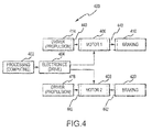
- a lever, pedal, dial, switch, or other command input device may be used to command taxiing, including information such as desired taxi speed.
- Processor 402 may receive one or more commands from a cockpit instrument and provide output in accordance with the same.
- Processor 402 may also perform logic to verify the appropriateness of the received command. For example, a processor may receive a command for taxiing during landing (landing is known to occur through indicators such as weight on wheels, high wheel speed, and high concurrent braking command, among others). Processor 402 may thus determine that the command for taxiing is an error (e.g., human error or electrical error) and ignore the command.
- Processor 402 may be similar to drive electronics controller 102 described in FIG. 1 .
- Processor 402 commands electronic drive 404.
- Electronic drive 404 receives commands from processor 402 and produces drive signals for motors 406 and 408 in response to and in accordance with the command signals. It is contemplated that electronic drive 404 may drive one or more motors. In various embodiments, four motors may be coupled to each aircraft wheel, though in various embodiments at least three to six motors are used. Drive 404 may be similar to drive electronics controller 102 described in FIG. 1 .
- Motors 406 and 408 receive the drive signals from electronic drive 404 and cause motors 406 and 408 to turn in response to the drive signals.
- motors 406 and 408 may be brushless DC motors though the use of any electric motor is contemplated herein.
- Motor 406 provides a mechanical torque input into driver transmission 414 and brake transmission 416.
- Motor 408 provides a mechanical torque input into driver transmission 418 and brake transmission 420.
- Transmissions 414, 416, 418, and 420 may comprise high gear ratio transmissions having gear ratios of, for example, in the range of 40:1 to 80:1.
- the first clutch 440 couples motor 406 with brake transmission 416.
- the first clutch 440 operates to selectively engage motor 406 with brake transmission 416. Such engagement may be in response to commands from processor 402 or other aircraft components.
- Brake transmission 416 may be coupled to a ballscrew that is coupled to a ram. Rotational input from brake transmission 416 is converted to linear force by the ballscrew, which in turn exerts force upon a brake disk stack through the ram.
- Brake transmission 416, the ballscrew, and the ram may comprise a brake clamping system.
- a second clutch 442 may couple motor 408 with driver transmission 418.
- the second clutch 442 may operate to selectively engage motor 408 with driver transmission 418. Such engagement may be in response to commands from processor 402 or other aircraft components.
- Driver transmission 418 is engaged to the same aircraft wheel as driver transmission 414 via a mating portion of the aircraft wheel.
- the second clutch 442 may couple motor 408 with brake transmission 420.
- the second clutch 442 may operate to selectively engage motor 408 with brake transmission 420. Such engagement may be in response to commands from processor 402 or other aircraft components.
- Brake transmission 420 may be coupled to a ballscrew that is coupled to a ram. Rotational input from brake transmission 420 is converted to linear force by the ballscrew, which in turn exerts force upon the brake disk stack through the ram. Both brake transmission 420 and brake transmission 416 exert force (through, for example a ballscrew), on the same brake disk stack.
- Brake transmission 420, the ballscrew, and the ram may comprise a brake clamping system.
- Braking and taxiing system 500 installed on a wheel is shown, according to various embodiments.
- Braking and taxiing system 500 may include a plurality of driver transmissions, such as driver transmission 110, engaged with wheel ring gear 114 of aircraft wheel 116.
- driver transmission 110 may be coupled to wheel ring gear 114 via meshing gears. In such position, an electric motor may provide a motive force to effect taxiing.
- a tire 562 may be coupled to aircraft wheel 116.
- method 600 for actuating a braking and taxiing system may include sending a driver signal to a brake and taxi system in step 601.
- Step 602 may include selectively engaging at least one of a first position, a second position, and a third position.
- step 601 may include sending the driver signal produced by electronic drive 404 to braking and taxiing system 100, the braking and taxiing system 100 comprising clutch 118, motor 104, driver transmission 110, and brake transmission 120.
- motor 104 may be in concentric alignment with driver transmission 110 and in concentric alignment with brake transmission 120.
- Step 602 may include selectively engaging, by clutch 118, at least one of a first position, a second position, and a third position in response to the driver signal.
- Second output shaft 108 of electric motor 104 may be coupled to brake transmission 120 via clutch 118 in response to engagement with the first position.
- First output shaft 106 of electric motor 104 may be engaged with driver transmission 110 via the clutch 118 in response to engagement with the second position.
- First output shaft 106 and second output shaft 108 may not be mechanically coupled to any other component in response to engagement with the third position.
- a pilot may cease to command further taxiing, but not command braking. Accordingly, the pilot intends to allow the aircraft to "coast.”
- the electric motor remains mechanically engaged with aircraft wheel.
- the reflected inertia of the electric motor provides a braking effect on the aircraft wheel.
- the electric motor may disengage from the aircraft wheel, for example, by shifting into a neutral position.
- aircraft wheel is allowed to rotate without the reflected inertia of the electric motor, and thus allowing the aircraft wheel to coast without the braking force provided by the electric motor.
- Transmissions disclosed herein may internally comprise one or more clutches. Moreover, transmissions disclosed herein may comprise the ability to variably adjust the final gear ratio. Such adjustment may be accomplished using any suitable configuration. For example, internal clutches may be used to select different gears internally to affect final gear ratio. Further, continuously variable mechanisms may be used to change final gear ratio.
- a propulsion transmission may have two variable gear ratios. The first variable gear ratio of a propulsion transmission may be a "low" gear intended to bring an aircraft from a stopped position into motion. The second variable gear ratio of a propulsion transmission may be a "high" gear intended to maintain the aircraft within a particular speed range. However, in various embodiments, a continuously variable propulsion transmission may be used.
- Variable adjustment of final gear ratio may be controlled electronically and/or mechanically and/or hydraulically.
- the aforementioned features may be included in any transmission disclosed herein to tune final gear ratio, input/output torque and input/output rotational velocity. While the transmissions disclosed herein may be primarily comprised of gears, the transmissions contemplated herein may include one or more other modes of torque transmission such as belts, chains, levers, pulleys, and the like.
- a clutch may be engaged or disengaged based upon input from one or more gear tooth sensors or the like.
- a gear tooth sensor may sense the position of a gear tooth, for example, using a Hall Effect type sensor.
- the gear tooth position information may be sent to the brake control unit for processing.
- the clutch may be engaged to mate the two gears together. In this regard, a smooth shift is accomplished.
- any gear contemplated herein may have an associated gear tooth sensor which may facilitate the engagement and disengagement of a clutch that selectively couples two or more gears.
- references to "various embodiments”, “one embodiment”, “an embodiment”, “an example embodiment”, etc. indicate that the embodiment described may include a particular feature, structure, or characteristic, but every embodiment may not necessarily include the particular feature, structure, or characteristic. Moreover, such phrases are not necessarily referring to the same embodiment. Further, when a particular feature, structure, or characteristic is described in connection with an embodiment, it is submitted that it is within the knowledge of one skilled in the art to affect such feature, structure, or characteristic in connection with other embodiments whether or not explicitly described. After reading the description, it will be apparent to one skilled in the relevant art(s) how to implement the disclosure in alternative embodiments.
Landscapes
- Engineering & Computer Science (AREA)
- Mechanical Engineering (AREA)
- Aviation & Aerospace Engineering (AREA)
- Transportation (AREA)
- Braking Arrangements (AREA)
Applications Claiming Priority (1)
| Application Number | Priority Date | Filing Date | Title |
|---|---|---|---|
| US14/803,658 US9815551B2 (en) | 2015-07-20 | 2015-07-20 | Systems and methods for aircraft braking and taxiing |
Publications (2)
| Publication Number | Publication Date |
|---|---|
| EP3121077A1 true EP3121077A1 (fr) | 2017-01-25 |
| EP3121077B1 EP3121077B1 (fr) | 2021-02-24 |
Family
ID=56550064
Family Applications (1)
| Application Number | Title | Priority Date | Filing Date |
|---|---|---|---|
| EP16180414.1A Active EP3121077B1 (fr) | 2015-07-20 | 2016-07-20 | Systèmes et procédés de freinage et de roulage d'aéronef |
Country Status (2)
| Country | Link |
|---|---|
| US (1) | US9815551B2 (fr) |
| EP (1) | EP3121077B1 (fr) |
Cited By (3)
| Publication number | Priority date | Publication date | Assignee | Title |
|---|---|---|---|---|
| FR3072924A1 (fr) * | 2017-10-30 | 2019-05-03 | Safran Landing Systems | Equipement electrique destine a etre relie a un actionneur electromecanique de freinage et a un actionneur electromecanique d'entrainement |
| WO2022006662A1 (fr) * | 2020-07-10 | 2022-01-13 | Safran Landing Systems Canada Inc. | Ensemble frein à capacités d'entraînement pour train d'atterrissage |
| WO2025114472A1 (fr) | 2023-12-01 | 2025-06-05 | eMoSys GmbH | Train de roulement d'un aéronef ou d'un véhicule terrestre |
Families Citing this family (5)
| Publication number | Priority date | Publication date | Assignee | Title |
|---|---|---|---|---|
| US10106139B2 (en) * | 2017-02-02 | 2018-10-23 | Goodrich Corporation | Brake systems and methods |
| US10654695B1 (en) * | 2018-11-21 | 2020-05-19 | Goodrich Corporation | Clutch assembly for detecting and measuring slip using proximity sensors |
| US10947094B2 (en) * | 2019-08-05 | 2021-03-16 | Goodrich Corporation | Auxiliary brake assembly |
| US11603188B2 (en) * | 2020-05-06 | 2023-03-14 | Safran Landing Systems Canada Inc. | Autonomous electric taxiing wheel with electrically actuated brake |
| US12162456B2 (en) * | 2021-11-19 | 2024-12-10 | Goodrich Corporation | Feel adjustment braking systems and methods |
Citations (5)
| Publication number | Priority date | Publication date | Assignee | Title |
|---|---|---|---|---|
| US20060065779A1 (en) * | 2004-09-28 | 2006-03-30 | The Boeing Company | Powered nose aircraft wheel system |
| US20070284939A1 (en) * | 2006-06-12 | 2007-12-13 | Honeywell International | Aircraft electric brake and generator therefor |
| WO2009125213A2 (fr) * | 2008-04-11 | 2009-10-15 | Airbus Uk Limited | Dispositif de train d'atterrissage d'avion et ensemble train d'atterrissage avant |
| EP2236419A2 (fr) * | 2009-04-01 | 2010-10-06 | Rolls-Royce plc | Appareil pour circulation au sol d'un avion |
| US20130292992A1 (en) * | 2012-05-03 | 2013-11-07 | Goodrich Corporation | Systems and methods for aircraft braking and taxiing |
Family Cites Families (6)
| Publication number | Priority date | Publication date | Assignee | Title |
|---|---|---|---|---|
| FR2954752B1 (fr) * | 2009-12-24 | 2012-03-09 | Messier Bugatti | Ensemble de roue et frein pour aeronef equipe d'un dispositif d'entrainement en rotation. |
| US9815438B2 (en) | 2010-02-12 | 2017-11-14 | Honeywell International Inc. | Aircraft electric brake actuator assembly with line replaceable actuator brake |
| FR2968274B1 (fr) | 2010-12-06 | 2013-02-01 | Messier Bugatti | Dispositif de freinage/entrainement d'une roue d'aeronef. |
| US9073530B2 (en) * | 2012-05-15 | 2015-07-07 | Goodrich Corporation | Systems and methods for reflected inertia parking brake |
| US9016134B2 (en) * | 2012-12-11 | 2015-04-28 | Goodrich Corporation | Circular load cell strain sensor configuration |
| US9290264B2 (en) | 2013-05-13 | 2016-03-22 | Honeywell International Inc. | Aircraft selectively engageable electric taxi system |
-
2015
- 2015-07-20 US US14/803,658 patent/US9815551B2/en active Active
-
2016
- 2016-07-20 EP EP16180414.1A patent/EP3121077B1/fr active Active
Patent Citations (5)
| Publication number | Priority date | Publication date | Assignee | Title |
|---|---|---|---|---|
| US20060065779A1 (en) * | 2004-09-28 | 2006-03-30 | The Boeing Company | Powered nose aircraft wheel system |
| US20070284939A1 (en) * | 2006-06-12 | 2007-12-13 | Honeywell International | Aircraft electric brake and generator therefor |
| WO2009125213A2 (fr) * | 2008-04-11 | 2009-10-15 | Airbus Uk Limited | Dispositif de train d'atterrissage d'avion et ensemble train d'atterrissage avant |
| EP2236419A2 (fr) * | 2009-04-01 | 2010-10-06 | Rolls-Royce plc | Appareil pour circulation au sol d'un avion |
| US20130292992A1 (en) * | 2012-05-03 | 2013-11-07 | Goodrich Corporation | Systems and methods for aircraft braking and taxiing |
Cited By (6)
| Publication number | Priority date | Publication date | Assignee | Title |
|---|---|---|---|---|
| FR3072924A1 (fr) * | 2017-10-30 | 2019-05-03 | Safran Landing Systems | Equipement electrique destine a etre relie a un actionneur electromecanique de freinage et a un actionneur electromecanique d'entrainement |
| EP3476677A3 (fr) * | 2017-10-30 | 2019-05-08 | Safran Landing Systems | Equipement electrique destine a etre relie a un actionneur electromecanique de freinage et a un actionneur electromecanique d'entrainement |
| US11608039B2 (en) | 2017-10-30 | 2023-03-21 | Safran Landing Systems | Piece of electrical equipment for connecting to an electromechanical brake actuator and to an electromechanical drive actuator |
| WO2022006662A1 (fr) * | 2020-07-10 | 2022-01-13 | Safran Landing Systems Canada Inc. | Ensemble frein à capacités d'entraînement pour train d'atterrissage |
| US11498664B2 (en) | 2020-07-10 | 2022-11-15 | Safran Landing Systems Canada Inc. | Brake assembly with drive capabilities for landing gear |
| WO2025114472A1 (fr) | 2023-12-01 | 2025-06-05 | eMoSys GmbH | Train de roulement d'un aéronef ou d'un véhicule terrestre |
Also Published As
| Publication number | Publication date |
|---|---|
| US9815551B2 (en) | 2017-11-14 |
| EP3121077B1 (fr) | 2021-02-24 |
| US20170021920A1 (en) | 2017-01-26 |
Similar Documents
| Publication | Publication Date | Title |
|---|---|---|
| EP3121077B1 (fr) | Systèmes et procédés de freinage et de roulage d'aéronef | |
| US9017219B2 (en) | Systems and methods for aircraft braking and taxiing | |
| EP3385106B1 (fr) | Ensemble d'essieu comportant plusieurs collets d'embrayage | |
| KR20160018414A (ko) | 랜딩 기어 구동 시스템 | |
| AU2005326186A1 (en) | Aircraft drive | |
| US11866910B2 (en) | Work vehicle multi-speed drive assembly with output control clutch | |
| EP3781476B1 (fr) | Système pour une aile d'aéronef | |
| EP3974266A1 (fr) | Système de freinage hybride | |
| EP2664507B1 (fr) | Systèmes et procédé pour frein de stationnement d'inertie réfléchie | |
| US11639160B2 (en) | Electrical power connection in an emergency park brake system | |
| US20180162331A1 (en) | Systems and methods for aircraft emergency and park brakes | |
| EP2865851A1 (fr) | Système d'actionnement à inverseur de poussée hybride entraîné par un moteur hydraulique rotatif avec amortissement de fin de course | |
| EP0515650A4 (en) | Marine reverse reduction gearbox | |
| EP4146536B1 (fr) | Roue électrique de roulement au sol autonome dotée d'un frein à actionnement électrique | |
| CN102454768A (zh) | 发动机和手动变速器之间的扭矩传递的控制 | |
| EP3392140B1 (fr) | Système de frein de stationnement d'urgence | |
| US10828976B2 (en) | Method of controlling a coupling arrangement in a gearbox | |
| EP4008593B1 (fr) | Systèmes et procédés de surveillance de santé pour servovalves | |
| EP2951065B1 (fr) | Freinage d'un transmission, transmission avec un tel freinage, vehicule avec un tel transmission et procede de commencement (un promenade en voiture) | |
| US12013028B2 (en) | Transmission system for work machine | |
| EP3357771A1 (fr) | Procédé et système de freinage | |
| EP4575263A1 (fr) | Double trajet de charge pour un actionneur | |
| US20050202928A1 (en) | Method and apparatus for providing momentary torque reversal for a transmission having an automated shift system | |
| CA3252801A1 (en) | Dual load path actuator | |
| JPH0710031A (ja) | 装軌式車両のギヤード操向装置、およびその制御装置 |
Legal Events
| Date | Code | Title | Description |
|---|---|---|---|
| PUAI | Public reference made under article 153(3) epc to a published international application that has entered the european phase |
Free format text: ORIGINAL CODE: 0009012 |
|
| STAA | Information on the status of an ep patent application or granted ep patent |
Free format text: STATUS: THE APPLICATION HAS BEEN PUBLISHED |
|
| AK | Designated contracting states |
Kind code of ref document: A1 Designated state(s): AL AT BE BG CH CY CZ DE DK EE ES FI FR GB GR HR HU IE IS IT LI LT LU LV MC MK MT NL NO PL PT RO RS SE SI SK SM TR |
|
| AX | Request for extension of the european patent |
Extension state: BA ME |
|
| RIN1 | Information on inventor provided before grant (corrected) |
Inventor name: REHFUS, KEVIN Inventor name: DRENNEN, DAVID |
|
| STAA | Information on the status of an ep patent application or granted ep patent |
Free format text: STATUS: REQUEST FOR EXAMINATION WAS MADE |
|
| 17P | Request for examination filed |
Effective date: 20170725 |
|
| RBV | Designated contracting states (corrected) |
Designated state(s): AL AT BE BG CH CY CZ DE DK EE ES FI FR GB GR HR HU IE IS IT LI LT LU LV MC MK MT NL NO PL PT RO RS SE SI SK SM TR |
|
| GRAP | Despatch of communication of intention to grant a patent |
Free format text: ORIGINAL CODE: EPIDOSNIGR1 |
|
| STAA | Information on the status of an ep patent application or granted ep patent |
Free format text: STATUS: GRANT OF PATENT IS INTENDED |
|
| INTG | Intention to grant announced |
Effective date: 20200915 |
|
| GRAS | Grant fee paid |
Free format text: ORIGINAL CODE: EPIDOSNIGR3 |
|
| GRAA | (expected) grant |
Free format text: ORIGINAL CODE: 0009210 |
|
| STAA | Information on the status of an ep patent application or granted ep patent |
Free format text: STATUS: THE PATENT HAS BEEN GRANTED |
|
| AK | Designated contracting states |
Kind code of ref document: B1 Designated state(s): AL AT BE BG CH CY CZ DE DK EE ES FI FR GB GR HR HU IE IS IT LI LT LU LV MC MK MT NL NO PL PT RO RS SE SI SK SM TR |
|
| REG | Reference to a national code |
Ref country code: CH Ref legal event code: EP |
|
| REG | Reference to a national code |
Ref country code: DE Ref legal event code: R096 Ref document number: 602016052987 Country of ref document: DE |
|
| REG | Reference to a national code |
Ref country code: AT Ref legal event code: REF Ref document number: 1364058 Country of ref document: AT Kind code of ref document: T Effective date: 20210315 |
|
| REG | Reference to a national code |
Ref country code: IE Ref legal event code: FG4D |
|
| REG | Reference to a national code |
Ref country code: LT Ref legal event code: MG9D |
|
| REG | Reference to a national code |
Ref country code: NL Ref legal event code: MP Effective date: 20210224 |
|
| PG25 | Lapsed in a contracting state [announced via postgrant information from national office to epo] |
Ref country code: NO Free format text: LAPSE BECAUSE OF FAILURE TO SUBMIT A TRANSLATION OF THE DESCRIPTION OR TO PAY THE FEE WITHIN THE PRESCRIBED TIME-LIMIT Effective date: 20210524 Ref country code: PT Free format text: LAPSE BECAUSE OF FAILURE TO SUBMIT A TRANSLATION OF THE DESCRIPTION OR TO PAY THE FEE WITHIN THE PRESCRIBED TIME-LIMIT Effective date: 20210624 Ref country code: BG Free format text: LAPSE BECAUSE OF FAILURE TO SUBMIT A TRANSLATION OF THE DESCRIPTION OR TO PAY THE FEE WITHIN THE PRESCRIBED TIME-LIMIT Effective date: 20210524 Ref country code: GR Free format text: LAPSE BECAUSE OF FAILURE TO SUBMIT A TRANSLATION OF THE DESCRIPTION OR TO PAY THE FEE WITHIN THE PRESCRIBED TIME-LIMIT Effective date: 20210525 Ref country code: FI Free format text: LAPSE BECAUSE OF FAILURE TO SUBMIT A TRANSLATION OF THE DESCRIPTION OR TO PAY THE FEE WITHIN THE PRESCRIBED TIME-LIMIT Effective date: 20210224 Ref country code: HR Free format text: LAPSE BECAUSE OF FAILURE TO SUBMIT A TRANSLATION OF THE DESCRIPTION OR TO PAY THE FEE WITHIN THE PRESCRIBED TIME-LIMIT Effective date: 20210224 Ref country code: LT Free format text: LAPSE BECAUSE OF FAILURE TO SUBMIT A TRANSLATION OF THE DESCRIPTION OR TO PAY THE FEE WITHIN THE PRESCRIBED TIME-LIMIT Effective date: 20210224 |
|
| REG | Reference to a national code |
Ref country code: AT Ref legal event code: MK05 Ref document number: 1364058 Country of ref document: AT Kind code of ref document: T Effective date: 20210224 |
|
| PG25 | Lapsed in a contracting state [announced via postgrant information from national office to epo] |
Ref country code: RS Free format text: LAPSE BECAUSE OF FAILURE TO SUBMIT A TRANSLATION OF THE DESCRIPTION OR TO PAY THE FEE WITHIN THE PRESCRIBED TIME-LIMIT Effective date: 20210224 Ref country code: PL Free format text: LAPSE BECAUSE OF FAILURE TO SUBMIT A TRANSLATION OF THE DESCRIPTION OR TO PAY THE FEE WITHIN THE PRESCRIBED TIME-LIMIT Effective date: 20210224 Ref country code: LV Free format text: LAPSE BECAUSE OF FAILURE TO SUBMIT A TRANSLATION OF THE DESCRIPTION OR TO PAY THE FEE WITHIN THE PRESCRIBED TIME-LIMIT Effective date: 20210224 Ref country code: NL Free format text: LAPSE BECAUSE OF FAILURE TO SUBMIT A TRANSLATION OF THE DESCRIPTION OR TO PAY THE FEE WITHIN THE PRESCRIBED TIME-LIMIT Effective date: 20210224 Ref country code: SE Free format text: LAPSE BECAUSE OF FAILURE TO SUBMIT A TRANSLATION OF THE DESCRIPTION OR TO PAY THE FEE WITHIN THE PRESCRIBED TIME-LIMIT Effective date: 20210224 |
|
| PG25 | Lapsed in a contracting state [announced via postgrant information from national office to epo] |
Ref country code: IS Free format text: LAPSE BECAUSE OF FAILURE TO SUBMIT A TRANSLATION OF THE DESCRIPTION OR TO PAY THE FEE WITHIN THE PRESCRIBED TIME-LIMIT Effective date: 20210624 |
|
| PG25 | Lapsed in a contracting state [announced via postgrant information from national office to epo] |
Ref country code: SM Free format text: LAPSE BECAUSE OF FAILURE TO SUBMIT A TRANSLATION OF THE DESCRIPTION OR TO PAY THE FEE WITHIN THE PRESCRIBED TIME-LIMIT Effective date: 20210224 Ref country code: AT Free format text: LAPSE BECAUSE OF FAILURE TO SUBMIT A TRANSLATION OF THE DESCRIPTION OR TO PAY THE FEE WITHIN THE PRESCRIBED TIME-LIMIT Effective date: 20210224 Ref country code: CZ Free format text: LAPSE BECAUSE OF FAILURE TO SUBMIT A TRANSLATION OF THE DESCRIPTION OR TO PAY THE FEE WITHIN THE PRESCRIBED TIME-LIMIT Effective date: 20210224 Ref country code: EE Free format text: LAPSE BECAUSE OF FAILURE TO SUBMIT A TRANSLATION OF THE DESCRIPTION OR TO PAY THE FEE WITHIN THE PRESCRIBED TIME-LIMIT Effective date: 20210224 |
|
| REG | Reference to a national code |
Ref country code: DE Ref legal event code: R097 Ref document number: 602016052987 Country of ref document: DE |
|
| PG25 | Lapsed in a contracting state [announced via postgrant information from national office to epo] |
Ref country code: DK Free format text: LAPSE BECAUSE OF FAILURE TO SUBMIT A TRANSLATION OF THE DESCRIPTION OR TO PAY THE FEE WITHIN THE PRESCRIBED TIME-LIMIT Effective date: 20210224 Ref country code: ES Free format text: LAPSE BECAUSE OF FAILURE TO SUBMIT A TRANSLATION OF THE DESCRIPTION OR TO PAY THE FEE WITHIN THE PRESCRIBED TIME-LIMIT Effective date: 20210224 Ref country code: SK Free format text: LAPSE BECAUSE OF FAILURE TO SUBMIT A TRANSLATION OF THE DESCRIPTION OR TO PAY THE FEE WITHIN THE PRESCRIBED TIME-LIMIT Effective date: 20210224 Ref country code: RO Free format text: LAPSE BECAUSE OF FAILURE TO SUBMIT A TRANSLATION OF THE DESCRIPTION OR TO PAY THE FEE WITHIN THE PRESCRIBED TIME-LIMIT Effective date: 20210224 |
|
| PLBE | No opposition filed within time limit |
Free format text: ORIGINAL CODE: 0009261 |
|
| STAA | Information on the status of an ep patent application or granted ep patent |
Free format text: STATUS: NO OPPOSITION FILED WITHIN TIME LIMIT |
|
| PG25 | Lapsed in a contracting state [announced via postgrant information from national office to epo] |
Ref country code: AL Free format text: LAPSE BECAUSE OF FAILURE TO SUBMIT A TRANSLATION OF THE DESCRIPTION OR TO PAY THE FEE WITHIN THE PRESCRIBED TIME-LIMIT Effective date: 20210224 |
|
| REG | Reference to a national code |
Ref country code: DE Ref legal event code: R119 Ref document number: 602016052987 Country of ref document: DE |
|
| 26N | No opposition filed |
Effective date: 20211125 |
|
| PG25 | Lapsed in a contracting state [announced via postgrant information from national office to epo] |
Ref country code: SI Free format text: LAPSE BECAUSE OF FAILURE TO SUBMIT A TRANSLATION OF THE DESCRIPTION OR TO PAY THE FEE WITHIN THE PRESCRIBED TIME-LIMIT Effective date: 20210224 |
|
| REG | Reference to a national code |
Ref country code: CH Ref legal event code: PL |
|
| PG25 | Lapsed in a contracting state [announced via postgrant information from national office to epo] |
Ref country code: MC Free format text: LAPSE BECAUSE OF FAILURE TO SUBMIT A TRANSLATION OF THE DESCRIPTION OR TO PAY THE FEE WITHIN THE PRESCRIBED TIME-LIMIT Effective date: 20210224 |
|
| REG | Reference to a national code |
Ref country code: BE Ref legal event code: MM Effective date: 20210731 |
|
| PG25 | Lapsed in a contracting state [announced via postgrant information from national office to epo] |
Ref country code: LI Free format text: LAPSE BECAUSE OF NON-PAYMENT OF DUE FEES Effective date: 20210731 Ref country code: IT Free format text: LAPSE BECAUSE OF FAILURE TO SUBMIT A TRANSLATION OF THE DESCRIPTION OR TO PAY THE FEE WITHIN THE PRESCRIBED TIME-LIMIT Effective date: 20210224 Ref country code: DE Free format text: LAPSE BECAUSE OF NON-PAYMENT OF DUE FEES Effective date: 20220201 Ref country code: CH Free format text: LAPSE BECAUSE OF NON-PAYMENT OF DUE FEES Effective date: 20210731 |
|
| PG25 | Lapsed in a contracting state [announced via postgrant information from national office to epo] |
Ref country code: IS Free format text: LAPSE BECAUSE OF FAILURE TO SUBMIT A TRANSLATION OF THE DESCRIPTION OR TO PAY THE FEE WITHIN THE PRESCRIBED TIME-LIMIT Effective date: 20210624 Ref country code: LU Free format text: LAPSE BECAUSE OF NON-PAYMENT OF DUE FEES Effective date: 20210720 |
|
| PG25 | Lapsed in a contracting state [announced via postgrant information from national office to epo] |
Ref country code: IE Free format text: LAPSE BECAUSE OF NON-PAYMENT OF DUE FEES Effective date: 20210720 Ref country code: BE Free format text: LAPSE BECAUSE OF NON-PAYMENT OF DUE FEES Effective date: 20210731 |
|
| PG25 | Lapsed in a contracting state [announced via postgrant information from national office to epo] |
Ref country code: HU Free format text: LAPSE BECAUSE OF FAILURE TO SUBMIT A TRANSLATION OF THE DESCRIPTION OR TO PAY THE FEE WITHIN THE PRESCRIBED TIME-LIMIT; INVALID AB INITIO Effective date: 20160720 |
|
| P01 | Opt-out of the competence of the unified patent court (upc) registered |
Effective date: 20230522 |
|
| PG25 | Lapsed in a contracting state [announced via postgrant information from national office to epo] |
Ref country code: CY Free format text: LAPSE BECAUSE OF FAILURE TO SUBMIT A TRANSLATION OF THE DESCRIPTION OR TO PAY THE FEE WITHIN THE PRESCRIBED TIME-LIMIT Effective date: 20210224 |
|
| PG25 | Lapsed in a contracting state [announced via postgrant information from national office to epo] |
Ref country code: MK Free format text: LAPSE BECAUSE OF FAILURE TO SUBMIT A TRANSLATION OF THE DESCRIPTION OR TO PAY THE FEE WITHIN THE PRESCRIBED TIME-LIMIT Effective date: 20210224 |
|
| PG25 | Lapsed in a contracting state [announced via postgrant information from national office to epo] |
Ref country code: MT Free format text: LAPSE BECAUSE OF FAILURE TO SUBMIT A TRANSLATION OF THE DESCRIPTION OR TO PAY THE FEE WITHIN THE PRESCRIBED TIME-LIMIT Effective date: 20210224 |
|
| PGFP | Annual fee paid to national office [announced via postgrant information from national office to epo] |
Ref country code: GB Payment date: 20250619 Year of fee payment: 10 |
|
| PGFP | Annual fee paid to national office [announced via postgrant information from national office to epo] |
Ref country code: FR Payment date: 20250620 Year of fee payment: 10 |
|
| PG25 | Lapsed in a contracting state [announced via postgrant information from national office to epo] |
Ref country code: TR Free format text: LAPSE BECAUSE OF FAILURE TO SUBMIT A TRANSLATION OF THE DESCRIPTION OR TO PAY THE FEE WITHIN THE PRESCRIBED TIME-LIMIT Effective date: 20210224 |