EP3121425A1 - Verfahren und vorrichtung zur untersuchung einer elektronisch gesteuerten einspritzvorrichtung zum einspritzen eines kraftstoffs in einen zylinder eines verbrennungsmotors - Google Patents
Verfahren und vorrichtung zur untersuchung einer elektronisch gesteuerten einspritzvorrichtung zum einspritzen eines kraftstoffs in einen zylinder eines verbrennungsmotors Download PDFInfo
- Publication number
- EP3121425A1 EP3121425A1 EP16174950.2A EP16174950A EP3121425A1 EP 3121425 A1 EP3121425 A1 EP 3121425A1 EP 16174950 A EP16174950 A EP 16174950A EP 3121425 A1 EP3121425 A1 EP 3121425A1
- Authority
- EP
- European Patent Office
- Prior art keywords
- fuel
- injection
- test
- cylinder
- engine
- Prior art date
- Legal status (The legal status is an assumption and is not a legal conclusion. Google has not performed a legal analysis and makes no representation as to the accuracy of the status listed.)
- Withdrawn
Links
Images

Classifications
-
- F—MECHANICAL ENGINEERING; LIGHTING; HEATING; WEAPONS; BLASTING
- F02—COMBUSTION ENGINES; HOT-GAS OR COMBUSTION-PRODUCT ENGINE PLANTS
- F02D—CONTROLLING COMBUSTION ENGINES
- F02D41/00—Electrical control of supply of combustible mixture or its constituents
- F02D41/22—Safety or indicating devices for abnormal conditions
-
- F—MECHANICAL ENGINEERING; LIGHTING; HEATING; WEAPONS; BLASTING
- F02—COMBUSTION ENGINES; HOT-GAS OR COMBUSTION-PRODUCT ENGINE PLANTS
- F02D—CONTROLLING COMBUSTION ENGINES
- F02D41/00—Electrical control of supply of combustible mixture or its constituents
- F02D41/30—Controlling fuel injection
- F02D41/38—Controlling fuel injection of the high pressure type
- F02D41/40—Controlling fuel injection of the high pressure type with means for controlling injection timing or duration
- F02D41/402—Multiple injections
- F02D41/405—Multiple injections with post injections
-
- F—MECHANICAL ENGINEERING; LIGHTING; HEATING; WEAPONS; BLASTING
- F02—COMBUSTION ENGINES; HOT-GAS OR COMBUSTION-PRODUCT ENGINE PLANTS
- F02D—CONTROLLING COMBUSTION ENGINES
- F02D19/00—Controlling engines characterised by their use of non-liquid fuels, pluralities of fuels, or non-fuel substances added to the combustible mixtures
- F02D19/06—Controlling engines characterised by their use of non-liquid fuels, pluralities of fuels, or non-fuel substances added to the combustible mixtures peculiar to engines working with pluralities of fuels, e.g. alternatively with light and heavy fuel oil, other than engines indifferent to the fuel consumed
- F02D19/0623—Failure diagnosis or prevention; Safety measures; Testing
-
- F—MECHANICAL ENGINEERING; LIGHTING; HEATING; WEAPONS; BLASTING
- F02—COMBUSTION ENGINES; HOT-GAS OR COMBUSTION-PRODUCT ENGINE PLANTS
- F02D—CONTROLLING COMBUSTION ENGINES
- F02D19/00—Controlling engines characterised by their use of non-liquid fuels, pluralities of fuels, or non-fuel substances added to the combustible mixtures
- F02D19/06—Controlling engines characterised by their use of non-liquid fuels, pluralities of fuels, or non-fuel substances added to the combustible mixtures peculiar to engines working with pluralities of fuels, e.g. alternatively with light and heavy fuel oil, other than engines indifferent to the fuel consumed
- F02D19/0639—Controlling engines characterised by their use of non-liquid fuels, pluralities of fuels, or non-fuel substances added to the combustible mixtures peculiar to engines working with pluralities of fuels, e.g. alternatively with light and heavy fuel oil, other than engines indifferent to the fuel consumed characterised by the type of fuels
- F02D19/0642—Controlling engines characterised by their use of non-liquid fuels, pluralities of fuels, or non-fuel substances added to the combustible mixtures peculiar to engines working with pluralities of fuels, e.g. alternatively with light and heavy fuel oil, other than engines indifferent to the fuel consumed characterised by the type of fuels at least one fuel being gaseous, the other fuels being gaseous or liquid at standard conditions
-
- F—MECHANICAL ENGINEERING; LIGHTING; HEATING; WEAPONS; BLASTING
- F02—COMBUSTION ENGINES; HOT-GAS OR COMBUSTION-PRODUCT ENGINE PLANTS
- F02D—CONTROLLING COMBUSTION ENGINES
- F02D41/00—Electrical control of supply of combustible mixture or its constituents
- F02D41/0025—Controlling engines characterised by use of non-liquid fuels, pluralities of fuels, or non-fuel substances added to the combustible mixtures
-
- F—MECHANICAL ENGINEERING; LIGHTING; HEATING; WEAPONS; BLASTING
- F02—COMBUSTION ENGINES; HOT-GAS OR COMBUSTION-PRODUCT ENGINE PLANTS
- F02D—CONTROLLING COMBUSTION ENGINES
- F02D41/00—Electrical control of supply of combustible mixture or its constituents
- F02D41/22—Safety or indicating devices for abnormal conditions
- F02D41/221—Safety or indicating devices for abnormal conditions relating to the failure of actuators or electrically driven elements
-
- F—MECHANICAL ENGINEERING; LIGHTING; HEATING; WEAPONS; BLASTING
- F02—COMBUSTION ENGINES; HOT-GAS OR COMBUSTION-PRODUCT ENGINE PLANTS
- F02D—CONTROLLING COMBUSTION ENGINES
- F02D41/00—Electrical control of supply of combustible mixture or its constituents
- F02D41/30—Controlling fuel injection
- F02D41/38—Controlling fuel injection of the high pressure type
- F02D41/40—Controlling fuel injection of the high pressure type with means for controlling injection timing or duration
-
- F—MECHANICAL ENGINEERING; LIGHTING; HEATING; WEAPONS; BLASTING
- F02—COMBUSTION ENGINES; HOT-GAS OR COMBUSTION-PRODUCT ENGINE PLANTS
- F02D—CONTROLLING COMBUSTION ENGINES
- F02D41/00—Electrical control of supply of combustible mixture or its constituents
- F02D41/22—Safety or indicating devices for abnormal conditions
- F02D2041/224—Diagnosis of the fuel system
-
- F—MECHANICAL ENGINEERING; LIGHTING; HEATING; WEAPONS; BLASTING
- F02—COMBUSTION ENGINES; HOT-GAS OR COMBUSTION-PRODUCT ENGINE PLANTS
- F02D—CONTROLLING COMBUSTION ENGINES
- F02D2200/00—Input parameters for engine control
- F02D2200/02—Input parameters for engine control the parameters being related to the engine
- F02D2200/06—Fuel or fuel supply system parameters
- F02D2200/0602—Fuel pressure
-
- F—MECHANICAL ENGINEERING; LIGHTING; HEATING; WEAPONS; BLASTING
- F02—COMBUSTION ENGINES; HOT-GAS OR COMBUSTION-PRODUCT ENGINE PLANTS
- F02D—CONTROLLING COMBUSTION ENGINES
- F02D2250/00—Engine control related to specific problems or objectives
- F02D2250/04—Fuel pressure pulsation in common rails
-
- Y—GENERAL TAGGING OF NEW TECHNOLOGICAL DEVELOPMENTS; GENERAL TAGGING OF CROSS-SECTIONAL TECHNOLOGIES SPANNING OVER SEVERAL SECTIONS OF THE IPC; TECHNICAL SUBJECTS COVERED BY FORMER USPC CROSS-REFERENCE ART COLLECTIONS [XRACs] AND DIGESTS
- Y02—TECHNOLOGIES OR APPLICATIONS FOR MITIGATION OR ADAPTATION AGAINST CLIMATE CHANGE
- Y02T—CLIMATE CHANGE MITIGATION TECHNOLOGIES RELATED TO TRANSPORTATION
- Y02T10/00—Road transport of goods or passengers
- Y02T10/10—Internal combustion engine [ICE] based vehicles
- Y02T10/30—Use of alternative fuels, e.g. biofuels
-
- Y—GENERAL TAGGING OF NEW TECHNOLOGICAL DEVELOPMENTS; GENERAL TAGGING OF CROSS-SECTIONAL TECHNOLOGIES SPANNING OVER SEVERAL SECTIONS OF THE IPC; TECHNICAL SUBJECTS COVERED BY FORMER USPC CROSS-REFERENCE ART COLLECTIONS [XRACs] AND DIGESTS
- Y02—TECHNOLOGIES OR APPLICATIONS FOR MITIGATION OR ADAPTATION AGAINST CLIMATE CHANGE
- Y02T—CLIMATE CHANGE MITIGATION TECHNOLOGIES RELATED TO TRANSPORTATION
- Y02T10/00—Road transport of goods or passengers
- Y02T10/10—Internal combustion engine [ICE] based vehicles
- Y02T10/40—Engine management systems
Definitions
- the invention relates to a method for inspecting an electronically controlled injection device for injecting a fuel into a cylinder of an internal combustion engine, in particular a large two-stroke diesel engine, having a piston for reciprocating movement in the cylinder, and a common rail system with a pressure reservoir for delivering fuel to the cylinder. Furthermore, the invention relates to a large diesel engine, especially a large two-stroke diesel engine, having a control device being designed for performing this method.
- large diesel engine or the like encompasses also such large engines, which can be operated beside the diesel operation, that is characterized by the self-ignition of the fuel, also in an Otto operation, that is characterized by an external ignition, or in a mixed form of these two operations.
- Modern large diesel engines are electronically controlled and usually comprise a common rail system with a pressure reservoir for supplying the fuel, e.g. heavy oil, to the cylinders.
- the fuel in the pressure reservoir has a pressure of several hundred bar, for example 700-900 bar, but the pressure may also be higher, even more than 1000 bar.
- each cylinder at least one, but typically two or three electronically controlled injection devices are provided being connected to the pressure reservoir for receiving pressurized fuel from there.
- Each injection device comprises a control unit and an injector.
- the injector has a spring-loaded valve member cooperating with a valve seat as well as a nozzle for injecting the fuel into the combustion chamber of the cylinder.
- the injector is in fluid communication with the pressure reservoir. If the valve member is lifted the pressurized fluid can pass between the valve member and the valve seat and enters the nozzle for being injected. If the valve member is pressed into the valve seat the connection to the nozzle is closed an no fuel can reach the nozzle.
- the control unit of the injection device is also in fluid communication with the pressure reservoir and uses the pressurized fuel as pressure medium for keeping the valve member in a sealing contact with the valve seat.
- the control unit releases the fuel pressure from the valve member the high pressure at the valve seat prevails the spring load and the fuel pressure in the control unit and thus lifts the valve member for initiating the injection of fuel into the combustion chamber.
- the control unit works like a switching valve. In the closed position the fuel pressure together with the spring load is used to keep the valve member in sealing contact with the valve seat and in the opened position the valve member is released from the fuel pressure, so that the higher fuel pressure in the region of the valve seat lifts the valve member from the valve seat.
- the switching between the positions is realized by way of an electromagnetic actuator receiving an electric signal as fuel injection command from the electronic engine control unit.
- an electromagnetic actuator receiving an electric signal as fuel injection command from the electronic engine control unit.
- This method enables the assessment of the condition of an injection device of an internal combustion engine, especially of a large diesel engine, during operation of the machine by measuring the pressure response of the pressure reservoir of the common rail system and analyzing this pressure response to the test injection by comparison with a reference signal. Since the geometry of the pressure reservoir and all other components of the common rail system is known as well as the actual values of the parameters like the pressure in the pressure reservoir, the length of the test injection command, the start of the test injection command it is possible to investigate whether the relationship between the length of the test injection command and the real amount of fuel that is injected into the combustion chamber is still correct. Thus, there is the possibility to assess the condition of the tested injection device during the operation of the engine. By this it is avoidable to exchange an injection device or parts thereof to early, i.e.
- the injection of the test amount of fuel is a post-injection, meaning that the injection of the test amount starts only after the injection of the normal amount of fuel that is used for the operation of the cylinder under normal working conditions.
- the test amount of fuel will at most cause a negligible and temporary rise of the exhaust gas temperature.
- the test injection command is started when the piston has passed the top dead center.
- the working stroke of this piston already started, so that the contribution of the test amount of fuel to the acceleration of the crankshaft is even more reduced.
- the operational fuel command is the normal fuel command that is used for the injection device to perform the normal operation of the combustion engine. Freezing this operational fuel injection command, that is not modifying it during the test cycle, makes the analysis of the comparison of the pressure response with the reference signal easier and even more accurate.
- each cylinder of a large diesel engine may be provided with more than one injection device, it is preferred that a specific injection device is selected from a plurality of injection devices, the test cycle is started for the specific injection device and during the test cycle the operational fuel injection commands for all injection devices are frozen to a constant value.
- the constant value corresponds to the operational fuel injection command that was used just prior to the starting of the test cycle.
- test injection command is timed such that the injected test amount of fuel does not result in an essential rise of the combustion pressure. That is, the beginning of the test injection command to the injector to be tested is selected in such a way, that the injected test amount of fuel does not cause a significant rise of the combustion pressure or a significant contribution to the acceleration of the crank shaft.
- test injection command for the injection device is started less than four milliseconds, preferably less than two milliseconds, after the end of the operational fuel injection command.
- test injection command is longer than each operational fuel injection command under normal operation of the engine.
- pressure response of the pressure reservoir is even more pronounced.
- test injection command when the test injection command is timed such, that the injection of the test amount of fuel is finished before a scavenging air opening of the cylinder supplied by the injection device under test is opened. By this, it can be avoided that fuel enters into the scavenging air system of the combustion engine.
- test cycle comprises at least one repetition of step a) and step b) for the same injection device during consecutive working cycles of the combustion engine. It is also possible, to collect pressure responses for several steps a) and steps b) and to sum them up or analyze a mean value of the pressure responses.
- the combustion engine is running at low load, in particular at most at 50% of its full load, during the test cycle.
- the operational fuel injection commands are typically shorter, thus the relative influence of the test amount of fuel on the pressure response of the pressure reservoir becomes larger. This even enhances the accuracy of inspecting the injection device.
- the reference signal is determined by means of at least one injection device in mint condition having no wear and no tear. Using a new injection device or an injection device having only negligible wear is an easy measure to establish a reliable reference signal.
- the invention proposes a large diesel engine, especially a large two-stroke diesel engine, having at least one cylinder, a common rail system with a pressure reservoir for delivering a fuel to the cylinder, at least one electronically controlled injection device for injecting the fuel into the cylinder, and a control device being designed for performing a method according to the invention.
- a large diesel engine it is possible to inspect the condition of the injection device or the injection devices during normal operation of the engine.
- the control device is preferably included into the engine control unit for the diesel engine and may comprise a software module being adapted to perform a method according to the invention.
- the large diesel engine according to the invention may be designed as a four-stroke engine or as a two-stroke engine, in particular a large two-stroke engine with longitudinal scavenging.
- the large diesel engine according to the invention may be designed as a dual fuel engine for the combustion of a liquid fuel, preferably heavy oil, and for the combustion of a gas.
- Fig. 1 shows in a schematic representation essential parts of a common rail system 2 for the fuel supply of an internal combustion machine, in particular a large diesel engine.
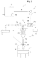
- Fig. 2 is a schematic representation of some components of a large diesel engine being designated in its entity by reference numeral 1.
- the large diesel engine 1 has at least one cylinder 3 but typically more, for example up to fourteen cylinders 3. Since it is sufficient for the understanding of the invention, in Fig. 1 only one cylinder 3 is shown.
- a piston 4 is arranged for a reciprocating movement between a top dead center and a bottom dead center.
- the top side of the piston 4 and a cylinder cover 31 together with the cylindrical wall of the cylinder 3 are limiting a combustion chamber 32 in which the fuel is injected for the combustion.
- the exhaust valve of the cylinder is not shown in the schematic Fig. 2 .
- the invention is not restricted to this specific type of an internal combustion machine.
- the internal combustion engine may be any type of large diesel engine as they are used for example as main propulsion units for ships or also in stationary operation, for example for driving large generators for the production of electrical power.
- the large diesel engine 1 can be designed as two-stroke or four-stroke engine. It is also possible that the large diesel engine 1 is designed as a dual fuel engine for the combustion of a liquid fuel and for the combustion of a gas, for example natural gas.
- the large two-stroke diesel engine 1 is usually operated with heavy oil. The same is true for the operation of a dual fuel engine in the liquid mode.
- a engine control unit 5 operates and controls all functions of the large diesel engine 1, for example the operation of the exhaust valves for the gas exchange and the injection process for the fuel, by way of electronic signals and commands.
- the engine control unit 5 receives information from several detectors, sensors or measuring devices.
- Fig. 1 shows the common rail system 2 of the large diesel engine 1 that supplies the fuel, e.g. heavy oil, to the combustion chamber 32 of the cylinders 3.
- the common rail system in Fig. 1 is designed for the supply of six cylinders 3, however this number is only an example.
- the common rail system 2 comprises a pressure reservoir 6 also called "fuel rail" which contains the fuel to be delivered to the cylinders 3 under a high pressure that essentially corresponds to the injection pressure.
- a pressure reservoir 6 also called "fuel rail” which contains the fuel to be delivered to the cylinders 3 under a high pressure that essentially corresponds to the injection pressure.
- One or more fuel pumps 8 - in this example two fuel pumps 8 - driven by a drive unit 9 supply the pressure reservoir with the fuel under high pressure.
- the pressure of the fuel in the pressure vessel has for example a value of 700-900 bar but may also be higher.
- a fuel booster pump 11 which is connected with a reservoir for the fuel (not shown) delivers the fuel to the fuel pumps 8.
- a closed-loop control For maintaining the pressure of the fuel in the pressure reservoir on a constant value a closed-loop control is provided.
- One or more pressure sensors 61 - in this example two pressure sensors 61 - measure the actual value of the pressure in the pressure reservoir 6. This value is transmitted to the engine control unit 5 as indicated in Fig. 1 by the arrows without reference numeral and compared with the set value for the pressure. Based upon this comparison the engine control unit sends a signal to flow control valves 10 with which the delivery rate of the fuel pumps 8 may be adjusted.
- this closed-loop control the pressure of the fuel in the pressure reservoir is kept on a constant value during operation of the engine 1.
- the pressure reservoir 6 is in fluid communication with a plurality of electronically controlled injection devices 7 for injecting the fuel into the combustion chamber 32 of the respective cylinder 3.
- a plurality of electronically controlled injection devices 7 for injecting the fuel into the combustion chamber 32 of the respective cylinder 3.
- the electronically controlled injection device 7 (see Fig. 2 ) comprises a control unit 71 and an injector 72 mounted to the cylinder cover 31 of the respective cylinder 3.
- the injector 72 comprises a valve member 722 cooperating with a valve seat 721 and a nozzle 724 for injecting the fuel into the combustion chamber 32.
- the valve member is spring loaded by a spring 723 exerting a force that presses the valve member 722 into the valve seat 724.
- the pressurized fuel as indicated by the dashed lines in Fig. 2 , being supplied by the pressure reservoir 6 is fed to the injector 72 at a location upstream of the valve seat 721.
- the injector 72 is fed to the injector 72 at a location upstream of the valve seat 721.
- the control unit 71 of the injector device 7 comprises a control chamber 711 which is in fluid communication with the pressure reservoir 6.
- An inlet throttle 714 is provided in the connection between the pressure chamber 6 and the control chamber 711.
- the control chamber 711 is in fluid communication with a switching device 712 so that the pressurized fuel can flow from the control chamber 711 to the switching unit 712.
- the switching unit 712 has two positions: in the opened position the fuel coming from the control chamber 711 can pass over an outlet throttle 716 through the switching device 712 and is discharged to a drain 13. In the closed position the flow-through to the drain 13 is closed and the fuel coming from the control chamber 711 cannot pass the switching unit 712.
- an electromagnetic actuator 713 is provided for changing from the closed to the opened position.
- the electromagnetic actuator comprises a rod 715 which can be moved by means of an electromagnetic coil between a position where the rod 715 closes the fluid communication to the drain 13 and a position where the rod 715 opens the fluid communication to the drain 13.
- the engine control unit 5 sends an operational fuel injection command OF to the electromagnetic actuator 713 of the injection device 7 (see also Fig. 3 ).
- the operational fuel injection command OF the electromagnetic coil of the electromagnetic actuator 713 pulls the rod 715 into the position where the fluid communication to the drain 13 is opened.
- the pressure of the fuel in the control chamber 711 decreases to a low value.
- the high pressure of the fuel in the region of the valve seat 721 prevails the low pressure in the control chamber 711 and the spring load of the spring 723. Consequently, the valve member 722 is lifted from the valve seat 721. In this state the fuel can pass between the valve seat 721 and the valve member 722 to the nozzle 724 for being injected into the combustion chamber.
- the rod 715 is moved back to the position, in which it closes the fluid communication through the switching unit 712 to the drain 13.
- the pressure in the control chamber 711 increases and together with the spring load of the spring 723 prevails the pressure of the fuel at the valve seat 724.
- the valve member 722 is forced into sealing engagement with the valve seat 721. The injection is finished.
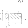
- the beginning of the operational fuel injection command OF i.e. the change from the low level LL to the high level HL determines the crank angle, at which the respective injection into the combustion chamber 32 begins, whereas the time length t1 of the operational fuel injection command OF determines the amount of fuel that is injected during the respective injection.
- a method is proposed which is suited for inspecting the electronically controlled injection devices 7 of the large diesel engine 1 and which renders possible to check the relationship between the time length t1 of the operational fuel injection command OF and the amount of fuel that is really injected into the combustion chamber.
- One of the advantages of the method according to the invention is the fact that it can be performed during the operation of the engine 1. There is no need to stop the engine 1 or to dismount any components from the engine.
- One embodiment of this method is now explained in more detail.
- control device 51 is provided which is designed for performing the method.
- control device 51 is integrated into the engine control unit 5 and comprises a software product adapted to perform the inspecting of the injection device 7.
- a specific injection device 7 is selected for inspection.
- a test cycle is started comprising the following steps:
- the pressure response of the pressure reservoir 6 is compared with a reference signal, which is for example stored in the control device 51, and this comparison is used for assessing the condition of the selected injection device 7.
- Fig. 3 shows an illustration of a sequence of the operational fuel injection command OF and a test injection command TF on a time axis t.
- step a) it is assumed for determining the time length t2 of the test injection command TF, that the relationship between the time length of an injection command and the amount of fuel that is really injected into the combustion chamber is still correct, i.e. that there is no or only negligible wear. Under this assumption the test amount of fuel is known, since the time length t2 of the test injection command TF is known. Thus, the amount of fuel that has to be delivered by the pressure reservoir 6 for performing step a) is known.
- the actual delivery rates of the fuel pumps 8 (frequency of rotation and amount of fuel delivery pulses), the speed of the engine 1, the geometry of the pressure reservoir 6 and all other components of the injection device 7 are known as well as the crank angle, at which the test injection command TF and therewith the injection of the test amount of fuel starts.
- the pressure sensors 61 may be used.
- the pressure sensors 61 measure the actual values of the pressure in the pressure reservoir 6 and by monitoring these pressure values the pressure response can be determined by the temporal progress of the actual pressure values in the presser reservoir 6.
- the reference signal to which the pressure response is compared may be based on model calculation, for example CFD calculation, on empirical data or historic data.
- the reference signal is determined also by means of at least one injection device which is new or in mint condition, having at most a negligible amount of wear. It is possible to perform reference measurements, for example with a test engine or in a test facility, using a new, i.e. not worn injection device to receive one or more reference signals that can be stored in the control device 51 of the engine control unit.
- the test cycle may comprise at least one or several repetitions of step a) and step b) for the same selected injection device 7 during consecutive working cycles of the engine 1. For the comparison with the reference signal it is then possible to consider only the most significant pressure response or to collect several pressure responses and add them or to consider the mean value of several pressure responses.
- the injection of the test amount of fuel is a post-injection that starts only after the ignition of the fuel that has been injected by the operational fuel injection command OF.
- the test injection command preferably starts when the piston 4 of the respective cylinder 3 just passed the top center. The combustion of the test amount of fuel only causes a temporary rise in the exhaust gas temperature.
- the injection of the test amount of fuel shall be performed such that the test amount of fuel still ignites in the combustion chamber. Therefore it is preferred, to start the test injection command TF shortly after the operational fuel injection command OF for the same injection device has been finished.
- the time distance dt between the end of the operational fuel injection command OF and the beginning of the test injection command TF is very short preferably less than four milliseconds, and even more preferred less than two milliseconds.
- the minimum value for the time distance dt is given by the dead time of the injector device 7 and may be for example 1.2 milliseconds.
- the time length t2 of the test injection command TF is preferably much longer than the typical length of an operational fuel injection command, because the longer the test injection command TF is the greater is the test amount of fuel that has to be delivered by the pressure reservoir. Therefore a long test injection command TF usually results in a stronger pressure response which makes the analysis of the pressure response easier and more reliable. It is preferred, when the time length t2 of the test injection command TF is longer than, preferably at least twice as long as, each operational fuel injection command OF.
- time length t2 and the starting of the test injection command TF are timed such, that the injection of the test amount of fuel is finished before a scavenging air opening of the respective cylinder 3 is opened by the downward movement of the piston 4.
- the operational fuel injection commands OF for all injection devices 7 of each cylinder 3 - including the selected injection device 7 - are frozen to a constant value during the test cycle. That is, during the test cycle each and every injection device 7 is receiving always the same operational fuel injection command OF of the same time length t1.
- the starting of the respective operational fuel injection command depends on the crank angle at which the injection for the respective cylinder 3 has to be started.
- the constant value to which the time length t1 of the operational fuel injection command OF is frozen during the test cycle preferably corresponds to the operational fuel injection command OF that was used just prior to the starting of the test cycle, i.e. the last operational fuel injection command before the start of the test cycle. Freezing the operational fuel injection commands OF to a constant value during the test cycle facilitates the analysis of the pressure response of the pressure reservoir 6 because the fuel command during the test cycle is known and constant. By this, the influence the fuel flow out of the pressure reservoir 6 to the injector devices 7 is eliminated from the analysis of the pressure response.
- a further preferred measure is, that the engine control unit 5 operates the fuel pumps 8 such, that all fuel pumps 8 supplying fuel to the pressure reservoir 6 are operated with a constant delivery rate during each test cycle.
- This measure may be realized for example by deactivating the closed-loop control for the pressure in the pressure reservoir 6.
- all fuel pumps 8 are working with a constant and frozen delivery rate during the test cycle.
- the method according to the invention may be performed during operation of the engine 1. It is preferred to perform the test cycles when the combustion engine 1 is running at low load, in particular at most 30 % of its full load.
- the amount of fuel delivered to the injection devices 7 is low and the operational injection commands OF are shorter.
- the relative influence of removing the test amounts of fuel for the test injection from the pressure reservoir 6 becomes stronger, which makes the analysis of the pressure response easier and even more reliable.
- the method according to the invention offers operators and service personnel the possibility to inspect and to judge the condition of each injector device 7 and in particular of each control unit 71 of a injector device 7 without dismounting the injector device 7 or parts thereof from the engine 1. This can be done during normal operation of the engine 1 and without at least major disturbance to normal operation.
- the method according to the invention can be part of a condition based maintenance system on all engines 1 with electronically controlled injector devices 7.
- the method can be offered as a computer software product, for example as an additional software feature for implementation into the engine control unit 5 because the method does not require additional hardware.
- the method according to the invention is also suited for remote condition control or remote troubleshooting.
Landscapes
- Engineering & Computer Science (AREA)
- Chemical & Material Sciences (AREA)
- Combustion & Propulsion (AREA)
- Mechanical Engineering (AREA)
- General Engineering & Computer Science (AREA)
- Oil, Petroleum & Natural Gas (AREA)
- Health & Medical Sciences (AREA)
- Biomedical Technology (AREA)
- Fuel-Injection Apparatus (AREA)
- Electrical Control Of Air Or Fuel Supplied To Internal-Combustion Engine (AREA)
Applications Claiming Priority (1)
| Application Number | Priority Date | Filing Date | Title |
|---|---|---|---|
| EP15178262 | 2015-07-24 |
Publications (1)
| Publication Number | Publication Date |
|---|---|
| EP3121425A1 true EP3121425A1 (de) | 2017-01-25 |
Family
ID=53765098
Family Applications (1)
| Application Number | Title | Priority Date | Filing Date |
|---|---|---|---|
| EP16174950.2A Withdrawn EP3121425A1 (de) | 2015-07-24 | 2016-06-17 | Verfahren und vorrichtung zur untersuchung einer elektronisch gesteuerten einspritzvorrichtung zum einspritzen eines kraftstoffs in einen zylinder eines verbrennungsmotors |
Country Status (3)
| Country | Link |
|---|---|
| EP (1) | EP3121425A1 (de) |
| KR (1) | KR20170012030A (de) |
| CN (1) | CN106368833A (de) |
Cited By (2)
| Publication number | Priority date | Publication date | Assignee | Title |
|---|---|---|---|---|
| CN109113886A (zh) * | 2017-06-23 | 2019-01-01 | 曼能解决方案(曼能解决方案德国股份公司)分公司 | 大型涡轮增压二冲程压燃式内燃发动机及其操作方法 |
| WO2022096464A1 (de) * | 2020-11-06 | 2022-05-12 | Rolls-Royce Solutions GmbH | Verfahren zum betreiben eines injektors an einer brennkraftmaschine, steuergerät für eine brennkraftmaschine, eingerichtet zur durchführung eines solchen verfahrens, und brennkraftmaschine mit einem solchen steuergerät |
Families Citing this family (2)
| Publication number | Priority date | Publication date | Assignee | Title |
|---|---|---|---|---|
| EP3486475A1 (de) * | 2017-11-15 | 2019-05-22 | Winterthur Gas & Diesel AG | Injektionsvorrichtung und verfahren zum einspritzen von kraftstoff in einen zylinder sowie grossdieselmotor |
| KR20220114737A (ko) * | 2021-02-09 | 2022-08-17 | 현대두산인프라코어(주) | 디젤 엔진의 인젝터 이물질 제거 방법, 이를 수행하기 위한 장치 및 이 장치를 포함하는 디젤 엔진 |
Citations (4)
| Publication number | Priority date | Publication date | Assignee | Title |
|---|---|---|---|---|
| DE102006023468B3 (de) * | 2006-05-18 | 2007-09-13 | Siemens Ag | Verfahren und Vorrichtung zur Steuerung eines Einspritzventils eines Verbrennungsmotors |
| EP2045458A2 (de) * | 2007-10-02 | 2009-04-08 | Denso Corporation | Vorrichtung zur Erfassung einer fehlerhaften Einspritzung und Kraftstoffeinspritzsystem, die diese aufweist |
| WO2013178385A1 (de) * | 2012-05-30 | 2013-12-05 | Robert Bosch Gmbh | Verfahren zur steuerung einer brennkraftmaschine und system mit einer brennkraftmaschine, einem kraftstoffspeicher und einem steuergerät |
| EP2706216A1 (de) * | 2012-09-07 | 2014-03-12 | Delphi Technologies Holding S.à.r.l. | Verfahren zur Bestimmung der Eigenschaften eines Brennstoffeinspritzventils |
Family Cites Families (9)
| Publication number | Priority date | Publication date | Assignee | Title |
|---|---|---|---|---|
| JP4118652B2 (ja) * | 2002-02-20 | 2008-07-16 | 株式会社デンソー | 蓄圧式燃料噴射装置 |
| JP4430281B2 (ja) * | 2002-04-23 | 2010-03-10 | トヨタ自動車株式会社 | データマップ作成方法、データマップ作成用情報記録媒体作成方法及び装置 |
| JP3931120B2 (ja) * | 2002-07-10 | 2007-06-13 | ボッシュ株式会社 | 蓄圧式燃料噴射装置 |
| JP4056046B2 (ja) * | 2002-08-01 | 2008-03-05 | 株式会社日本自動車部品総合研究所 | 蓄圧式燃料噴射装置 |
| JP2007187149A (ja) * | 2005-12-13 | 2007-07-26 | Nissan Motor Co Ltd | エンジンの燃料噴射制御方法及び燃料噴射制御装置 |
| DE102007021085B4 (de) * | 2007-05-03 | 2009-01-15 | L'orange Gmbh | Einspritzsystem für mit Kraftstoff, insbesondere Schweröl, betriebene Brennkraftmaschinen |
| JP2009150230A (ja) * | 2007-12-18 | 2009-07-09 | Toyota Motor Corp | 内燃機関の制御装置 |
| JP4582191B2 (ja) * | 2008-05-15 | 2010-11-17 | 株式会社デンソー | 燃料噴射制御装置およびそれを用いた燃料噴射システム |
| DE102011082999A1 (de) * | 2011-09-20 | 2013-03-21 | Robert Bosch Gmbh | Verfahren zur Beurteilung einer Betriebsfähigkeit eines Einspritzventils, Betriebsverfahren, Einspritzventil und Brennkraftmaschine |
-
2016
- 2016-06-17 EP EP16174950.2A patent/EP3121425A1/de not_active Withdrawn
- 2016-07-04 CN CN201610517348.7A patent/CN106368833A/zh active Pending
- 2016-07-08 KR KR1020160086932A patent/KR20170012030A/ko not_active Withdrawn
Patent Citations (4)
| Publication number | Priority date | Publication date | Assignee | Title |
|---|---|---|---|---|
| DE102006023468B3 (de) * | 2006-05-18 | 2007-09-13 | Siemens Ag | Verfahren und Vorrichtung zur Steuerung eines Einspritzventils eines Verbrennungsmotors |
| EP2045458A2 (de) * | 2007-10-02 | 2009-04-08 | Denso Corporation | Vorrichtung zur Erfassung einer fehlerhaften Einspritzung und Kraftstoffeinspritzsystem, die diese aufweist |
| WO2013178385A1 (de) * | 2012-05-30 | 2013-12-05 | Robert Bosch Gmbh | Verfahren zur steuerung einer brennkraftmaschine und system mit einer brennkraftmaschine, einem kraftstoffspeicher und einem steuergerät |
| EP2706216A1 (de) * | 2012-09-07 | 2014-03-12 | Delphi Technologies Holding S.à.r.l. | Verfahren zur Bestimmung der Eigenschaften eines Brennstoffeinspritzventils |
Cited By (4)
| Publication number | Priority date | Publication date | Assignee | Title |
|---|---|---|---|---|
| CN109113886A (zh) * | 2017-06-23 | 2019-01-01 | 曼能解决方案(曼能解决方案德国股份公司)分公司 | 大型涡轮增压二冲程压燃式内燃发动机及其操作方法 |
| WO2022096464A1 (de) * | 2020-11-06 | 2022-05-12 | Rolls-Royce Solutions GmbH | Verfahren zum betreiben eines injektors an einer brennkraftmaschine, steuergerät für eine brennkraftmaschine, eingerichtet zur durchführung eines solchen verfahrens, und brennkraftmaschine mit einem solchen steuergerät |
| US20230272758A1 (en) * | 2020-11-06 | 2023-08-31 | Rolls-Royce Solutions GmbH | Method for operating an injector on an internal combustion engine, control unit for an internal combustion engine, designed to carry out a method of this type, and internal combustion engine having a control unit of this type |
| US11933243B2 (en) | 2020-11-06 | 2024-03-19 | Rolls-Royce Solutions GmbH | Method for operating an injector on an internal combustion engine, control unit for an internal combustion engine, designed to carry out a method of this type, and internal combustion engine having a control unit of this type |
Also Published As
| Publication number | Publication date |
|---|---|
| KR20170012030A (ko) | 2017-02-02 |
| CN106368833A (zh) | 2017-02-01 |
Similar Documents
| Publication | Publication Date | Title |
|---|---|---|
| CA2798410C (en) | Injector performance test | |
| US7650778B2 (en) | Method and apparatus for testing a gear-driven fuel pump on a fuel injected IC engine | |
| EP3121425A1 (de) | Verfahren und vorrichtung zur untersuchung einer elektronisch gesteuerten einspritzvorrichtung zum einspritzen eines kraftstoffs in einen zylinder eines verbrennungsmotors | |
| US11668262B2 (en) | Methods and system for diagnosing a high-pressure fuel pump in a fuel system | |
| CN104895702A (zh) | 评估气体燃料进气阀可操作性 | |
| US9309829B2 (en) | Method for analyzing the efficiency of the high-pressure pump of a fuel injection system | |
| EP3428430A1 (de) | Verfahren und steuerungseinrichtung zum betreiben einer brennkraftmaschine | |
| US10794315B2 (en) | Method for diagnosing the operation of a motor vehicle diesel engine injector | |
| DE19618869C2 (de) | Verfahren zur Dichtheitsprüfung eines Einspritzsystems einer Brennkraftmaschine und Vorrichtung zur Durchführung eines Verfahrens zur Dichtheitsprüfung | |
| KR101842314B1 (ko) | 인젝터의 제어량을 결정하기 위한 방법 | |
| KR102184034B1 (ko) | 내연기관의 작동 방법 및 엔진 제어 장치 | |
| Bodyakina et al. | Diagnostics of hydraulic density of plunger couple of tractor diesel | |
| US11255278B2 (en) | Method for analyzing a fluid, a device for this purpose that includes means for carrying out the method, and a computer program that effectuates carrying out the method by the device | |
| US20120303246A1 (en) | Method for operating an internal combustion engine | |
| RU161694U1 (ru) | Устройство для испытания топливных насосов высокого давления и форсунок дизелей | |
| Kneba et al. | The effectivness of fault detection in common rail injectors examination methods | |
| Witkowski | Possibility of obtaining diagnostic information about the ships engine fuel injection system condition based on the analysis of characteristics of heat release | |
| EP3486475A1 (de) | Injektionsvorrichtung und verfahren zum einspritzen von kraftstoff in einen zylinder sowie grossdieselmotor | |
| JP2016142149A (ja) | 異常診断装置 | |
| DE102008032741B3 (de) | Verfahren und Diagnosegerät zum Erkennen einer Fehlfunktion an einer Einspritzanlage | |
| Witkowski | Diagnosis of injection system marine diesel engine with the use of the heat release characteristics | |
| US20250290461A1 (en) | Systems, methods, and apparatuses for high-pressure fuel pump diagnostics | |
| RU239883U1 (ru) | Устройство для испытания топливных насосов высокого давления и топливоподкачивающих насосов дизелей | |
| RU56493U1 (ru) | Прибор для диагностирования топливной аппаратуры высокого давления дизелей | |
| DE102015003012B4 (de) | Verfahren und Steuerungseinrichtung zur Funktionsüberprüfung von Zündfluid-Injektoren |
Legal Events
| Date | Code | Title | Description |
|---|---|---|---|
| PUAI | Public reference made under article 153(3) epc to a published international application that has entered the european phase |
Free format text: ORIGINAL CODE: 0009012 |
|
| STAA | Information on the status of an ep patent application or granted ep patent |
Free format text: STATUS: THE APPLICATION HAS BEEN PUBLISHED |
|
| AK | Designated contracting states |
Kind code of ref document: A1 Designated state(s): AL AT BE BG CH CY CZ DE DK EE ES FI FR GB GR HR HU IE IS IT LI LT LU LV MC MK MT NL NO PL PT RO RS SE SI SK SM TR |
|
| AX | Request for extension of the european patent |
Extension state: BA ME |
|
| STAA | Information on the status of an ep patent application or granted ep patent |
Free format text: STATUS: REQUEST FOR EXAMINATION WAS MADE |
|
| 17P | Request for examination filed |
Effective date: 20170725 |
|
| RBV | Designated contracting states (corrected) |
Designated state(s): AL AT BE BG CH CY CZ DE DK EE ES FI FR GB GR HR HU IE IS IT LI LT LU LV MC MK MT NL NO PL PT RO RS SE SI SK SM TR |
|
| STAA | Information on the status of an ep patent application or granted ep patent |
Free format text: STATUS: EXAMINATION IS IN PROGRESS |
|
| 17Q | First examination report despatched |
Effective date: 20210512 |
|
| STAA | Information on the status of an ep patent application or granted ep patent |
Free format text: STATUS: THE APPLICATION IS DEEMED TO BE WITHDRAWN |
|
| 18D | Application deemed to be withdrawn |
Effective date: 20211123 |