EP3121468B1 - Dispositif de palier de roue - Google Patents
Dispositif de palier de roue Download PDFInfo
- Publication number
- EP3121468B1 EP3121468B1 EP15760991.8A EP15760991A EP3121468B1 EP 3121468 B1 EP3121468 B1 EP 3121468B1 EP 15760991 A EP15760991 A EP 15760991A EP 3121468 B1 EP3121468 B1 EP 3121468B1
- Authority
- EP
- European Patent Office
- Prior art keywords
- protection cover
- cylindrical
- cylindrical portion
- wheel bearing
- outer member
- Prior art date
- Legal status (The legal status is an assumption and is not a legal conclusion. Google has not performed a legal analysis and makes no representation as to the accuracy of the status listed.)
- Active
Links
Images


Classifications
-
- F—MECHANICAL ENGINEERING; LIGHTING; HEATING; WEAPONS; BLASTING
- F16—ENGINEERING ELEMENTS AND UNITS; GENERAL MEASURES FOR PRODUCING AND MAINTAINING EFFECTIVE FUNCTIONING OF MACHINES OR INSTALLATIONS; THERMAL INSULATION IN GENERAL
- F16C—SHAFTS; FLEXIBLE SHAFTS; ELEMENTS OR CRANKSHAFT MECHANISMS; ROTARY BODIES OTHER THAN GEARING ELEMENTS; BEARINGS
- F16C33/00—Parts of bearings; Special methods for making bearings or parts thereof
- F16C33/72—Sealings
- F16C33/723—Shaft end sealing means, e.g. cup-shaped caps or covers
-
- B—PERFORMING OPERATIONS; TRANSPORTING
- B60—VEHICLES IN GENERAL
- B60B—VEHICLE WHEELS; CASTORS; AXLES FOR WHEELS OR CASTORS; INCREASING WHEEL ADHESION
- B60B27/00—Hubs
- B60B27/0005—Hubs with ball bearings
-
- B—PERFORMING OPERATIONS; TRANSPORTING
- B60—VEHICLES IN GENERAL
- B60B—VEHICLE WHEELS; CASTORS; AXLES FOR WHEELS OR CASTORS; INCREASING WHEEL ADHESION
- B60B7/00—Wheel cover discs, rings, or the like, for ornamenting, protecting, venting, or obscuring, wholly or in part, the wheel body, rim, hub, or tyre sidewall, e.g. wheel cover discs, wheel cover discs with cooling fins
- B60B7/0013—Hub caps
-
- F—MECHANICAL ENGINEERING; LIGHTING; HEATING; WEAPONS; BLASTING
- F16—ENGINEERING ELEMENTS AND UNITS; GENERAL MEASURES FOR PRODUCING AND MAINTAINING EFFECTIVE FUNCTIONING OF MACHINES OR INSTALLATIONS; THERMAL INSULATION IN GENERAL
- F16C—SHAFTS; FLEXIBLE SHAFTS; ELEMENTS OR CRANKSHAFT MECHANISMS; ROTARY BODIES OTHER THAN GEARING ELEMENTS; BEARINGS
- F16C33/00—Parts of bearings; Special methods for making bearings or parts thereof
- F16C33/72—Sealings
- F16C33/76—Sealings of ball or roller bearings
- F16C33/768—Sealings of ball or roller bearings between relatively stationary parts, i.e. static seals
-
- F—MECHANICAL ENGINEERING; LIGHTING; HEATING; WEAPONS; BLASTING
- F16—ENGINEERING ELEMENTS AND UNITS; GENERAL MEASURES FOR PRODUCING AND MAINTAINING EFFECTIVE FUNCTIONING OF MACHINES OR INSTALLATIONS; THERMAL INSULATION IN GENERAL
- F16C—SHAFTS; FLEXIBLE SHAFTS; ELEMENTS OR CRANKSHAFT MECHANISMS; ROTARY BODIES OTHER THAN GEARING ELEMENTS; BEARINGS
- F16C33/00—Parts of bearings; Special methods for making bearings or parts thereof
- F16C33/72—Sealings
- F16C33/76—Sealings of ball or roller bearings
- F16C33/78—Sealings of ball or roller bearings with a diaphragm, disc, or ring, with or without resilient members
- F16C33/7816—Details of the sealing or parts thereof, e.g. geometry, material
- F16C33/783—Details of the sealing or parts thereof, e.g. geometry, material of the mounting region
-
- B—PERFORMING OPERATIONS; TRANSPORTING
- B60—VEHICLES IN GENERAL
- B60B—VEHICLE WHEELS; CASTORS; AXLES FOR WHEELS OR CASTORS; INCREASING WHEEL ADHESION
- B60B2380/00—Bearings
- B60B2380/10—Type
- B60B2380/12—Ball bearings
-
- B—PERFORMING OPERATIONS; TRANSPORTING
- B60—VEHICLES IN GENERAL
- B60B—VEHICLE WHEELS; CASTORS; AXLES FOR WHEELS OR CASTORS; INCREASING WHEEL ADHESION
- B60B2380/00—Bearings
- B60B2380/70—Arrangements
- B60B2380/73—Double track
-
- B—PERFORMING OPERATIONS; TRANSPORTING
- B60—VEHICLES IN GENERAL
- B60B—VEHICLE WHEELS; CASTORS; AXLES FOR WHEELS OR CASTORS; INCREASING WHEEL ADHESION
- B60B27/00—Hubs
-
- B—PERFORMING OPERATIONS; TRANSPORTING
- B60—VEHICLES IN GENERAL
- B60B—VEHICLE WHEELS; CASTORS; AXLES FOR WHEELS OR CASTORS; INCREASING WHEEL ADHESION
- B60B27/00—Hubs
- B60B27/02—Hubs adapted to be rotatably arranged on axle
-
- B—PERFORMING OPERATIONS; TRANSPORTING
- B60—VEHICLES IN GENERAL
- B60B—VEHICLE WHEELS; CASTORS; AXLES FOR WHEELS OR CASTORS; INCREASING WHEEL ADHESION
- B60B2900/00—Purpose of invention
- B60B2900/20—Avoidance of
- B60B2900/211—Soiling
-
- B—PERFORMING OPERATIONS; TRANSPORTING
- B60—VEHICLES IN GENERAL
- B60B—VEHICLE WHEELS; CASTORS; AXLES FOR WHEELS OR CASTORS; INCREASING WHEEL ADHESION
- B60B2900/00—Purpose of invention
- B60B2900/50—Improvement of
- B60B2900/511—Sealing
- B60B2900/5112—Sealing against dust or dirt
-
- B—PERFORMING OPERATIONS; TRANSPORTING
- B60—VEHICLES IN GENERAL
- B60B—VEHICLE WHEELS; CASTORS; AXLES FOR WHEELS OR CASTORS; INCREASING WHEEL ADHESION
- B60B2900/00—Purpose of invention
- B60B2900/50—Improvement of
- B60B2900/511—Sealing
- B60B2900/5118—Sealing against oil-loss
-
- F—MECHANICAL ENGINEERING; LIGHTING; HEATING; WEAPONS; BLASTING
- F16—ENGINEERING ELEMENTS AND UNITS; GENERAL MEASURES FOR PRODUCING AND MAINTAINING EFFECTIVE FUNCTIONING OF MACHINES OR INSTALLATIONS; THERMAL INSULATION IN GENERAL
- F16C—SHAFTS; FLEXIBLE SHAFTS; ELEMENTS OR CRANKSHAFT MECHANISMS; ROTARY BODIES OTHER THAN GEARING ELEMENTS; BEARINGS
- F16C19/00—Bearings with rolling contact, for exclusively rotary movement
- F16C19/02—Bearings with rolling contact, for exclusively rotary movement with bearing balls essentially of the same size in one or more circular rows
- F16C19/14—Bearings with rolling contact, for exclusively rotary movement with bearing balls essentially of the same size in one or more circular rows for both radial and axial load
- F16C19/18—Bearings with rolling contact, for exclusively rotary movement with bearing balls essentially of the same size in one or more circular rows for both radial and axial load with two or more rows of balls
- F16C19/181—Bearings with rolling contact, for exclusively rotary movement with bearing balls essentially of the same size in one or more circular rows for both radial and axial load with two or more rows of balls with angular contact
- F16C19/183—Bearings with rolling contact, for exclusively rotary movement with bearing balls essentially of the same size in one or more circular rows for both radial and axial load with two or more rows of balls with angular contact with two rows at opposite angles
- F16C19/184—Bearings with rolling contact, for exclusively rotary movement with bearing balls essentially of the same size in one or more circular rows for both radial and axial load with two or more rows of balls with angular contact with two rows at opposite angles in O-arrangement
- F16C19/186—Bearings with rolling contact, for exclusively rotary movement with bearing balls essentially of the same size in one or more circular rows for both radial and axial load with two or more rows of balls with angular contact with two rows at opposite angles in O-arrangement with three raceways provided integrally on parts other than race rings, e.g. third generation hubs
-
- F—MECHANICAL ENGINEERING; LIGHTING; HEATING; WEAPONS; BLASTING
- F16—ENGINEERING ELEMENTS AND UNITS; GENERAL MEASURES FOR PRODUCING AND MAINTAINING EFFECTIVE FUNCTIONING OF MACHINES OR INSTALLATIONS; THERMAL INSULATION IN GENERAL
- F16C—SHAFTS; FLEXIBLE SHAFTS; ELEMENTS OR CRANKSHAFT MECHANISMS; ROTARY BODIES OTHER THAN GEARING ELEMENTS; BEARINGS
- F16C2233/00—Monitoring condition, e.g. temperature, load, vibration
-
- F—MECHANICAL ENGINEERING; LIGHTING; HEATING; WEAPONS; BLASTING
- F16—ENGINEERING ELEMENTS AND UNITS; GENERAL MEASURES FOR PRODUCING AND MAINTAINING EFFECTIVE FUNCTIONING OF MACHINES OR INSTALLATIONS; THERMAL INSULATION IN GENERAL
- F16C—SHAFTS; FLEXIBLE SHAFTS; ELEMENTS OR CRANKSHAFT MECHANISMS; ROTARY BODIES OTHER THAN GEARING ELEMENTS; BEARINGS
- F16C2326/00—Articles relating to transporting
- F16C2326/01—Parts of vehicles in general
- F16C2326/02—Wheel hubs or castors
-
- F—MECHANICAL ENGINEERING; LIGHTING; HEATING; WEAPONS; BLASTING
- F16—ENGINEERING ELEMENTS AND UNITS; GENERAL MEASURES FOR PRODUCING AND MAINTAINING EFFECTIVE FUNCTIONING OF MACHINES OR INSTALLATIONS; THERMAL INSULATION IN GENERAL
- F16C—SHAFTS; FLEXIBLE SHAFTS; ELEMENTS OR CRANKSHAFT MECHANISMS; ROTARY BODIES OTHER THAN GEARING ELEMENTS; BEARINGS
- F16C41/00—Other accessories, e.g. devices integrated in the bearing not relating to the bearing function as such
- F16C41/007—Encoders, e.g. parts with a plurality of alternating magnetic poles
Definitions
- the present invention generally relates to a wheel bearing apparatus which can rotationally support a wheel of a vehicle such as an automobile relative to a suspension apparatus and more particularly to a wheel bearing apparatus provided with a protection cover on an outer member of the wheel bearing which can prevent leakage of grease sealed within the wheel bearing and entering of foreign matters into the wheel bearing and have a rotation speed detecting sensor for detecting a rotation speed of a wheel.
- Such a bearing apparatus generally comprises a sealing apparatus arranged between inner and outer members rotating relatively each other via rolling elements, a magnetic encoder integrated with the sealing apparatus and having magnetic poles alternately arranged along its circumference and a rotation speed sensor for detecting change of magnetic poles of the magnetic encoder.
- the rotation speed sensor is mounted on a knuckle forming part of the suspension apparatus after the wheel bearing apparatus is mounted on the knuckle.
- a wheel bearing apparatus having a rotation speed detecting apparatus of built-in type which is compact and can simplify complexity of air gap adjusting operation between the rotation speed sensor and the magnetic encoder.
- This wheel bearing apparatus comprises seals (not shown) arranged between an outer member 51 and an inner ring 52 and a protection cover 53 for preventing leakage of grease sealed within the wheel bearing and entering of foreign matters into the wheel bearing.
- a pulser ring 54 is press-fitted onto the outer circumference of the inner ring 52.
- the pulser ring 54 comprises a supporting member 55 press-formed of steel sheet as an annulus having an L-shaped cross-section and a magnetic encoder 56 integrally adhered to the supporting member 55.
- the supporting member 55 comprises a cylindrical fitting portion 55a press-fitted onto the outer circumference of the inner ring 52 and an upright portion 55b extending radially outward from the fitting portion 55a.
- the magnetic encoder 56 is integrally adhered to the upright portion 55b via vulcanizing adhesion.
- the protection cover 53 is press-fitted into the inner circumference of the outer member 51 to close an opening of the outer member 51.
- the protection cover 53 is press-formed of austenitic stainless steel sheet as having a substantially flanged disc-shaped configuration and comprises a cylindrical fitting portion 53a adapted to be press-fitted into the inner circumference of the outer member 51, a disc-shaped shield portion 53b radially inwardly extending from the fitting portion 53a and adapted to be opposed to the magnetic encoder 56 via a small axial gap, and a bottom portion 53d ( Fig. 13 ) extending from the shield portion 53b via a bent portion 53c.
- the detection portion of the rotation speed sensor 57 is arranged oppositely to the protection cover 53 with being closed or contacted to the shield portion 53b.
- the detection portion and the magnetic encoder 56 are opposed each other via the protection cover 53 with remaining a predetermined air gap therebetween.
- the fitting portion 53a of the protection cover 53 comprises a cylindrical portion 58 adapted to be metal-contact fitted into a fitting surface 51a formed on the inner circumference of the end of the outer member 51 and a radially reduced cylindrical portion 59 axially extending from the cylindrical portion 58.
- an elastic member 60 of synthetic rubber is integrally adhered to the radially reduced portion 59 via vulcanizing adhesion.
- the elastic member 60 is adhered to the radially reduced portion 59 so that it does not interfere the rotation speed sensor 57 with being projected from the side-face of the shield portion 53b of the protection cover 53.
- the elastic member 60 has an annular projection 60a projected radially outward from the outer circumference of the cylindrical portion 58.
- the annular projection 60a is press-contacted against the inner circumference of the end of the outer member 51 during fitting of the protection cover 53 to improve the sealability.
- protection covers 53 are usually stacked each other to save a storage space and stocked for waiting a next manufacturing step as shown in Fig. 13(a) .
- an inner diameter d1 ( Fig. 12 ) of the cylindrical portion 58 of the fitting portion 53a is set smaller than an outer diameter d2 of the radially reduced portion 59 (d1 ⁇ d2). This also makes it possible to prevent the "fitting in” of the protection covers 53 even after vulcanizing adhesion of the elastic members 60 as shown in Fig. 13(b) and thus to further improve the workability during manufacture of the protection covers 53 (see e.g. Patent Document 1 mentioned below).
- Patent Document 1 JP 2012-202415 A .
- a further bearing device for a wheel of a vehicle is known from EP 2 685 117 A1 .
- an elastic member 60 of synthetic resin is integrally adhered to the radially reduced portion 59 and has an annular projection 60a projecting radially outward from the outer circumference of the cylindrical portion 58 of the fitting portion 53a. Since the annular projection 60a is elastically deformed and press-contacted against the inner circumference of the outer member 51 when the protection cover 53 is fitted into the outer member 51, it is possible to improve the sealability of the fitting portion 53a. However, it is a problem of the protection cover 53 that the elastic member 60 would be pushed out toward inner-side and bulged out from the end face of the outer member 51 when the protection cover 53 is press-fitted into the outer member 51 and accordingly the sealability would be impaired.
- an object of the present invention to provide a wheel bearing apparatus which can solve problems of prior art described above and therefore improve the workability in press-fitting operation and sealability in the fitting section as well as workability in the manufacturing steps and accordingly the reliability in quality of the wheel bearing apparatus.
- the wheel bearing apparatus of claim 1 of the present invention since it comprises a cup-shaped steel protection cover mounted on the inner-side end of the outer member; the protection cover comprising a cylindrical fitting portion adapted to be press-fitted into the inner circumference of the inner-side end of the outer member, a disc-shaped shield portion extending radially inward from the fitting portion and a bottom portion extending from the shield portion via a bent portion for covering the inner-side end of the inner member and is characterized in that the fitting portion of the protection cover comprises a cylindrical portion adapted to be metal-contact fitted into a cylindrical fitting surface formed on the inner circumference of the end of the outer member and a radially reduced portion axially extending from the cylindrical portion; that an elastic member of synthetic rubber is integrally adhered to the radially reduced portion via vulcanizing adhesion, the elastic member comprising an annular projection radially outwardly projecting from the outer circumference of the cylindrical portion and a contact lip radially outwardly extending with an inclination at the inner-
- a pulser ring of its magnetic characteristics being alternately changed along its circumferential direction is fitted onto the inner ring, and that the protection cover is formed of non-magnetic austenitic stainless steel sheet and a rotation speed sensor is arranged oppositely to the pulser ring with being separated through an axial air gap via the protection cover. It is possible to set the air gap small and improve the detection accuracy.
- an outer diameter of a tip end of the cylindrical portion of the protection cover is set smaller than an outer diameter of a tip end of the contact lip of the elastic member.
- a chamfered portion having an inclined flat surface is formed on a tip end of the cylindrical portion of the protection cover and an inclination angle of the chamfered portion corresponds to that of the contact lip.
- a chamfered portion having a circular arc surface is formed on a tip end of the cylindrical portion of the protection cover. This makes it possible to easily press-fit the protection cover into to the outer member and prevent the contact lip from being damaged and cut.
- a bent edge bent radially inward is formed on a tip end of the cylindrical portion of the protection cover. This makes it possible to easily press-fit the protection cover into the outer member and prevent the contact lip from being damaged and cut.
- a cylindrical guide portion is integrally formed on the elastic member radially inward of the contact lip and an outer diameter of the guide portion is set smaller than an inner diameter of the cylindrical portion of the protection cover with remaining a guiding gap therebetween.
- the bent portion is formed with being bent at a right angle relative to the shield portion and the protection cover is formed as having configurations and dimensions so that metallic portions of mutually adjacent protection covers contact each other before the cylindrical portions are abutted against the elastic members when the protection covers are stacked each other.
- This makes it possible to prevent the metallic fitting portion from being contacted against the elastic member and the contact lip from being damaged and cut since the corner between the bent portion and shield portion of the upper protect cover abuts against the corner between the bottom portion and the bent portion of the lower protect cover.
- the protection cover comprises a smaller cylindrical portion axially extending from the bent portion via a taper-shaped stepped portion and having a diameter smaller than that of the bent portion.
- the wheel bearing apparatus of the present invention since it comprises an outer member integrally formed on its inner circumference with double row outer raceway surfaces; an inner member including a hub wheel and at least one inner ring, the hub wheel being integrally formed on its one end with a wheel mounting flange and having a cylindrical portion axially extending from the wheel mounting flange, the inner ring being press fitted onto the cylindrical portion of the hub wheel, the inner member being formed on its outer circumferences with double row inner raceway surfaces opposing to the double row outer raceway surfaces; double row rolling elements contained between the outer raceway surfaces and inner raceway surfaces respectively of the outer member and the inner member; and a cup-shaped steel protection cover mounted on the inner-side end of the outer member; the protection cover comprising a cylindrical fitting portion adapted to be press-fitted into the inner circumference of the inner-side end of the outer member, a disc-shaped shield portion extending radially inward from the fitting portion and a bottom portion extending from the shield portion via a bent portion for covering the inner-side end of
- a preferable mode for carrying out the present invention is a wheel bearing apparatus comprising an outer member having on its outer circumference an integrally formed body mounting flange to be mounted on a knuckle and on its inner circumference double row outer raceway surfaces; an inner member including a hub wheel and an inner ring, the hub wheel being integrally formed on its one end with a wheel mounting flange and having a cylindrical portion axially extending from the wheel mounting flange, the inner ring being press fitted onto the cylindrical portion of the hub wheel, the hub wheel and the inner ring being formed on their outer circumferences respectively with double row inner raceway surfaces opposing to the double row outer raceway surfaces; double row rolling elements contained between the inner raceway surfaces and outer raceway surfaces of the inner member and outer member; a pulser ring fitted onto the outer circumference of the inner ring and having circumferentially and equidistantly changing magnetic characteristics; a cup-shaped steel protection cover formed of non-magnetic steel sheet and mounted on the inner-side end of the outer member; the protection
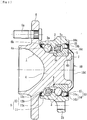
- Fig.1 is a longitudinal-sectional view of one embodiment of a wheel bearing apparatus of the present invention
- Fig. 2 is a partially enlarged view showing a detection portion of Fig. 1
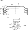
- Fig. 3(a) is an explanatory view showing a stacked state of the protection covers of Fig. 2
- Fig. 3(b) is an enlarged view of Fig. 3(a)
- Fig. 3(c) is an enlarged view showing a modification of the elastic member of Fig. 3(b)
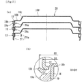
- Fig. 4(a) is an explanatory view showing a stacked state of protection covers being modification of Fig. 2
- Fig. 4(b) is an enlarged view of Fig.
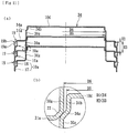
- Fig. 5(a) is an explanatory view showing a stacked state of protection covers being other modification of Fig. 2
- Fig. 5(b) is an enlarged view of Fig. 5(a)
- Fig. 6(a) is an explanatory view showing a stacked state of protection covers being other modification of Fig. 2
- Fig. 6(b) is an enlarged view of Fig. 6(a)
- Fig. 7(a) is an explanatory view showing a stacked state of protection covers being other modification of Fig. 2
- Fig. 7(b) is an enlarged view of Fig. 7(a)
- Fig. 7(b) is an enlarged view of Fig. 7(a)
- Fig. 7(b) is an enlarged view of Fig. 7(a)
- Fig. 7(a) is an explanatory view showing a stacked state of protection covers being other modification of Fig. 2
- Fig. 7(b) is an enlarged view of Fig.
- FIG. 8(a) is an explanatory view showing a stacked state of protection covers being other modification of Fig. 2
- Fig. 8(b) is an enlarged view of Fig. 8(a)
- Fig. 9(a) is an explanatory view showing a stacked state of protection covers being other modification of Fig. 2
- Fig. 9(b) is an enlarged view of Fig. 9(a)
- Fig. 10(a) is an explanatory view showing a stacked state of protection covers being modification of Fig. 9
- Fig. 10(b) is an enlarged view of Fig. 10(a)
- Fig. 11(a) is an explanatory view showing a stacked state of protection covers being other modification of Fig.
- Fig. 11(b) is an enlarged view of Fig. 11(a) .
- an outer-side of a bearing apparatus when it is mounted on a vehicle is referred to as “outer-side” (a left side in a drawing)
- an inner-side of a bearing apparatus when it is mounted on a vehicle is referred to as “inner side” (a right side in a drawing).
- the wheel bearing apparatus shown in Fig. 1 is a so-called "third generation" type for a driven wheel and comprises an inner member 1, an outer member 2, and double row rolling elements (balls) 3, 3 contained between the inner and outer members 1 and 2.
- the inner member 1 includes the hub wheel 4 and an inner ring 5 press-fitted onto the hub wheel 4 via a predetermined interference.
- the hub wheel 4 is integrally formed, on its outer-side end, with a wheel mounting flange 6 for mounting a wheel (not shown) and is formed, on its outer circumference, with one (outer-side) inner raceway surface 4a from which axially extends a cylindrical portion 4b. Hub bolts 6a are secured on the wheel mounting flange 6 at its circumferentially equidistant positions.
- the inner ring 5 is formed on its outer circumference with the other (inner-side) inner raceway surface 5a and press-fitted onto the cylindrical portion 4b of the hub wheel 4 via a predetermined interference to form a so-called back-to-back duplex bearing.
- the inner ring 5 is axially secured on the hub wheel 4 with being applied a predetermined bearing pre-pressure by a caulked portion 7 formed by plastically deforming the end of the cylindrical portion 4b of the hub wheel 4 radially outward.
- the hub wheel 4 is made of medium-high carbon steel such as S53C including carbon of 0.40 ⁇ 0.80% by weight and is hardened by high frequency induction hardening as having a surface hardness of 58 ⁇ 64 HRC over the inner raceway surface 4a and a region from an inner-side base 6b of the wheel mounting flange 6 to the cylindrical portion 4b.
- the caulked portion 7 is not hardened to keep hardness after forging less than 25 HRC. This enables to increase mechanical strength against the rotary bending load applied to the wheel mounting flange 6 and improve the anti-fretting strength of the cylindrical portion 4b on which the inner ring 5 is press-fitted and to perform the plastic deforming of the caulked portion 7 smoothly without causing micro cracking therein.
- the inner ring 5 is formed of high carbon chrome steel such as SUJ2 and dipping hardened to their cores as having hardness of 58 ⁇ 64 HRC and the rolling elements 3 are formed of high carbon chrome steel such as SUJ2 and hardened as having hardness of 62 ⁇ 67 HRC.
- the outer member 2 is formed, on its outer circumference, with body mount flange 2b adapted to be mounted on a knuckle (not shown) and also formed, on its inner circumference, with double row outer raceway surfaces 2a, 2a.
- the double row outer raceway surfaces 2a, 2a oppose to the inner raceway surfaces 4a, 5a of the inner member.
- the outer member 2 is formed of medium-high carbon steel such as S53C including carbon of 0.40 ⁇ 0.80% by weight and at least the outer raceway surfaces 2a, 2a are hardened by high frequency induction hardening as having a surface hardness of 58 ⁇ 64 HRC.
- the double row rolling elements 3, 3 are rollably contained between the inner and outer raceway surfaces 4a, 5a and 2a, 2a via cages 8.
- a seal 9 is mounted on the outer-side opening formed between the outer member 2 and inner member 1 and protection cover 10 is mounted on the inner-side opening in order to close and seal annular openings and to prevent leakage of lubricating grease sealed within the bearing and entering of rain water or dusts from the outside into the bearing.
- the outer-side seal 9 is formed as an integrated seal comprising a core metal 11 press-fitted into the outer-side end of the outer member 2 via a predetermined interface and a sealing member 12 adhered to the core metal 11 via by vulcanizing adhesion.
- the core metal 11 is press-formed of austenitic stainless steel sheet (JIS SUS 304 etc.) or cold rolled steel sheet (JIS SPCC etc.) so as to have an L-shaped cross-section.
- the sealing member 12 is formed of synthetic rubber such as NBR (acrylonitrile-butadiene rubber) and comprises a side lip 12a and a dust lip 12b inclined radially outward and slide-contacting with the inner-side base 6b having a circular-arc section of the wheel mounting flange 6 via a predetermined interference, and a grease lip 12c inclined toward the inner-side and slide-contacting with the base 6b of circular arc section via a predetermined interference.
- NBR acrylonitrile-butadiene rubber
- sealing member 12 there are examples of material of sealing member 12 other than NBR such as HNBR (hydrogenation acrylonitric-butadiene rubber), EPDM (ethylene propylene rubber), ACM (poly-acrylic rubber) superior in heat and chemical resistance, FKM (fluororubber) or silicone rubber.
- HNBR hydrogenation acrylonitric-butadiene rubber
- EPDM ethylene propylene rubber
- ACM poly-acrylic rubber
- FKM fluororubber
- silicone rubber silicone rubber
- the present invention is not limited to such a bearing and may be a double row tapered roller bearing using tapered rollers as rolling elements 3.
- the wheel bearing apparatus of third generation type the present invention can be applied to first and second generation type bearings (not shown) in which a pair of inner rings are press-fitted onto the cylindrical portion of the hub wheel.
- a pulser ring 13 is press-fitted onto the outer circumference of the inner ring 5.
- the pulser ring 13 comprises an annular support member 14 having a generally annular configuration and formed of a ferromagnetic steel plate such as ferritic stainless steel sheet (JIS SUS 430 etc.) or preserved cold rolled steel sheet by press working so as to have an L-shaped cross-section, and a magnetic encoder 15.
- the annular support member 14 comprises a cylindrical fitting portion 14a to be press-fitted onto the outer circumference of the inner ring 5 and an upright portion 14b extending radially outward from the cylindrical fitting portion 14a.
- the magnetic encoder 15 is integrally adhered to the upright portion 14b by vulcanizing adhesion.
- the magnetic encoder 15 is formed of elastomer such as rubber into which ferritic magnetic powder is mingled so that N and S poles are alternately arranged along its circumference to form a rotary encoder for detecting the rotation speed of wheel.
- a pulser ring 13 having the magnetic encoder 15 comprising rubber magnet
- other kinds of encoders such as a pulser ring of steel sheet formed with a plurality of through apertures or irregularities or formed of sintered alloy or that to which plastic magnet plate is adhered.
- a protection cover 10 is press-fitted into the inner circumference of the inner-side end of the outer member 2 to close the inner-side opening of the outer member 2.
- the protection cover 10 is formed of non-magnetic austenitic stainless steel sheet having anti-corrosion characteristics so as not to give adverse effect on sensing performance of a rotation speed sensor 16.
- the protection cover 10 has a cup-shaped configuration and comprises a cylindrical fitting portion 10a adapted to be press-fitted into the inner circumference of the inner-side end of the outer member 2, a disc-shaped shield portion 10b extending radially inward from the fitting portion 10a and opposing to the magnetic encoder 15 via a small axial gap, and a bottom portion 10d extending from the shield portion 10b via a bent portion 10c for covering the inner-side end of the inner member 1.
- the detection portion of the rotation speed sensor 16 is arranged so that it is adjacent to or contact to the shield portion 10b of the protection cover 10, and the detection portion of the rotation speed sensor 16 and the magnetic encoder 15 are opposed each other via the protection cover 10 with remaining a predetermined air gap (axial gap) therebetween.
- the rotation speed sensor 16 is formed of injection moldable synthetic resin such as PA66 in which an IC circuit incorporated with a Hall element, a magnetic resistance element (MR element), and a waveform shaping circuit for shaping the output waveform of the magnetic detecting element (not shown) are embedded and forms the ABS of an automobile for detecting the rotation speed of a wheel and controlling it.
- the fitting portion 10a of the protection cover 10 comprises a cylindrical portion 17 adapted to be metal-contact fitted into a cylindrical fitting surface 2c formed on the inner circumference of the end of the outer member 2 and a radially reduced portion 18 axially extending from the cylindrical portion 17.
- An elastic member 19 of synthetic rubber such as NBR is integrally adhered to the radially reduced portion 18 via vulcanizing adhesion.
- the elastic member 19 is adhered to the protection cover 10 so that it does not project to the inner-side from the shield portion 10b of the protection cover 10 to prevent the elastic member 19 from interfering the rotation speed sensor 16.
- the elastic member 19 comprises an annular projection 19a radially outwardly projecting from the outer circumference of the cylindrical portion 17 and a contact lip 19b radially outwardly extending with an inclination at the inner-side of the annular projection 19a.
- the fitting surface 2c and the chamfered portion 2d of the outer member 2 are simultaneously machined by cutting operations such as grinding or turning operations.
- cutting operations such as grinding or turning operations.
- the fitting surface 2c and chamfered portion 2d of the outer member 2 are simultaneously ground together with the double row outer raceway surfaces 2a, 2a after heat treatment by a formed grinding wheel, it is possible to improve the dimensional accuracy in roundness and coaxiality of the fitting surface 2c and the chamfered portion 2d and thus to reduce working steps and accordingly manufacturing cost.
- the protection covers thus manufactured are usually stacked each other during manufacturing steps as shown in Fig. 3(a) for space saving during stock or under wait for manufacturing operation.
- an outer diameter D1 of a tip end of the cylindrical portion 17 of the protection cover 10 is set smaller than an outer diameter D2 of a tip end of the contact lip 19b of the elastic member 19 (D1 ⁇ D2) as shown in Fig. 3(b) .
- This makes it possible to provide a wheel bearing apparatus which can prevent the contact lip 19b of a lower stacked protection cover 10 from being damaged or cut by the tip end of the cylindrical portion 17 of an upper stacked protection cover 10 when the protection covers are stacked each other and thus can improve the workability in manufacturing and transferring steps as well as reliability of quality.
- Fig. 4 shows a modification of the protection cover 10 of Fig. 2 .
- the protection cover 20 of this modification is basically different from the protection cover 10 only in structure of the fitting portion and accordingly same reference numerals are used for designating the same structural elements of the previously described embodiment and detailed description of them will be omitted.
- This protection cover 20 is press-formed of non-magnetic austenitic stainless steel sheet as having a cup-shaped configuration and comprises a cylindrical fitting portion 20a adapted to be press-fitted into the inner circumference of the inner-side end of the outer member (not shown), a disc-shaped shield portion 10b extending radially inward from the fitting portion 20a and a bottom portion 10d extending from the shield portion 10b via a bent portion 10c.
- the fitting portion 20a of the protection cover 20 comprises a cylindrical portion 21 to be metal-fitted into the fitting surface of the outer member and a radially reduced cylindrical portion 18 axially extending from the cylindrical portion 21.
- An elastic member 19' formed of synthetic resin such as NBR etc. is integrally adhered to the radially reduced portion 18.
- a chamfered portion 21a is formed on a tip end of the cylindrical portion 21 of the protection cover 20 and is designed so that it abuts against the root of the contact lip 19b and an inclination angle of the chamfered portion 21a corresponds to and is substantially same as that of the contact lip 19b.
- the wording "substantially same” means that the inclination angle of the chamfered portion 21a is simply a target value and accordingly there is substantially no difference between inclination angles of the chamfered portion 21a and the contact lip 19b. That is, difference in angles caused by manufacturing error should be allowed.
- Figs. 5 ⁇ 7 show other modifications of the protection cover 10 of Fig. 2 . These modifications are basically different from the previously described protection covers only in structure of the fitting portion and accordingly same reference numerals are used for designating the same structural elements of the previously described embodiment and detailed description of them will be omitted.
- the protection cover 22 shown in Fig. 5(a) is press-formed of non-magnetic austenitic stainless steel sheet as having a cup-shaped configuration and comprises a cylindrical fitting portion 22a adapted to be press-fitted into the inner circumference of the inner-side end of the outer member (not shown), a disc-shaped shield portion 10b extending radially inward from the fitting portion 22a and a bottom portion 10d extending from the shield portion 10b via a bent portion 10c.
- the fitting portion 22a of the protection cover 22 comprises a cylindrical portion 23 to be metal-fitted into the fitting surface of the outer member and a radially reduced cylindrical portion 18 axially extending from the cylindrical portion 23.
- An elastic member 19' formed of synthetic resin such as NBR etc. is integrally adhered to the radially reduced portion 18.
- a chamfered portion 23a having a circular arc surface is formed on a tip end of the cylindrical portion 23 of the protection cover 22 so that the chamfered portion 23a can abut against the root of the contact lip 19b. This makes it possible to easily press-fit the protection cover 22 into to the outer member and prevent the contact lip 19b from being damaged or cut.
- the protection cover 24 shown in Fig. 6(a) is press-formed of non-magnetic austenitic stainless steel sheet as having a cup-shaped configuration and comprises a cylindrical fitting portion 24a adapted to be press-fitted into the inner circumference of the inner-side end of the outer member (not shown), a disc-shaped shield portion 10b extending radially inward from the fitting portion 24a and a bottom portion 10d extending from the shield portion 10b via a bent portion 10c.
- the fitting portion 24a of the protection cover 24 comprises a cylindrical portion 25 to be metal-fitted into the fitting surface of the outer member and a radially reduced cylindrical portion 18 axially extending from the cylindrical portion 25.
- An elastic member 19 formed of synthetic resin such as NBR etc. is integrally adhered to the radially reduced portion 18.
- a bent edge 25a bent radially inward is formed on a tip end of the cylindrical portion 25 of the protection cover 24 so that the bent edge 25a can abut against the elastic member 19 avoiding the contact lip 19b. This makes it possible to easily press-fit the protection cover 24 into to the outer member and prevent the contact lip 19b from being damaged or cut.
- the protection cover 26 shown in Fig. 7(a) is press-formed of non-magnetic austenitic stainless steel sheet as having a cup-shaped configuration and comprises a cylindrical fitting portion 26a adapted to be press-fitted into the inner circumference of the inner-side end of the outer member (not shown), a disc-shaped shield portion 10b extending radially inward from the fitting portion 26a and a bottom portion 10d extending from the shield portion 10b via a bent portion 10c.
- the fitting portion 26a of the protection cover 26 comprises a cylindrical portion 27 to be metal-fitted into the fitting surface of the outer member and a radially reduced cylindrical portion 18 axially extending from the cylindrical portion 27.
- An elastic member 19 formed of synthetic resin such as NBR etc. is integrally adhered to the radially reduced portion 18.
- the bent edge 27a bent radially inward at a right angle is formed on the end of the cylindrical portion 27 so that the end face of the bent edge 27a can abut against the elastic member 19. This makes it possible to easily press-fit the protection cover 26 into to the outer member and prevent the contact lip 19b from being damaged or cut.
- Fig. 8 shows further modification of the protection cover 10 of Fig. 2 .
- This modification is basically different from the previously described protection covers only in structure of the elastic member 19 of the protection cover 10 accordingly same reference numerals are used for designating the same structural elements of the previously described embodiments and detailed description of them will be omitted.
- This protection cover 28 shown in Fig. 8(a) is press-formed of non-magnetic austenitic stainless steel sheet as having a cup-shaped configuration and comprises a cylindrical fitting portion 10a adapted to be press-fitted into the inner circumference of the inner-side end of the outer member (not shown), a disc-shaped shield portion 10b extending radially inward from the fitting portion 10a and a bottom portion 10d extending from the shield portion 10b via a bent portion 10c.
- the fitting portion 10a of the protection cover 28 comprises a cylindrical portion 17 to be metal-fitted into the fitting surface of the outer member and a radially reduced cylindrical portion 18 axially extending from the cylindrical portion 17.
- An elastic member 29 formed of synthetic resin such as NBR etc. is integrally adhered to the radially reduced portion 18.
- the elastic member 29 comprises an annular projection 19a radially outwardly projecting from the outer circumference of the cylindrical portion 17 and a contact lip 19b radially outwardly extending with an inclination at the inner-side of the annular projection 19a, and a cylindrical guide portion 29a is integrally formed on the elastic member 29 radially inward of the contact lip 19b so that its side surface becomes flush with a side surface of the shield portion 10b, and an outer diameter D3 of the guide portion 29a is set smaller than an inner diameter D4 of the cylindrical portion 17 of the protection cover 28 (D3 ⁇ D4) with remaining a guiding gap therebetween.
- This makes it possible to improve the stability of the stacked state of the protection covers 28 and the workability in their manufacture since the cylindrical portion 17 of the upper protection cover 28 is radially guided by the guide portion 29a of the lower protection cover 28.
- Fig. 9 shows further modification of the protection cover 10 of Fig. 2 .
- This modification is basically different from the previously described protection covers only in configuration of the metallic portion of the protection cover 10 accordingly same reference numerals are used for designating the same structural elements of the previously described embodiments and detailed description of them will be omitted.
- This protection cover 30 shown in Fig. 9(a) is press-formed of non-magnetic austenitic stainless steel sheet as having a cup-shaped configuration and comprises a cylindrical fitting portion 10a adapted to be press-fitted into the inner circumference of the inner-side end of the outer member (not shown), a disc-shaped shield portion 10b extending radially inward from the fitting portion 10a, a bent portion 30a bent from the shield portion 10b at a right angle, and a bottom portion 10d extending from the bent portion 30a radially inward.
- the protection cover 30 is formed as having configurations and dimensions so that metallic portions of mutually adjacent protection covers 30 contact each other before the cylindrical portions 17 are abutted against the elastic members 19 when the protection covers 30 are stacked each other. More particularly, since the bent portion 30a is bent from the shield portion 10b at a right angle, it is designed so that the metallic portions of the upper and lower protection covers 30 are firstly abutted each other and a height H2 of the fitting portion 10a is smaller than a height H3 from shield portion 10b of the upper protection cover 30 to the side surface of the elastic member 19 of the lower protection cover 30 when the upper and lower protection covers 30 are stacked each other (H2 ⁇ H3).
- a corner portion between the bent portion 30a and the shield portion 10b of the upper protection cover 30 abuts against a corner portion between the bottom portion 10d and the bent portion 30a of the lower protection cover 30 and accordingly it is possible to avoid the metallic fitting portion 10a from contacting the elastic member 19 and thus prevent the contact lip 19b from being damaged and cut.
- Figs. 10 and 11 show modifications of the protection cover 30 of Fig. 9 .
- This modification is basically different from the previously described protection covers only in configuration of the metallic portion of the protection cover 30 accordingly same reference numerals are used for designating the same structural elements of the previously described embodiments and detailed description of them will be omitted.
- This protection cover 31 shown in Fig. 10(a) is press-formed of non-magnetic austenitic stainless steel sheet as having a cup-shaped configuration and comprises a cylindrical fitting portion 10a adapted to be press-fitted into the inner circumference of the inner-side end of the outer member (not shown), a disc-shaped shield portion 31a extending radially inward from the fitting portion 10a, a bent portion 30a bent from the shield portion 31a at a right angle, and a bottom portion 31b extending from the bent portion 30a radially inward.
- the protection cover 31 of this modification is formed as having configurations and dimensions so that metallic portions of mutually adjacent protection covers 31 contact each other before the metallic cylindrical portions 17 are abutted against the elastic members 19 when the protection covers 31 are stacked each other. More particularly, it is so designed that a height H2 of the fitting portion 10a is smaller than a height H3 from the shield portion 31a of the upper protection cover 31 to the side surface of the elastic member 19 of the lower protection cover 31 when the upper and lower protection covers 31 are stacked each other (H2 ⁇ H3).
- a corner portion 32 between the bent portion 30a and the shield portion 31a as well as a corner portion 33 between the bent portion 30a and bottom portion 31b are formed as having a tapered configuration.
- This causes abutment of the corner portion 32 between the bent portion 30a and the shield portion 31a of the upper protection cover 31 and the corner portion 33 between the bent portion 30a and bottom portion 31b of the lower protection cover 31. Accordingly, this makes it possible to avoid the metallic cylindrical portion 17 from contacting the elastic member 19 and thus prevent the contact lip 19b from being damaged.
- it enables the corner portions 32 and 33 of the upper and lower protection covers 31 to be surface-contacted each other and thus to improve the stability when stacked and workability during manufacturing steps.
- a protection cover 34 shown in Fig. 11(a) is press-formed of non-magnetic austenitic stainless steel sheet as having a cup-shaped configuration and comprises a cylindrical fitting portion 10a adapted to be press-fitted into the inner circumference of the inner-side end of the outer member (not shown), a disc-shaped shield portion 31a extending radially inward from the fitting portion 10a, a bent portion 30a bent from the shield portion 31a at a right angle, a radially reduced cylindrical portion 34b axially extending from the bent portion 30a via a tapered stepped portion 34a, and a bottom portion 10d extending from the radially reduced portion 34a radially inward.
- the protection cover 34 is formed as having configurations and dimensions so that metallic portions of mutually adjacent protection covers 34 contact each other before the metallic cylindrical portions 17 are abutted against the elastic members 19 when the protection covers 34 are stacked each other.
- an outer diameter D5 of the radially reduced portion 34b is smaller than an inner diameter D6 of the bent portion 30a with remaining a small radial gap therebetwen (D5 ⁇ D6) to enable the bent portion 30a of the upper protection cover 34 to be fitted over the radially reduced portion 34b of the lower protection cover 34 as well as that a height H2 of the fitting portion 10a is smaller than a height H3 from the shield portion 31a of the upper protection cover 34 to the side surface of the elastic member 19 of the lower protection cover 34 when the protection covers 34 are stacked (H2 ⁇ H3).
- the corner portion 32 between the bent portion 30a and the shield portion 31a of the upper protection cover 34 contacts the stepped portion 34a of the lower protection cover 34.
- the wheel bearing apparatus of the present invention can be applied to any wheel bearing apparatus for a driven wheel of inner ring rotation type having a protection cover on an outer member and using balls or tapered rollers as rolling elements.
Landscapes
- Engineering & Computer Science (AREA)
- General Engineering & Computer Science (AREA)
- Mechanical Engineering (AREA)
- Rolling Contact Bearings (AREA)
- Sealing Of Bearings (AREA)
Claims (8)
- Couvercle de protection en acier en forme de coupe (30, 31, 34) d'un appareil de roulement pour roue, l'appareil de roulement pour roue comprenant :un élément externe (2) formé de manière intégrée sur sa circonférence interne avec des doubles surfaces de circuit externe de rangée (2a, 2a) ;un élément interne (1) comprenant une roue de moyeu (4) et au moins un anneau interne (5), la roue de moyeu (4) étant formée de manière intégrée sur son une extrémité avec une bride de fixation de roue (6) et ayant une section cylindrique (4b) s'étendant axialement à partir de la bride de fixation de roue (6), l'anneau interne (5) étant ajusté sous pression sur la section cylindrique (4b) de la roue de moyeu (4), l'élément interne (1) étant formé sur ses circonférences externes avec des doubles surfaces de circuit interne de rangée (4a, 5a) opposées aux doubles surfaces de circuit externe de rangée (2a, 2a) ;des doubles éléments de roulement de rangée (3, 3) contenus entre les surfaces de circuit externe (2a, 2a) et les surfaces de circuit interne (4a, 5a) respectivement de l'élément externe (2) et de l'élément interne (1) ; etle couvercle de protection en acier en forme de coupe (30, 31, 34) monté sur l'extrémité de côté interne de l'élément externe (2) ; le couvercle de protection (30, 31, 34) comprenant une section d'ajustement cylindrique (10a) adaptée pour être ajustée sous pression dans la circonférence interne de l'extrémité de côté interne de l'élément externe (2), une section de bouclier en forme de disque (10b, 31a) s'étendant radialement vers l'intérieur de la section d'ajustement (10a) et une section de partie inférieure (10d, 31b) s'étendant de la section de bouclier (10b, 31a) via une section courbée (30a) pour recouvrir l'extrémité de côté interne de l'élément interne (1) ; la section d'ajustement (10a) du couvercle de protection (30, 31, 34) comprenant une section cylindrique (17) adaptée pour être ajustée par contact métallique dans une surface d'ajustement cylindrique (2c) formée sur la circonférence interne de l'extrémité de l'élément externe (2) etune section de réduction radiale (18) s'étendant axialement à partir de la section cylindrique (17) ;un élément élastique (19) de caoutchouc synthétique étant collé de manière intégrée à la section de réduction radiale (18) via une adhésion par vulcanisation,l'élément élastique (19) comprenant une projection annulaire (19a) se projetant vers l'extérieur radialement à partir de la circonférence externe de la section cylindrique (17) ; etquand le couvercle de protection (30, 31, 34) est ajusté dans l'élément externe (2), la projection annulaire (19a) étant étroitement en contact avec la surface d'ajustement (2c) en étant déformée élastiquement,caractérisé en ce que- l'élément élastique (19) comprend une lèvre de contact (19b) s'étendant vers l'extérieur radialement avec une inclinaison au côté interne de la projection annulaire (19a) ;- quand le couvercle de protection (30, 31, 34) est ajusté dans l'élément externe (2), la lèvre de contact (19b) est en contact élastique avec l'extrémité de côté interne de l'élément externe (2) ;- la section courbée (30a) est formée comme étant courbée à un angle droit par rapport à la section de bouclier (10b, 31a) et le couvercle de protection (30, 31, 34) est formé comme ayant des configurations et des dimensions de sorte que des parties métalliques de couvercles de protection mutuellement adjacents entrent en contact l'un avec l'autre avant que les sections cylindriques (17) ne jouxtent les éléments élastiques (19) quand les couvercles de protection (30, 31, 34) sont empilés l'un sur l'autre, moyennant quoi une hauteur (H2) de la section d'ajustement (10a) est plus petite qu'une hauteur (H3) d'une section de bouclier (10b, 31a) d'un couvercle de protection supérieur (30, 31, 34) à la surface latérale de l'élément élastique (19) d'un couvercle de protection inférieur (30, 31) quand les couvercles de protection supérieur et inférieur sont empilés l'un sur l'autre (H2 < H3).
- Couvercle de protection en acier en forme de coupe (30, 31, 34) d'un appareil de roulement pour roue selon la revendication 1 avec lequel un anneau impulseur (13) de ses caractéristiques magnétiques étant changé en alternance le long de sa direction circonférentielle est ajusté sur l'anneau interne (5), et le couvercle de protection (10) étant formé d'une feuille en acier inoxydable austénitique non magnétique et un capteur de vitesse de rotation (16) est disposé de manière opposée à l'anneau impulseur (13) tout en étant séparé par un espace libre d'air axial via le couvercle de protection (10).
- Couvercle de protection en acier en forme de coupe (30, 31, 34) d'un appareil de roulement pour roue selon la revendication 1 ou 2 avec lequel un diamètre externe (D1) d'une extrémité de pointe de la section cylindrique (17) du couvercle de protection (10) est réglé plus petit qu'un diamètre externe (D2) d'une extrémité de pointe de la lèvre de contact (19b) de l'élément élastique (19) (D1 < D2).
- Couvercle de protection en acier en forme de coupe (30, 31, 34) d'un appareil de roulement pour roue selon la revendication 1 avec lequel une section chanfreinée (21a) ayant une surface plate inclinée est formée sur une extrémité de pointe de la section cylindrique (21) du couvercle de protection (20) et un angle d'inclinaison de la section chanfreinée (21a) correspond à celui de la lèvre de contact (19b).
- Couvercle de protection en acier en forme de coupe (30, 31, 34) d'un appareil de roulement pour roue selon la revendication 1 avec lequel une section chanfreinée (23a) ayant une surface d'arc circulaire est formée sur une extrémité de pointe de la section cylindrique (23) du couvercle de protection (22).
- Couvercle de protection en acier en forme de coupe (30, 31, 34) d'un appareil de roulement pour roue selon la revendication 1 avec lequel un bord courbé (25a ou 27a) courbé radialement vers l'intérieur est formé sur une extrémité de pointe de la section cylindrique (25 ou 27) du couvercle de protection (24 ou 26).
- Couvercle de protection en acier en forme de coupe (30, 31, 34) d'un appareil de roulement pour roue selon la revendication 1 avec lequel une section de guide cylindrique (29a) est formée de manière intégrée sur l'élément élastique (29) radialement vers l'intérieur de la lèvre de contact (19b) et un diamètre externe (D3) de la section de guide (29a) est réglé plus petit qu'un diamètre interne (D4) de la section cylindrique (17) du couvercle de protection (28) (D3 < D4), restant un espace libre de guidage entre eux.
- Couvercle de protection en acier en forme de coupe (30, 31, 34) d'un appareil de roulement pour roue selon la revendication 1 avec lequel le couvercle de protection (34) comprend une section cylindrique plus petite (34b) s'étendant axialement à partir de la section courbée (30a) via une section échelonnée en forme de pointe (34a) et ayant un diamètre plus petit que celui de la section courbée (30a).
Applications Claiming Priority (2)
| Application Number | Priority Date | Filing Date | Title |
|---|---|---|---|
| JP2014048278A JP6274921B2 (ja) | 2014-03-12 | 2014-03-12 | 車輪用軸受装置 |
| PCT/JP2015/057203 WO2015137415A1 (fr) | 2014-03-12 | 2015-03-11 | Dispositif de palier de roue |
Publications (3)
| Publication Number | Publication Date |
|---|---|
| EP3121468A1 EP3121468A1 (fr) | 2017-01-25 |
| EP3121468A4 EP3121468A4 (fr) | 2017-09-20 |
| EP3121468B1 true EP3121468B1 (fr) | 2020-01-01 |
Family
ID=54071854
Family Applications (1)
| Application Number | Title | Priority Date | Filing Date |
|---|---|---|---|
| EP15760991.8A Active EP3121468B1 (fr) | 2014-03-12 | 2015-03-11 | Dispositif de palier de roue |
Country Status (5)
| Country | Link |
|---|---|
| US (1) | US9989094B2 (fr) |
| EP (1) | EP3121468B1 (fr) |
| JP (1) | JP6274921B2 (fr) |
| CN (1) | CN106104034B (fr) |
| WO (1) | WO2015137415A1 (fr) |
Cited By (1)
| Publication number | Priority date | Publication date | Assignee | Title |
|---|---|---|---|---|
| DE102021105774A1 (de) | 2021-03-10 | 2022-09-15 | Schaeffler Technologies AG & Co. KG | Dichtring |
Families Citing this family (5)
| Publication number | Priority date | Publication date | Assignee | Title |
|---|---|---|---|---|
| JP6398484B2 (ja) * | 2014-09-02 | 2018-10-03 | 日本精工株式会社 | エンコーダ付転がり軸受ユニット |
| JP6774363B2 (ja) * | 2017-03-24 | 2020-10-21 | Ntn株式会社 | 車輪用軸受装置 |
| WO2018230660A1 (fr) | 2017-06-16 | 2018-12-20 | 学校法人慶應義塾 | Procédé de mesure de chlore résiduel et appareil de mesure de chlore résiduel |
| JP7119919B2 (ja) | 2018-11-05 | 2022-08-17 | 日本精工株式会社 | ハブユニット軸受 |
| TWI796145B (zh) * | 2022-02-24 | 2023-03-11 | 鼎朋企業股份有限公司 | 研磨工具保持件的防塵結構 |
Citations (1)
| Publication number | Priority date | Publication date | Assignee | Title |
|---|---|---|---|---|
| US20120177312A1 (en) * | 2009-09-17 | 2012-07-12 | Ntn Corporation | Wheel Bearing Apparatus Incorporated With A Rotational Speed Detecting Apparatus |
Family Cites Families (13)
| Publication number | Priority date | Publication date | Assignee | Title |
|---|---|---|---|---|
| JPH0681069B2 (ja) | 1988-06-30 | 1994-10-12 | 日本電気株式会社 | アンテナ故障検出機能付送受信機 |
| JPH0629538Y2 (ja) * | 1989-02-27 | 1994-08-10 | 内山工業株式会社 | ベアリングシール |
| DE10037530A1 (de) * | 1999-08-31 | 2001-03-22 | Ntn Toyo Bearing Co Ltd | Dichtungsvorrichtung für Lager |
| JP5109369B2 (ja) * | 2006-12-28 | 2012-12-26 | 株式会社ジェイテクト | 車輪用転がり軸受装置 |
| JP5170369B2 (ja) * | 2007-04-10 | 2013-03-27 | Nok株式会社 | 密封装置 |
| DE112009002661B4 (de) * | 2008-10-29 | 2022-08-25 | Ntn Corporation | Radlagervorrichtung mit eingegliederter Radgeschwindigkeitserkennungsvorrichtung |
| JP5327077B2 (ja) * | 2009-01-26 | 2013-10-30 | 日本精工株式会社 | エンコーダ付車輪支持用転がり軸受ユニット |
| JP5592130B2 (ja) * | 2010-03-18 | 2014-09-17 | Ntn株式会社 | 回転速度検出装置付き車輪用軸受装置 |
| JP5528278B2 (ja) * | 2010-09-22 | 2014-06-25 | Ntn株式会社 | 車輪用軸受装置 |
| CN103443486B (zh) * | 2011-03-09 | 2016-04-06 | Ntn株式会社 | 车轮轴承装置 |
| JP2012202415A (ja) * | 2011-03-23 | 2012-10-22 | Ntn Corp | 回転速度検出装置付き車輪用軸受装置 |
| JP2012232708A (ja) * | 2011-05-09 | 2012-11-29 | Nsk Ltd | 車輪支持用転がり軸受ユニット |
| JP5979775B2 (ja) * | 2012-02-10 | 2016-08-31 | 内山工業株式会社 | 軸受装置用キャップ |
-
2014
- 2014-03-12 JP JP2014048278A patent/JP6274921B2/ja active Active
-
2015
- 2015-03-11 CN CN201580012980.XA patent/CN106104034B/zh active Active
- 2015-03-11 EP EP15760991.8A patent/EP3121468B1/fr active Active
- 2015-03-11 WO PCT/JP2015/057203 patent/WO2015137415A1/fr not_active Ceased
-
2016
- 2016-09-10 US US15/261,888 patent/US9989094B2/en active Active
Patent Citations (1)
| Publication number | Priority date | Publication date | Assignee | Title |
|---|---|---|---|---|
| US20120177312A1 (en) * | 2009-09-17 | 2012-07-12 | Ntn Corporation | Wheel Bearing Apparatus Incorporated With A Rotational Speed Detecting Apparatus |
Cited By (1)
| Publication number | Priority date | Publication date | Assignee | Title |
|---|---|---|---|---|
| DE102021105774A1 (de) | 2021-03-10 | 2022-09-15 | Schaeffler Technologies AG & Co. KG | Dichtring |
Also Published As
| Publication number | Publication date |
|---|---|
| JP6274921B2 (ja) | 2018-02-07 |
| EP3121468A4 (fr) | 2017-09-20 |
| CN106104034B (zh) | 2018-10-23 |
| US9989094B2 (en) | 2018-06-05 |
| US20170067509A1 (en) | 2017-03-09 |
| WO2015137415A1 (fr) | 2015-09-17 |
| EP3121468A1 (fr) | 2017-01-25 |
| CN106104034A (zh) | 2016-11-09 |
| JP2015172401A (ja) | 2015-10-01 |
Similar Documents
| Publication | Publication Date | Title |
|---|---|---|
| EP2641750B1 (fr) | Dispositif de palier conçu pour être utilisé dans une roue et doté d'un dispositif de détection de vitesse de rotation | |
| US8915649B2 (en) | Wheel bearing apparatus | |
| US8585298B2 (en) | Wheel bearing apparatus incorporated with a rotation speed detecting apparatus | |
| JP5528278B2 (ja) | 車輪用軸受装置 | |
| JP5914585B2 (ja) | 車輪用軸受装置 | |
| EP3121468B1 (fr) | Dispositif de palier de roue | |
| EP2980432B1 (fr) | Dispositif de roulement de roue | |
| JP5894389B2 (ja) | 車輪用軸受装置 | |
| JP2010151277A (ja) | 回転速度検出装置付き車輪用軸受装置 | |
| CN107542776B (zh) | 车轮用轴承装置 | |
| US10343454B2 (en) | Bearing device for vehicle wheel | |
| US10598226B2 (en) | Bearing device for vehicle wheel | |
| JP2013079701A (ja) | 車輪用軸受装置 | |
| JP6012803B2 (ja) | 車輪用軸受装置 | |
| JP2014190464A (ja) | 車輪用軸受装置 | |
| JP2016078512A (ja) | 車輪用軸受装置 | |
| JP6671909B2 (ja) | エンコーダリングを備えた密封装置の圧入方法 | |
| JP2012202415A (ja) | 回転速度検出装置付き車輪用軸受装置 | |
| JP6320092B2 (ja) | 車輪用軸受装置 | |
| JP2018087640A (ja) | 車輪用軸受装置 | |
| JP2009186250A (ja) | 磁気エンコーダ及び磁気エンコーダを備えた車輪用軸受装置 |
Legal Events
| Date | Code | Title | Description |
|---|---|---|---|
| STAA | Information on the status of an ep patent application or granted ep patent |
Free format text: STATUS: THE INTERNATIONAL PUBLICATION HAS BEEN MADE |
|
| PUAI | Public reference made under article 153(3) epc to a published international application that has entered the european phase |
Free format text: ORIGINAL CODE: 0009012 |
|
| STAA | Information on the status of an ep patent application or granted ep patent |
Free format text: STATUS: REQUEST FOR EXAMINATION WAS MADE |
|
| 17P | Request for examination filed |
Effective date: 20161011 |
|
| AK | Designated contracting states |
Kind code of ref document: A1 Designated state(s): AL AT BE BG CH CY CZ DE DK EE ES FI FR GB GR HR HU IE IS IT LI LT LU LV MC MK MT NL NO PL PT RO RS SE SI SK SM TR |
|
| AX | Request for extension of the european patent |
Extension state: BA ME |
|
| DAV | Request for validation of the european patent (deleted) | ||
| DAX | Request for extension of the european patent (deleted) | ||
| A4 | Supplementary search report drawn up and despatched |
Effective date: 20170822 |
|
| RIC1 | Information provided on ipc code assigned before grant |
Ipc: F16C 41/00 20060101ALI20170816BHEP Ipc: B60B 35/18 20060101ALI20170816BHEP Ipc: B60B 27/02 20060101ALN20170816BHEP Ipc: F16C 33/78 20060101ALI20170816BHEP Ipc: F16C 33/72 20060101ALI20170816BHEP Ipc: B60B 35/02 20060101ALI20170816BHEP Ipc: F16C 41/04 20060101ALI20170816BHEP Ipc: F16J 15/32 20160101ALI20170816BHEP Ipc: F16J 15/10 20060101ALI20170816BHEP Ipc: B60B 27/00 20060101ALI20170816BHEP Ipc: F16C 19/18 20060101ALI20170816BHEP Ipc: B60B 7/00 20060101ALI20170816BHEP Ipc: F16C 33/76 20060101AFI20170816BHEP |
|
| STAA | Information on the status of an ep patent application or granted ep patent |
Free format text: STATUS: EXAMINATION IS IN PROGRESS |
|
| 17Q | First examination report despatched |
Effective date: 20180405 |
|
| RIC1 | Information provided on ipc code assigned before grant |
Ipc: F16C 33/78 20060101ALI20181009BHEP Ipc: F16C 33/76 20060101AFI20181009BHEP Ipc: F16C 41/00 20060101ALI20181009BHEP Ipc: B60B 27/02 20060101ALN20181009BHEP Ipc: F16J 15/10 20060101ALI20181009BHEP Ipc: B60B 35/02 20060101ALI20181009BHEP Ipc: B60B 35/18 20060101ALI20181009BHEP Ipc: F16C 41/04 20060101ALI20181009BHEP Ipc: B60B 7/00 20060101ALI20181009BHEP Ipc: B60B 27/00 20060101ALI20181009BHEP Ipc: F16C 19/18 20060101ALI20181009BHEP Ipc: F16C 33/72 20060101ALI20181009BHEP Ipc: F16J 15/32 20160101ALI20181009BHEP |
|
| GRAP | Despatch of communication of intention to grant a patent |
Free format text: ORIGINAL CODE: EPIDOSNIGR1 |
|
| STAA | Information on the status of an ep patent application or granted ep patent |
Free format text: STATUS: GRANT OF PATENT IS INTENDED |
|
| RIC1 | Information provided on ipc code assigned before grant |
Ipc: B60B 35/02 20060101ALI20190619BHEP Ipc: F16J 15/10 20060101ALI20190619BHEP Ipc: F16C 41/04 20060101ALI20190619BHEP Ipc: B60B 7/00 20060101ALI20190619BHEP Ipc: F16C 19/18 20060101ALI20190619BHEP Ipc: B60B 35/18 20060101ALI20190619BHEP Ipc: F16C 41/00 20060101ALI20190619BHEP Ipc: B60B 27/00 20060101ALI20190619BHEP Ipc: F16C 33/78 20060101ALI20190619BHEP Ipc: F16C 33/76 20060101AFI20190619BHEP Ipc: B60B 27/02 20060101ALN20190619BHEP Ipc: F16C 33/72 20060101ALI20190619BHEP Ipc: F16J 15/32 20160101ALI20190619BHEP |
|
| RIC1 | Information provided on ipc code assigned before grant |
Ipc: F16C 33/76 20060101AFI20190703BHEP Ipc: F16C 33/78 20060101ALI20190703BHEP Ipc: F16C 41/00 20060101ALI20190703BHEP Ipc: F16C 41/04 20060101ALI20190703BHEP Ipc: F16J 15/32 20160101ALI20190703BHEP Ipc: F16C 33/72 20060101ALI20190703BHEP Ipc: B60B 27/02 20060101ALN20190703BHEP Ipc: F16C 19/18 20060101ALI20190703BHEP Ipc: B60B 7/00 20060101ALI20190703BHEP Ipc: B60B 35/18 20060101ALI20190703BHEP Ipc: F16J 15/10 20060101ALI20190703BHEP Ipc: B60B 27/00 20060101ALI20190703BHEP Ipc: B60B 35/02 20060101ALI20190703BHEP |
|
| INTG | Intention to grant announced |
Effective date: 20190715 |
|
| GRAS | Grant fee paid |
Free format text: ORIGINAL CODE: EPIDOSNIGR3 |
|
| GRAA | (expected) grant |
Free format text: ORIGINAL CODE: 0009210 |
|
| STAA | Information on the status of an ep patent application or granted ep patent |
Free format text: STATUS: THE PATENT HAS BEEN GRANTED |
|
| AK | Designated contracting states |
Kind code of ref document: B1 Designated state(s): AL AT BE BG CH CY CZ DE DK EE ES FI FR GB GR HR HU IE IS IT LI LT LU LV MC MK MT NL NO PL PT RO RS SE SI SK SM TR |
|
| REG | Reference to a national code |
Ref country code: GB Ref legal event code: FG4D |
|
| REG | Reference to a national code |
Ref country code: CH Ref legal event code: EP Ref country code: AT Ref legal event code: REF Ref document number: 1220131 Country of ref document: AT Kind code of ref document: T Effective date: 20200115 |
|
| REG | Reference to a national code |
Ref country code: IE Ref legal event code: FG4D |
|
| REG | Reference to a national code |
Ref country code: DE Ref legal event code: R096 Ref document number: 602015044715 Country of ref document: DE |
|
| REG | Reference to a national code |
Ref country code: NL Ref legal event code: MP Effective date: 20200101 |
|
| REG | Reference to a national code |
Ref country code: LT Ref legal event code: MG4D |
|
| PG25 | Lapsed in a contracting state [announced via postgrant information from national office to epo] |
Ref country code: NO Free format text: LAPSE BECAUSE OF FAILURE TO SUBMIT A TRANSLATION OF THE DESCRIPTION OR TO PAY THE FEE WITHIN THE PRESCRIBED TIME-LIMIT Effective date: 20200401 Ref country code: RS Free format text: LAPSE BECAUSE OF FAILURE TO SUBMIT A TRANSLATION OF THE DESCRIPTION OR TO PAY THE FEE WITHIN THE PRESCRIBED TIME-LIMIT Effective date: 20200101 Ref country code: FI Free format text: LAPSE BECAUSE OF FAILURE TO SUBMIT A TRANSLATION OF THE DESCRIPTION OR TO PAY THE FEE WITHIN THE PRESCRIBED TIME-LIMIT Effective date: 20200101 Ref country code: CZ Free format text: LAPSE BECAUSE OF FAILURE TO SUBMIT A TRANSLATION OF THE DESCRIPTION OR TO PAY THE FEE WITHIN THE PRESCRIBED TIME-LIMIT Effective date: 20200101 Ref country code: NL Free format text: LAPSE BECAUSE OF FAILURE TO SUBMIT A TRANSLATION OF THE DESCRIPTION OR TO PAY THE FEE WITHIN THE PRESCRIBED TIME-LIMIT Effective date: 20200101 Ref country code: LT Free format text: LAPSE BECAUSE OF FAILURE TO SUBMIT A TRANSLATION OF THE DESCRIPTION OR TO PAY THE FEE WITHIN THE PRESCRIBED TIME-LIMIT Effective date: 20200101 Ref country code: PT Free format text: LAPSE BECAUSE OF FAILURE TO SUBMIT A TRANSLATION OF THE DESCRIPTION OR TO PAY THE FEE WITHIN THE PRESCRIBED TIME-LIMIT Effective date: 20200527 |
|
| PG25 | Lapsed in a contracting state [announced via postgrant information from national office to epo] |
Ref country code: GR Free format text: LAPSE BECAUSE OF FAILURE TO SUBMIT A TRANSLATION OF THE DESCRIPTION OR TO PAY THE FEE WITHIN THE PRESCRIBED TIME-LIMIT Effective date: 20200402 Ref country code: HR Free format text: LAPSE BECAUSE OF FAILURE TO SUBMIT A TRANSLATION OF THE DESCRIPTION OR TO PAY THE FEE WITHIN THE PRESCRIBED TIME-LIMIT Effective date: 20200101 Ref country code: LV Free format text: LAPSE BECAUSE OF FAILURE TO SUBMIT A TRANSLATION OF THE DESCRIPTION OR TO PAY THE FEE WITHIN THE PRESCRIBED TIME-LIMIT Effective date: 20200101 Ref country code: BG Free format text: LAPSE BECAUSE OF FAILURE TO SUBMIT A TRANSLATION OF THE DESCRIPTION OR TO PAY THE FEE WITHIN THE PRESCRIBED TIME-LIMIT Effective date: 20200401 Ref country code: IS Free format text: LAPSE BECAUSE OF FAILURE TO SUBMIT A TRANSLATION OF THE DESCRIPTION OR TO PAY THE FEE WITHIN THE PRESCRIBED TIME-LIMIT Effective date: 20200501 Ref country code: SE Free format text: LAPSE BECAUSE OF FAILURE TO SUBMIT A TRANSLATION OF THE DESCRIPTION OR TO PAY THE FEE WITHIN THE PRESCRIBED TIME-LIMIT Effective date: 20200101 |
|
| REG | Reference to a national code |
Ref country code: DE Ref legal event code: R097 Ref document number: 602015044715 Country of ref document: DE |
|
| PG25 | Lapsed in a contracting state [announced via postgrant information from national office to epo] |
Ref country code: ES Free format text: LAPSE BECAUSE OF FAILURE TO SUBMIT A TRANSLATION OF THE DESCRIPTION OR TO PAY THE FEE WITHIN THE PRESCRIBED TIME-LIMIT Effective date: 20200101 Ref country code: SK Free format text: LAPSE BECAUSE OF FAILURE TO SUBMIT A TRANSLATION OF THE DESCRIPTION OR TO PAY THE FEE WITHIN THE PRESCRIBED TIME-LIMIT Effective date: 20200101 Ref country code: MC Free format text: LAPSE BECAUSE OF FAILURE TO SUBMIT A TRANSLATION OF THE DESCRIPTION OR TO PAY THE FEE WITHIN THE PRESCRIBED TIME-LIMIT Effective date: 20200101 Ref country code: EE Free format text: LAPSE BECAUSE OF FAILURE TO SUBMIT A TRANSLATION OF THE DESCRIPTION OR TO PAY THE FEE WITHIN THE PRESCRIBED TIME-LIMIT Effective date: 20200101 Ref country code: SM Free format text: LAPSE BECAUSE OF FAILURE TO SUBMIT A TRANSLATION OF THE DESCRIPTION OR TO PAY THE FEE WITHIN THE PRESCRIBED TIME-LIMIT Effective date: 20200101 Ref country code: DK Free format text: LAPSE BECAUSE OF FAILURE TO SUBMIT A TRANSLATION OF THE DESCRIPTION OR TO PAY THE FEE WITHIN THE PRESCRIBED TIME-LIMIT Effective date: 20200101 Ref country code: RO Free format text: LAPSE BECAUSE OF FAILURE TO SUBMIT A TRANSLATION OF THE DESCRIPTION OR TO PAY THE FEE WITHIN THE PRESCRIBED TIME-LIMIT Effective date: 20200101 |
|
| REG | Reference to a national code |
Ref country code: CH Ref legal event code: PL |
|
| PLBE | No opposition filed within time limit |
Free format text: ORIGINAL CODE: 0009261 |
|
| STAA | Information on the status of an ep patent application or granted ep patent |
Free format text: STATUS: NO OPPOSITION FILED WITHIN TIME LIMIT |
|
| REG | Reference to a national code |
Ref country code: AT Ref legal event code: MK05 Ref document number: 1220131 Country of ref document: AT Kind code of ref document: T Effective date: 20200101 |
|
| 26N | No opposition filed |
Effective date: 20201002 |
|
| REG | Reference to a national code |
Ref country code: BE Ref legal event code: MM Effective date: 20200331 |
|
| PG25 | Lapsed in a contracting state [announced via postgrant information from national office to epo] |
Ref country code: LU Free format text: LAPSE BECAUSE OF NON-PAYMENT OF DUE FEES Effective date: 20200311 |
|
| PG25 | Lapsed in a contracting state [announced via postgrant information from national office to epo] |
Ref country code: AT Free format text: LAPSE BECAUSE OF FAILURE TO SUBMIT A TRANSLATION OF THE DESCRIPTION OR TO PAY THE FEE WITHIN THE PRESCRIBED TIME-LIMIT Effective date: 20200101 Ref country code: CH Free format text: LAPSE BECAUSE OF NON-PAYMENT OF DUE FEES Effective date: 20200331 Ref country code: LI Free format text: LAPSE BECAUSE OF NON-PAYMENT OF DUE FEES Effective date: 20200331 Ref country code: IT Free format text: LAPSE BECAUSE OF FAILURE TO SUBMIT A TRANSLATION OF THE DESCRIPTION OR TO PAY THE FEE WITHIN THE PRESCRIBED TIME-LIMIT Effective date: 20200101 Ref country code: IE Free format text: LAPSE BECAUSE OF NON-PAYMENT OF DUE FEES Effective date: 20200311 |
|
| PG25 | Lapsed in a contracting state [announced via postgrant information from national office to epo] |
Ref country code: PL Free format text: LAPSE BECAUSE OF FAILURE TO SUBMIT A TRANSLATION OF THE DESCRIPTION OR TO PAY THE FEE WITHIN THE PRESCRIBED TIME-LIMIT Effective date: 20200101 Ref country code: BE Free format text: LAPSE BECAUSE OF NON-PAYMENT OF DUE FEES Effective date: 20200331 Ref country code: SI Free format text: LAPSE BECAUSE OF FAILURE TO SUBMIT A TRANSLATION OF THE DESCRIPTION OR TO PAY THE FEE WITHIN THE PRESCRIBED TIME-LIMIT Effective date: 20200101 |
|
| GBPC | Gb: european patent ceased through non-payment of renewal fee |
Effective date: 20200401 |
|
| PG25 | Lapsed in a contracting state [announced via postgrant information from national office to epo] |
Ref country code: GB Free format text: LAPSE BECAUSE OF NON-PAYMENT OF DUE FEES Effective date: 20200401 |
|
| PG25 | Lapsed in a contracting state [announced via postgrant information from national office to epo] |
Ref country code: TR Free format text: LAPSE BECAUSE OF FAILURE TO SUBMIT A TRANSLATION OF THE DESCRIPTION OR TO PAY THE FEE WITHIN THE PRESCRIBED TIME-LIMIT Effective date: 20200101 Ref country code: MT Free format text: LAPSE BECAUSE OF FAILURE TO SUBMIT A TRANSLATION OF THE DESCRIPTION OR TO PAY THE FEE WITHIN THE PRESCRIBED TIME-LIMIT Effective date: 20200101 Ref country code: CY Free format text: LAPSE BECAUSE OF FAILURE TO SUBMIT A TRANSLATION OF THE DESCRIPTION OR TO PAY THE FEE WITHIN THE PRESCRIBED TIME-LIMIT Effective date: 20200101 |
|
| PG25 | Lapsed in a contracting state [announced via postgrant information from national office to epo] |
Ref country code: MK Free format text: LAPSE BECAUSE OF FAILURE TO SUBMIT A TRANSLATION OF THE DESCRIPTION OR TO PAY THE FEE WITHIN THE PRESCRIBED TIME-LIMIT Effective date: 20200101 Ref country code: AL Free format text: LAPSE BECAUSE OF FAILURE TO SUBMIT A TRANSLATION OF THE DESCRIPTION OR TO PAY THE FEE WITHIN THE PRESCRIBED TIME-LIMIT Effective date: 20200101 |
|
| PGFP | Annual fee paid to national office [announced via postgrant information from national office to epo] |
Ref country code: DE Payment date: 20260128 Year of fee payment: 12 |
|
| PGFP | Annual fee paid to national office [announced via postgrant information from national office to epo] |
Ref country code: FR Payment date: 20260209 Year of fee payment: 12 |